Article

Technical and Economic Evaluation of Efficiency Improvement after Rewinding in Low-Power Induction Motors: A Brazilian Case

by
Victor P. B. Aguiar
1,2,*,†,
Ricardo S. T. Pontes
2,3 and
Fernando J. T. E. Ferreira
4,5,‡
1
Department of Engineering and Technology, Federal Rural University of Semi-Arid Region, Mossoró 59625-900, Brazil
2
Department of Electrical Engineering, Federal University of Ceará, Fortaleza 60455-900, Brazil
3
University of Fortaleza, Fortaleza 60440-900, Brazil
4
Department of Electrical and Computer Engineering, University of Coimbra, 3030-290 Coimbra, Portugal
5
Institute of Systems and Robotics, University of Coimbra, 3030-290 Coimbra, Portugal
*
Author to whom correspondence should be addressed.
This author is a member of IEEE.
This author is a senior member of IEEE.
Energies 2018, 11(7), 1701; https://doi.org/10.3390/en11071701
Submission received: 1 June 2018 / Revised: 22 June 2018 / Accepted: 25 June 2018 / Published: 1 July 2018
(This article belongs to the Section F: Electrical Engineering)

Abstract

:
Nowadays the economic analysis of an induction motor’s life cycle is the clearest way to measure the viability of actions to promote energy-efficient technologies to the end user. The cost effectiveness in motors replacement by energy-efficient motors is a well-known practice that leads to energy savings, however this paper presents the cost-effectiveness of low-power induction motors which have their efficiency improved after rewinding. This process improves the investment viability and brings the greatest financial and energetic savings. In this paper, low-power induction motors are rewound and their efficiencies are measured by tests A and B from IEEE standard 112/2017. The rewound motors have better cost-effectiveness than replacement by IE3/Premium and even IE4/Super-Premium units. The rewound motors increase between 3 and 4 percentage points in relation to former efficiency and the payback is less than 2 years, regardless of the efficiency measurement method.

1. Introduction

The worldwide demand for higher efficiency in electricity consumption has led to the evolution of electric motors. Three-phase squirrel cage induction motors (SCIMs) are the main electric motor used in industry and they are classified in minimum efficiency performance standards (MEPS) by country. In Brazil, the classes with MEPS are named IR2 (first level) and IR3 [1], which are equivalent to classes IE2 and IE3 by the international standard [2]. In USA there is only SCIM Premium, which is equivalent to IE3 by the American standard [3]. There are two classes still under study: IE4 (IEC) and Super-Premium (NEMA), and such classes must have their MEPS published soon, thus becoming the next class of higher efficiency in motors [4]. Those classifications are a consequence of public policy actions in the last decades aiming to save energy and improve the energy efficiency of electric motors worldwide.
In 2015, a priority project of the Brazilian government began, which has as a goal the replacement of standard and aged motors in industry by IR2 or IR3 motors. This action had some other steps such as payment of a financial bonus to the industry, intermediation by electricity distribution (EDC) companies and the disposal of aged motors by the company which sold the new motor [5]. Such actions, directed to the end users, have boosted and spread the concept of motor replacement, however, there are no actions to boost or spread alternative techniques to increase efficiency, specially, the redesign of stator windings through rewinding processes which is a cheaper action than any modification to the rotor, shaft or core. Among the techniques, there is the downsizing of the former stator windings [6], the most suitable choice of the winding to retrofit [7], or the optimization of former windings [8]. The aforementioned techniques require winding redesign [9] and should strictly follow the standards associated with good rewinding practices [10].
Regarding the motors after reconditioning, they must follow the MEPS if they are to be sold in Brazil. According [11], from September 2019 the import or manufacture of reconditioned motors with efficiency class of less than IR3/IE3/Premium will be not allowed, and from March 2020 the sale of motors not meeting IR3/IE3 performance will be not allowed. Thus, the technical and economic viability analysis of motors after reconditioning is justified.
The reconditioning of a SCIM can be performed when the motor reaches the end of its life cycle, i.e., at the time maintenance becomes expensive and the useful efficiency decreased, making its industrial use unprofitable. From the point of view of industrial motors, when the SCIM completes its life cycle, it should be replaced or reconditioned after technical and economic analysis of its life cycle in the present value (PV) for the decision-making process [12]. However, low-power SCIMs are, usually, replaced by motors belonging to higher efficiency classes whereby just the higher efficiency is taken into account, but the value of the new motor and the cost of reconditioning are ignored.
The goal of this paper is performing an economical and technical viability analysis on motor replacement in the end of the life cycle by another motor which improves its efficiency after a correct choice of a new stator winding [7,9]. Three options are going to be tested: the replacement of an existing class IE2 motor by an IE3 or an IE4 unit; the replacement of an existing IE2 motor by a rewound motor soon after purchase or rewinding an aged motor, with a suitable choice of the new stator winding layout. This increase in efficiency is confirmed by experimental tests and a cost-effectiveness analysis is going to be performed based on the Brazilian economic situation as the data supplied for the entire study.

2. Rewinding of Squirrel Cage Induction Motors

In this section, the retrofitting option of the SCIM is based on redesign of the stator winding, thus a winding analysis must be carried and the windings which increase efficiency or, at least, maintain the former efficiency are going to be presented [6,10]. The efficiency improvement is achieved through a rewinding strategy and it follows the known basic concepts of this process [7].

2.1. Stator Resistance

Stator resistance (Rs) is the most important parameter in any rewinding process. Stator resistance has a classic equation for symmetrical windings as in (1):
R s = ρ W 1 2 l c a 1 A r s K f i l l p 1 q ,
where ρ is conductor’s resistivity, W1 is the number of turns per phase, lc is the total length of a turn, Ars is the stator slot area, Kfill is the slot fill factor in stator, p1 is the number of pair of poles, q is the number of slots/pole/phase and a1 is the number of current paths in parallel (1 is default).
Adapting (1) to the motor’s parameters which are clearly altered in rewinding, a new equation for Rs is presented in (2) [13,14]:
R s = ρ W 1 2 a 1 2 A r s p 1 q ( l s + C y + D ) K f i l l ,
where the main parameters are y, the coil span, W1 and Kfill. Other parameters are the axial length of SCIM, ls, and the constants C and D, which vary with winding type and vary among motor’s manufacturers as well, so it can be observed that rewinding can modify SCIM’s performance by the changes in coil pitch of the stator winding and in the stator slot fill factor.

2.2. Stator Leakage Inductance

The stator leakage inductance (Lls) is a sum of three inductances: slot inductance (Lsls), end winding inductance (Lend) and differential or harmonic inductance (Lhls) [14]. In low-power SCIM, the slot inductance is around 50% of Lls, and the end winding inductance is 15% of total. It must be highlighted that Lend has a linear relation with coil pitch [14] and a simple change from single layer to double layer reduces Lend around 50% of the former Lend. However harmonic inductance is function of magnetizing inductance (Lm0) and harmonic leakage factor (σ0), as in (3) [14,15,16]:
L h s l = σ 0 L m 0 .
Harmonic leakage factor is an infinite sum as known as Ossana’s series which a particular case of Dirichlet’s series. Ossana’s series converges slowly and its computation is inaccurate [16]. Therefore the computation of σ0 is carried out using the polygonal diagram of Görges which represents a specific winding, being symmetric or not [16,17,18].
Thus, the fundamental winding factor (KW1) and harmonics, and total harmonic distortion (THD*) without triplen harmonics σ0 [16,17,18] are presented in Table 1. They are related with four well-known symmetrical windings and easy to assemble:
  • Concentric winding, single layer with full pitch coils: coil pitch (y/τ), which is given in function of the pole pitch (τ), is equal to 1;
  • Imbricated winding, double layer with short pitch coils: coil pitch (y/τ) is equal to 0.917 (11/12);
  • Imbricated winding, double layer with short pitch coils: coil pitch (y/τ) is equal to 0.833 (5/6) and;
  • Imbricated winding, double layer with short pitch coils: coil pitch (y/τ) is equal to 0.75 (3/4).
The SCIM used has 24 stator slots, one pair of poles, four slots/pole/phase (q).
Regarding winding factors, fundamental and harmonics (ν = 1, 3, 5, …) are shown in (4):
K W ν = ( sin ν π 6 q sin ν π q 6 ) ( sin ν π 2 y τ ) .
From Table 1, it can be seen that the decrease in y follows a decrease in σ0 and THD* to the windings y/τ = 0.917 and y/τ = 0.833, however, to the winding y/τ = 0.75 there is an increase in THD* and in σ0. Therefore the leakage inductance of the SCIM is larger in windings with y/τ < 0.8 than in windings with y/τ > 0.8. The magnetizing inductance is reduced in the winding with y/τ < 0.8 as can be seen in the lowest values of KW1 and THD. It must be highlighted the values of KW5 and KW7, because those harmonic rotating magnetic fields get worse the SCIM’s performance and the winding y/τ = 0.833 has the smallest values of KW5 and KW7.

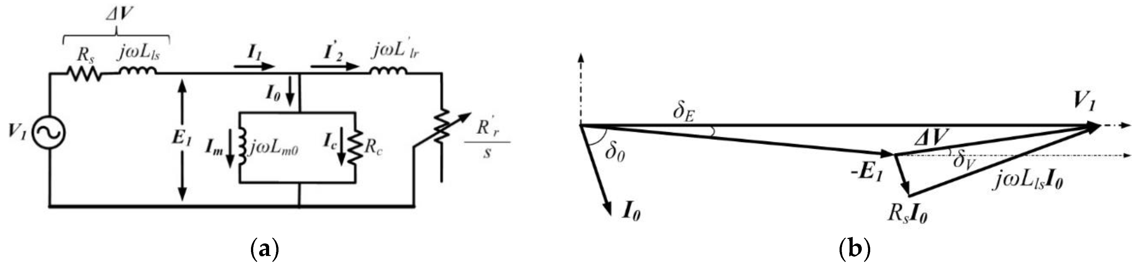
2.3. Three-Phase Squirrel Cage Induction Motor (SCIM) Analysis

The classical analysis of the three-phase SCIM is performed with the equivalent circuit (EC) per phase, as in Figure 1a [19]. In a rewinding process, when the winding is modified the voltage drop (ΔV) in the stator winding and no-load current (I0) vary because parameters Rs and Lls change.
Figure 1b shows the phasor diagram of the EC under no-load operation of the SCIM. In Equation (5) the relation between circuit equation and the EC as shown in Figure 1 is presented:
V 1 = E 1 cos ( δ E ) + 1 + ( R s ω L l s ) 2 ω L l s I 0 cos ( δ V ) ,
where δV is the angle between phasors ΔV (voltage drop) and V1 (supply voltage) and δE is the angle between phasors V1 e E1 (induced voltage). The phasor V1 is the reference (0°) and considering:
  • δE very small (E1cos(δE) ≈ E1);
  • the angle δV is a function of ωLls/Rs;
  • as well as the factor of voltage drop (KΔV = [1 + (Rs/ωLls)2]1/2);
The complete equation is given in (6):
V 1 E 1 + ω L l s I 0 K Δ V cos ( t g 1 ( ω L l s R s ) δ 0 ) ,
where δ0 is the angle between phasors V1 e I0.
The power factor at no-load is not larger than 0.3 and thus the angle δ0 is larger than 70° for low-power SCIM. In this paper, it is considered δ0 equal to 80° because the angle was measured [19]. Thus, from the motor’s parameters with former winding, the no-load current of a rewound SCIM is represented by (7):
I 0 V 1 E 1 ω L l s ξ ,
where I0 is the new value of no-load current and, Lls is the new value of stator leakage inductance. The factor ξ is presented in (8):
ξ = γ cos [ t g 1 ( ω L l s R s K f i l l K f i l l l s + C y + D l s + C y + D ) δ 0 ] cos [ t g 1 ( ω L l s R s ) δ 0 ] ,
where Rs, Kfill, y, C and D are the new values of stator resistance, slot fill factor, coil span, and constants which vary for each winding. Completing (8), the factor γ is presented in (9):
γ = K Δ V K Δ V = 1 + ( R s / ω L l s ) 2 ( K f i l l K f i l l l s + C y + D l s + C y + D ) 2 1 + ( R s / ω L l s ) 2 ,
where KΔV is the new factor of voltage drop and, in sequence, the new value of stator current (I1) is shown in (10):
I 1 = I 0 2 + I 2 2 ,
where the rotor current or load current (I2) does not vary in the rewound motor, i.e., it is constant and it can be calculated in the motor with former winding [19].

2.4. Efficiency Calculation

The efficiency calculation with equivalent circuit presented in Figure 1a is based on summation of known losses which can be predicted analytically. Stator losses of the new winding (Ps) are easily calculated by (11):
P s = 3 R s I 1 2 .
The iron losses (Pfe) are measured from no-load tests as well as the friction and windage losses (PFW) and they are no-load losses [19]. PFW are constant regardless of the new winding if the bearings and mechanical seals are maintained. If the bearings and mechanical seals are changed for new original ones then a new evaluation of the friction and windage losses should be carried out. The third option is if there are new technologies of bearings and seals. In this last option, models of prediction must be used to estimate friction and windage losses [20,21]. If the fan is changed, a new prediction in windage losses must also be performed [20].
Iron losses are evaluated from measurements in the motor with former winding. Considering induced voltage constant after rewinding the relation among iron losses, number of turns and fundamental winding factor is shown in (12):
P f e = P f e ( K W 1 W 1 K W 1 W 1 ) 2 ,
where Pfe, KW1 and W1 are the iron losses, winding factor and number of turns after rewinding. The rotor losses (Pr) vary directly with rotor speed. THD presents a relation between harmonics winding factors (K) and the fundamental one (KW1), as in (13) [22]:
T H D = ν = 3 , 5 , 7 , 9 , 11 , ( K W ν ν ) 2 K W 1 .
In (13) the reduction in (K) also reduces the harmonics which produces reverse torques to the movement, i.e., a reduction in THD decreases the slip (s), the slip speed (nsn), and increases the rotor speed (n). Thus, from rotor losses measured in motor with former winding is possible to predict the rotor losses in rewound motor from (14):
( n s n ) = ( n s n ) T H D T H D ,
where ns is the synchronous speed, n is the rotor speed after rewinding and THD is the total harmonic distortion of the new winding. In (15) is presented the relation between Pr and slip speed:
P r = ( n s n ) ( n s n ) P r ,
where Pr is the rotor losses after rewinding. The maintenance of the air gap input power after rewinding is the only condition to perform a strategic rewinding. Table 2 presents values of parameters calculated to the useful windings, including efficiency (η) given in (16) for a new winding:
η = P o u t P o u t + ( P s + P f e + P r + P F W ) ,
where Pout is the output power at the shaft.
The reference motor is a three-phase SCIM, type IE2, 1.5 HP, 60 Hz, 380 V, one pair of poles and Y-connection. The original winding is concentric, with 24 slots, four slots/pole/phase, 212 turns per phase and each turn has two parallel strands made of aluminum (Al) with a diameter equal to 0.63 mm (AWG) each strand (2 × Ø0.63 mm). Table 2 presents the results for y/τ = 0.917, y/τ = 0.833 and, y/τ = 1 using the following slot fill factors: Kfill = 30.6% (2 × Ø0.55 mm) e Kfill = 40.2% (2 × Ø0.63 mm) all with copper strands (Cu). The number of turns per phase is 216 for short pitch windings with double layer and all wires types are AWG.
As seen in Table 2, the larger efficiencies are the SCIM with 2 × Ø0.63 mm (Kfill = 40.2%), regardless of shortening. However, just the motor with y/τ = 0.833 is above 85%. For the same coil pitch just the motor with 2 × Ø0.55 mm (Kfill = 30.6%) has efficiency between 84% and 85%. Thus, the following windings were rewound in three motors with same mechanical and thermal design (reference motor) and in sequence, measure their efficiencies.
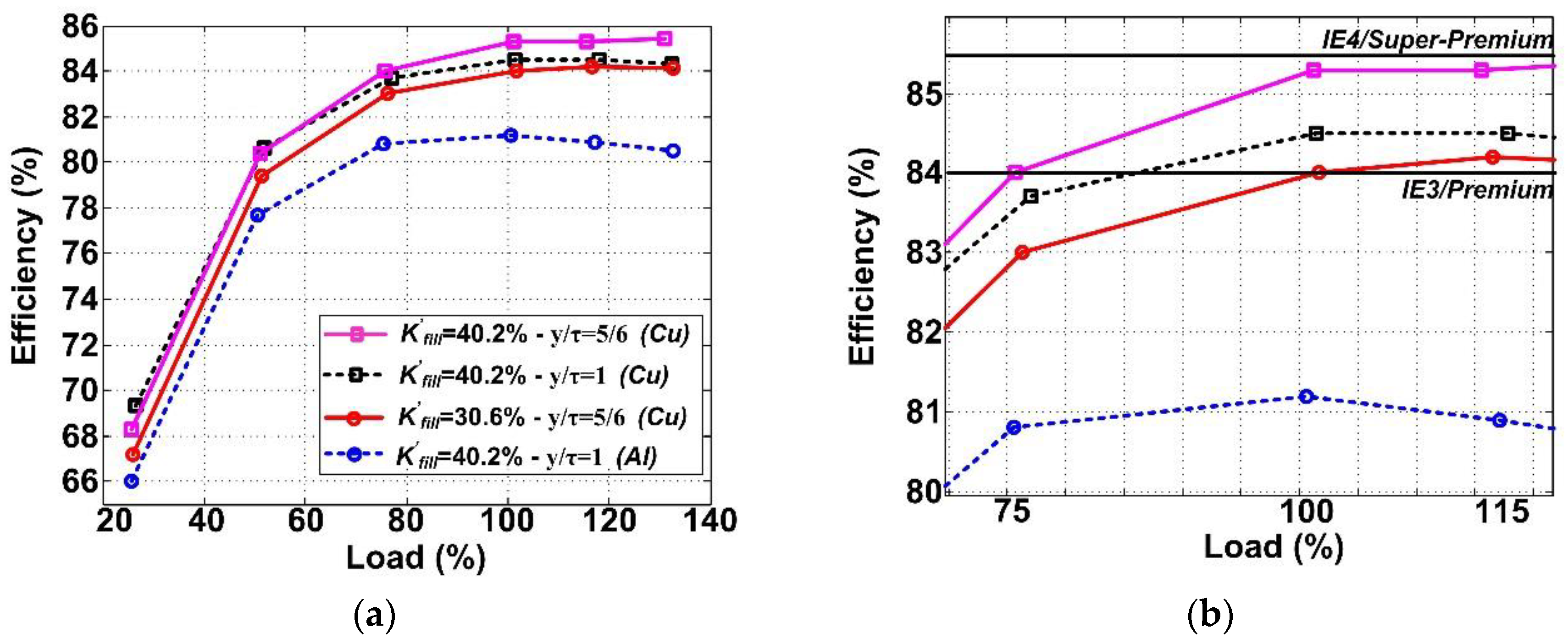
  • 2 × Ø0.63 mm (Kfill = 40.2%), with y/τ = 0.833, double layer and 216 turns per phase. Reason: this is the largest efficiency achieved and it is in the borderline of the IE4/Super-Premium class (this work considers IE4 threshold 85.5%, i.e., 1.5 percentage points above IE3 threshold and 12% less losses than IE3).
  • 2 × Ø0.55 mm (Kfill = 30.6%), with y/τ = 0.833, double layer and 216 turns per phase. Reason: the efficiency achieves IE3/Premium class with an intermediate slot filling (non-full), differently from the previous SCIM, but with the same coil pitch.
  • 2 × Ø0.63 mm (Kfill = 40.2%), with y/τ = 1, single layer e 212 turns per phase. Reason: likewise the previous SCIM, the efficiency achieves IE3/Premium class, but with full slot filling. The advantage is to achieve this class without changing the concentric winding for an imbricated winding. The only change is the strand material (Cu instead of Al).

3. Experimental Tests and Technical Considerations

All load tests are performed from a first step: an indirect measure of stator resistance and, in sequence, calculation of an average temperature in the winding for each load, as in method A and B of IEEE 112/2017 [19]. The load tests are made for 25%, 50%, 75%, 100%, 115% and 130% load. The following measurement and tests sequence was carried out:
  • Measuring stator resistance at ambient temperature [19]. In this paper, the ambient temperature is 25 °C.
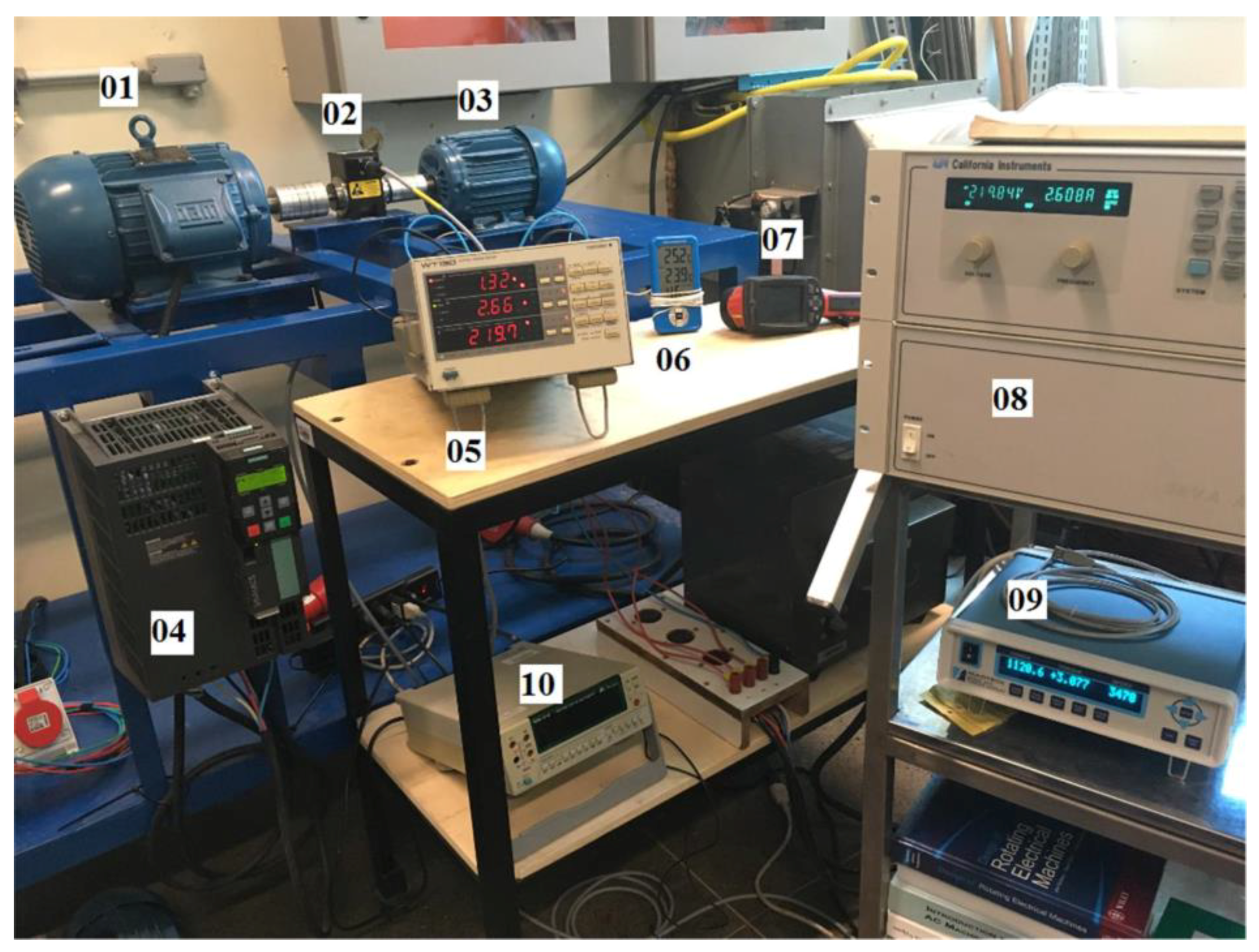
  • Carrying out no-load test as in [19]. For all tests are used a controlled power supply, model 3000 iL, 3 kVA, maximum current is 3.3 A/phase, manufactured by California Instruments® (San Diego, CA, USA).
  • Measuring stator resistance after thermal stability at no-load test, in a time below 30 s after turn-off the SCIM [19]. Before this, the temperature must be measured to confirm thermal stability. In this work, a model SD InfraCAM thermal imaging camera, by FLIR Systems® (Wilsonville, OR, USA) it was used. Figure 2 shows the measurement locus in the end winding.
  • Carrying out the load tests after the SCIMs achieve thermal stability. The stator resistance must be measured within 30 s after turning-off the motor, [19]. After this, the temperature of the end winding is measured, as previously presented. In sequence, the efficiency can be measured by method A [19]. This stage must be repeated for all previously listed loads (25%, 50%, 75%, 100%, 115% and 130%).
  • After the measurement of stator resistances under several load levels, the average temperature of the stator winding is calculated and the efficiency is measured again, but using method B for each load level, as in [19].
Efficiencies are thereby measured by two standardized methods and this will check the influence of methods A (direct measurement) and B (indirect measurement) on the economic analysis [23].

3.1. Workbench to Measure Efficiency by Methods A and B IEEE 112/2017

The workbench has a motor and an inverter which operates in four quadrants (4Q). The inverter is connected to a 5 HP, 380 V SCIM with one pair of poles, and the set works as a generator emulating load in the shaft of the SCIM under test, as illustrated in Figure 3 [24].
The motors are coupled in a torque transducer with a two-side shaft to measure torque, speed and power. The inverter is a model PM250 (7.5 kW/380 V) made by Siemens® (Munich, Germany), which connects the terminals of the 5 HP SCIM to the electrical grid. The torque transducer is manufactured by Magtrol® (Fribourg, Switzerland) and it has 10 N.m rated torque. The display, a model 3411, shows the measured data and the TORQUE 7® software (Fribourg, Switzerland) is available from the manufacturer for data acquisition via USB.

3.2. Efficiency Measurements and Determination of Efficiency Class

According Section 2, the windings with better efficiencies were assembled and the tests were performed to measure the efficiencies. Figure 4 shows the load profile results by method B [19].
It can be seen that the SCIM with higher Kfill, equal to 40.2%, and y/τ = 0.833 is close to IE4/Super-Premium threshold as previously expected. The SCIM with the same y/τ = 0.833 and intermediate Kfill = 30.6% achieves IE3/Premium however the SCIM with Kfill = 40.2% and concentric winding (y/τ = 1) achieves IE3/Premium with greater efficiency than previously. Table 3 presents measured values.
Table 4 presents the measured efficiencies at partial loads 50% and 75%, and above the full-load which is 115%, as shown in Figure 4b. Although the SCIM Kfill = 40.2% and y/τ = 0.833 is not absolutely within the IE4/Super-Premium class, it can be considered an IE4 class because the losses tolerance must be below 10% in the standards [1,2,3]. Therefore, the SCIM Kfill = 40.2% and y/τ = 0.833 is an IE4/Super-Premium because its losses tolerance is less than 3%. Finally, we can see that the applicability of MEPS in a low-power SCIM after rewinding is technically viable. The upper efficiency classes are achieved, including the non-regulated IE4/Super-Premium class. Important information is about NEMA/IEC performance indices as locked-rotor torque and locked-rotor current: the indices are within the limits if accordance tests are requested.

4. Economic Analysis

The economic analysis of a nationwide program to improve efficiency of electric motors is based on motor replacement and for this a cost-effectiveness test should be performed to measure the real impact of this action [12]. In 2017, for the first time, reconditioned motors are mentioned in a Brazilian regulation and this type of motors probably will be sold in Brazil [11]. In the regulation, the MEPS for reconditioned motors are equivalent to the IE3/Premium class [11]. Thus, the comparisons will be carried out between motor options which available on the Brazilian market (IE2 and IE3). The supposed replacement will be of an IE2 class motor by an IE3 and IE4/Super-Premium, and the motors after rewinding as seen in the previous section. For IE4/Super-Premium, the considered efficiency will be the same of threshold of the class and the considered price will be 15% above the IE3 price.

4.1. Life Cycle Cost Analysis (LCC)

The cost of a motor during its life cycle (CLCC) is very important for economic analysis and must be clear. The main costs are the initial investment, including the equipment’s acquisition, installation and commissioning, testing and also protection and control devices (I), the cost of electricity during its life cycle (E), the residual cost which appear with the disposal of the equipment after the end of its useful life (CRes), the cost of the replacement of a part of the equipment during its life cycle (CRepl) and the operation and maintenance costs (CO&M) [12]. The CLCC are presented in (17):
C L C C = I + E + C R e p l + C O & M C R e s ,
The electricity cost (E) is a function of load (L, p.u.), rated load (Pn, kW), annual operating hours (H, h/year), efficiency in function of load (η, p.u.), and the electricity tariff (T(t), US$/kWh), which varies with time t, as in (18) [25]:
E = P n L T ( t ) H η ( L ) .
The increase in electricity tariff with time is based on an average value from an historical series which show this trend [12,26]. This average value is the energy escalation rate (ê) and is an average value of a series which contain the difference between the electricity tariff and the inflation for each year (e(t)) [27,28]. Figure 5 presents the tariff value and inflation (normalized values), from 1996 to 2017, for the industrial sector in Brazil [12].
The energy escalation rate (ê) is presented in (19) and n is the number of years in the series from 1996 to 2017:
e ^ = t = 1 n e ( t ) n .

4.2. Cost-Effectiveness Test Methods

The cost-effectiveness of the investment of motors replacement considering the equipment’s life cycle is evaluated by the Net Present Value (NPV) [26]. The present value (PV) of a cash flow is given in function of the discount rate (d) and the energy escalation rate (ê) as presented in (20):
P V = t = 1 m C t ( 1 + e ^ 1 + d ) t ,
where Ct are the costs from the cash flow during equipment’s life cyle in m years [12].
The discount rates considered are typical for business firms, in the 10–12% range and the federal government rate based in the difference of its own official interest rate less inflation aiming to measure the program of energy efficiency in electric motors [12].

4.2.1. Net Savings Method (NS)

The Net Savings method (NS) is suitable to evaluate the cost-effectiveness of motor replacement because it compares the NPV along life cycle of the investment options [26]. This method is simple because it compares the continuity of the current situation (low efficiency) with the life cycle cost of the best situation (high efficiency) discarding similar costs, i.e., CO&M, CRes e CRepl [12]. Thus, the method is based on the balance of the increase of investments (for high efficiency option), ΔI, and the saved energy in the same option, ΔE. In (21) and (22) are presented ΔI and ΔE, in sequence:
Δ I = I h i g h e r I l o w e r ,
Δ E = E l o w e r E h i g h e r ,
where Ilower is the investment to maintain option with lower efficiency and Elower is the electricity consumption for option with lower efficiency. The Ihigher is the investment to second option, with higher efficiency and, Ehigher is the electricity consumption for this new option. Thus, the net savings (NS) in a life cycle of m years is presented in (23):
N S = t = 1 m Δ E ( 1 + e ^ 1 + d ) t t = 0 m Δ I ( 1 + d ) t ,
where m’ is the time whereupon the investment can be financed, however, in this case only one motor is purchased and all investment should be made in present time (t = 0) [12].
Therefore if NS > 0, there is economic viability in the motors replacement, else NS < 0, there is not economic viability but if NS = 0, there is a neutral result as known as economic viability threshold [12].

4.2.2. Saved Energy Cost (SE)

Another cost-effectiveness method which completes the analysis is the saved energy cost (SE). This method is given by the relation between the difference in investment in higher efficiency equipment and saved energy by the equipment, as in (24):
S E = Δ I Δ E .
The unity for SE is given in US$/MWh.

5. Methodology and Data

The methodology consists in the motors replacement analysis by some options with better efficiencies than aged SCIM type IE2. Among the options with higher efficiencies are presented:
  • IE3—Replacement of the existing SCIM IE2 by a new SCIM IE3/Premium of the same power.
  • IE4—Replacement of the existing SCIM IE2 by a hypothetical SCIM IE4/Super-Premium of the same power. The SCIM IE4 has efficiency equal to the class threshold (85.5%) and the price is 15% above the IE3 price.
  • Rew_IE3—Rewinding the existing SCIM IE2 in order to achieve the IE3/Premium class. The new winding has the following configuration: concentric winding with 2 × Ø0.63 mm, copper strands (Kfill = 40.2%), y/τ = 1, single layer, 212 turns per phase, 53 turns per slot and 53 turns per coil.
  • Rew_IE4—Rewinding the existing SCIM IE2 in order to achieve the IE4/Super-Premium class. The new winding has the following configuration: imbricated winding with 2 × Ø0.63 mm, copper strands (Kfill = 40.2%), y/τ = 0.833, double layer, 216 turns per phase, 54 turns per slot and 27 turns per coil.
  • Retrof_IE3—Replacement of the existing SCIM IE2 by a new SCIM IE2 that in the beginning of operation a rewinding was performed using this configuration: concentric winding with 2 × Ø0.63 mm, copper strands (Kfill = 40.2%), y/τ = 1, single layer, 212 turns per phase, 53 turns per slot and 53 turns per coil.
  • Retrof_IE4—Replacement of the existing SCIM IE2 by a new SCIM IE2 that in the beginning of operation a rewinding was performed using this configuration: imbricated winding with 2 × Ø0.63 mm, copper strands (Kfill = 40.2%), y/τ = 0.833, double layer, 216 turns per phase, 54 turns per slot and 27 turns per coil.
In the evaluations, the measured efficiencies by methods A and B in motors Retrof_1, Retrof_2, and IE2 class are used [19]. The considered efficiency of the existing SCIM IE2 will be reduced by 1.0 percentage point of the measured efficiency presented in Table 3 as well as Rew_IE3 and Rew_IE4 have the same decrease of 1.0 percentage point in measured efficiency according to Table 3 also [6]. However, for the SCIM IE3 only its nameplate efficiency (84.6% at full-load) has been used as well as two operational conditions will be evaluated: 4000 and 8000 operating hours per year. In sequence, the two following subsections are going to present motor prices and, after a market survey, an average cost for rewound motors are going to complete the data for economic analysis.

5.1. Motors Prices

The SCIM type IE1 is no longer sold on the Brazilian market or the US market. Therefore, the price for type IE1 will be the same price presented in [12], related to the year 2012. The prices of SCIM type IE2 and IE3/Premium, 1.5 HP, one pole pair, 380 V, are presented in Table 5 and they were obtained after a local market survey (conducted in Fortaleza City, State of Ceara) in 2017.
We can see that the price of a SCIM type IE3 unit is 44.6% larger than the price of an IE2. Regarding the hypothetical SCIM IE4, the price of an IE3 will be considered 15% above the SCIM IE3 price, i.e., US$456.14. The average increase in cost from the SCIM IE2 to IE3 is around 20% in Brazil, thus we expect a smaller average increase from IE3 to IE4, and we consider 15% [12]. The analysis will use extreme cases, i.e., SCIM IE4 with the lowest possible price and SCIM IE2 with probably better efficiency than a real motor in operation despite the reduction of efficiency [6]. Regarding reconditioning of a SCIM, in the same market survey some information was observed:
  • Reconditioning/Stator Winding Redesign includes swap of bearings, V-ring seals, fixing ring and wave washer, if necessary, in addition to the frame painting as demanded by the manufacturer. If a repair in a non-failed motor is requested, the same price is charged.
  • Generally, the rewinding workshop does not have expertise in recovery of a damaged squirrel cage rotor or damaged rotor shaft. However, in low-power motors, the squirrel cage rotor can be bought if the manufacturer provides it.
In any case, the average price of rewinding a low-power SCIM is obtained in the local market. Table 6 presents the rewinding cost of a motor group with different rated powers, pairs of poles and the relation between the cost of rewinding and the price of the SCIM.
It can be concluded that the average cost of a rewinding is around 25% of the purchase price for motors IE2 up to 5 HP. It can be noted that for a 10 HP SCIM this value is 20% of the purchase price. In this work, the considered cost for retrofitted motors, i.e., Retrof_IE3 and Retrof_IE4 are US$342.90 each (1.25 times US$274.32). The investment cost for cases Rew_IE3 and Rew_IE4 is US$68.58 (0.25 times US$274.32).

5.2. Input Data

In the proposed economic analysis the following parameters are based on the economics in Brazil on December 2017. The parameters presented here will be used in all subsequent analysis:
  • Discount rate (d) equal to 12% per year in the first analysis and 4% per year in the subsequent analysis which is composed of the national interest rate (6.9%) less inflation (2.95%) in December 2017. The second analysis presents how to measure the viability of an investment for a nationwide energy efficiency program.
  • The energy escalation rate (ê) is equal 3.01% per year. This rate was established in the increase of the average industrial electricity tariff from 1996 to 2017, less inflation (see Figure 5).
  • The industrial electricity tariff (C) is equal to 98.65 US$/MWh which is the average electricity tariff in Brazil (2017) [27]. In this tariff is discounted the possible variation of 18.05% [12]. This variation is due manifold tariffs of each electricity distribution companies in the country. As each electricity companies have its own tariffs, an average value is suitable. As the sensibility analysis performed in [12], the tariff is discounted by the variation because this action raises the viability threshold. The original tariff value was 120.38 US$/MWh.
  • Life cycle (m) considered for a 1.5 HP SCIM is 10 years [12,25].
  • The average cost of the IE2, IE3/Premium, IE4/Super-Premium, Retrof_IE3, Retrof_IE4, Rew_IE3 and Rew_IE4 units are presented in Section 5.1.
  • The technical motor data, e.g., efficiency and load, are presented in Section 2 and Section 3. The viability will be evaluated for 4000 and 8000 operation hours per year with 100% load. In sequence, only the two better cases will be evaluated at 75% load. If necessary, they will be evaluated at 50% load as well.
  • The currency exchange rate used is US$1.00 = R$3.13 and US$1.00 = R$3.24 (year 2017) for the values presented in Section 2.

6. Results and Discussion

In this section the technical and cost-effectiveness of an in-use motor’s replacement by a high efficiency motor during its life cycle time will be evaluated. Just the rewinding the motor will be evaluated as well as the rewound motors soon after purchasing them.

6.1. Cost-Effectiveness with Discount Rate 12%

In this section the results with a discount rate of 12% per year are shown. For this analysis, the motor operates at full-load, and the results for 4000 and 8000 h/year will be calculated considering the efficiencies measured by methods A and B. Table 7 presents the results from the larger net savings to the smallest.
For 8000 or 4000 operating h/year, regardless of efficiency measurement method, all options are economically viable. The better viability is with rewinding options without motor replacement (Rew_IE4 and Rew_IE3), as expected, but rewound motors soon after purchase shows better cost-effectiveness than motors IE3 and IE4 (Retrof_IE3 and Retrof_IE4). We can see that the reduction of operating h/year leads a better cost-effectiveness of IE3 than IE4 for the presented considerations.
It is important to highlight the payback of Rew_IE3 and Rew_IE4 is between 1 and 2 years for 8000 h/year and, for 4000 h/year the payback of Rew_IE3 is between 3 and 4 years and the payback of Rew_IE4 is 3 years. It can be concluded that SCIM Retrofit_IE3 and Retrofit_IE4 have the best results in life cycle economic analysis in relation to manufactured motors.
Another analysis is at 75% load but the SCIM IE4 class does not participate. Table 8 shows the net savings outcomes. We can see that the results at full load are the same at 75% load. The replacement of the SCIM IE2 by SCIM IE3 is at the viability limit at 75% load and 4000 operating h/year. Finally, we conclude that the motors after rewinding are the best option in relation to motor replacement from an existing SCIM IE2 by a SCIM IE3 or IE4. This conclusion is reached taking into account the number of operating hours and the motor load and, the results are independent of the efficiency measurement method used.

6.2. Cost Effectiveness with Discount Rate 4% in Brazil

In this section, the same analysis of Section 6.1 is going to be presented, but using a discount rate of 4% per year. The 4%discount rate represents the electricity cost in an energy efficiency nationwide program [12]. Table 9 presents similar outcomes as in Table 7.
Clearly, the discount rate does not influence in general conclusions about the better cost-effectiveness of Retrof_IE3 and Retrof_IE4 in relation to IE3 and IE4 classes, even in Method B/8000 h/year, where the IE4 has US$3.30 more in the net savings than Retrof_IE3. How this behavior does not hold in other situations, so we confirm the general conclusion.
We confirm that the IE3 class is more cost-effective than IE4 class at 4000 h/year at full-load as we see in Table 7 and Table 9. The reduction of operating h/year reduces the energy consumption between high-efficient investment options. Therefore, there is a minimum limit of the saved energy where its cost-effectiveness is better than an option with smallest efficiency. Below this limit the cost-effectiveness of the motor with higher efficiency (IE4) is smaller than the cost-effectiveness of the IE3 (efficiency smaller than IE4). We conclude that the varying of operating h/year can change the economic planning for an energy efficiency action in three-phase low-power motor due the non-linearity between ΔE and ΔI in net savings method.
An interesting point is related to the influence of the measured efficiencies on net savings in a situation of less discount rate, according to the “8000 operating h/year” columns in both Table 7 and Table 9. The increase in measured efficiency from method B to method A, in Retrofit_IE3, changes the net savings in the situation of less discount rate. The same analysis results with 75% load are presented in this section. Table 10 shows the net savings outcomes.
We can see that the results at full load are the same as at 75% load for both discount rates (Table 8 and Table 10). The replacement of the SCIM IE2 by SCIM IE3 is viable at 75% load and 4000 operating h/year, differently from the 12% discount rate. Then, the cost-effectiveness threshold is less than at 4% discount rate and shows a clearly dependence between discount rate and the cost-effectiveness. Finally, we confirm that the motors after rewinding are the best option compared to motor replacement of an existing SCIM IE2 by a SCIM IE3 or IE4, as mentioned in Section 6.1 above.

6.3. Saved Energy Cost

Considering the saved energy cost (SE), as in (23), Table 11 presents the results and ranking from the lowest energy savings to the highest. We can see the smallest saved energy costs are in the motors after retrofitting, Retrof_IE3 and Retrof_IE4. The economic viability of these motors is confirmed because these options save energy at low cost.

7. Conclusions

The technical and economic viability of low-power motor replacement, after the end of life cycle, by rewound motors has been presented. The paper compared the replacement of an existing IE2 class motor by two rewound motors options soon after purchasing them, by one IE3 and by another IE4 and other options without motor replacement, i.e., the rewinding of the existing motor. All rewound motors were equipped with efficient windings which increase their efficiency between 3 and 4 percentage points.
It was concluded that the rewinding of the existing IE2 motor replacing the former windings for efficient windings is the most cost-effective option for industry. A reconditioning process is necessary and it is included in the cost of the rewinding. In second place we find the replacement of an existing IE2 by rewound motors soon after purchasing them to have better cost-effectiveness than IE2 replacement by an IE3 class unit, available on Brazilian market, or a hypothetical IE4. This is regardless of the efficiency measurement method used, or the number of operating hours per year, but the cost-effectiveness is strongly dependent on the motor load. Low power motors in Brazil have to operate at high load. If this action is part of a nationwide energy efficiency program, the results shows high economic and technical viability to promote public energy efficiency policies for rewound electric motors, in the rewinding process and efficiency and economic viability measurements. In the industry, such investment ensures the payback is less than 2 years, even with discount rate of 12%.
The cost of the motor after rewinding was defined and the analysis was performed under extreme considerations, i.e., the lowest electricity tariff possible and IE4/Super-Premium with the lowest cost and the highest efficiency. Technically, rewound 1.5 HP, one pair of poles induction motors in Brazil are economically viable to loads between 100% and 75% or less, but the viability threshold depends on the discount rate. Therefore, the conclusions presented in this paper are suitable for a Brazilian electric motor market in the previously described current economic situation.

Author Contributions

V.P.B.A. and R.S.T.P. conceived and designed the experiments and together with F.J.T.E.F. analyze the data; V.P.B.A. performed the experiments and validate. All authors contributed equally for articulate the research work in its current form as full research manuscript.

Funding

This research was funded by CNPQ grant number 459091/2014-0.

Acknowledgments

The authors would like to thak to Eng. Salustiano for collaboration with this work and UFERSA.

Conflicts of Interest

The authors declare no conflict of interest.

References

  1. ABNT. Rotating Electrial Machines-Induction Motors, Part 1: Polyphase; NBR 17094-1; ABNT: Sao Paulo, Brazil, 2013. [Google Scholar]
  2. IEC. Rotating Electrical Machines: Efficiency Classes of Line Operated AC Motors (IE Code); IEC Std. 60034-Part 30-1; IEC: Geneva, Switzerland, 2014. [Google Scholar]
  3. ANSI NEMA Std. Motors and Generators-1-12; NEMA: Washington, DC, USA, 2016. [Google Scholar]
  4. De Almeida, A.T.; Ferreira, F.J.T.E.; Duarte, A.Q. Technical and Economical Considerations on Super High-Efficiency Three-Phase Motors. IEEE Trans. Ind. Appl. 2014, 50, 1274–1285. [Google Scholar] [CrossRef]
  5. Priority Energy Efficiency Project: Incentive to Replacement of Electric Motors: Promoting Energy Efficiency in the Motor Driven Systems Segment-ANEEL, 2015. Available online: www.aneel.gov.br/programa_eficiencia_energetica (accessed on 31 May 2018).
  6. Ferreira, F.J.T.E.; de Almeida, A.T. Induction motor downsizing as a low-cost strategy to save energy. J. Clean. Prod. 2012, 24, 117–131. [Google Scholar] [CrossRef]
  7. Aguiar, V.P.B.; Pontes, R.S.T.; Fernandes Neto, T.R.; Ferreira, F.J.T.E. Rewinding strategy aided by FEA as a solution to increase efficiency of industrial motors. In Proceedings of the 2016 XXII International Conference on Electrical Machines (ICEM), Lausanne, Switzerland, 4–7 September 2016; Capolino, G.A., Kawkabani, B., Eds.; IEEE: Piscataway, NJ, USA, 2016; pp. 2803–2809. [Google Scholar] [CrossRef]
  8. Ferreira, F.J.T.E.; Silva, A.M.; de Almeida, A.T. Software Tool for Fast and Optimized Design of Three-Phase Stator Windings of Induction Motors. In Proceedings of the 10th International Conference EEMODS’17 Energy-Efficient in Motor Driven Systems, Rome, Italy, 6–8 September 2017; Bertoldi, P., Ed.; Publications Office of the European Union: Luxembourg, 2018; pp. 370–389. [Google Scholar] [CrossRef]
  9. Cao, W.; Bradley, K.J. Assessing the impacts of rewind and repeated rewinds on induction motors: Is an opportunity for Re-designing the machine being wasted? IEEE Trans. Ind. Appl. 2006, 42, 958–964. [Google Scholar]
  10. ANSI/EASA Std. AR100. EASA Recommended Practice for the Repair of Rotating Electrical Apparatus; EASA: St. Louis, MO, USA, 2015.
  11. Brazil Ministry of Mines and Energy. Inter-Ministerial Ordinance no. 1, of June 29th, 2017-Aim Program for Squirrel Cage Three-Phase Induction Motors. Available online: www.mme.gov.br/web/guest/acesso-a-informacaoqlegislacao/portarias-interministeriais (accessed on 31 May 2018).
  12. Andrade, C.T.C.; Pontes, R.S.T. Economic Analysis of Brazilian Policies for Energy Efficient Electric Motors. Energy Policy 2017, 106, 315–325. [Google Scholar] [CrossRef]
  13. Boglietti, A.; Cavagnino, A.; Lazzari, M. Computational Algorithms for Induction Motor Equivalent Circuit Parameter Determination-Part I: Resistances and Leakage Reactances. IEEE Trans. Ind. Electron. 2011, 58, 3734–3740. [Google Scholar] [CrossRef]
  14. Boldea, I.; Nasar, S.A. Leakage Inductance and Resistances. In The Induction Machines Design Handbook, 2nd ed.; Grisby, L.L., Ed.; CRC Press: Boca Raton, FL, USA, 2010; pp. 119–142. [Google Scholar]
  15. Pyrhönen, J.; Jokinen, T.; Hrabovcová, V. Flux Leakage. In Design of Rotating Electrical Machines, 1st ed.; J. Wiley & Sons: Chichester, UK, 2008; pp. 225–254. [Google Scholar]
  16. Di Tommaso, A.O.; Genduso, F.; Miceli, R.; Galluzo, G.R. An Exact Method for the Determination of Differential Leakage Factors in Electrical Machines with Non-Symmetrical Windings. IEEE Trans. Magn. 2016, 52, 8107609. [Google Scholar] [CrossRef]
  17. Raziee, S.M.; Misir, O.; Ponick, B. Winding function Approach for Winding Analysis. IEEE Trans. Magn. 2017, 53, 8203809. [Google Scholar] [CrossRef]
  18. Misir, O.; Raziee, S.M.; Hammouche, N.; Klaus, C.; Kluge, R.; Ponick, B. Prediction of Losses and Efficiency for Three-Phase Induction Machines Equipped with Combined Star-Delta Windings. IEEE Trans. Ind. Appl. 2017, 53, 3779–3787. [Google Scholar] [CrossRef]
  19. IEEE Standard 112-2017 Test Procedure for Polyphase Induction Motors and Generators (Revision of IEEE Std. 112-2004). Available online: Ieeexplore.ieee.org/document/8291810 (accessed on 24 May 2018).
  20. Tong, W. Motor Power Losses. In Mechanical Design of Electric Motors, 1st ed.; CRC Press: Boca Raton, FL, USA, 2014; pp. 369–408. [Google Scholar]
  21. Concli, F.; Della Torre, A.; Gorla, C.; Montenegro, G. A New Integrated Approach for the Prediction of the Load Independent Power Losses of Gears: Development of a Mesh-Handling Algorithm to Reduce the CFD Simulation Time. Adv. Tribol. 2016, 2016, 2957151. [Google Scholar] [CrossRef]
  22. Lipo, T.A. The MMF and Field Distribution of an AC Winding. In Introduction to AC Machine Design, 3rd ed.; University of Wisconsin-Madison: Madison, WI, USA, 2007; pp. 59–94. [Google Scholar]
  23. Agamloh, E.B. Induction Motor Efficiency—A comparison of direct and indirect measurements. IEEE Ind. Appl. Mag. 2011, 17, 20–28. [Google Scholar] [CrossRef]
  24. Quintino, A.; Abrantes, N.; Ferreira, F.J.T.E.; de Almeida, A.T. Four-Quadrant Electric Motor Test Bench with a Fully Programmable Load Profile. In Proceedings of the 7th International Conference EEMODS’11 Energy-Efficient in Motor Driven Systems, Alexandria, VA, USA, 12–14 September 2011; Bertoldi, P., Trenev, G., Eds.; Publications Office of the European Union: Luxembourg, 2013; pp. 176–185. [Google Scholar] [CrossRef]
  25. De Almeida, A.T.; Ferreira, F.J.; Fong, J.; Fonseca, P. EUP Lot 11 Motors; Final Report; ISR-University of Coimbra: Coimbra, Portugal, 2008. [Google Scholar]
  26. Fueller, S.K.; Petersen, S.R. Life-Cycle Costing Manual for the Federal Energy Management Program, 2nd ed.; US Department of Commerce-NIST: Washington, DC, USA, 1996. Available online: https://www.nist.gov/publications/life-cycle-costing-manual-federal-energy-management-program-nist-handbook-135-1995 (accessed on 31 May 2018).
  27. Reports of the Revenue and Consumption in Electricity Distribution-ANEEL. Available online: www.aneel.gov.br/relatorios-de-consumo-e-receita (accessed on 31 May 2018).
  28. IPEA Ipeadata. Available online: www.ipeadata.gov.br (accessed on 31 May 2018).
Figure 1. Squirrel cage induction motor (SCIM) analysis: (a) Equivalent circuit per phase; (b) Phasor diagram at no-load operating.
Energies 11 01701 g001
Figure 2. Temperature measured in the stator end-winding at full-load: (a) locus and; (b) measuring by thermal imaging camera.
Energies 11 01701 g002
Figure 3. Workbench for efficiency measurement test A and B. (01) Load SCIM; (02) Torque transducer; (03) SCIM under test; (04) Four quadrants (4Q) inverter; (05) Digital wattmeter; (06) Thermohygrometer; (07) Thermal imaging camera; (08) Controlled power supply source; (09) Torque transducer display; (10) Digital ohmmeter.
Energies 11 01701 g003
Figure 4. Load profiles with measured efficiencies and comparison with minimum efficiency performance standard (MEPS) (84.0% for IE3 and 85.5% for IE4): (a) Full motor’s efficiency profile with load from 25% to 130%; (b) Details in measured efficiency between load 75% and load 115%.
Energies 11 01701 g004
Figure 5. Evolution of the average industrial tariff of electricity and the inflation rate in Brazil from 1996 to 2017 [27,28].
Energies 11 01701 g005
Table 1. Winding analysis of different symmetrical windings.
y/τ10.9170.8330.75
TypeConc. 1/S.L. 2Imbric. 3/D.L. 4Imbric./D.L.Imbric./D.L.
σ0 (%)0.890.740.620.69
KW1 (%)95.894.992.588.5
KW5 (%)20.516.35.37.9
KW7 (%)15.89.64.114.6
KW11 (%)12.61.612.24.8
KW13 (%)12.61.612.24.8
KW17 (%)15.89.64.114.6
KW19 (%)20.516.35.37.9
THD* (%)9.08.17.47.8
1 Concentric winding; 2 Single layer; 3 Imbricated winding; 4 Double layer.
Table 2. Analytically calculated motor-key parameters before rewinding.
2 × ØPitchRs (Ω)Rs/ωLlsωLls (Ω)KΔVI0 (A)I1 (A)η (%)
0.63 mm (Al)Full5.70.9406.11.3721.252.4281.9
0.55 mm (Cu)Full4.40.7336.01.2401.302.4483.7
0.9174.20.8385.01.3051.532.5783.8
0.8333.90.8594.51.3181.682.6784.3
0.63 mm (Cu)Full3.30.5506.01.1411.342.4684.9
0.9173.20.6395.01.1871.582.6084.9
0.8333.00.6614.51.1991.742.7085.4
Table 3. Comparison between calculated and measured values: full-load efficiencies, stator currents and no-load currents.
2 × ØPitchη (%)η (%) Method Bη (%) Method AI1 (A)Meas. * I1 (A)I0 (A)Meas. I0 (A)
0.63 mm (Al)Full81.981.281.82.422.421.251.25
0.55 mm (Cu)0.83384.384.084.32.672.581.681.59
0.63 mm (Cu)Full84.984.585.12.462.461.341.33
0.83385.485.385.72.702.621.741.66
* Measurements.
Table 4. Measured efficiencies for 50%, 75% and 115% loads.
2 × Ø
Pitch
η (%) 50%
Method B
η (%) 50%
Method A
η (%) 75%
Method B
η (%) 75%
Method A
η (%) 115%
Method B
η (%) 115%
Method A
0.63 mm (Al) Full77.778.380.881.680.981.2
0.55 mm (Cu) 0.83379.479.683.083.584.284.0
0.63 mm (Cu) Full80.682.483.784.084.584.9
0.63 mm (Cu) 0.83380.480.984.084.785.385.7
Table 5. Prices of SCIM 1.5 HP, 1 poles pair, 380 V, types IE1, IE2 and IE3/Premium.
SCIM TypeIE1IE2IE3/Pemium
Price (US$)105.14274.32396.64
Table 6. Average Market Prices and Rewinding Cost of SCIM IE2 class from 1.5 HP to 10 HP.
Power (HP)Pair of PolesMotor Price (US$)SCIM Rewinding Cost (US$)Relation (%)
1.51274.3260.7322.1
1.52309.1171.2823.1
21338.4485.3425.2
31412.3998.1323.8
51572.43144.8025.3
52586.97144.8024.7
1021025.30195.3019.0
Table 7. Economic Viability and Net Savings for Motor Options at Full (100%) Load with Discount Rate 12% per year.
100% Load
8000 Operating h/year4000 Operating h/year
Method BNS 1 (US$)Method BNS (US$)
(1) Rew_IE4555.10(1) Rew_IE4380.40
(2) Rew_IE3489.60(2) Rew_IE3347.70
(3) Retrof_IE4360.90(3) Retrof_IE4146.10
(4) Retrof_IE3296.90(4) Retrof_IE3114.20
(5) IE4263.40(5) IE364.50
(6) IE3251.20(6) IE440.80
Method ANS (US$)Method ANS (US$)
(1) Rew_IE4534.00(1) Rew_IE4369.90
(2) Rew_IE3485.50(2) Rew_IE3345.60
(3) Retrof_IE4339.00(3) Retrof_IE4135.20
(4) Retrof_IE3291.70(4) Retrof_IE3111.50
(5) IE4210.10(5) IE337.80
(6) IE3197.90(6) IE414.10
1 Net savings.
Table 8. Economic Viability and Net Savings for Motor Options at Load 75% and Discount Rate 12% per year.
75% Load
8000 Operating h/year4000 Operating h/year
Method BNS (US$)Method BNS (US$)
(1) Rew_IE4414.50(1) Rew_IE4310.10
(2) Rew_IE3395.60(2) Rew_IE3300.70
(3) Retrof_IE4202.10(3) Retrof_IE466.80
(4) Retrof_IE3183.70(4) Retrof_IE357.60
(5) IE3136.10(5) IE36.90
Method ANS (US$)Method ANS (US$)
(1) Rew_IE4404.30(1) Rew_IE4305.00
(2) Rew_IE3360.70(2) Rew_IE3283.20
(3) Retrof_IE4190.90(3) Retrof_IE461.20
(4) Retrof_IE3148.40(4) Retrof_IE339.90
(5) IE382.40(5) IE3−20.00
Table 9. Economic Viability and Net Savings for Motor Options at Full (100%) Load with Discount Rate 4% per year.
100% Load
8000 Operating h/year4000 Operating h/year
Method BNS (US$)Method BNS (US$)
(1) Rew_IE4716.40(1) Rew_IE4461.10
(2) Rew_IE3620.70(2) Rew_IE3413.20
(3) Retrof_IE4559.20(3) Retrof_IE4245.30
(4) IE4469.10(4) Retrof_IE3198.60
(5) Retrof_IE3465.80(5) IE3150.70
(6) IE3423.80(6) IE4143.60
Method ANS (US$)Method ANS (US$)
(1) Rew_IE4685.70(1) Rew_IE4445.70
(2) Rew_IE3614.70(2) Rew_IE3410.20
(3) Retrof_IE4527.40(3) Retrof_IE4229.40
(4) Retrof_IE3458.10(4) Retrof_IE3194.70
(5) IE4391.10(5) IE3111.80
(6) IE3345.80(6) IE4104.70
Table 10. Economic Viability and Net Savings for Motor Options at Load 75% and Discount Rate 4% per year.
75% Load
8000 Operation h/year4000 Operation h/year
Method BNS (US$)Method BNS (US$)
(1) Rew_IE4510.90(1) Rew_IE4358.30
(2) Rew_IE3483.30(2) Rew_IE3344.50
(3) Retrof_IE4327.20(3) Retrof_IE4129.30
(4) Retrof_IE3300.20(4) Retrof_IE3115.80
(5) IE3255.50(5) IE366.60
Method ANS (US$)Method ANS (US$)
(1) Rew_IE4496.00(1) Rew_IE4350.90
(2) Rew_IE3432.30(2) Rew_IE3319.00
(3) Retrof_IE4310.80(3) Retrof_IE4121.10
(4) Retrof_IE3248.60(4) Retrof_IE390.00
(5) IE3176.90(5) IE327.3
Table 11. Saved Energy Cost for All SCIM’s options in Full-Load (100%).
8000 Operation h/year
Method BSE(US$/MWh)
(1) Retrofit_IE41.04
(2) Retrofit_IE31.22
(3) IE32.14
(5) IE42.66
Method ASE(US$/MWh)
(1) Retrofit_IE41.10
(2) Retrofit_IE31.24
(3) IE32.50
(5) IE43.03

