Article

Fly Ash Formation and Characteristics from (co-)Combustion of an Herbaceous Biomass and a Greek Lignite (Low-Rank Coal) in a Pulverized Fuel Pilot-Scale Test Facility

by
Aaron Fuller
1,*,
Jörg Maier
1,
Emmanouil Karampinis
2,3,
Jana Kalivodova
4,5,
Panagiotis Grammelis
2,3,
Emmanuel Kakaras
2,3 and
Günter Scheffknecht
1
1
Institute of Combustion and Power Plant Technology, University of Stuttgart, Pfaffenwaldring 23, 70569 Stuttgart, Germany
2
Centre for Research & Technology Hellas/Chemical Process and Energy Resources Institute (CERTH/CPERI), Egialias 52, 15125 Marousi, Athens, Greece
3
National Technical University of Athens/Department of Mechanical Engineering/Laboratory of Steam Boilers and Thermal Plants (NTUA/LSBTP), Heroon Polytechniou 9, 15780 Zografou, Athens, Greece
4
The Energy Research Center of The Netherlands (ECN), Biomass, Coal and Environmental Research, Heat and Power Generation, P.O. Box 1, 1755 ZG Petten, The Netherlands
5
Research Centre Rez, Husinec-_Re_z _c.p. 130, 250 68 Husinec e_Re_z, Czech Republic
*
Author to whom correspondence should be addressed.
Energies 2018, 11(6), 1581; https://doi.org/10.3390/en11061581
Submission received: 1 May 2018 / Revised: 23 May 2018 / Accepted: 5 June 2018 / Published: 15 June 2018

Abstract

:
The lignite boilers are designed for lower quality fuels, and often the ash is not utilized. This work assessed the impact of combustion of an herbaceous biomass with a low-quality Greek lignite on the quality of the resulting fly ash. Test results were compared with those of fly ash samples from an industrial facility using the same fuel qualities. Inductively coupled plasma-optical (ICP) emission spectroscopy, X-ray powder diffraction (XRD), and scanning electron microscope (SEM) analyses were performed on the collected samples. Despite the significantly higher contents of K, Na and S in the biomass, at a 50% co-firing thermal share, the major and minor oxides in the fly ash were comparable to the lignite fly ash quality. This is attributed to the high ash content of the lignite, the low ash content of the biomass, and the much higher heating value of the biomass. There were improvements in fly ash performance characteristics with the herbaceous biomass in the fuel blend. The initial setting time and volume stability evaluations were improved with the biomass in the fuel blend. The work supports efforts of good practices in ash management, social responsibility, a circular economy, power plant renewable energy operations, and co-firing herbaceous biomass fuels in lignite power plants.

1. Introduction

Over the last decades there has been increased interest in developing bioenergy technologies worldwide due to declining energy supplies and severe environmental constraints associated with fossil fuel use [1]. The goal of the European Union is to increase the percentage of biomass fuels used in the primary energy consumption, offering a reasonable, acceptable option to reduce greenhouse emissions [1], mainly CO2. However, there are still concerns regarding the acceptability of coal and biomass fuel blends’ ash materials, i.e., by-product quality, current utilization, and disposal routes.
It is not possible to correctly predict properties of ash material generated from combustion of a fuel mixture from known characteristics of ash produced from each fuel [1]. The interactions between fuels are poorly understood, and unanticipated ash properties may arise when combusting fuel mixtures [1], so, it is important to fully characterize the ashes produced from burning and co-firing any relatively new biomass fuel.
The reaction mechanisms of ash formation involve melting of most of the mineral components in the fuel, the formation of small fused drops, and a subsequent sudden cooling that transforms the merged drops partly or entirely into spherical glass particles [2]. Smaller fly ash particles may cool down more rapidly during the cooling process resulting in a more glassy state and giving rise to a higher reactivity [3]. The fly ash yield is the inorganic residue resulting from the complete combustion (or oxidation) of fuel (e.g., coal or biomass), and it consists of original and new inorganic mineral phases formed from the inorganic, organic, and fluid components in the fuel [4]. An overview of the physical transformation involved in the formation of ash during coal combustion is depicted in Figure 1.
Lignite fly ash is subject to comparatively larger fluctuations compared to coal ashes [6]. Moreover, lignite boilers are designed for lower quality fuels, and often the ash is not utilized, making co-firing in lignite boilers an attractive solution to improving the ash quality [7]. Co-firing ash generated with ratios within the interest of commercial operation at power plants has proven to be applicable in concrete [8]. Those co-firing experiences mostly employed bituminous coals. Co-firing experiments with herbaceous or agricultural biomass in pulverized fuel power plants or test facilities focusing on fly ash quality are limited [9].
Lignite fly ashes have been used for refilling open cast mines, underground mining, surface restoration, soil amendment (mechanical stabilization and stabilization or strengthening of a soil), immobilization purposes, hydraulic road binders, plaster and mortar, road construction, asphalt filler, blended cement (contributing to CO2 reduction during the production process), concrete addition (only after receiving technical approval), and various environmental uses (retention of pollutants and soil rehabilitation) [6]. Lignite fly ashes have been successfully tested or used in self-consolidating concrete [10], an adsorbent for SO2 removal (after separation of enriched carbon fractions) [11], and in combination with a biochar or other organic amendments for improving soil properties [12]. Biochar and fly ash has the potential to improve soil quality, crop yield, and expand the carbon pool for soils [12]. Lignite coal fly ash blended with waste glass was successfully tested in the manufacture of lightweight aggregates [13]. Lignite fly ash with a high calcium content and used in a fly ash reinforced aluminum based metal matrix composite developed a good hardness due to the increased complex Si- and Ca-Si-crystalline phases produced [14]. A high Ca fly ash (CaO > 30%) has been used as a starting material when a hydrothermal calcination process is used as the pathway of the belite synthesis [15]. Thus, there are various options to use lignite fly ashes beyond the most stringent material provision requirements, i.e., beyond concrete addition. Special topics needed to be addressed by producers and users of combustion residues include, among others, co-combustion of coal with biomass that lead to changes in fly ash quality and its value as a marketable product [16].
There is a need for the development of new applications for lignite coal fly ash in order to reduce reliance on landfills [13]. More limited is the literature on the use of herbaceous biomass for co-firing with lignite. Thus, more work is needed that report the potential impact on ash quality that affects its sale or disposal routes due to a compositional changes from herbaceous or agricultural biomass co-fired with lignite.
Many of the problems associated with mono-combustion of biomass fuels may be ameliorated by co-combustion with coal, but the effect on the ash quality may be considered a downside of co-firing [16]. A major challenge for researchers, produces, users, and regulators is to improve the utilization of all grades of fly ash [16]. In this work the ash quality from co-firing an herbaceous biomass with a low-quality Greek lignite was evaluated. The species Cynara cardunculus shows significant potential as an energy crop under the semiarid conditions of the southern EU countries [17]. There is a need to provide solutions to the fly ash management problem from lignite coal power plants in many countries, e.g., Greece [13]. Fly ash should undergo a broad and critical assessment before being disposed, with an aim to provide one option for beneficial use in construction materials, which reduces disposal costs that account for short-term and long-term challenges [18]. The work reported in this paper elucidates the chemical, mineralogical, mobility, and some mechanical properties of the fly ash samples, as motivation for their potential utilization. The co-firing results are compared to the combustion of the unblended fuels to identify interactions between the lignite and biomass that affect the fly ash characteristics from the fuel blend. The data obtained provide valuable information on the ash quality in the area of co-combustion of agricultural or herbaceous biomass for heat and power production in a pulverized fuel facility and the by-product quality. The quality of an ash has meaning when viewed in the context of a certain application, as varying qualities are suitable for different applications [16]. Therefore, co-firing of a low-quality lignite with a herbaceous biomass may led to results warranting regulations requiring a certain co-firing ratio in older lignite power plants, if handling, transporting, storage, milling, feeding, boiler operations, and flue gas cleaning devices are not negatively impacted.

2. Materials and Methods

2.1. Facility

Figure 2 shows a diagram of the pilot-scale test facility. The facility consists of a cylindrical combustion chamber with a top-fired swirl burner, a selective catalytic reduction (SCR) catalyst, an electrostatic precipitator (ESP), and a fabric filter. In the inner annulus of a swirl burner, the coal is injected with primary air, and a center pipe allows injecting of secondary fuels. The computer aided monitoring system for the mass flow of the secondary fuel dosing system allows for a precise tuning of the desired biomass mass fraction in the fuel feed. The maximum thermal load of the facility is 0.5 MWth. A more detailed description is provided in [19].

2.2. Materials

The biomass type Cynara cardunculus L. (Cynara), which is characteristic of the Mediterranean countries, such as an agricultural or fast growing energy crop, and a low-quality Greek lignite were selected for this study. Also, blends of the lignite/biomass fuels were used in biomass percentages of 10% (typical of co-firing applications worldwide) and 50% on a thermal basis. A 1 mm sieve was used for grinding the Cynara pellets, as this is the size where larger particles are problematic for industrial pulverized fuel boilers. Preparation of the lignite occurred by using the fan beater mill that is part of the pulverized fuel pilot-scale test facility at the Institute of Combustion and Power Plant Technology (IFK). Because of the low heating value and high moisture content of the lignite, natural gas was used to support the flame in the near-burner region. The D10, D50, and D90 values of the Cynara were 33.72 μm, 244.01 μm and 838.34 μm, respectively. The lignite had a D50 of about 105 μm and D90 of about 475 μm. The larger particle size for Cynara is indicative of the need for a longer residence time to achieve a good burnout, which could influence fly ash formation, particle morphology, and mineral phases in the fly ash. The larger size will also impact the amount of ash at the various collection points, potentially affecting ash handling needs.
The lignite (low-rank coal) came from the open-cast mine near the Kardi Power Plant located in the Region of West Macedonia, near the cities of Ptolemaida and Kozani in Greece. The low quality of the lignite necessitated the use of natural gas, as shown in Table 1 of the following section.
The characterization of biomass fuels were performed according to the European standards drawn up by the Technical Committee CEN/TC 335 for solid biomass fuels. The determination of the proximate analysis was according to EN 51718, EN 51719 and EN 51720 for water, ash, and volatiles, respectively. Biomass ashes were produced using the standard at 550 °C. Determination of the ultimate analysis was according to EN 51732.
Ordinary Portland Cement of the class CEM I 42.5 R was used to prepare the concrete samples for strength testing. The sand (fine aggregate) used in making the test specimens was CEN-Norms and according to EN 196-1 conforming to ISO 679. The sand was stored at room temperature before use and in dry conditions. The fly ash was added as a partial replacement of cement at three levels: 10%, 20% and 30% by mass fraction.

2.3. Tests Operations

The direct co-combustion method was used during experimental testing [20,21]. The bio-fuel was handled and milled in a separate biomass milling facility, and it was injected into the pulverized fuel pipework before the burner inlet entrance. The feeding option utilized allows high co-firing ratios. Gas was used during the experiments due to the high water and ash contents (shown later) of the raw lignite, as it is widely known that those two fuel parameters adversely impact ignition and combustion stability. The use of gas ensured approximately a 300 kWel power output. Table 1 below lists the different test settings.

2.4. Ash Analyses

During the experiments, fly ash samples were collected from each ESP hopper. A representative fly ash sample of each test scenario was obtained from ash balance calculations of the hoppers. The fly ash was stored in a dry condition before testing.

2.4.1. Chemical Analyses

For fly ash analyses, major and minor elemental composition (expressed as oxides) were analyzed by inductively coupled plasma-optical emission spectroscopy (ICP-OES) to determine concentrations of the major and minor elements by EN 15290. Loss on ignition was identified for fly ash at 950 °C according to EN 196-2. Determination of trace elements for fly ash was according to EN 15297 or EN 22022-1-6. Determination of chlorine for fly ash was according to DIN 38414 and EN ISO 10304. The determination of leachable heavy metals and leachable S, K, Na, P and Cl was according to EN 15290, EN 15296 and DIN 38414 part 4. Biomass fuel ash oxide analysis was taken at 550 °C in accordance CEN/TC 335.

2.4.2. Scanning Electron Microscope (SEM)

Samples for SEM are generally prepared by dispersing the sample onto a conductive carbon tape (sample plate). Because of the insulating effect of the embedding material, samples are coated with gold to prevent charging. Afterwards, samples are placed in the SEM chamber. Images are taken with a phosphorus scintillation detector (secondary electron images) and a quadrupole backscatter detector. The addition of an X-ray spectrometer (normally of energy-dispersive type) makes it capable of chemical analyses, and spot analyses can be obtained [22]. Each fly ash sample was characterized by randomly selecting 3–4 fields of view and examining the morphology of each field. The elemental composition and morphology were worked out further for all fields for the different ESP ash hoppers for each test scenario.

2.4.3. X-ray Powder Diffraction Analyses (XRD)

Fly ash samples for XRD analyses were first finely ground. Fine grinding of the powder ensures there are sufficient amount of crystals to generate detectable signals at all angles and that the back-ground noise is kept to a minimum as possible [23]. A D8 Advance powder diffractometer (Bruker Advanced X-ray Solutions GmbH, Karlsruhe, Germany, with headquarters in Billerica, MA, USA) equipped with a Bragg-Brentano geometry and scintillation detector and CuKα radiation wavelength 1.5418 Å was used to determine mineral phases. The tube voltage was 40 kV, and the tube current was 40 mA. X-ray powder diffraction scans were performed at a diffraction angle range from 11° 2θ to 65° 2θ and with a step size of 0.02° 2θ and 1 s counting time per step. The evaluation of the X-ray results was done using the software DIFFRACPlus EVA Version 5.0 Revision 1, produced by Bruker Advanced X-ray Solutions GmbH (Karlsruhe, Germany).

2.4.4. Particle Size Distribution Determination

The particle sizes for the fly ash samples were measured in Malvern laser particle analyzers, model number 2000 and 2600 (Malvern, Malvern Hills, UK). A powdery sample is transported pneumatically by the light beam of a laser. The measuring range of the Malvern is from 25 to 500 μm.

2.4.5. Ash Enrichment Factors

An enrichment factor determines the relative enrichment of an element in the fly ash when compared to the amount of the element in the fuel ash. The enrichment factor is defined below (Equation (1)) as reported in [24]:
E F i = x d , i x a , i
where, EFi is the enrichment factor, xd,i is the mass fraction of element i in the fly ash on a carbon-free basis and xa,i is the mass fraction of element in the fuel ash or fuel ash blend.

2.4.6. Volume Stability Testing (Soundness)

Some constituents in fly ash, e.g., free lime (if no aeration converts it to carbonate or calcium hydroxide), sulfate, and periclase, can participate in reactions that lead to undesirable volume changes (unsoundness) in hardened concrete, causing deterioration and failure [25]. Volume stability testing was performed at the Material Testing Institute (MPA Stuttgart, Otto-Graf-Institute (FMPA), at the University of Stuttgart, Stuttgart, Germany). The soundness testing was conducted according to EN450-1 requirements that stipulate to follow procedures in EN 196-3. The test was done using the LeChatelier test method principal.

2.4.7. Initial Setting Time Testing

Setting is the process where a fresh cement paste of freely flowing or plastic consistency is converted into a set material, which has lost its unlimited deformability and crumbles under a sufficiently great external force [26]. Admixtures, to include fly ash, influence the setting times by either accelerating or retarding it [26]. The initial time of set was determined at the Material Testing Institute (MPA Stuttgart, Otto-Graf-Institute (FMPA)). The setting time is one of the most important properties of concrete [27]. The initial time of set test was conducted according to EN 450-1 requirements that stipulate to follow procedures in EN 196-3 for preparing the cement paste and adhering to requirements in EN 197-1. The results are from the penetration of a standard needle into a cement paste or cement and other admixture mortar, such as fly ash. The test involves measuring a penetration resistance of the needle after a period of time.

2.4.8. Compressive Strength Development

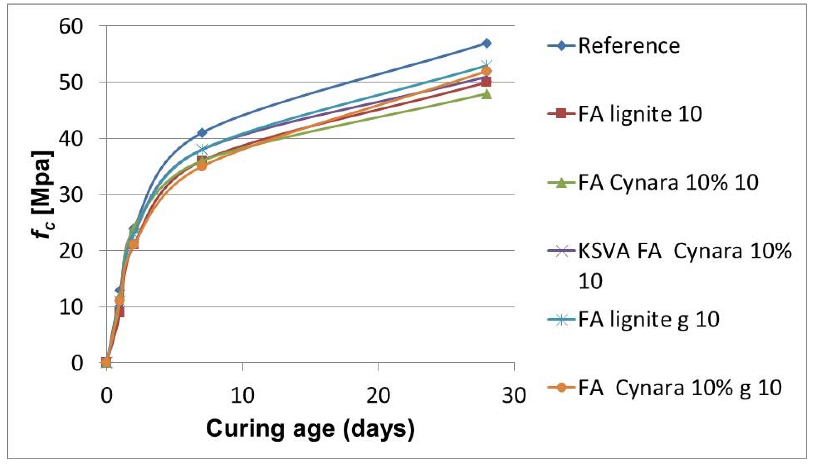
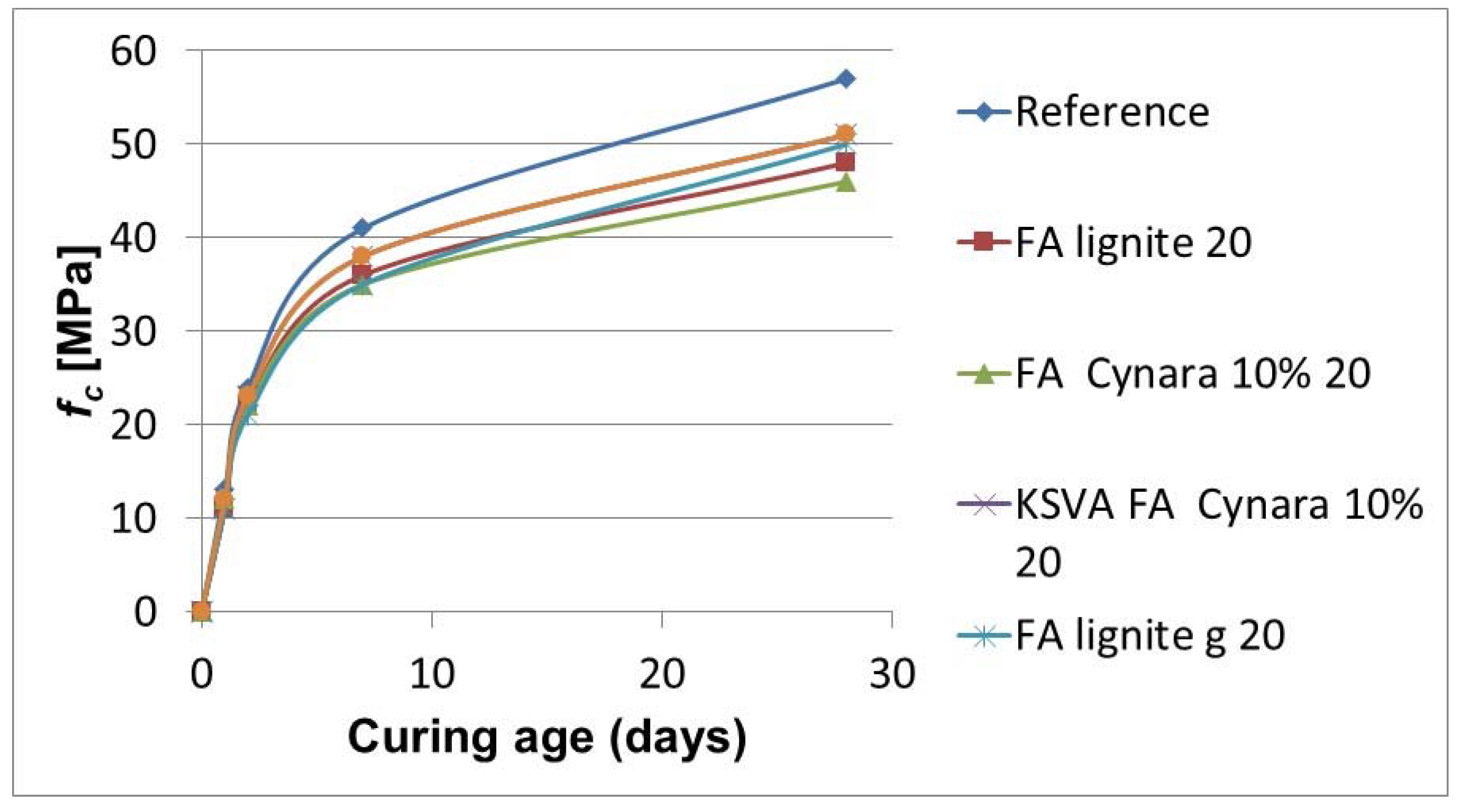
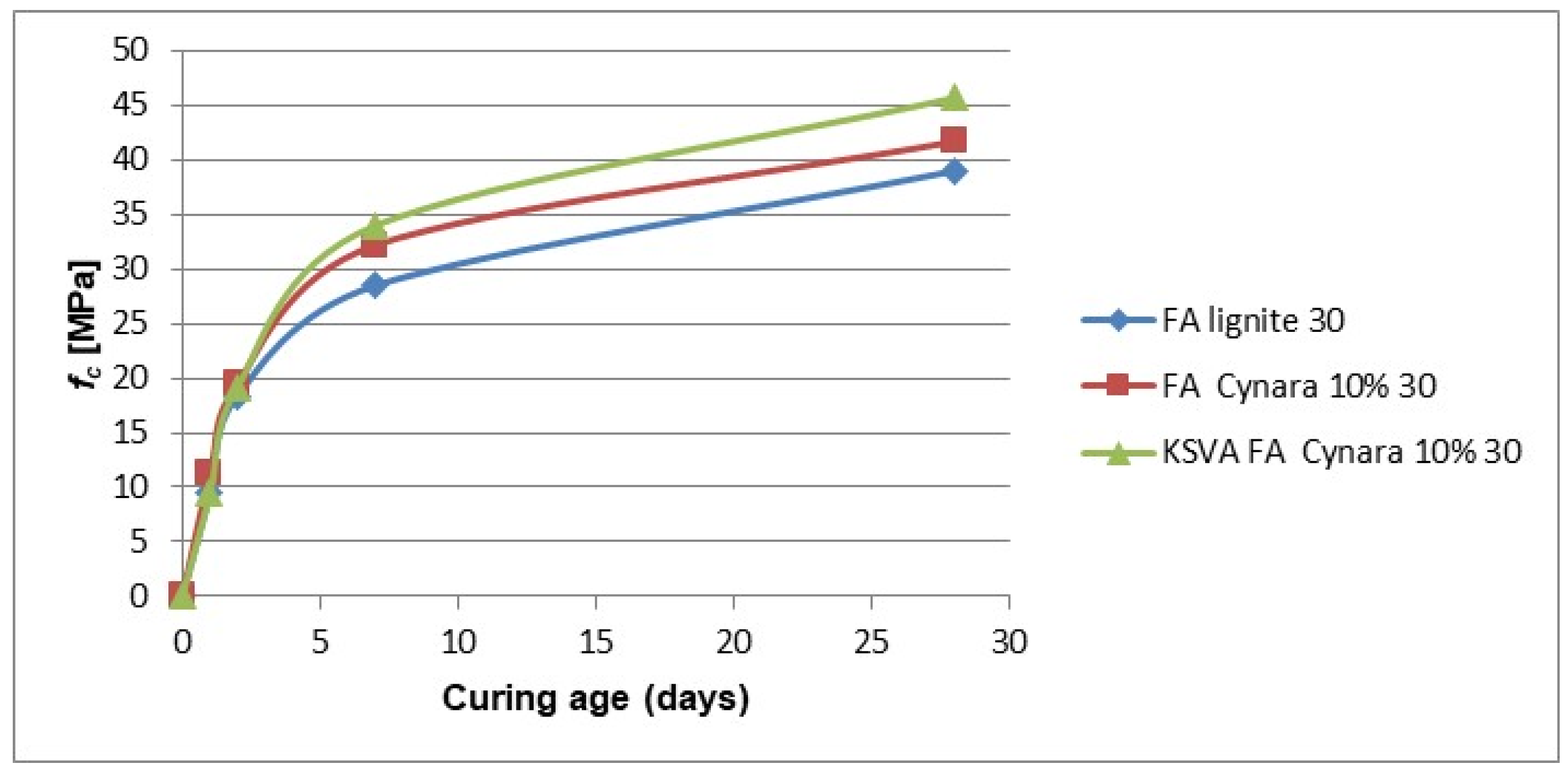
Fly ash was used to partially replace ordinary Portland cement in amounts of 10%, 20% and 30% by mass fraction. The compressive strength property was evaluated and determined according to EN450-1 following procedures in EN 196-1. The cured specimens tested were 40 × 40 × 160 (W × H × L) mm prismatic samples. The cured specimen was loaded until bending failure to obtain two halves. The two halves obtained were tested in compression until failure, and the compressive strength was determined according to (Equation (2)) below:
f c = F A
where, fc is the compressive strength, in megapascals [MPa]; F is the maximum load at fracture, in Newtons [N]; and A is the cross sectional area, in square millimeters [mm2]. Compressive strength was measured at various days from 1 day up to 28 days after curing of test specimens. The 28-day strength corresponds to about 80% of concrete’s strength under short-term loading [28].

3. Results and Discussion

3.1. Chemical Characterization of Fuels

Table 2 shows the fuels proximate and ultimate analyses. As expected, there were noticeable differences in the moisture and ash contents of the lignite and the volatile content of the Cynara.
The most noticeable difference of the fuels in Table 2 is that the herbaceous biomass has a significantly lower water content and ash yield, and a correlating higher heating value. The Cynara has a higher volatile content, about a 17% increase and a higher oxygen content. The Cynara in the fuel blend indicates a much-improved regulation of combustion.
The ultimate analysis shows that the percentage of hydrogen and elemental oxygen are higher and the carbon lower in the Cynara biomass when compared to the lignite. The lower value of nitrogen in the biomass shows that co-firing of Cynara with the lignite will have the advantage of reducing the stack emissions of the conventional pollutant NOx that is regulated. Also, the lower nitrogen content of Cynara means that co-firing may reduce the need for reagents to be injected into an selective non-catalytic reduction catalyst (SNCR) or high dust SCR equipment to reduce NOx emissions, if already occurring, which would decrease the propensity to absorb ammonia salt on fly ash (ammonia slip), as ammonia contamination of fly ash creates a host of potential odor issues when used in Portland cement-based projects [29].
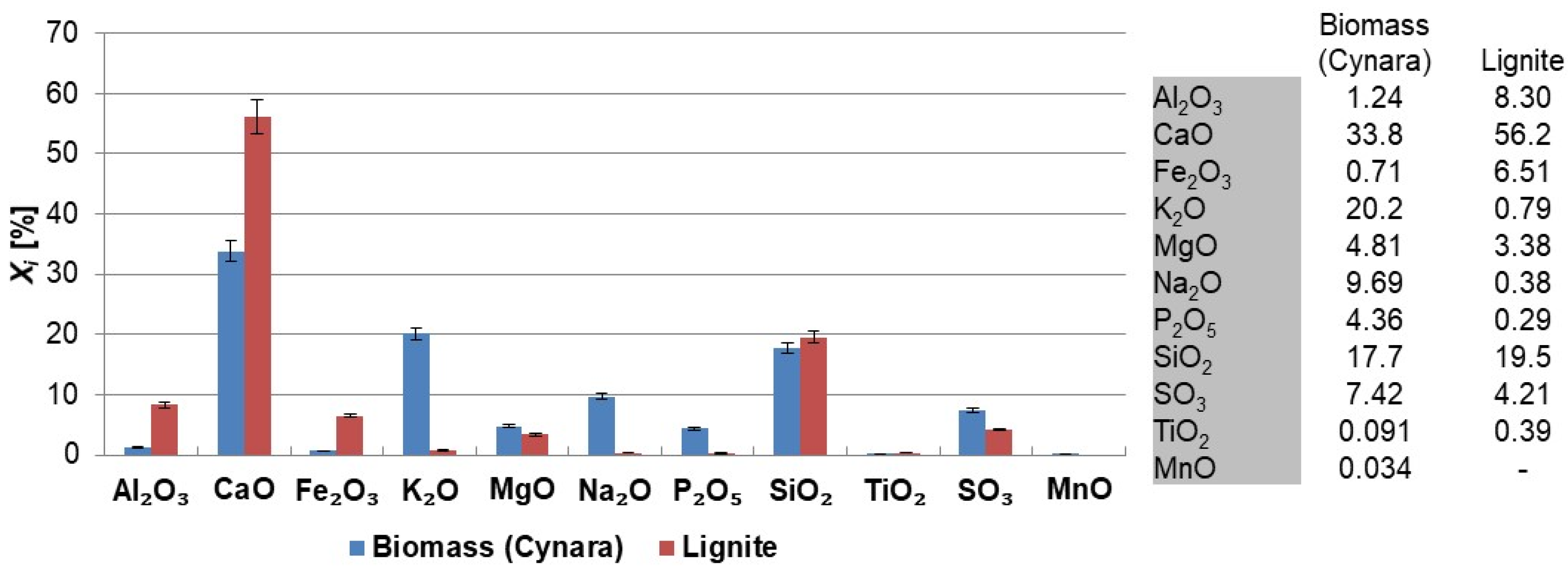
The calorific values illustrate the influence of the change in moisture content, and to a lesser extent, the volatile matter amount had on the heating value of the fuels. The net calorific value of the Cynara is comparable to the values measured for other biomass types [21]. Co-firing of the fuels would cause parameters to vary in proportion to their contribution to the fuel blend, e.g., energy and ash contents. Thus, the co-firing of Cynara with the illustrated lignite quality may not only lead to improvements in the combustion performance, but also potentially in the ash quality. Figure 3 shows the major and minor oxides of the fuels on a carbon free basis.
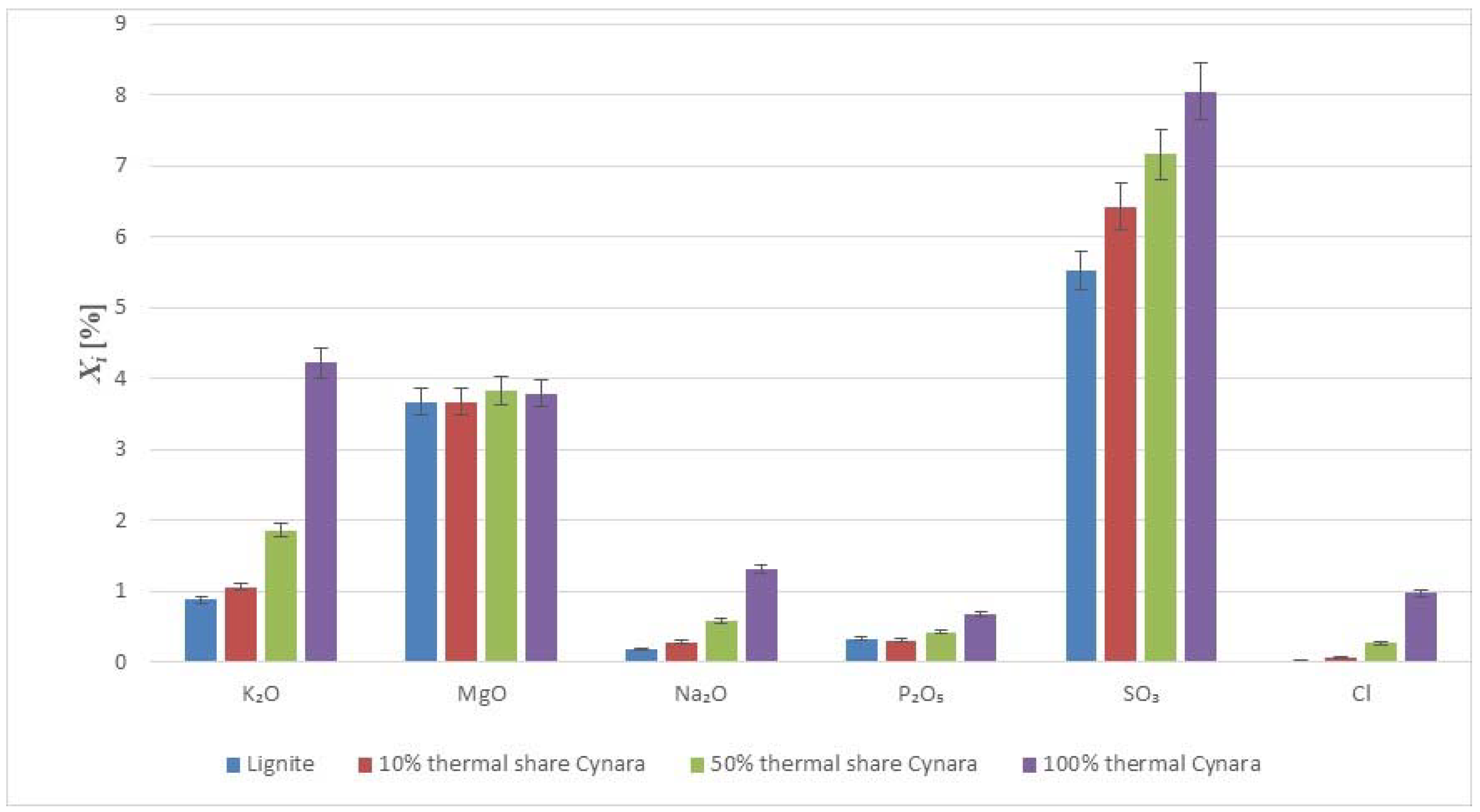
The herbaceous biomass has less CaO than the lignite, but more K2O, Na2O, SO3 and P2O5 contents. Generally, this trend is reported in literature for biomass fuels when compared to coal or lignite [30], except for the SO3 trend. The oxides of alkali, sulfur, and phosphorous are limited in concrete standards for applications in construction. However, when combusting the fuel with a lignite, having a significantly higher ash content, and at moderate thermal shares, the impact on the ash quality may be negligible too little. The SiO2 contents in the fuels are comparable. The silica value for the Cynara is aligned with values for herbaceous and agricultural biomass [30]. The SiO2 value in the lignite may reflect the quality from Greece, as the CaO oxide content is very high. Higher co-firing shares could change the ash quality for use in concrete, but masonry or mortar construction applications may be valuable options, as many of the concerns for concrete use with strict material provisions for conservative design are not warranted, and requirements are usually more performance based. Table 3 shows values for the major and minor elements in the fuels.
Most of the ash-forming elements in annual plant biomass are noted as nutrients required for plant growth with inorganic impurities, occurring as a result of biomass being contaminated with soil during collection or handling [31]. The diverse ash forming matter in biomass fuels depends on the biomass type, soil type, and harvesting conditions, with Ca, K, Na, Si and P being major ash forming inorganic chemical elements due to some of these needed as nutrients in biomass [32]. Potassium and phosphorous are primary plant nutrients while sulfur, calcium, and magnesium are secondary plant nutrients [33], so an increasing share of co-fired Cynara would likely produce an ash quality very suitable for uses other than concrete, such as in low technical demand masonry applications, e.g., trafficked areas, parking lots, and in soil amelioration applications too.

3.2. Ash Loadings (Removal Rate) Trend

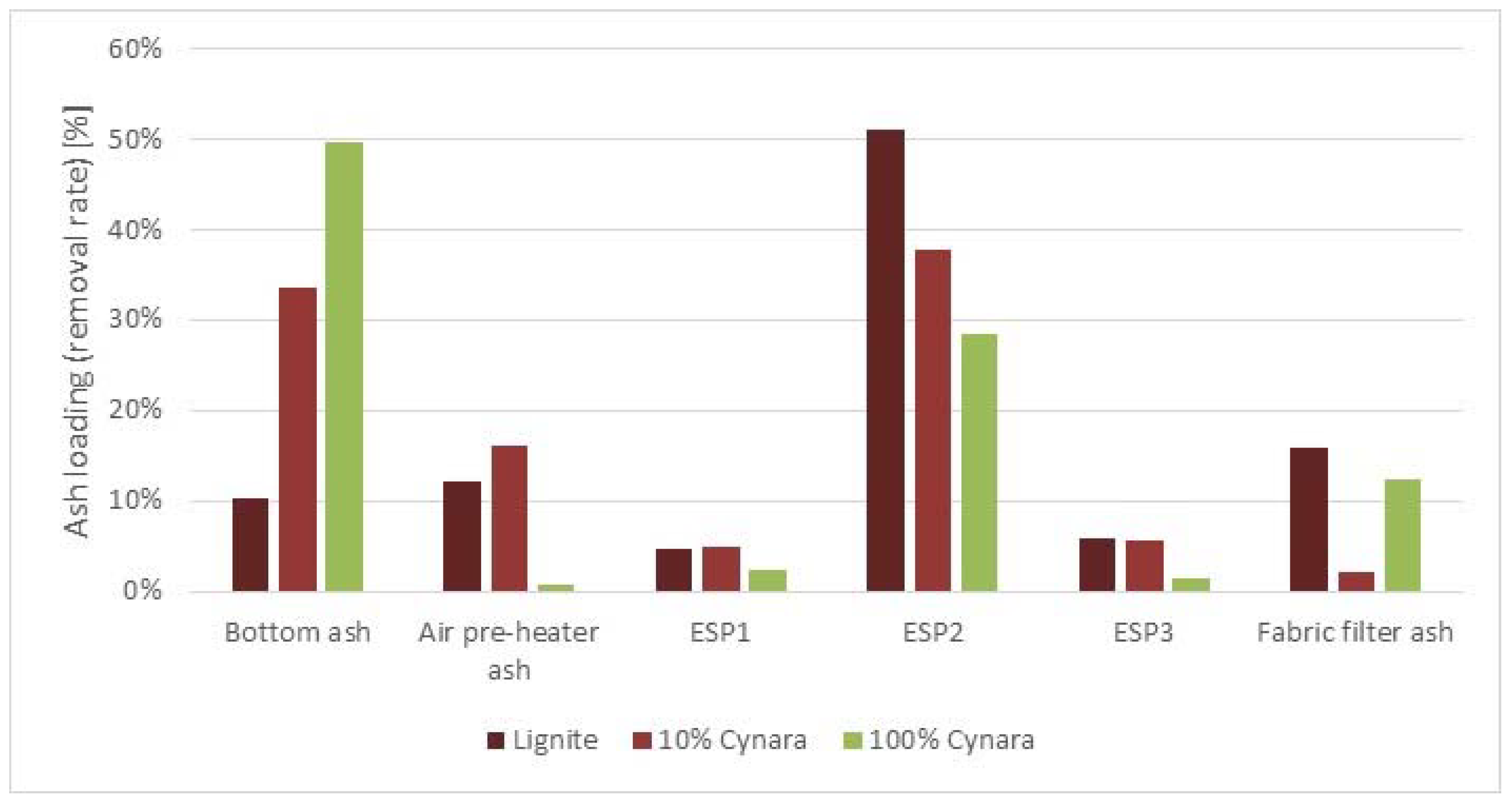
Ash was collected along the flue gas stream at different locations. The collected ash was completely weighted and finally related to the collection period for different scenarios. Figure 4 shows the different removal rates at the different collection points.
Based upon the operational design of the ESP, different size fractions are collected in the three hoppers. In the first ESP hopper, the largest ash fractions are collected. In the second ESP hopper, the middle size ash fractions are collected, which is about 80% of the total ESP ash. In the last ESP hopper, the finer ash fractions are collected, which is the least amount of the size fractions.
With the addition of Cynara in the fuel blend, there is an increase in fuel particle size distribution. Thus, the ash loading at the bottom of the combustion chamber increases due to the larger particles not being entrained in the flue gas stream exiting the furnace. Therefore, less ash is collected at points downstream the furnace. Consequently, there may be a significant increase in the bottom ash amount that needs to be addressed in the ash management procedures. There may be a need to find additional utilization markets for the bottom ash or apply post-treatment processes for utilization options.

3.3. Particle Size Distribution of Ashes

Fineness may be considered the most important property of fly ash in relation to its use in concrete, with the general rule the finer the better [16]. The fineness of fly ash used as part of cement mixtures influences the rate of hydration since hydration occurs at the interface with water [34,35]. The fineness mainly impacts the short-term strength and only slightly affect the long-term strength [36], which is due to the proposed occurrence of a more uniform microstructure expected for an increase in fineness [35]. The pozzolanic quality of fly ash correlates to fineness and its glassy content (amorphous matter) [37]. The strength increases as the granular distribution become narrow, which is predominantly an effect of a faster hydration under the conditions [35].
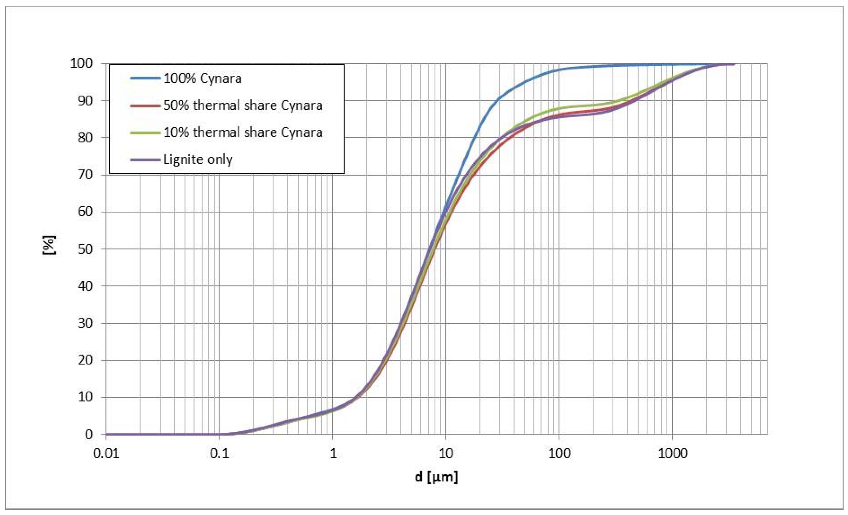
Compared in Figure 5 is the particle size distribution (PSD) of the representative bulk fly ash samples from each Cynara experimental trial. The pure Cynara combustion fly ash is noticeably finer than the other ashes, while the other co-firing cases are similar to the lignite case.
The comparability of the co-fired fly ash particle sizes to the lignite case may be attributed to the percentage of Cynara ash being much lower in the fuel mixture. In Table 4 is shown the size distributions for D10, D50 and D90 values.
The particle size distribution of the co-fired ashes are similar to the lignite case, and the D90 value is improved. Thus, the ash reactivity is not negatively affected by the increased Cynara thermal share in the fuel blend, regarding particle size distribution. The particle size is the most important physical characteristic determining the reactivity of fly ash [3]. Fly ash particles in the range of 10 μm to 50 μm mainly are void-space fillers in concrete and particle sizes smaller than 10 μm are classified as pozzolanic reactive (hardening when reacted with Ca(OH)2) [3]. Thus, the larger biomass fuel particle size should not lead to reductions in the ash reactivity from the particle size distribution.
With the higher heating value of the Cynara fuel, it is likely a rise in temperature may have contributed to improvements in char and mineral fragmentation and ultimately smaller particle sizes for the 100% Cynara test scenario compared to the other cases. Furthermore, the alkali species are known to lower the eutectic temperature of compounds [38] creating melts, which would be enhanced with the increase in the furnace temperature, and this likely creates an improved thermal contact due to melting of alkali compounds that enhances the heat transfer rate to other compounds [23], e.g., via heterogeneous condensation. The Cynara ash had much more K2O content than the lignite. Thus, the herbaceous biomass fuel likely had a better particle fragmentation throughout the burning process. This would likely contribute to a finer particle size distribution of the fly ash produced from that test scenario. This needs further studying.
The very close gradation curves of the fly ash from the co-fired Cynara tests compared to the lignite fly ash indicates no negative concerns for water requirement or cohesiveness of the fly ash from Cynara in the fuel blend. The particle size distribution actually got somewhat finer with the 10% co-fired share of Cynara. This slight change in fineness indicates a possible improvement in the workability when used in mixtures, as finer round shape particles can reduce the friction between ordinary Portland cement particles and among fly ash particles [10].
It is believed that the D90 value for the 10% Cynara is caused by imperfect mixing of the ash before determination of the D90. The ash formation for the co-firing of Cynara is believed to be driven by the ash formation from the lignite, i.e., mineral fragmentation, coagulation, agglomeration, heterogeneous condensation, etc. Also, the burning of pure Cynara, which has much lower ash and fixec-carbon contents along with a higher volatile matter amount, due to evaporation of alkali compounds and other organic matter the ash is finer. The PSD from the pilot-scale tests were compared to results from industrial experimental tests. This supports evaluations for the scale-up of pilot-scale test results. The industrial tests were conducted at the Kardia Power Plant located in Ptolemedia, Greece, and is described in the literature in [39]. Table 5 shows those comparisons.
Table 5 shows a good correlation among the particle sizes from the pilot-scale fly ash and the industrial ground fly ashes. The pilot-scale results are very close to the ground industrial fly ashes, which is a practice in the industry. Thus, the pilot-scale observations can be considered to be transferable to industrial scale, regarding the PSD of the fly ashes, which has a very significant impact on the reactivity of ashes, and is one characteristic relied upon to assess fly ash pozzolanic behavior.

3.4. Chemical Analysis of Ashes

3.4.1. Chemical Composition of Fly Ashes

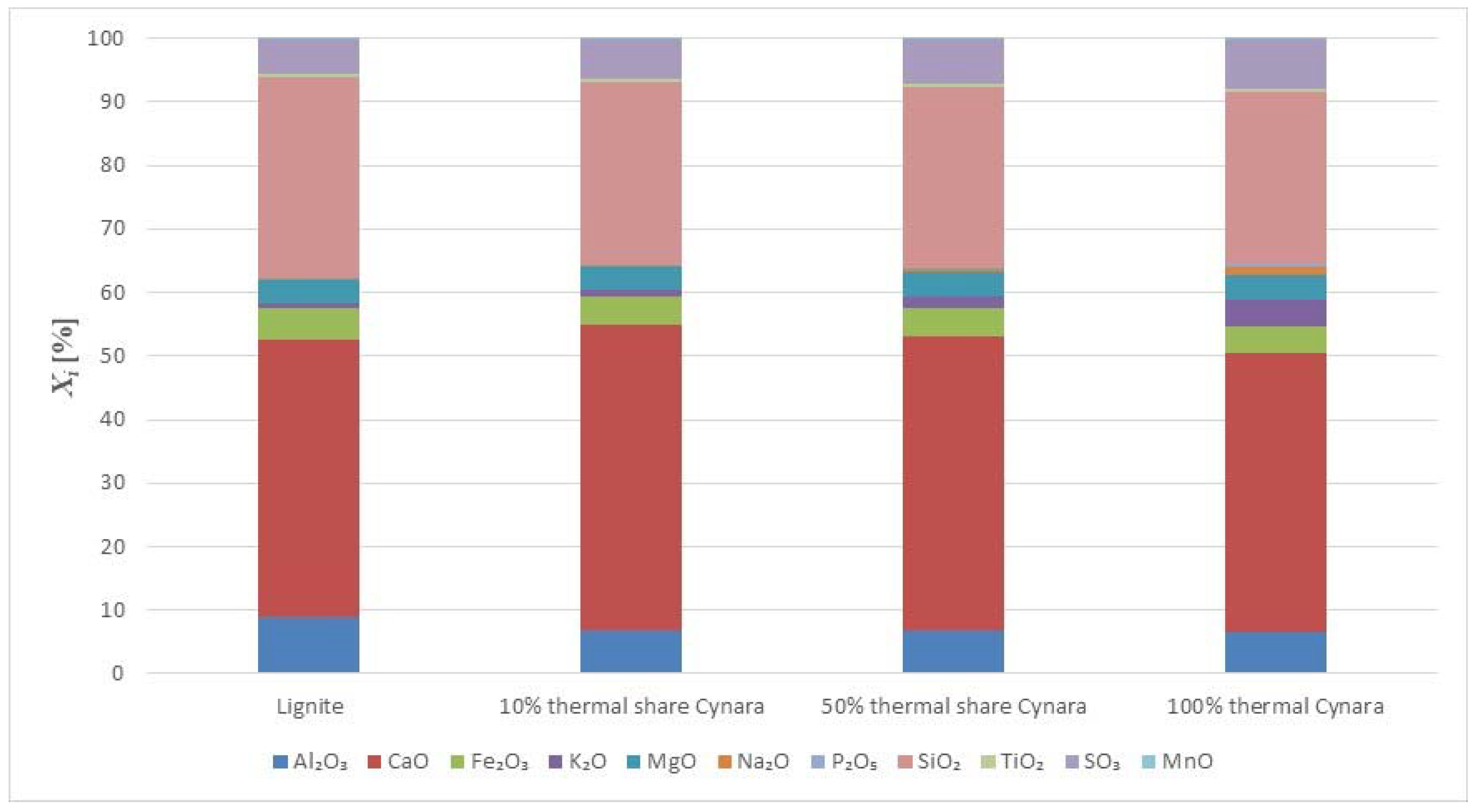
Figure 6 and Figure 7 show the chemical analysis of major and minor inorganic contents in the ashes. The trends are as expected.
Fly ash generated from combustion of lignite is a calcareous fly ash (sulfur-calcitic fly ash) mostly comprising chemical components like silicates, aluminates, calcium oxide, and sulfates [40]. Generally, compared to coal ash, biomass ash from natural biomass usually are enriched in descending order in K, P, Cl, Ca, Na and Mg and depleted in descending order in Al, Ti, Fe, Si and S [30]; however, this may not be the case for certain biomass fuel qualities, so it is only a guideline. The Figure 6 and Figure 7 above show that the co-fired ashes had increased oxide concentrations of K2O, P2O5, Na2O and CaO while having depletions in oxides of SiO2 and Al2O3. The majority of the trends in the ash oxides in this study are supported by results noted in the literature.
The most noticeable change in the oxides with an increasing thermal share of Cynara reflect the contribution of each fuel in proportion to their percentage in the fuel feed blend. Those are expected based on the fuel properties. Otherwise, the oxide contents are comparable for each test case. So, for average lignite fly ash uses, a high co-fired thermal share of Cynara, up to 50%, in the fuel blend does not potentially alter any market applications practices for ash utilization, despite the increased amount of problematic species in the Cynara. The seemingly acceptable fly ash quality up to 50% thermal share of Cynara may be due to the much lower ash content in the fuel along with the higher calorific value of the fuel and the higher ash content of the lignite.
Fly ash quality concerns could be the increasing contents of alkalis and sulfur and the reduction in alumina and silica. Silica and alumina along with iron oxide comprise the total oxides in EN 450-1 to be greater than 70% on a mass basis [41] to ensure a good pozzolanic reactive fly ash. For lignite ashes, the summation is greater than 50% on a mass basis according to ASTM C618 to ensure a good reactive lignite fly ash.
The most common form of chemical attack in concrete is sulfate attack, leading to erosion of the concrete that can be caused by sodium sulfate, potassium sulfate, calcium sulfate, magnesium sulfate, etc. [42]. Sulfate SO3, can cause long-term expansion [43] from sulfates reacting with calcium hydroxide released during hydration and with calcium aluminates in the cement [44]. The sulfate reactions create a range of sulfate compounds (e.g., sulfur-aluminates) that occupy a greater volume than the original concrete components, causing expansion and eventual failure of the concrete [44]. The SO3 content for coal fly ash is limited to 3% by mass in EN450-1 for use in concrete. So, there is a potential need to consider the impact of the sulfur content on possible uses involving construction applications with concrete. Meanwhile, ageing (both hydrated and naturally aged fly ash) comprises mineralogical changes in the fly ash that may include reactions as oxidation, carbonation, neutralization of pH, dissolution, precipitation, and absorption, towards the formation of stable secondary minerals [45]. Soluble salts concentrations and trace elements decreased in fly ash due to weathering (aging) during natural leaching that mitigated their detrimental effects over time [46]. Thus, allowing fly ash to undergo aging (maturation) would lead to lower sulfur contents, improving its quality. On the other hand, if there is an increased sulfur amount combined with calcium, i.e., anhydrite (CaSO4), in the fly ash, the mineral is very active [30], which is desirable in masonry and other low technical utilization market applications.
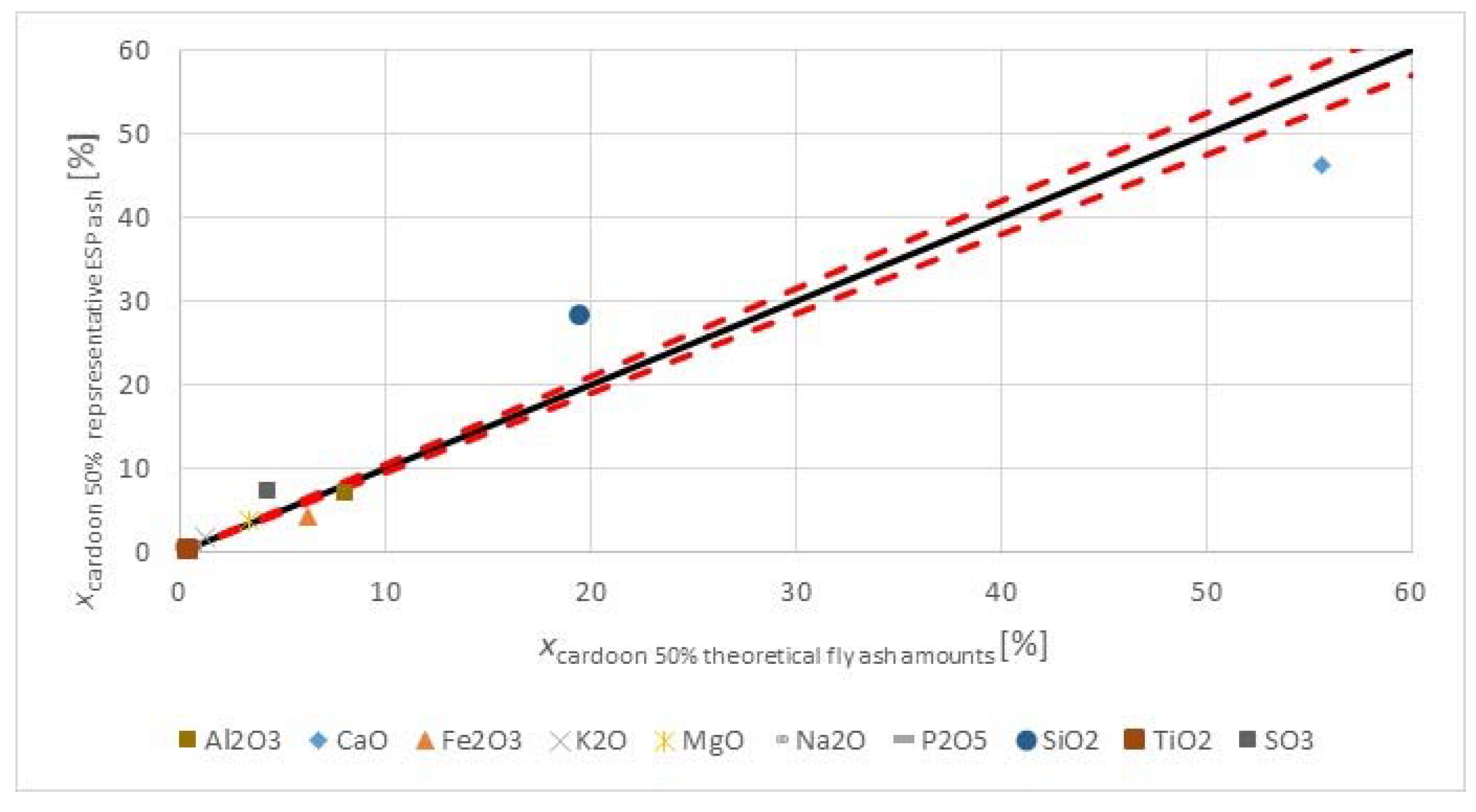
Alkalis (i.e., alkalis (K2O and Na2O), as sodium oxide equivalent) limits are stated to minimize the effect of alkalis reacting with aggregates, containing a reactive form of silica (alkali-silica reaction, or ASR), in the presence of moisture [47]. The reaction under those conditions produces a gel that can absorb water and swell, generating a pressure that causes expansion and cracking [47]. The alkali content is below the 5% by mass limit for coal fly ash as stated in EN 450-1 for concrete use. So, despite the high potassium content of the biomass, the fly ash quality did not have an adverse impact regarding unwanted alkali levels. Theoretical fly ash oxide calculations, assuming 70% of fly ash collection in the ESP as 5% each goes to the economizer ash and air pre-heater ash [48], were near to measured values, excluding the pure Cynara combustion.
The chloride contents in the lignite, 10% Cynara, 50% Cynara and 100% Cynara thermal share ashes were 0.0025%, 0.0061%, 0.026% and 0.097%, respectively, on a mass basis. Chloride can lead to corrosion of steel reinforcement in concrete [47], which is used to provide concrete with tensile strength [47]. That occurs due to Cl ions undermining the protective effect of passivation and encouraging the process of corrosion in concrete [49]. The values in the tests are below the 0.1% by mass in EN 450-1 for coal fly ash. With pure Cynara combustion unlikely to be practiced in large boilers, e.g., 300 MW, due to reasons of logistics, e.g., fuel supply, milling, feeding, storage, etc., the possible amount co-fired share of Cynara, 10–50% on a thermal share basis, does not lead to an adverse fly ash quality regarding chloride content.
The loss on ignition (LOI) used to assess the unburnt carbon in ash for the lignite, 10% Cynara, and 50% Cynara thermal share ashes were 9.48%, 14.64% and 13.7%, respectively. In biomass combustion, most of the mass is lost during devolatilization with char formation being only about 10% and unburned carbon in ash is not such an issue [50]. The occurrence is the opposite during the co-combustion trails observed. So, the increase in the LOI with co-firing is likely impacted in a similar manner in this work. In EN 450-1 the maximum LOI limit on a mass basis is 9%. The high values indicated in these tests would likely warrant concern for various reasons. High LOI values hinder the strength gain in concrete [47] and require the use of more water in concrete mixtures [32]. Higher amounts of carbon have a propensity to adsorb significant quantities of water and specialty surfactants or chemical admixtures in concrete (e.g., air-entraining admixtures (AEA), water-reducing admixtures, and retarders) [32]. Also, high carbon content can result in discoloration of the hardened concrete and to mixture segregation [51,52]. However, industrial technologies have been developed to reduce the carbon content in fly ash. Commercial practices include sieving, thermal post-treatment of fly ash [52], triboelectric separation [52,53], froth flotation [53], and re-burning [54]. So, increased carbon concerns can be mitigated, improving the marketability of the ash.
The chemical composition of the fly ashes are comparable and very near to lignite fly ashes successfully tested in a blend of fly ash and waste glass, 60% and 40%, respectively, to produce lightweight aggregates [13]. Thus, the production of successfully performing lightweight aggregates from the fly ash qualities produced is a very relevant utilization option that requires further studies. Also, the high Ca content along with the Si content in the fly ashes make them suitable for studies of high calcium fly ashes in aluminum based metal matrix composites. Work done has revealed that the strengthening of aluminum alloys with fine ceramic particles (such as fly ash) strongly increases their potential in wear resistance and structural applications [14].

3.4.2. Mobility of Some Species

Fly ash disposal is associated with ecological risks due to acidification and the infiltration of heavy metals and radioactive components that can be released into the soil [55]. The environmental impact of fly ash, either used in an application or sent to a landfill depends to a large extent on the mobility of the polluting components in the ash [16]. The subject of leaching behavior and mobility of elements in co-combustion ashes is less common, resulting in not many works dealing with the topic [56]. Biomass ash does not contain the toxic metals like in coal ash [32]. One problem with biomass ashes is attributed to the fact that trace elements are in more mobile compounds, where the fraction can be up to 61% more in biomass ash compared to 0.2% to 7.2% in coal ashes [57]. Table 6 shows the influence of an increasing co-firing share on the mobility of some nutrient element species and some heavy metals in the fly ash. Values for Cu, As, Pb, Ni and Cd were below the detection limit of the equipment used.
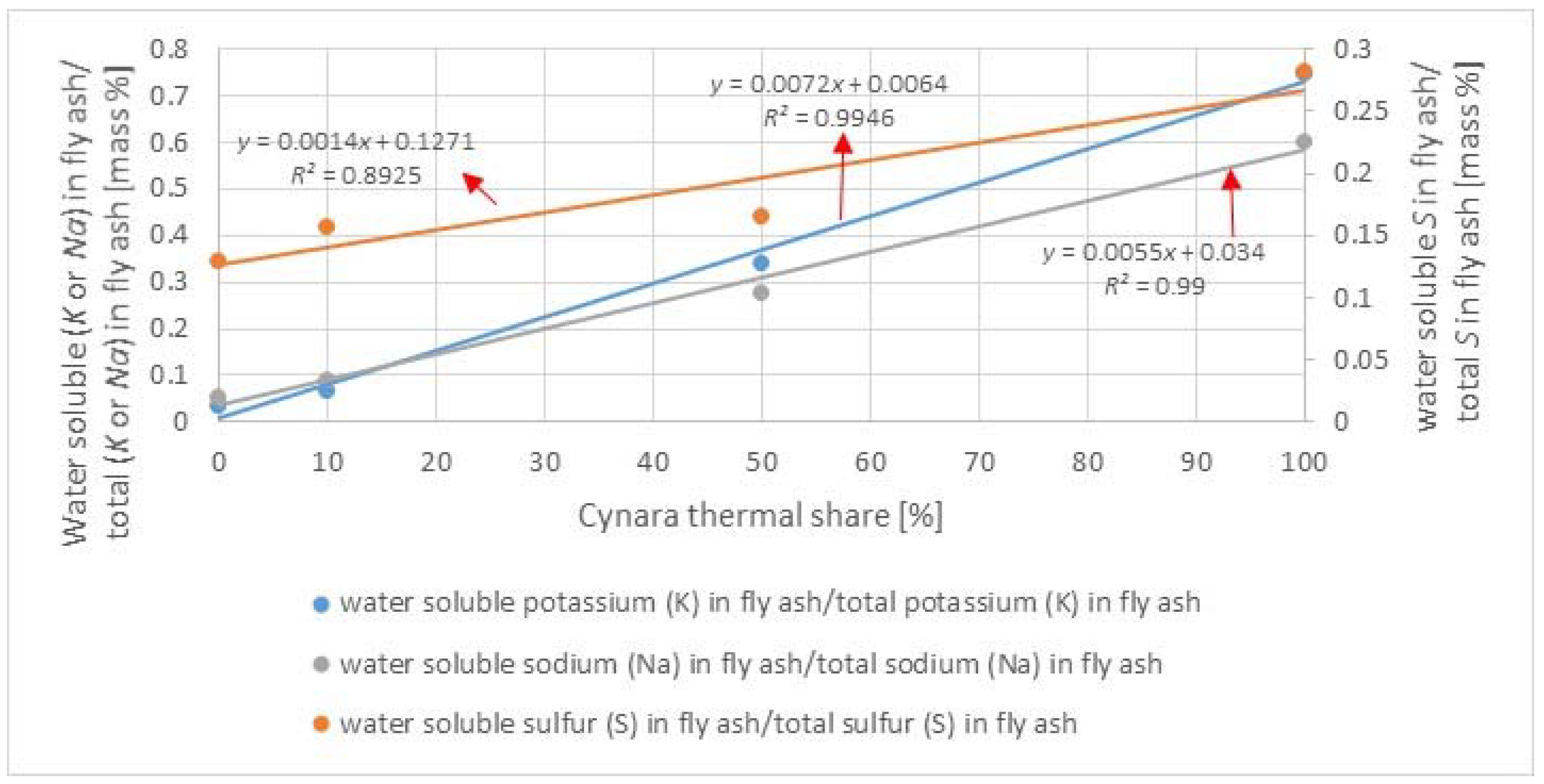
Table 6 shows that the increasing co-fired share of Cynara did not lead to a significant increase in the mobility of trace elements observed. Heavy metals are correlated to the ash content of a fuel, a higher ash content mean higher levels. The lignite had considerable higher amounts of heavy metal elements than the Cynara. Cr increased in the fly ash with higher co-firing shares of Cynara, which is an widely known occurrence in wood combustion. It is likely that the association of Cr is more organic in biomass fuels, causing higher mobility, or catalytic effects occur from other biomass species, or changes in ash compounds impacting mineral phases that effect the mobility of Cr. There is the possibility of Cr being introduced from the pelletizing process that contributes to the Cr level observations in biomass combustion. Further work on the issue would clarify the cause. On the other hand, from the results observed, environmental concerns of the fly ash quality from co-firing of Cynara probably would not be warranted. The leachability of sulfate, chloride, sodium, and potassium increased correspondingly to the Cynara thermal share in the fuel blend. Those increases suggest more soluble salts concentrations in the fly ash. Regarding potential soil applications, high soluble salt levels in a green fly ash could limit its use, as an increase in the ground salinity is harmful to a successful re-vegetation goal [58]. Excessive salts in the soil reduce the water potential for plants causing water stress in the plant due to the ground becoming more saline and ceasing to support agricultural production [59]. On the other hand, the bioavailability of nutrient species is a concern. With increases in the co-firing share of Cynara, the results show that there is qualitatively a high potential of K being available for uptake as a nutrient in soils, and along with no negative impact from the majority of heavy metal leaching results, this is added value as a soil ameliorant on a qualitative basis. The observances indicate that at the 10% and 50% co-firing shares of Cynara produce fly ashes of sound environmental and ecological qualities. Figure 8 highlights the potential impact of increased thermal shares on the potential availability of some elements.
The regression observations reveal that the soluble fractions of potential soil nutrients were significantly associated with an increasing share of Cynara in the fuel blend. Therefore, there is a high potential of the co-fired fly ashes, when used in combination with organic materials, to substantially improve soil properties. Organic composts with high organic carbon and micronutrients in combination with nitrogen fertilizer and fly ash, lead to improved soil properties and slowly released nutrients in accordance with the demands of growing crops; the blended materials lead to reduced bioavailability of metals supplied by fly ash too [12]. The increased soluble fractions of the basic elements, K and Na, with increasing Cynara co-firing shares would raise the pH of the fly ash. Biochar combined with a lignite fly ash and applied as an amendment to an acidic soil lead to improved soil parameters, e.g., pH, microbial biomass carbon, etc. [12].

3.4.3. Enrichment of Major and Minor Elements

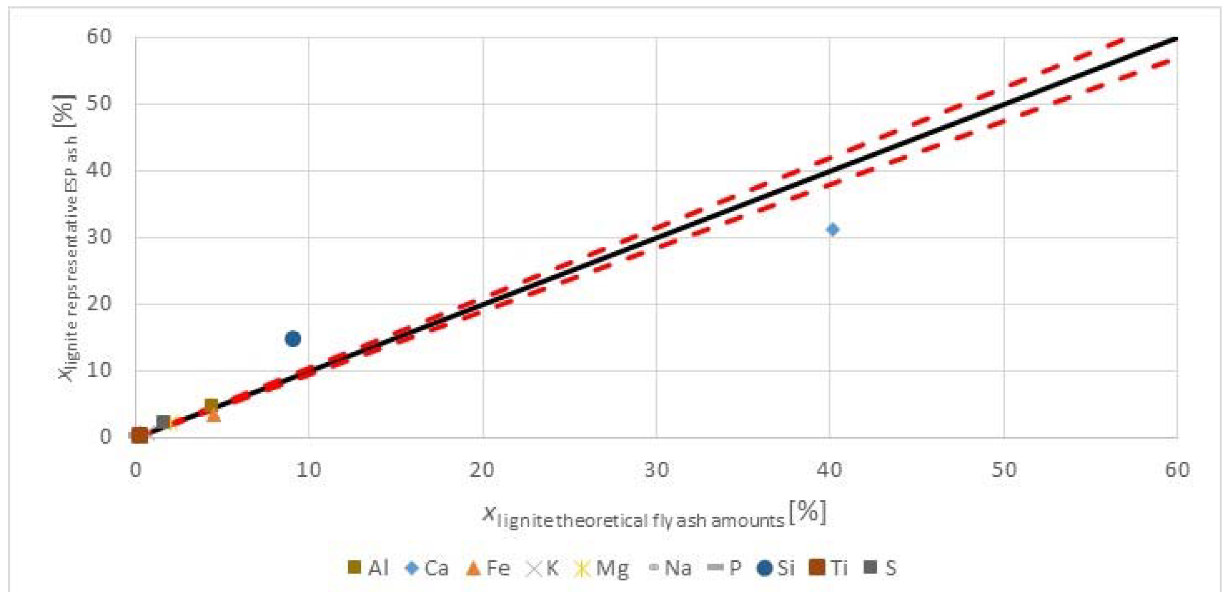
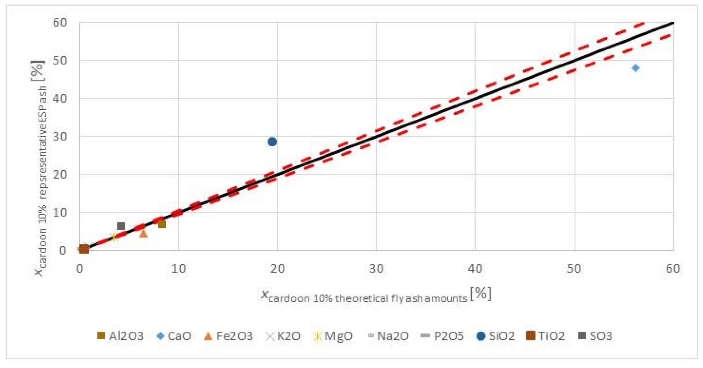
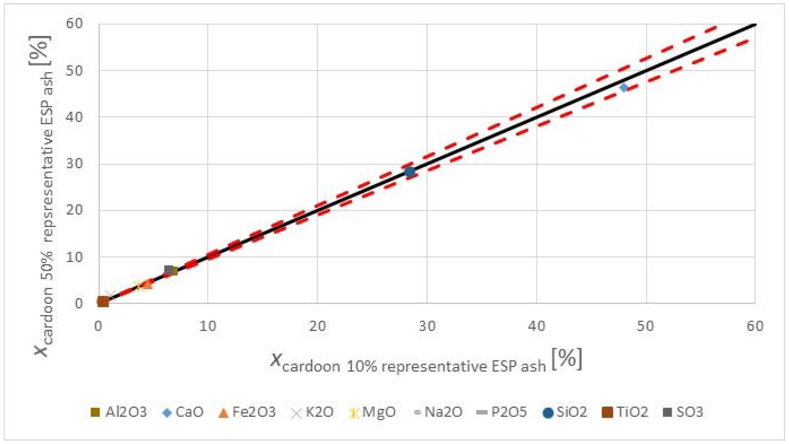
When coal is combusted, a concentration process occurs, which can result in the ash element concentration being higher than those in the coal [16]. During the cooling of the flue gas along the path to the dust removal facility (from approximately 1600 °C to 140 °C) the dew point will be passed an condensation will begin on the surface of fly ash particles [16]. Elements in the ash after combustion can be enriched, depending on the type of ash and the particular element [16]. Figure 9, Figure 10, Figure 11 and Figure 12 show the enrichment of major and minor elements in parity diagrams for the lignite, 10% thermal share of Cynara, 50% thermal share of Cynara, and 100% Cynara combustion, respectively. The effect of the higher heating value of the biomass and the high ash content of the lignite is observable.
All fly ashes are shown to be enriched in Si. All fly ashes had a slight, comparable enrichment of sulfur. All fly ashes, excluding the 100% thermal share of Cynara, are shown to be depleted in Ca. The 100% Cynara combustion scenario produced fly ashes enriched in the refractory elements, but significantly depleted in the elements K, Na and P, which is an unexpected observation.
Ca is among the group of elements considered not volatile [16] that can condense on bottom ash particles. The group of compounds containing calcium are noted to not vaporize during combustion and their concentration, i.e., enrichment, generally, is considered the same in all ash types and is independent of size [16]. The enrichment factors of Ca for the bottom ashes were 0.78, 0.63 and 1.2 for lignite, 10% Cynara thermal share, and 100% Cynara, respectively. Those observations correlate to the fly ashes. With the introduction of biomass in the fuel blend, the combustion behavior was improved, which may have led to more Ca being volatile or the association of calcium in biomass fuel makes it more volatile than in coal, e.g., organic associated, etc., rather than clay associated. However, the enrichment of Ca is apparently the same in all ash types, as is the case reported as noted above. The depletion of K, Na and P in the fly ash could be a result of their more volatile nature in biomass fuels and along with a reduced Si content, which may contribute to more calcium sulfate compounds being formed, can lead to a lower heterogeneous condensation of those species. Thus, they remained in the vapor phase after the primary dust collection point (electrostatic precipitator), leading to fly ash enrichment factors being low (<<1), and are collected with the finer dust particles (fabric filter) and emitted to the stack. The enrichment factors for K, Na and P in the fabric filter were 0.86, 1 and 0.23, respectively. This indicates that most of K and Na was captured in the fabric filter, but P was emitted via the stack.
The interactions of the co-fired fuel ashes resulted in the much higher contents of problematic species (K, Na, P, S), for ash behavior in a pulverized fuel facility, not being a significant concern in the Cynara for the fly ash quality. Calcium and magnesium, which do not condense of bottom ash particles, may react with alumina and silica not condensed on bottom ash particles. The reaction of calcium with alumina silicates (Equation (3)) and silica (Equation (4)), as in the addition of an alumina-silicate additive in the fuel blend in the gas phase is shown below [7]:
CaO(s) + SiAl2O5 → CaAl2SiO6
CaO(s) + SiO2(s) → CaSiO3
Thus, the above mechanism may have contributed to enrichment of silica in the fly ashes. This may have contributed to more volatile species leaving with stack emissions or collected in ash deposition within the boiler in other compounds besides silicates.
The increase in SO3 in the co-fired ashes is a trend that is not usually found in increasing co-firing shares of biomass. Co-firing of natural gas with coal can lead to increases of sulfur retained in the ash. It was reported that from a field test of co-firing natural gas with coal, SO2 levels showed a 18% reduction for 11% gas co-firing [60]. It was believed that a mechanism exists wherein there is a shift of fuel sulfur conversion from SO2 to SO3 with gas co-firing [60]. This would lead to more alkaline species reacting with the SO3 to form sulfates. Also, co-firing of natural gas may increase the reactivity of sorbent metals in the fly ash due to a combination of activation and increasing ash surface area [61]. Because of the formation of oxygen radicals a natural gas flame may lead to higher concentrations of the more reactive and easily captured SO3 species above equilibrium levels [61]. In addition, the flame from gas co-firing may led to an increase in the heating rate of coal particles, which increases the internal surface area, causing a higher reactivity [61]. Mechanisms of formation of super-equilibrium concentrations of SO3 when SO2 is exposed to a hydrocarbon flame is due to excess O2 forming oxygen radicals (Equation (5)), and the oxygen radicals combining with SO2 to form SO3 (Equation (6)) [61]:
O2 + M → O + O + M
SO2 + O + M → SO3 + M
where M equals metals. Because of the relatively slow reaction rate of (Equation (7)), SO3 concentrations remain at super-equilibrium levels for several hundred milliseconds after the sulfur gas passes through the flame, despite once sulfur gas has passed through the flame, the SO3 concentrations begin to decrease via reaction with the oxygen radicals (Equation (7)) [61]:
SO3 + O → SO2 + O2
Previous tests showed that without co-firing of methane, the measured sulfur in the ash was 6.4% of the original amount in the coal, but with 4% methane addition, the measured sulfur in the ash was 58.4% of the original sulfur in the coal [61]. Therefore, it is believed that an effect of the natural gas co-firing was more calcium reacting with sulfur in the furnace, causing less sulfur available for reactions with volatile species in the cooler areas, i.e., convection pass. This may have contributed to no enrichment of the alkali species and P in the fly ashes, albeit the undesirable concentrations in the Cynara. There may have been positive synergistic effects between calcium reacting with alumina-silicates or silicates and afterwards with sulfur that led to no enrichments of the volatile species in the fly ash Thus, an optimized co-firing scenario of a low-quality lignite and an herbaceous biomass may be with the addition of natural gas. Further work is needed to elucidate the observations.
Thus, it is apparent that the use of natural gas enhanced the desulfurization from calcium in the reactor, as sulfur is among the group of elements that are the most volatile and expected to not be enriched in fly ashes [16]. The critical temperature range of sulfur reaction with calcium is 900 °C to 1250 °C with the lower limit being 870 °C to 900 °C and unstable above 1250 °C [62]. With the use of natural gas, there may be a longer temperature time history at higher temperatures in the boiler and higher kinetic reaction rates. It was reported that tests done with gas co-firing led to slagging, which heat transfer models reveled that an increase in the combustion zone temperature of approximately 38 °C and the flue gas exit temperature of about 7 °C could have contributed to the problem [60]. In this work, for example with a power output of 300 kWel, for a 10% thermal share of Cynara and with the lignite considered to be pre-dried to a 15% moisture content, air pre-heated to 200 °C, and an excess air ratio of 1.2, the adiabatic flame temperature was calculated as approximately 1720 °C. With the use of natural gas at a 20% substitution of the heat rate, the adiabatic flame temperature was calculated as approximately 1840 °C. Thus, the use of natural gas in the co-firing fuel blend would increase temperatures, potentially allowing for a longer time at higher temperatures and reactions of calcium with more sulfur oxidized to the more reactive SO3 species.
In the temperature range of 1700 °C to 1300 °C potassium species can react with alumina and silica to form potassium alumina-silicates, and the reaction dominates over sulfating reactions of potassium [7]. However, available Ca and Mg takes precedence with silica and alumina for reactions, limiting available species for reactions with potassium [7]. Potassium sulfate is expected to nucleate at about 800 °C [63] and sulfating potassium reactions are favored at low temperatures in the range 800 °C to 900 °C, and they are very slow below 800 °C [64]. However, all potassium is predicted to appear as K2SO4 below 700 °C [7], so the lack of enrichment of potassium in the fly ashes, when compared to the fuel content, especially for the pure Cynara tests, supports the assertion that the natural gas in the fuel blend created gas atmospheres favoring reactions of sulfur with calcium. Therefore, it is believed that the natural gas co-firing led to higher temperatures and more sulfur being captured by calcium in the higher temperature range. This would reduce the sulfur available for forming lower temperature compounds with K, Na, etc. Figure 13 compares the enrichment of elements in the fly ash in the 10% thermal share of Cynara scenario with the 50% thermal share of Cynara case.
The above Figure 13 shows that despite the unusually high contents of K2O, Na2O, P2O5 and SO3 in the biomass fuel, especially compared to the lignite, there was no change in the fly ash quality between a 10% thermal share and a 50% thermal share of Cynara. Along with the impact of natural gas, this may be attributed to the higher heating value of the biomass fuel, requiring much less mass for a thermal share substitution, which allows the ash in the lignite to have a relevant influence on the ash formation process. Thus, there is an apparent benefit of co-firing natural gas with a low quality lignite and an herbaceous biomass fuel. However, this has to be thoroughly assessed for the impact on boiler efficiency from the heat of vaporization of the hydrogen in the natural gas fuel and the higher cost of the premium fuel that can make it expensive during winter months [60].

3.5. Scanning Electron Microscope (SEM) Analyses and EDX Results

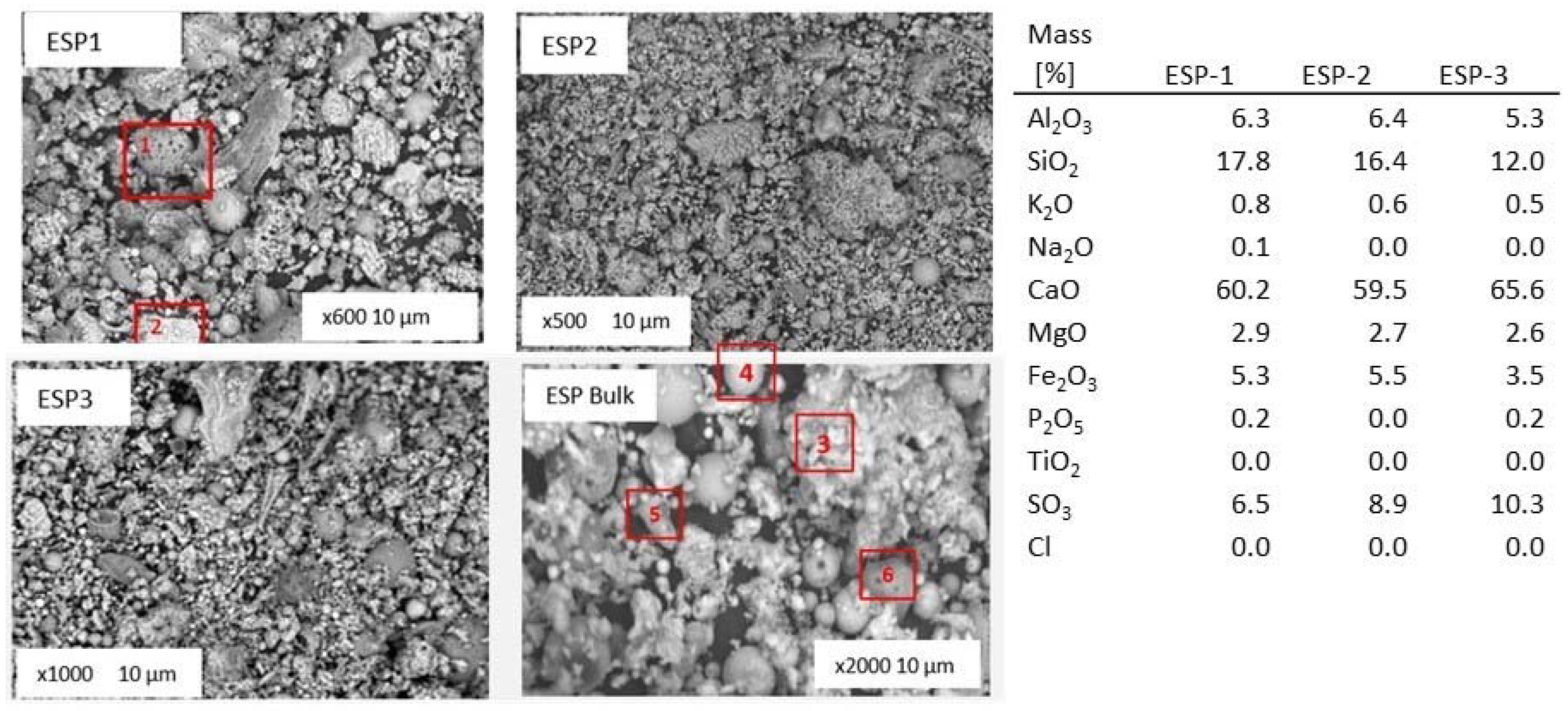
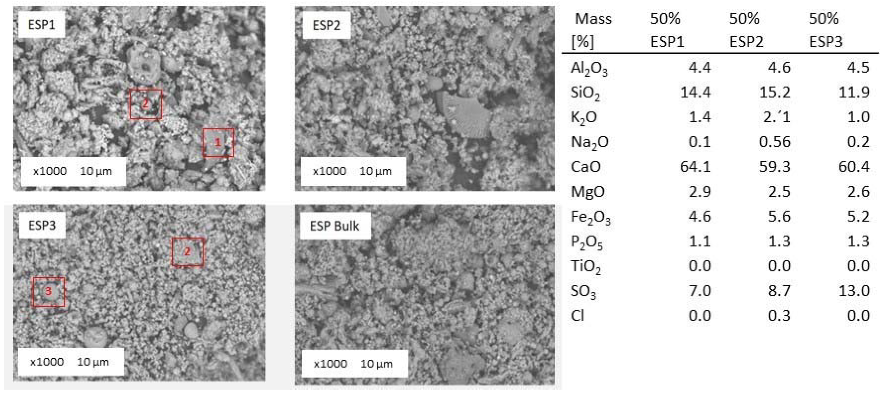
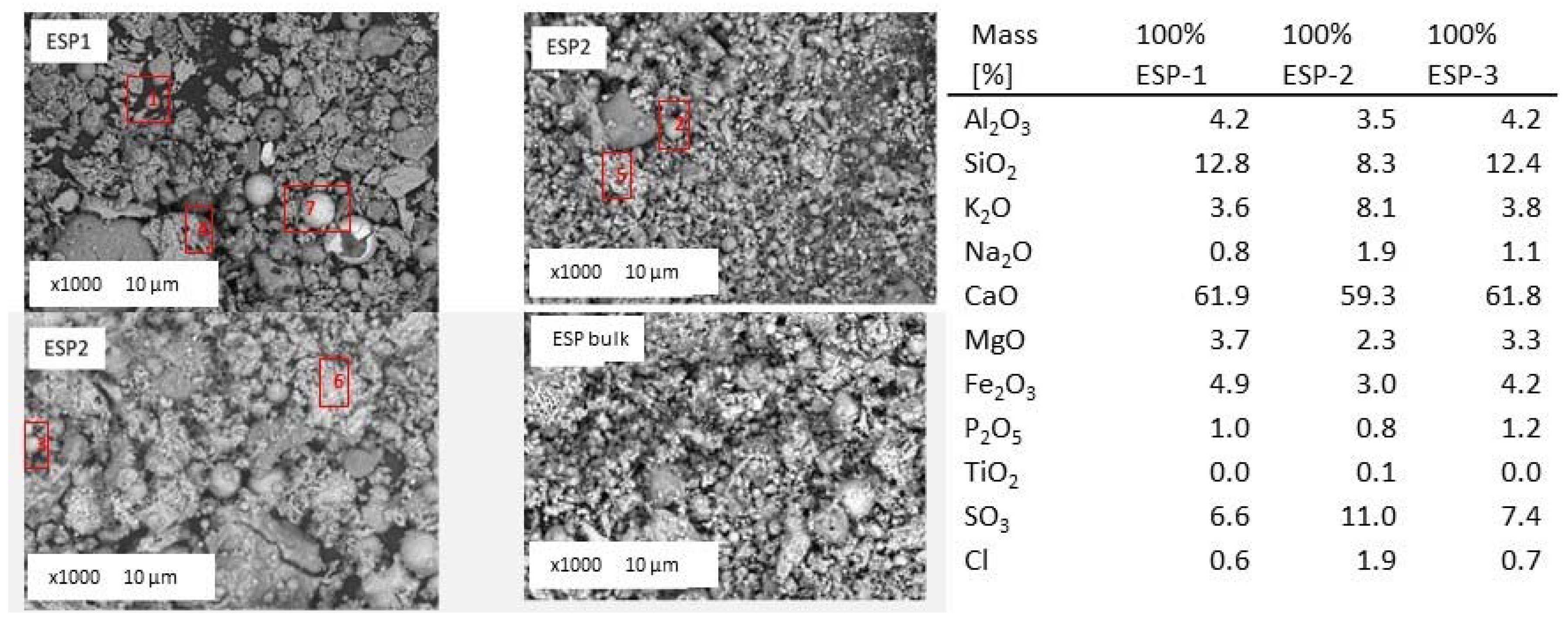
In the figures in this section, ESP hopper samples are numbered from 1 to 3, and a sample is identified as the bulk ash. The first three fly ash samples correspond to the three batches of ash precipitated at the three hoppers in the ESP (ranked from the coarser fraction, number 1, to fine the fraction, number 3). The bulk sample is a mixed representative fly ash of the ESP for each firing scenario. Figure 14 shows the general overview of collected fly ash samples during pure lignite combustion tests. The chemical composition of the fly ash from the three hoppers collected during pure lignite combustion from energy dispersive X-ray (EDX) analyses is given in the figure too. The EDX analyses are normalized on carbon and oxygen free basis, expressed in oxides.
An amorphous particle, number 1, represents an alumina-silicate compound enriched in iron and some potassium along with smaller amounts of calcium and magnesium. Particle number 2 is an example of a particle when calcium was primarily associated with oxygen and some sulfur.
The median particle size varied between 6 and 80 μm, with the larger particle sizes generally corresponding to fused molten agglomerates, see particle numbered 3. There is no significant difference in morphology of the particles collected at various hoppers, apart from the particle size. Obviously ash particles in the sample number 3 (from the third hopper) are smaller (see magnification). From the bulk sample, both mineral (particle number 4) and amorphous components (particle number 5) can be identified. Spherically and colorless particles indicate glassy textures or predominance of crystallinity and spherical, rounded light colored particles indicate a glassy surface [65]. Rounded particles indicate a glassy particle, irregular shapes indicate partly crystalline particles, and angular shapes indicate a crystalline nature [65,66]. As determined by EDX, the predominant elements in the fly ash samples were calcium, silicon, aluminum, iron, magnesium and sulfur in various compounds. Calcium was observed to primarily be associated with oxygen, sulfur, and silica, or possibly with carbon (calcite). Particle number 6 shows a particle with holes, which represent such particles in the fly ash. Volatiles trapped in a particle cause it to have swelled surfaces, varying the shape of the particles and bubbles, which alters its surface [67]. The bubbles formed may be attributed to the release of volatile matter from the internal zones of the particle as the solid particle’s surface is softening and melting [67]. The bubbles can generate large cavities under the surface, which are smooth zones and considered to be less reactive for the subsequent steps of oxidation [67]. This indicates a continuing combustion, which may have undesirable effects on the fly ash quality due to the presence of such apparent uncomplete combusted particles. Such particles were qualitatively observed to be more prevalent in the fly ash from the lignite scenario. This suggests the lignite case had the least optimal combustion performance.
Figure 15 shows the general overview of collected fly ash samples during 10% thermal share co-firing of Cynara. The chemical composition of the fly ash from the three hoppers collected during 10% thermal share co-firing of Cynara from EDX analyses is given in the figure too. There is no significant difference in morphology of the particles collected at various hoppers.
The coarser fraction (20–90 μm), in ESP1, is mainly composed of alumina silicates particles with potassium, calcium rich crystalline phase, and iron and magnesium oxides The SEM-EDX data showed calcium is associated with sulfur or oxygen in distinct particles, (see Figure 15, particle number 2). Sulfur captured by lime, which is originating from fuel, is widely known as a self-desulfurization process. This process leads to a spontaneous reduction of SO2 emissions in industrial boilers. The observation support the assertion noted in Section 3.4.3, regarding the enrichment of elements in the fly ashes.
Particle 1 is an example of an amorphous alumina-silicate sphere. The majority of the iron-rich spheres observed consisted of an iron oxide mixed with amorphous alumina-silicate. Compared to the previous fly ash sample (100% lignite combustion), the fly ash samples from 10% thermal share of Cynara co-firing contain less calcium, but more aluminum, silica, iron, and sulfur. Char particles with holes were detected in this fly ash too, see particle number 3 and particle number 4. Those particles indicate a swelling phenomenon and structural changes after devolatilization that led to melting and fusion into a mass with smooth surfaces. A particle with irregular and indented surfaces expose more active sites for gaseous reactant than a smooth surface, which influences the reactivity of the char [67]. Thus, those char particles were not as reactive, which apparently led to their presence in the fly ash.
Necked and interlocked particles appear to be more prevalent in the 10% Cynara bulk ash compared to the lignite scenario, which generally increased in the bulk ash with the increase in the co-firing share of Cynara. The agglomeration phenomena may be the result of low melting compounds, mainly, alkali in biomass ashes, than can stick contacting surfaces of separate particles, causing them to cluster [67]. Moreover, for this fly ash, the increase in irregular, elongated, flat, etc. particles may be associated with more particles considered as fissures. Fissures, holes, and superficial porosity represent the way volatile gases escape and for gaseous reactants to reach the active sites inside the char particle for oxidation [67]. Fissures, which are associated with a scabrous particle surface with a wide distribution, lead to a more reactive particle [67]. Thus, the apparent qualitative increase of irregular particles in this ash compared to the lignite scenario may suggest a better burning behavior of the fuel blend.
The general overview of collected fly ash samples during 50% thermal share co-firing of Cynara is shown in Figure 16. Mineral (particle numbers 1 and 2) and amorphous (particle numbers 3 and 4) components can be identified. The chemical composition of the fly ash from the three hoppers collected during 50% thermal share co-firing of Cynara from EDX analyses is given in the figure too. There is no significant difference in the morphology or in the particle sizes between various hopper ashes.
The median particle size varied between 1 and 30 μm that means somewhat smaller sizes than in the lignite and 10% thermal share fly ashes, which is different than the particle size distribution of the bulk ash shown in Section 3.3. The predominant elements in the fly ash samples were calcium, silicon, aluminum, iron, magnesium, sulfur and potassium in various compounds. Aluminum was observed with silicon and potassium. Apart from alumina-silicates, silica has been identified as a quartz too. Calcium was primarily associated with oxygen, sulfur, and phosphate. Again, this observation supports the assertion of the ash formation process in Section 3.4.3 from the addition of natural gas.
For this fly ash quality, there was an apparent increase in irregular, fused, etc. particles. This may be attributed to more biomass particles in the fuel blend, giving rise to a higher temperature. At higher heating rates, from a higher temperature, particles can partially or completely melt, losing their distinction, fusing together, and forming completely or partially hollow particles and smoothed surface particles too [68]. Also, a higher temperature implies not only a higher heating rate but also a rapid evolution of gases that build up pressure during volatile release, which may change the shape of some parts of the particle structure and cause some particle breaking (fragmentation) [69]. The increase in pyrolysis pressure has the potential to lead to the formation of larger particles due to swelling as well as formation of particle clusters as a result of melting and subsequent fusion of particles [68]. This is likely the mechanism of the clusters of particles formed with an increasing share of Cynara in the fuel blend. This may support a better overall burning of the chars for co-firing cases, as the 50% thermal share of Cynara had a lower LOI than the 10% thermal share of Cynara.
Figure 17 shows fly ash samples from the ESP hoppers and the mixed bulk fly ash collected during the 100% thermal share Cynara tests. The chemical composition of the fly ash from the three hoppers collected during the 100% thermal share Cynara tests is given in the Figure too from EDX analyses.
The fly ash contains amorphous (point numbers 1, 2 and 3) and crystalline ash particles of various shapes. The median particle size varied between 4 μm and 80 μm, with the larger particle sizes (particles numbers 4, 5 and 6,) generally corresponding to fused molten agglomerates. The sphere-shaped ash particles are composed mainly of aluminum and silicon, with potassium and calcium. The detection of alumina-silicate with potassium, as it was not detected in the other fly ash samples, could be attributed to the lower calcium content in the biomass fuel. Calcium is also the main ash forming element in the 100% Cynara fly ash samples. Next to alumina-silicate cenospheres, similar particles, but then enriched in iron (ferrospheres) (particle number 7) were identified. Next to particle number 7, it can be seen a hollow ferrosphere as a result of the possible expansion of trapped volatile matter. Ferrospheres may be associated with heavy metals, such as Cu, Cr, Pb, and Zn due to inorganic, organic, and intermediate affinity of trace elements, which may make environmental pollution risks a paramount importance [70]. The identification of ferrospheres give rise to a multi-utilization of the fly ash as they can be economically extracted by magnetic separation techniques that have industrial possibilities in metallurgy, ore and coal dressing processes, and dense concrete production [70]. The iron oxide exhibits various textures even the dendritic pattern was found. The fine fraction of the ash deposit from the 100% Cynara scenario is mainly associated with calcium, but also with potassium and sodium oxides, sulfates, phosphates and chlorides. Several crystalline particles containing alkali metals and sulfur with chlorine were identified. Since alkali chlorides crystal structure is octahedral as calcium oxide, it is difficult to clearly distinguish between various compounds. Nevertheless, the fly ash samples contain significantly higher amount of sulfur, potassium, and chloride compared to the other fly ashes. Compared to the 50% Cynara co-firing scenario, there is more potassium, sodium, and chloride in the fly ash from 100% Cynara combustion. The concentration of the sulfur remains comparable. Without the interaction of the lignite ash, i.e., more alumina-silicates and calcium available, the volatile species were more readily able to react with compounds of sulfur, silica, etc. that contributed to their capture in the fly ash. This is supported by the enrichment of elements for the 100% Cynara combustion test scenario shown in Section 3.4.3.
It is noted that for the influence of aggregates on concrete (an engineering construction material) shrinkage, flaky, elongated, angular, and rough aggregate particles have high voids, requiring more material to fill them, which increases water demand and shrinkage [71]. Spherical and cubical aggregates with their less specific surface area than flat and elongated particles require less water for use, and they lead to lower shrinkage than flaky and elongated aggregates [71]. The irregular particles can be overcome by applying a grinding fly ash post-treatment process to reduce the particles that are fused and create more spherical particles [72]. Thus, the inclusion of Cynara in the fuel blend may necessitate a small grinding post-treatment process to obtain an optimal fly ash for use in construction engineering materials, i.e., concrete and mortar for various masonry applications.
From the SEM analyses, it is seen that the fly ash samples consist of particles of various shapes and sizes. At temperatures in a pulverized fuel boiler, generally in excess of 1400 °C, the mineral matter within the fuel oxidizes, decompose, fuse, undergo fragmentation, agglomerate, etc. During the burning of coal, rapid cooling in the post-combustion zone results in the formation of spherical, amorphous (non-crystalline) particles, (≤90%), or glass and a small amount of crystalline material [3]. Shown in Section 3.4, the average chemical composition was relatively consistent for the pure lignite, 10% Cynara thermal share, and the 50% Cynara thermal share. The major element in all fly ash samples is calcium. The relatively bigger molten agglomerates are composed mainly of alumina silicates with large proportions of potassium. The coarse fly ash fraction may also contain significant amounts of calcium sulfates. Next to the coarse fraction, agglomerates of very fine particles (<<1 μm) clustered together were observed too. The fine fly ash fraction (ESP3) is formed from volatilized ash material that condenses in the cooling flue gas. The 100% Cynara combustion test resulted in alkali salts formation in submicron particulates. Moreover, with the increasing share of Cynara in the fuel blend, there was a reduction of amorphous particles (mainly associated with spherical particles) and an increase in irregular particles. Thus, the effects of irregular particles with more inner voids may need to be considered when deciding the utilization route of fly ash produced from Cynara in the fuel blend, which will be dependent upon the application.

3.6. X-ray Powder Diffraction Analyses of the Ashes

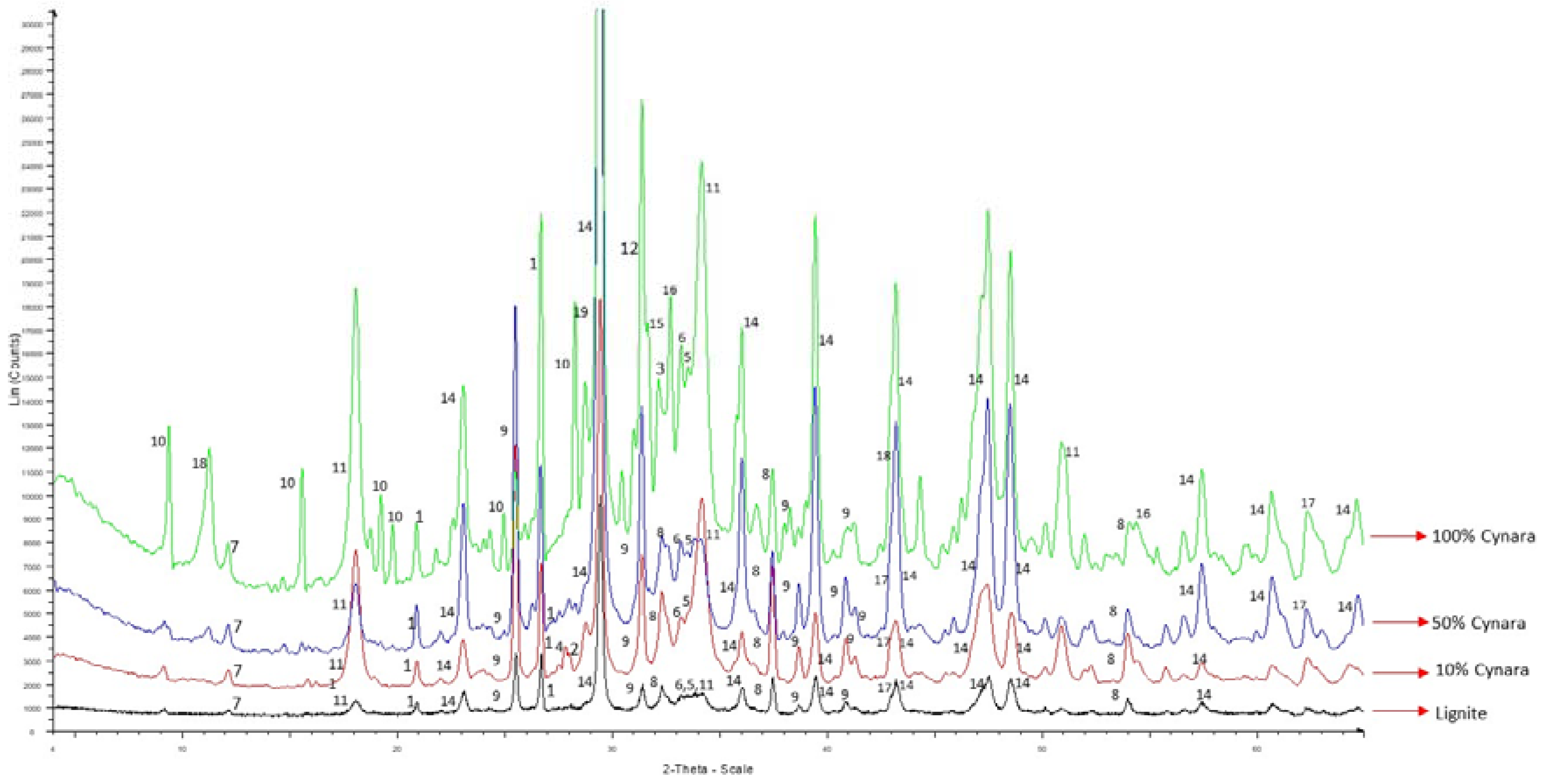
Most elements in fly ash occur in both organic and inorganic matter, and each has a dominant association and affinity with some mineral phases [73]. Elements in fly ash can occur in distinct phases that occur in different content, size, morphology, association, and generation in fly ashes, namely active, semi-active, pozzolanic, or inert mineral phases [73]. Each crystal phase group has individual behaviors regarding hydration-dehydration and hydroxylation-dehydroxylation processes in fly ashes, which have a leading role in the production of construction materials that is missing information from the bulk chemical composition of fly ashes [73]. Characterizing, identifying, and quantifying the phase mineral composition, along with the chemical content, of biomass ashes, are initial and necessary steps for assessing their utilization [57]. Minerals are also essential for the building industry, where fly ash is likely to have a significant use, with lime and siliceous acid being among the most important for this industry [74]. The elements will form different minerals in co-fired biomass ash compared to coal ash or lignite ash. X-ray powder diffraction scans of the fly ashes from the different scenarios were compared among each other, as shown in Figure 18. Table 7 shows the minerals detected in the fly ashes for all scenarios.
Table 7 shows that fly ash qualities are dominated by calcium minerals, as expected. Dominated by calcium minerals are lignite fly ashes [75]. The mineral phases in fly ashes are categorized as noted below, with calcium based minerals having active qualities and the most desirable in fly ashes for masonry uses. The following list highlight those categories [57]:
  • Active (lime, periclase, anhydrite, bassanite, Ca and Ca-Mg silicates and alumina-silicates, ca-enriched glass, among others);
  • Semi-active (portlandite, brucite, gypsum, carbonates, clay and mica minerals, feldspars, Fe oxides, Ca-containing glass, among others),
  • Pozzolanic (glass); and
  • Inert or inactive (quartz, mullite, some char) behavior during hydration-dehydration and hydroxylation-dehydroxylation processes of biomass ashes.
The XRD analyses showed that there were no alkali-sulfates detected in the fly ashes from the co-firing trials. The K in a sulfur phase detected in the 100% Cynara combustion is in agreement with SEM-EDX observations. Thus, it is maintained that the inclusion of natural gas in the co-firing fuel blend led to more sulfur being transformed to the more reactive SO3 species, as explained in Section 3.4.3. The effect reduced the available sulfur to form alkali sulfates. This may be a major reason why the lignite ash and the co-fired ashes are more similar than anticipated. Therefore, an optimal co-firing of a low-quality lignite and an herbaceous biomass fuel may be with natural gas in order to mitigate ash related problems. More work is needed in this area.
It’s necessary to classify fly ashes according to their potential pozzolanic activity and cementitious properties, as well as others if needed, such as alkali-aggregate reactivity and sulfate resistance [53]. Fly ash produced from combustion of low-rank lignites and sub-bituminous coals have both cementitious (self-hardening when reacted with water) and pozzolanic properties [73]. The pozzolanic mineral phases undergo pozzolanic reactions, which are mainly diffusion controlled and begin at a much later period in the hardening system [57]. Fly ashes with medium to little pozzolanic tendencies and generated from fuels with a variable rank, but mostly lignite, to a lesser extent bituminous coals and rarely anthracites, are active types [73]. The primary key to the pozzolanic reaction is the structure of the silica, which must be in a glassy or amorphous phase with a disordered structure, being formed, like in the rapid cooling of a volcanic magma [28]. If the silica is in a uniform crystalline structure, like found in silica sand, it is noted to not be chemically active [28]. The fly ash qualities produced in this work are considered to have both cementitious and pozzolanic qualities as it is expected to be some amount of amorphous matter in fly ash produced in pulverized fuel boilers, as quenching retains high temperature phases and melts will appear as glass [76], but below about 5%, it may not be detected by XRD analyses.
Primary minerals present do not undergo transformations during combustion, such as stable silicates [73]. Quartz, which is a primary mineral and can be essentially non-reactive in combustion processes due to its high fusion temperature [77]. Also, the quartz mineral, which may form by partial crystallization of the glassy phases in fly ash, decrease expansion from of alkali-aggregate (i.e., silica in the aggregates) reactions in concrete, and they are non-reactive [49]. Quartz was found in all ash samples but had a qualitative decrease with increasing co-firing shares, which was an observance from peak intensities.
Anhydrite (CaSO4), forming from the reaction of CaO, SO2 and O2 in the furnace or flue, plays a role in concrete’s hydration behavior [75]. Shown below are the reactions of forming anhydrite (Equations (8) and (9)) [78]:
CaO(s) + SO2(g) +1/2O2(g) → CaSO4(s)
CaO(s) + SO3(g) → CaSO4(s)
Anhydrite may also be formed from the dehydration of gypsum [1,77], dehydration of bassanite (CaSO4·1/2H2O), or between a sulfuric acid (generated during sulfide oxidation) and calcium carbonates in the coal/lignite. Shown below is the reaction (Equation (10)) of gypsum decomposition [1].
CaSO4·2H2O → CaSO4(s) + 2H2O(g)
Anhydrite along with other soluble aluminates lead to the formation of ettringite (trisulfate of calcium aluminate) immediately upon addition of water to fly ash; the initial hydration reaction contributes much to the self-hardening characteristics of fly ash, which can participate and control the solubility of potentially hazardous trace elements [75]. The decrease of quartz and increase of anhydrite, found in all samples, with the increasing co-firing share, implies an increased reactive fly ash quality. The lime decreased in fly ash with co-firing of Cynara, which is a result of the lower level in the biomass. It is likely formed via the reaction of calcium in the fuel with oxygen, see below (Equation (11)) [79]:
Ca(s) + 1/2O2(g) → CaO(s)
The lime may also be formed by the mechanism of the breakdown of calcium carbonate in the fuel. The strongly endothermic process leads to the breaking up of the chemical bond in the carbonate ion and the rearrangement of ions to form CaO crystals and the diffusion of CO2 out of the cluster of lime crystals, as shown below (Equation (12)) [25,80]:
CaCO3(s) + O2(g) + heat energy → CaO(s) + CO2(g)
The lime may also be formed from calcium incorporated into the organic matter [77]. The decreae in calcium oxide implies a decrease in any free lime (CaO) potential. Free CaO in excess amounts must be limited or unsoundness (undesirable volume change [25]), i.e., expansion, could occur during hydration processes in concrete [81]. Furthermore, free CaO in ash may react with water forming Ca(OH)2, causing an increased volume and structural destruction of concrete [82]. Probably formed via the reaction shown below (Equation (13)) was the portlandite mineral [83]. The mineral’s presence in the fly ash increased with the 10% Cynara co-firing, but decreased with the 50% share:
CaO(s) + H2O(g) → Ca(OH)2(s)
Formed via the reaction of CaO with CO2 is calcite as shown below (Equation (14)) [25,84]. The reaction is widely known:
CaO(s) + CO2(g) → CaCO3(s)
The periclase mineral may be formed via the general reaction shown below (Equation (15)) for the decomposition of carbonates in the fuel [38]:
MCO3MO + CO2
where M equals Fe, Mg or Mn. The periclase may also be formed form the reaction indicated below (Equation (16)) [85]:
Mg(s) + 1/2O2(g) → MgO(s)
Also, the periclase may be formed from incorporation into the organic matrix [77]. The increasing co-firing shares led to a reduction of periclase, and it was not detected in fly ash from 100% Cynara combustion. Deduced is the association of the mineral with the lignite fuel, and its absence in higher co-firing Cynara shares suggests an improved fly ash quality. Free MgO present above a certain size [34] slowly hydrates yielding brucite (Mg(OH)2), causing vast and localized volume increases, leading to deleterious expansion [34,75].
The primary agents for hardened concrete’s expansion and cracking from sulfate attack are alumina-bearing hydrates (like calcium monosulfo-aluminate and calcium aluminate hydrate) [32]. Those hydrates are attacked by the sulfate ion forming ettringite or calcium tri-sulfoaluminate [32], a high sulfate form [86], or by forming gypsum or wollastonite [42]. The gypsum formed reacts with calcium aluminate hydrates (4CaO·Al2O3·19H2O) and calcium alumino-sulfate hydrates (3CaO·CaSO4·18H2O), producing the insoluble ettringite that can lead to expansion (from reactions causing expandable pressure) causing deterioration of already hardened concrete due to high tensile stresses, according to the reactions that follow (Equations (17) and (18)) [42]:
4CaO·Al2O3·19H2O + 3CaSO4 + 14H2O → 3CaO·Al2O3·3CaSO4·32H2O + Ca(OH)2
3CaO·CaSO4·18H2O + 2CaSO4 + 14H2O → 3CaO·Al2O3·3CaSO4·32H2O
Thus, the co-firing of Cynara with natural gas is believed to reduce the risks associated with calcium aluminates in the fly ash, as there were no detection of alkali sulfates, despite the extremely high amount of alkalis in the biomass fuels. Anhydrite also participates in the problematic reaction for concrete, but in masonry applications, anhydrite is an important mineral, e.g., for render, mortars, or binders on building sites [74], as adhesion and binding properties have a precedence.
For the 50% thermal share of Cynara co-firing, it was observed that mineral phases were similar to the 10% thermal share of fly ash. This is considered to be a significant finding due to the much higher content of problematic ash species in the biomass fuel. However, the merwinite and andradite phases had a relative decrease from peak intensities in the 50% Cynara co-firing fly ash. Both of those phases are calcium bearing and would have contributions to the reactivity of the fly ash. A relative decrease with a relative increase in calcite may not change the fly ash reactive nature to any significant extent. Merwinite is formed by the reaction below, (Equation (19)) [1]:
3CaO(s) + MgO(s) + 2SiO2(s) → Ca3Mg(SiO4)2(s)
Lime had a somewhat lower peak intensity in the 50% Cynara co-firing case compared to the other scenarios. The observation may be due to interactions of the fuels leading to reduced reaction rates for this thermal share impacting conversion of species or attributed to the increase and formation of other minerals involving Ca and Si. Further work is needed to clarify the observation.
Dolomite and sylvite were detected in the pure biomass combustion fly ash. The presence of dolomite in the fly ash from the pure combustion of Cynara is a testament to the fuel’s larger particle sizes that require a longer residence time to burnout than design of the boiler for coal particles. Dolomite is formed by the reaction below (Equation (20)) [87]:
CaCO3(s) + MgO(s) + CO2(g) → CaMg(CO3)2(s)
The presence of sylvite in the pure Cynara combustion is due to the high amount of the species in the biomass and their subsequent reaction in the furnace and condensation in cooler regions. Also, the presence of KCl is attributed to the reduction of ash amount in the fuel blend containing silicates to form compounds with K. Sylvite is formed by the reaction sequences below (Equations (21) and (22)) [21,88]:
HCl(g) + KOH(g) → KCl(g) + H2O(g)
KCl(g) → KCl(s) (condensation of aerosols)
Ash composition changes during storage and under varying environmental conditions as carbon dioxide and moisture react with ash to form carbonates, bicarbonates, and hydroxides [89]. Absorption of water on a molecular level is noted to be possibly due to the hydrophilic nature of ash and to small charge imbalances [89]. Thus, the hydroxide mineral phases for the 100% Cynara are attributed to the ash being hydrophilic.
The co-fired fly ash qualities generated may be useful were setting times are of concern, as the self-hardening properties can improve the setting time. Suitable applications may be pavements, parking lots, road embankments, and other trafficked areas due to self-hardening characteristics that improve the setting time [54], bonding, and possibly adhesion qualities, characteristics associated with calcium minerals [74]. The fly ashes appear to have a high value in masonry applications, such as making bricks, etc. Overall, co-firing a herbaceous biomass up to 50% thermal share with a low-quality lignite that has a high ash content and with natural gas in the fuel blend positively influence the fly ash quality.

3.7. Behavior Characteristics from Performance Test Applications of Some Fly Ashes

The technically quality of how a fly ash performs in a given application is generally good if the performance is equal to or better than the commercial available material for the same application [16]. A key aspect in accepting the use of an industrial mineral like fly ash is its technical suitability and the ability of a power plant to supply a constant-quality product, which is guaranteed by specifications and certifications [16]. Thus, the co-fired ash performance in certain applications was compared to the lignite ash.
Soundness testing gives an evaluation of possible impacts on durability in concrete from using the fly ash quality. This assessment of volume expansion (instability) is necessary when assessing long-term performance considerations of using the fly ash, for example, in concrete. Table 8 shows results of soundness testing of ashes from co-firing 10% and 50% thermal shares of Cynara compared to the lignite only case.
All fly ash samples tested met the limit for expansion. Shown is the addition of Cynara does not have a negative impact on the long-term stability characteristic compared to the lignite fly ash, and the 50% thermal share even improve the performance compared to the lignite. The apparent improvement shows that a 50% thermal share of co-firing Cynara with a low-quality lignite can improve the fly ash quality. Further long-term studies are needed.
Another technical parameter of importance is the initial setting time. The initial setting time is necessary for assessing when a concrete mixture can be expected to become rigid. The time of set of concrete mixes impacts a construction project schedule. Many factors influence the initial time of setting. Some factors are listed below [49]:
  • The fly ash may contain high calcium amounts (self-hardening);
  • Fly ash may contain sulfates that react with cement;
  • The mixture may contain less water due to the presence of fly ash, and this will influence the process of hardening;
  • The fly ash may impede surface-active agents added to modify the rheology (water reducers) of concrete, and again this impacts the stiffness of mortar; and
  • Fly ash particles may act as nuclei for crystallization of cement hydration products.
In Table 9 are shown initial setting times results of some tested fly ashes. A control sample is shown for enhancing comparisons. The impact of Cynara in the fuel blend is apparent.
Table 9 shows that co-firing Cynara improved the setting time performance of the fly ashes. The improvement is also expected with the 50% thermal share, although not tested due to the unavailable material. The improvement in setting time with Cynara addition could be a result of reduced compounds in the fly ash that do not have good self-hardening properties an enhanced burning of the fuel blend with the biomass that contribute to an increase in mineral phases with hydraulic properties, i.e., anorthite (CaAl2Si2O8) was shown in Table 7, or an improved reactivity of the fly ash from a finer particle size distribution, as was shown in Section 3.3.
Strength is the most important parameter used to characterize cement-based products; thus, the determination of compressive strength is the most important property of construction materials [90], mainly concrete as a structural material [27]. Compressive strength is widely used as an index of all other types of strength categories [91]. The experience with using fly ash in structural concrete has seen about 30% substitution of the binder, where the possibility is shown for a similar or improved performance in comparison to OPC concrete of equivalent 28-day strength [32]. The development of compressive strength on the fly ash generated from the lignite baseline case and the 10% thermal share of Cynara are evaluated in Figure 19 for a 10% cement substitution. Also, a comparison of the results to the same type of tests for fly ash from the industrial Kardia Power Plant was performed. Characterization of strength development occurred for 1, 2, 7 and 28 days.
Figure 19 shows that the 10% cement substitution of Cynara fly ash from a 10% thermal share produces a fly ash with nearly the same early strength development behavior and a similar 28-day strength development compared with the lignite fly ash. After grinding the fly ashes, the 28-day strength for the 10% thermal share of Cynara fly ash at a 10% cement substitution has nearly the same strength value as the pure lignite combustion fly ash. Also, after grinding, the 28-day strength for the 10% thermal share of Cynara at a 10% cement substitution has a 28-day strength development very close to the pilot-scale 10% thermal share Cynara fly ash at a 10% cement substitution.
Grinding of fly ashes is a way to reveal their pozzolanic and hydraulic properties [92]. Results indicate that a 10% thermal share of Cynara in the fuel blend for a low-quality lignite would have the same behavior as a cement substitution where a lignite only fly ash applies. Also, from the results, ash obtained from the pilot-scale tests are considered to be representative of industrial fly ash behaviors. Figure 20 shows strength development with substituting 20% of the cement with fly ash.
The 20% cement substitution in Figure 20 shows the same trend for strength development as the 10% cement replacement. Also, the values are very close, but with a noticeable slight increased variation. After grinding, the performance of the 10% thermal share fly ash at 20% cement substitution is the same as the lignite fly ash. Again, this shows the added value in a small co-firing proportion of a herbaceous biomass with a low-quality lignite on the fly ash quality. A higher cement substitution rate contributes more to mitigating CO2 emissions from the manufacture of cement. Figure 21 shows the comparison of strength development for 10% thermal share of Cynara fly ash from KSVA with industrial fly ashes with a 30% cement substitution.
The values for the 30% cement substitution are lower than the other values, as expected due to the presence of less cement in the mix for hydration to supply Ca(OH)2 needed to react with the pozzolanic fractions of the ash. So, it will take a longer time to start the reactions with fly ash, as the pH required is reached a later time compared to the other lower substitution rates. The industrial fly ash was not ground and compared, but the trend of exact values for the pilot-scale (KSVA) results should be the same, like the results for the other substitutions. An optimal replacement amount for utilization in concrete applications (with a technical approval) is likely at about 25% cement replacement, which is the practice according to EN 450-1 for bituminous coal ashes or ashes from co-firing particular green biomass fuel with bituminous coals. On the other hand, many masonry applications do not have the strict material provisions and conservative design like EN 450-1. Many masonry applications allow one to choose the components of a binder to meet specific performance requirements, e.g., EN 998-1, focusing on binding and adhesion properties. So, performance studies of the fly ash qualities in masonry applications could result in a significant higher amount of cement being replaced by the fly ash qualities. That would be a huge benefit as the total energy required based on kJ/kg of material is 372 and 0 for cement and fly ash, respectively [75].
From the results, a high thermal share of Cynara does not appear to change the fly ash quality for economic utilization applications, despite the significantly higher contents of problematic ash components. At 50% thermal share of Cynara, the amount is likely able to meet a good fuel sustainable supply, easy handling and storage capabilities, efficient milling and feeding capabilities, and a normal boiler operation and performance. Thus, it is believed that a co-firing 50% thermal share of Cynara can be employed based upon the overall presented results without having negative impacts on the fly ash quality. This would also stimulate local and regional economies and may be a catalyst to promote trade between countries for such a biomass type to co-fire with lignite fuels. Quality fly ash standards requiring a minimum of co-firing of an herbaceous biomass with a low-quality lignite fuel on a thermal share basis would have far reaching positive benefits across environmental sustainability practices in lignite fuel combustion and biomass ash management. Such legislation can be employed regionally, nationally, EU-wide, or even internationally through European and ISO standards. However, such a practice needs assessment on a case basis for herbaceous biomass fuel types, since logistics and fuel supply would take priority, along with boiler performance concerns.
The largest use of ashes in Greece is in the cement industry to replace cement clinker and production of special cements, which include successful tests in road construction, mortars, waste treatment, embankments, and cement grouting [92]. From results, it is believed a co-firing share of up to 50% of Cynara biomass does not change those utilization options when potentially substituted up to 30% by mass of the cement content. Further long-term studies are needed.
From the technical performance test results, it is believed that co-firing of the Cynara biomass with a low-quality lignite would be added value to a lignite power plant not operating at boiler load swings, which would be enhanced at a boiler de-rate with the inclusion of natural gas into the co-firing fuel mix. However, at lower loads there may be an impact on fuel/gas mixing due to changes in velocity and momentum [60,93]. Changes in running conditions of boilers result in variations of fly ash quality, as adjustments to the loading of boilers regularly have to take place to meet the changing demand for electricity, and the coexistence of alternative electricity generating options give rise to the policy of rapidly changing between supply sources for an optimal economy [16]. Co-firing of Cynara with a low-quality lignite in a boiler subjected to fluctuating operational conditions can possibly lead to keeping the variation of inhomogeneous fly ash to an acceptable condition, as the co-fired fly ashes had an equally comparable or better technical performance than the compared commercial material or baseline fly ash quality. This may be enhanced with the addition of natural gas into the fuel blend due to higher temperatures reached and a potential reduction of LOI values in the fly ash.
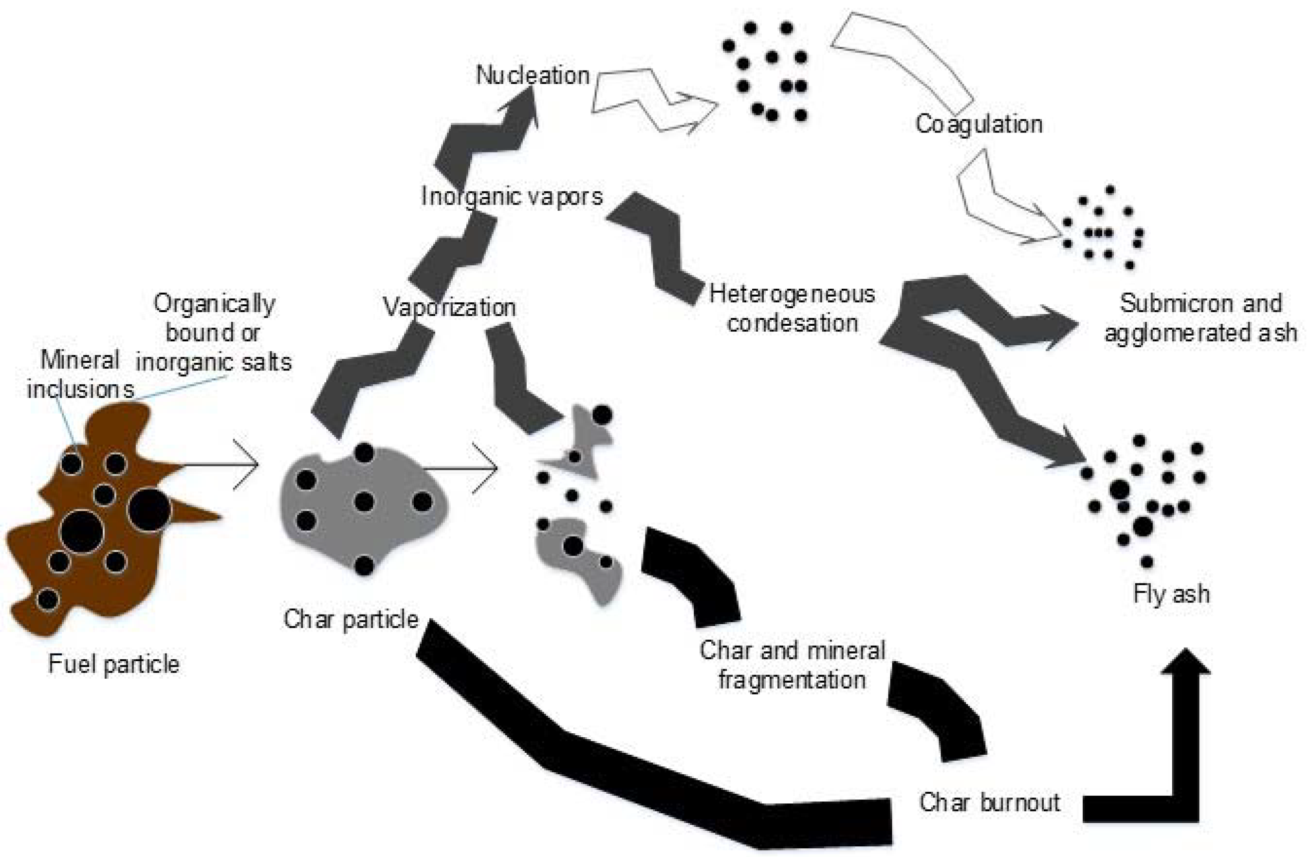
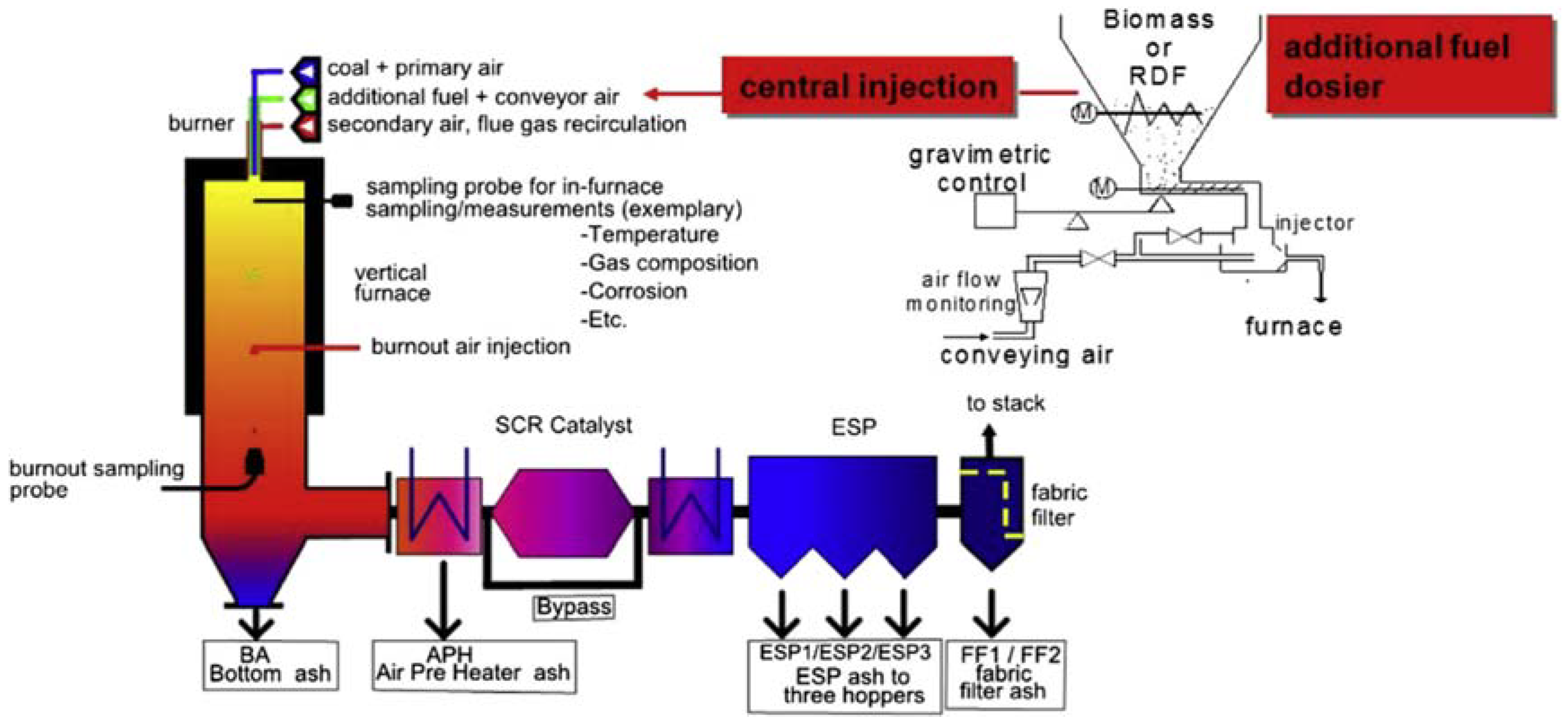
4. Conclusions

Pilot-scale test experiments of co-firing a low-quality Greek lignite and an herbaceous biomass along with the mono-combustion of each fuel were conducted to evaluate the effect of co-firing on the fly ash quality (ash formation, changes, and characteristics). Also, natural gas was used in the tests due to the low-quality of the lignite. Co-firing thermal shares were 10%, 50%, and pure biomass combustion. Results were compared to the same fuel qualities for industrial tests of lignite and 10% thermal share of Cynara.
Co-firing of a low-quality lignite with Cynara and natural gas in the fuel blend is believed to lead to a better conversion of SO2 to the more reactive SO3 in the furnace, resulting in more fuel self-desulfurization in the furnace with earth alkaline metals. This causes less alkali sulfates to be formed in the convection pass, which releases alkalis via the stack in the gas phase. Thus, more of the problematic ash components, i.e., alkalis and phosphates, are not significantly captured in the fly ashes due to a lower availability of sulfur. This potentially improves the quality of the fly ash for utilization in low technical applications and as a binder, as CaSO4 is a widely known self-hardening compound in building materials, especially in masonry applications. Thus, it appears that using natural gas in the co-fired fuel blend enhances the fly ash quality for uses not subjected to stringent material provisions, as the two fuels used during tests, generally, are considered problematic within their respective fuel categories.
With Cynara in the fuel blend, the fly ash qualities showed performance improvements over the lignite only fly ash when tested for initial setting times and volume stability. Those improvements were obtained without the need to grind the fly ash to break up the irregular, fused, angular, etc. particles. Thus, the co-firing of Cynara led to positive changes in the fly ash quality; however, further process analyses and techno-economic studies are necessary before Cynara can be considered as a sustainable co-firing component with lignite. Also, the reduction of periclase with an increasing Cynara share indicate an improved ash quality for application in constructions, as the mineral participates in unwanted reactions causing a destruction of hardened concrete. This is further added value in co-firing Cynara with a low-quality lignite. Furthermore, the particle size distribution of the fly ash with Cynara in the fuel blend was very similar to or better than the lignite fly ash, which is attributed to the higher heating value of the biomass and lower ash and water contents that can lead to a better ignition and combustion of the fuel. There would also be an enhanced particle fragmentation, which could be supported by the higher contents of alkalis in the Cynara that can improve heat transfer during combustion via more melt phases.
Scalability evaluations showed that the pilot-scale fly ashes are reliable to qualities produced in industrial facilities, from both particle size distribution and concrete specimens’ mechanical strength testing. Indirectly correlated to many other parameters of hardened concrete is the compressive strength and mineral phases have a significant influence on the occurrence due to their different reactivity and hydration properties. The similarities of compressive strength development in the fly ashes from the pilot-scale and industrial-scale testing indicate the reliability of pilot-scale results for observing interactions between the fuels, leading to various fly ash qualities.
In regards to reproducibility, the scalability observations show the potential of all the pilot-scale results to be reproduced with fly ash obtained at an industrial scale pulverized fuel facility. This suggests that the results can be reproduced with similar fuel qualities and the same thermal shares in a large-scale pulverized fuel facility with fly ash collected by an ESP. Moreover, all the methods and protocols followed are noted to facilitate the reproducibility of the results.
The co-firing results reported indicate that there is potentially no negative impact for uses that primarily access environmental concerns, regarding the possible use of the ashes for soil amelioration. This is based upon a likely sustainable co-firing share of up to 50% from fuel supply sustainability and operational capabilities. There may be an improvement in the ash quality for soil stabilization due to the increased calcium minerals, increased carbon in the ash, and an increase of mobility of nutrient species.
The co-firing of Cynara with a low-quality lignite would not only lead to a real benefits in the fly ash qualities but also contribute to reduced emissions of unwanted gasses species, such as CO2 and NOx, and sustainable energy production. The paper demonstrates that there is potentially no negative effect on ash quality up to 50% thermal share of Cynara co-fired with a low-quality lignite, and the observed improvement of the fly ash quality supports the assertion from literature that co-firing is a potentially attractive option to obtain a better fly ash quality in lignite boilers. This work validates the importance of co-firing Cynara or another herbaceous biomass with a low quality lignite, which may also have a positive contribution to local socio-economic developments. The results support efforts of biomass co-combustion in not only conventional air-firing, but also in lignite power plants that may be subjected to dispatch load requirements to support other renewable energy intermittent sources, e.g., wind and solar. as well as future oxy-fuel power plants, as long as sulfur concentrations are acceptable in the flue gas (risk of corrosion), contributing to measures to enhance operational flexibility and economic competitiveness. Moreover, the results could be very useful in future energy engineering projects that target not only the operational flexibility but also widening the fuel flexibility in flexibly operated lignite power plants.

Author Contributions

All authors contributed to the work presented in this paper. The writing of the original draft preparation was done by A.F. All authors were involved in preparing the final manuscript. All authors have read and approved the manuscript.

Funding

This research was funded by the European Seventh Framework Program (FP7/2007-2013) under grant agreement number 218968. The authors acknowledge the Demonstration of Large Scale Biomass Co-firing and Supply Chain Integration (DEBCO) project partners.

Acknowledgments

The authors acknowledge personnel at the Institute of Combustion and Power Plant Technology, the Materials Testing Institute (MPA Stuttgart, Otto-Graf-Institute (FMPA)), the Institute of Crystal Chemistry Faculty of Chemistry, all located at the University of Stuttgart, Germany, and the Laboratory of Inorganic and Analytical Chemistry, School of Chemical Engineers, National Technical University located in Athens, Greece for their collaboration and support.

Conflicts of Interest

The authors declare no conflict of interest.

Abbreviations

Symbol UnitValue
d μmparticle size
D10 μmthe diameter having 10% of the distribution as smaller particle sizes and 90% as larger particle sizes
D50 μmthe diameter having 50% of the distribution as smaller particle sizes and 50% as larger particle sizes
D90 μmthe diameter having 90% of the distribution as smaller particle sizes and 10% as larger particle sizes
fc MPa kJ/kgcharacteristic compressive strength
HLlower calorific value
L mmlength
M ˙ [kg/h]mass flow
ηair ratio
P [kWel]power
t minutestime
V ˙ [m3/h]volumetric flow
X %mass percent
γifuel mass fraction of the substance i (C, N, O, S, H, H2O, A (=ash))
ϑ [°C]temperature
ASTMAmerican Society of Testing and Materials
CENEuropean Committee for Standardization
ddry
dafdry-ash-free
DINDeutsches Institut für Normung e.V. (German Institute for Standardization)
ENEuropean Norms
ESPelectrostatic precipitator
FAfly ash
ISOInternational Standard Organization
KSVAKohlenstaubmahl- und Verbrennungsanlage (pilot-scale test facility)
RDFrefuse derived fuel
SCRselective catalytic reduction
SNCRselective non-catalytic reduction
TCtechnical committee

References

  1. Vamvuka, D.; Kakaras, E. Ash properties and environmental impact of various biomass and coal fuels and their blends. Fuel Process. Technol. 2011, 92, 570–581. [Google Scholar] [CrossRef]
  2. Massazza, F. Pozzolana and Pozzolanic Cements. In Lea’s Chemistry of Cement and Concrete, 4th ed.; Hewlett, P.C., Ed.; Arnold: London, UK, 1998; pp. 471–631. [Google Scholar]
  3. Xu, A. Fly Ash in Concrete. In Waste Materials Used in Concrete Manufacturing; Chandra, S., Ed.; Noyes Publications: Westwood, NJ, USA, 1997; pp. 142–183. [Google Scholar]
  4. Vassilev, S.V.; Baxter, D.; Andersen, L.K.; Vassileva, C.G. An overview of the chemical composition of biomass. Fuel 2010, 89, 913–933. [Google Scholar] [CrossRef] [Green Version]
  5. Cieplik, M.K.; Fryda, L.E.; van de Kamp, W.L.; Kiel, J.H.A. Ash Formation, Slagging and Fouling in Biomass Co-firing in Pulverised-fuel Boilers. In Solid Biofuels for Energy: A Lower Greenhouse Gas Alternative; Grammelis, P., Ed.; Springer: London, UK, 2010; pp. 197–217. [Google Scholar]
  6. Feuerborn, H.J.; Müller, B.; Walter, E. Use of Calcareous Fly Ash in Germany. Ash and Slaga Handling, 3.7 Analytics; EUROCOALASH 2012; Industrial By-Products Research and Development Association (EVIPAT): Thessaloniki, Greece, 2012. [Google Scholar]
  7. Zheng, Y.; Jensen, P.A.; Jensen, A.D.; Sander, B.; Junker, H. Ash transformation during co-firing coal and straw. Fuel 2007, 86, 1008–1020. [Google Scholar] [CrossRef]
  8. Wang, G.; Shen, L.; Sheng, C. Characterization of Biomass Ashes from Power Plants Firing Agricultural Residues. Energy Fuels 2012, 26, 102–111. [Google Scholar] [CrossRef]
  9. Sarabèr, A. Co-combustion and its impact on fly ash quality; pilot-scale experiments. Fuel Process. Technol. 2012, 104, 105–114. [Google Scholar] [CrossRef]
  10. Sua-iam, G.; Makul, N. Utilization of high volumes of unprocessed lignite-coal fly ash and rice husk ash in self-consolidating concrete. J. Clean. Prod. 2014, 78, 184–194. [Google Scholar] [CrossRef]
  11. Kisiela, A.M.; Czajka, K.M.; Moroń, W.; Rybak, W.; Andryjowicz, C. Unburned carbon from lignite fly ash as an adsorbent for SO2 removal. Energy 2016, 116, 1454–1463. [Google Scholar] [CrossRef]
  12. Masto, R.E.; Ansari, M.A.; George, J.; Selvi, V.A.; Ram, L.C. Co-application of biochar and lignite fly ash on soil nutrients and biological parameters at different crop growth stages of Zea mays. Ecol. Eng. 2013, 58, 314–322. [Google Scholar] [CrossRef]
  13. Kourti, I.; Cheeseman, C.R. Properties and microstructure of lightweight aggregate produced from lignite coal fly ash and recycled glass. Resour. Conserv. Recycl. 2010, 54, 769–775. [Google Scholar] [CrossRef] [Green Version]
  14. Moutsatsou, A.; Itskos, G.; Vounatsos, P.; Koukouzas, N.; Vasilatos, C. Microstructural characterization of PM-Al and PM-Al/Si composites reinforced with lignite fly ash. Mater. Sci. Eng. A 2010, 527, 4788–4795. [Google Scholar] [CrossRef]
  15. Pimraksa, K.; Hanjitsuwan, S.; Chindaprasirt, P. Synthesis of belite cement from lignite fly ash. Ceram. Int. 2009, 35, 2415–2425. [Google Scholar] [CrossRef]
  16. Cox, M.; Nugteren, H.; Janssen-Jurkovicova, M. (Eds.) Combustion Residues: Current, Novel and Renewable Applications; John Wiley: Chichester, UK, 2008. [Google Scholar]
  17. Llorente, M.F.; García, J.C. Suitability of thermo-chemical corrections for determining gross calorific value in biomass. Thermochim. Acta 2008, 468, 101–107. [Google Scholar] [CrossRef]
  18. Fava, G.; Naik, T.R. Compressive Strength and Leaching Behavior of Mortars with Biomass Ash. In By-Products Utilization Sustainable Construction Materials and Technologies: Conference Proceedings Downloads and Books; Claisse, P., Ganjian, E., Naik, T., Eds.; The University of Wisconsin Milwaukee: Milwaukee, WI, USA, 2016. [Google Scholar]
  19. Heinzel, T.; Lopez, C.; Maier, J.; Spliethoff, H.; Hein, K.R.G. Ash deposit and corrosion characteristics of coal-bioimass blends in a 0.5 MW pulverized fuel test facility. In International Conference: “Effects of Coal Quality on Power Plant Management: Ash Problems, Management and Solutions”; Mehta, A.K., Ed.; United Engineering Foundation: New York, NY, USA, 2001; pp. 2–27. [Google Scholar]
  20. Spliethoff, H. Power Generation from Solid Fuels; Springer: Heidelberg, Germany, 2010. [Google Scholar]
  21. Van Loo, S.; Koppejan, J. The Handbook of Biomass Combustion and Co-Firing; Earthscan: London, UK, 2010. [Google Scholar]
  22. Mineralogical Society (Great Britain). Microprobe Techniques in the Earth Sciences; The Mineralogical Society of Great Britain and Ireland: London, UK, 1995. [Google Scholar]
  23. Misra, M.K.; Ragland, K.W.; Baker, A.J. Wood ash composition as a function of furnace temperature. Biomass Bioenergy 1993, 4, 103–116. [Google Scholar] [CrossRef]
  24. Robinson, A.L.; Junker, H.; Baxter, L.L. Pilot-Scale Investigation of the Influence of Coal−Biomass Cofiring on Ash Deposition. Energy Fuels 2002, 16, 343–355. [Google Scholar] [CrossRef]
  25. Bye, G.C. Portland Cement: Composition Production and Properties, 1st ed.; Pergamon Press: Oxford, UK, 1983. [Google Scholar]
  26. Ramachandran, V.S.; Feldman, R.E. Concrete Science. In Concrete Admixtures Handbook: Properties, Science, and Technology, 2nd ed.; Ramachandran, V.S., Ed.; Noyes Publications: Park Ridge, NJ, USA, 1995; pp. 1–66. [Google Scholar]
  27. Abolpour, B.; Mehdi Afsahi, M.; Hosseini, S.G. Statistical analysis of the effective factors on the 28 days compressive strength and setting time of the concrete. J. Adv. Res. 2015, 6, 699–709. [Google Scholar] [CrossRef] [PubMed]
  28. Gehlen, C.; Eligehausen, R. Engineering Materials: Concrete: COMMAS-C7; University of Stuttgart: Stuttgart, Germany, 2006. [Google Scholar]
  29. University of Kentucky. Techniques for Measuring Ammonia in Fly Ash, Mortar, and Concrete; University of Kentucky Center for Applied Eneregy Research: Lexington, KY, USA, 2003. [Google Scholar]
  30. Vassilev, S.V.; Baxter, D.; Andersen, L.K.; Vassileva, C.G. An overview of the composition and application of biomass ash. Part 1. Phase–mineral and chemical composition and classification. Fuel 2013, 105, 40–76. [Google Scholar] [CrossRef]
  31. Knudsen, J.N.; Jensen, P.A.; Dam-Johansen, K. Transformation and Release to the Gas Phase of Cl, K, and S during Combustion of Annual Biomass. Energy Fuels 2004, 18, 1385–1399. [Google Scholar] [CrossRef]
  32. Ahmaruzzaman, M. A review on the utilization of fly ash. Prog. Energy Combust. Sci. 2010, 36, 327–363. [Google Scholar] [CrossRef]
  33. Yara. Yara Fertilizer Industry Handbook February 2012. Available online: http://www.yara.com/doc/37694_2012%20Fertilizer%20Industry%20Handbook%20wFP.pdf (accessed on 11 January 2013).
  34. Lawrence, C.D. The Constitution and specification of Portland Cements. In Lea’s Chemistry of Cement and Concrete, 4th ed.; Hewlett, P.C., Ed.; Arnold: London, UK, 1998; pp. 131–193. [Google Scholar]
  35. Lawrence, C.D. Physicochemical and Mechanical Properties of Portland Cements. In Lea’s Chemistry of Cement and Concrete, 4th ed.; Hewlett, P.C., Ed.; Arnold: London, UK, 1998; pp. 343–419. [Google Scholar]
  36. Odler, I. Hydration, Setting and Hardening of Portland Cement. In Lea’s Chemistry of Cement and Concrete, 4th ed.; Hewlett, P.C., Ed.; Arnold: London, UK, 1998; pp. 242–297. [Google Scholar]
  37. Ramachandran, V.S. (Ed.) Alkali-Aggregate Expansion and Corrosion Inhibiting Admixtures. In Concrete Admixtures Handbook: Properties, Science, and Technology, 2nd ed.; Noyes Publications: Park Ridge, NJ, USA, 1995; pp. 878–938. [Google Scholar]
  38. Gupta, R.; Wall, T.; Baxter, L. Impact of Mineral Impurities in Solid Fuel Combustion; Kluwer Academic: New York, NY, USA; London, UK, 1999. [Google Scholar]
  39. Karampinis, E.; Nikolopoulos, N.; Nikolopoulos, A.; Grammelis, P.; Kakaras, E. Numerical investigation Greek lignite/cardoon co-firing in a tangentially fired furnace. Appl. Energy 2012, 97, 514–524. [Google Scholar] [CrossRef]
  40. European Committee for Standardization. Specifications—Part 4: Fly Ash for Hydraulically Bound Mixtures; 93.080.20 (EN 14227-4:2013:E); CEN: Brussels, Belgium, 2013. [Google Scholar]
  41. European Committee for Standardization. Fly Ash for Concrete—Part 1: Definition, Specifications and Conformity Criteria, 5th ed.; 91.100.30(EN 450-1); CEN/TC 104; Technical Committee: Brussels, Belgium, 2012. [Google Scholar]
  42. Gu, X.; Jin, X.; Zhou, Y. Basic Principles of Concrete Structures; Springer: New York, NY, USA, 2015. [Google Scholar]
  43. Gu, X.; Jin, X.; Zhou, Y. Basic Principles of Concrete Structures, 1st ed.; Springer: Berlin/Heidelberg, Germany, 2016. [Google Scholar]
  44. Butler, W.B. Sulphate Attack on Concrete: What It Is and How to Stop It. Available online: http://www.adaa.asn.au/documents/Technical_Notes_2.pdf (accessed on 1 April 2013).
  45. Zacco, A.; Borgese, L.; Gianoncelli, A.; Struis, R.P.; Depero, L.E.; Bontempi, E. Review of fly ash inertisation treatments and recycling. Environ. Chem. Lett. 2014, 12, 153–175. [Google Scholar] [CrossRef]
  46. Pandey, V.C.; Singh, N. Impact of fly ash incorporation in soil systems. Agric. Ecosyst. Environ. 2010, 136, 16–27. [Google Scholar] [CrossRef]
  47. Jackson, P.J. Portland Cement: Classification and Manufacture. In Lea’s Chemistry of Cement and Concrete, 4th ed.; Hewlett, P.C., Ed.; Arnold: London, UK, 1998; pp. 25–94. [Google Scholar]
  48. Singer, J.G. Combustion: Fossil Power Systems a Reference Book on Fuel Burning and Steam Generation, 3rd ed.; Combustion Engineering: Windsor, CT, USA, 1981. [Google Scholar]
  49. Ramezanianpour, A.A. Cement Replacement Materials: Properties, Durability, Sustainability; Springer: Berlin, Germany, 2014. [Google Scholar]
  50. Backreedy, R.I.; Jones, J.M.; Pourkashanian, M.; Williams, A. Burn-out of pulverised coal and biomass chars. Fuel 2003, 82, 2097–2105. [Google Scholar] [CrossRef]
  51. Blissett, R.S.; Rowson, N.A. A review of the multi-component utilisation of coal fly ash. Fuel 2012, 97, 1–23. [Google Scholar] [CrossRef]
  52. Pedersen, K.; Jensen, A.; Skjothrasmussen, M.; Damjohansen, K. A review of the interference of carbon containing fly ash with air entrainment in concrete. Prog. Energy Combust. Sci. 2008, 34, 135–154. [Google Scholar] [CrossRef]
  53. Manz, O.E. Coal fly ash: A retrospective and future look. Fuel 1999, 78, 133–136. [Google Scholar] [CrossRef]
  54. American Coal Ash Association. Fly Ash Facts for Highway Engineers; National Technical Information Service: Springfield, VA, USA, 2003.
  55. Boycheva, S.; Zgureva, D.; Vassilev, V. Kinetic and thermodynamic studies on the thermal behaviour of fly ash from lignite coals. Fuel 2013, 108, 639–646. [Google Scholar] [CrossRef]
  56. Kalembkiewicz, J.; Chmielarz, U. Ashes from co-combustion of coal and biomass: New industrial wastes. Resour. Conserv. Recycl. 2012, 69, 109–121. [Google Scholar] [CrossRef]
  57. Vassilev, S.V.; Baxter, D.; Andersen, L.K.; Vassileva, C.G. An overview of the composition and application of biomass ash. Fuel 2013, 105, 19–39. [Google Scholar] [CrossRef]
  58. Ram, L.C.; Masto, R.E. An appraisal of the potential use of fly ash for reclaiming coal mine spoil. J. Environ. Manag. 2010, 91, 603–617. [Google Scholar] [CrossRef] [PubMed]
  59. Decagon Devices. Electrical Conductivity of Soil as a Predictor of Plant Response. Available online: http://old.decagon.com/assets/Uploads/Electrical-Conductivity-of-Soil-as-a-predictor-of-Plant-Response.pdf (accessed on 15 December 2014).
  60. Dusatko, G.; Brown, R. Gas Cofiring Assessment for Coal-Fired Utility Boilers: Technical Report; Final Report; Electric Power Research Institute (EPRI): Palo Alto, CA, USA, 2000. [Google Scholar]
  61. Bayless, D.J.; Schroeder, A.R.; Olsen, M.G.; Johnson, D.C.; Peters, J.E.; Krier, H.; Buckius, R.O. The effects of cofiring natural gas and coal on sulfur retention in ash. Combust. Flame 1996, 106, 231–240. [Google Scholar] [CrossRef]
  62. Muzio, L.J.; Often, G.R. Assessment of Dry Sorbent Emission Control Technologies Part I. Fundamental Processes. JAPCA 1987, 37, 642–654. [Google Scholar] [CrossRef] [Green Version]
  63. Jiménez, S.; Ballester, J. Influence of operating conditions and the role of sulfur in the formation of aerosols from biomass combustion. Combust. Flame 2005, 140, 346–358. [Google Scholar] [CrossRef]
  64. Zeuthen, J.H.; Jensen, P.A.; Jensen, J.P.; Livbjerg, H. Aerosol Formation during the Combustion of Straw with Addition of Sorbents. Energy Fuels 2007, 21, 699–709. [Google Scholar] [CrossRef]
  65. Watt, J.D.; Thorne, D.J. The composition and pozzolanic properties of pulverised fuel ashes: III. Pozzolanic Properties of Fly Ashes as Determined by Chemical Methods. J. Appl. Chem. 1996, 16, 33–39. [Google Scholar] [CrossRef]
  66. Watt, J.D.; Thorne, D.J. The composition and pozzolanic properties of pulverised fuel ashes: II. Pozzolanic Properties of Fly Ashes as Determined by Chemical Methods. J. Appl. Chem. 1996, 15, 585–604. [Google Scholar] [CrossRef]
  67. Biagini, E.; Narducci, P.; Tognotti, L. Size and structural characterization of lignin-cellulosic fuels after the rapid devolatilization. Fuel 2008, 87, 177–186. [Google Scholar] [CrossRef]
  68. Cetin, E.; Moghtaderi, B.; Gupta, R.; Wall, T.F. Influence of pyrolysis conditions on the structure and gasification reactivity of biomass chars. Fuel 2004, 83, 2139–2150. [Google Scholar] [CrossRef]
  69. Davidsson, K.O.; Pettersson, J.B.C. Birch wood particle shrinkage during rapid pyrolysis. Fuel 2002, 81, 263–270. [Google Scholar] [CrossRef]
  70. Xue, Q.-F.; Lu, S.-G. Microstructure of ferrospheres in fly ashes: SEM, EDX and ESEM analysis. J. Zhejiang Univ. Sci. A 2008, 9, 1595–1600. [Google Scholar] [CrossRef]
  71. Tia, M.; Subramanian, R.; Brown, D.; Broward, C. Evaluation of Shrinkage Cracking Potential of Concrete Used in Bridge Decks in Florida. Available online: http://www.fdot.gov/research/completed_proj/summary_smo/fdot_bc354_26_rpt.pdf (accessed on 10 September 2016).
  72. Härdtl, R. Effectiveness of Fly Ash Processing Methods in Improving Concrete Quality. In Waste Materials in Construction, 1st ed.; Aalbers, T.G., Goumans, J.J.J.M., van der Sloot, H.A., Eds.; Elsevier Science Ltd.: Amsterdam, The Netherlands, 1991; pp. 399–406. [Google Scholar]
  73. Vassilev, S.V.; Vassileva, C.G. A new approach for the classification of coal fly ashes based on their origin, composition, properties, and behaviour. Fuel 2007, 86, 1490–1512. [Google Scholar] [CrossRef]
  74. Berge, B. The Ecology of Building Materials; Architectural Press: Oxford, UK, 2000. [Google Scholar]
  75. Lohtia, R.P.; Joshi, R.C. Mineral Admixtures. In Concrete Admixtures Handbook: Properties, Science, and Technology, 2nd ed.; Ramachandran, V.S., Ed.; Noyes Publications: Park Ridge, NJ, USA, 1995; pp. 657–739. [Google Scholar]
  76. Putnis, A. Introduction to Mineral Sciences; BaAS Printers Ltd.: Hampshire, UK, 1992. [Google Scholar]
  77. Koukouzas, N.; Ward, C.R.; Papanikolaou, D.; Li, Z.; Ketikidis, C. Quantitative evaluation of minerals in fly ashes of biomass, coal and biomass-coal mixture derived from circulating fluidised bed combustion technology. J. Hazard. Mater. 2009, 169, 100–107. [Google Scholar] [CrossRef] [PubMed]
  78. Miller, B.G. Clean Coal Engineering Technology; Elsevier Butterworth-Heinemann: Amsterdam, The Netherlands; Heidelberg, Germany, 2011. [Google Scholar]
  79. Valued Gateway Client. Ionic Molecules and the Born-Haber Cycle: Chapter 9 Looks at Forces That Keep Atoms Together. Available online: http://www2.onu.edu/~k-broekemeier/BornHaber.pdf (accessed on 7 November 2017).
  80. Narayanan, S. Principles of Sustainable Building Design. In Green Building with Concrete: Sustainable Design and Construction; Sabnis, G.M., Ed.; CRC Press: Boca Raton, FL, USA, 2015; pp. 35–87. [Google Scholar]
  81. Macphee, D.E.; Lachowski, E.E. Cement Components and Their Phase Relations. In Lea’s Chemistry of Cement and Concrete, 4th ed.; Hewlett, P.C., Ed.; Arnold: London, UK, 1998; pp. 95–129. [Google Scholar]
  82. Grammelis, P.; Skodras, G.; Kakaras, E. Effects of biomass co-firing with coal on ash properties. Part I: Characterisation and PSD. Fuel 2006, 85, 2310–2315. [Google Scholar] [CrossRef]
  83. El-Mahallawy, F.M.; Habik, S.E.-D. Fundamentals and Technology of Combustion; Elsevier: Amsterdam, The Netherlands; London, UK, 2002. [Google Scholar]
  84. Ridha, F.N.; Lu, D.; Macchi, A.; Hughes, R.W. Combined calcium looping and chemical looping combustion cycles with CaO–CuO pellets in a fixed bed reactor. Fuel 2015, 153, 202–209. [Google Scholar] [CrossRef]
  85. Edwards, K. Enthalpy of Formation of MgO: Electronic Laboratory Notebook (ELN) Instructions. Available online: http://faculty.sites.uci.edu/chem1l/files/2013/11/C01aMANDHMgO.pdf (accessed on 7 November 2017).
  86. Lamond, J.F.; Pielert, J.H. Significance of Tests and Properties of Concrete & Concrete-Making Materials; ASTM: Philadelphia, PA, USA, 2006. [Google Scholar]
  87. Graf, D.L.; Goldsmith, J.R. Dolomite-magnesian calcite relations at elevated temperatures and CO2 pressure. Geochim. Cosmochim. Acta 1955, 7, 109–128. [Google Scholar] [CrossRef]
  88. Boström, D.; Skoglund, N.; Grimm, A.; Boman, C.; Ohman, M.; Brostrom, M.; Backman, R. Ash Transformation Chemistry during Combustion of Biomass. Energy Fuels 2012, 26, 85–93. [Google Scholar] [CrossRef]
  89. Etiégni, L.; Campbell, A.G. Physical and chemical characteristics of wood ash. Bioresour. Technol. 1991, 37, 173–178. [Google Scholar] [CrossRef]
  90. Nazari, A.; Sanjayan, J.G. Johnson–Mehl–Avrami–Kolmogorov equation for prediction of compressive strength evolution of geopolymer. Ceram. Int. 2015, 41, 3301–3304. [Google Scholar] [CrossRef]
  91. Jankovic, K.; Nikolic, D.; Bojovic, D.; Loncar, L.; Romakov, Z. The estimation of compressive strength of normal and recycled aggregate concrete. Facta Univ.-Ser. Archit. Civ. Eng. 2011, 9, 419–431. [Google Scholar] [CrossRef]
  92. Skodras, G.; Grammelis, P.; Kakaras, E.; Karangelos, D.; Anagnostakis, M.; Hinis, E. Quality characteristics of Greek fly ashes and potential uses. Fuel Process. Technol. 2007, 88, 77–85. [Google Scholar] [CrossRef]
  93. Kitto, J.B.; Stultz, S.C. Steam, Its Generation and Use, 41st ed.; Babcock & Wilcox: Barberton, OH, USA, 2005. [Google Scholar]
Figure 1. Physical transformation in ash formation during combustion of coal/biomass, Reproduced with permission from Cieplik, M.K.; Fryda, L.E.; van de Kamp, W.L.; Kiel, J.H.A. Solid Biofuels for Energy: A Lower Greenhouse Gas Alternative; Springer: London, UK, 2011 (Ref. [5], p. 198).
Energies 11 01581 g001
Figure 2. Institute of combustion and power plant technology (IFK) 0.5 MWth pulverized fuel pilot-scale test facility (KSVA).
Energies 11 01581 g002
Figure 3. Major and minor oxides of the herbaceous biomass (Cynara) and Greek lignite.
Energies 11 01581 g003
Figure 4. Ash loadings in the furnace and collection points downstream.
Energies 11 01581 g004
Figure 5. Particle size distribution of representative bulk fly ash samples from Cynara co-firing tests.
Energies 11 01581 g005
Figure 6. Major and minor oxides of fly ashes, I.
Energies 11 01581 g006
Figure 7. Major and minor oxides of fly ashes, II.
Energies 11 01581 g007
Figure 8. The ratio of water soluble S in the fly ash to total S in the fly ash and the ratio of water soluble alkali (K and Na) in the fly ash to total alkali (K and Na) in the fly ash as a function of the thermal share of Cynara in the fuel blend.
Energies 11 01581 g008
Figure 9. Enrichment of elements in the fly ash for lignite combustion; fuel ash plotted on the abscissa and representative electrostatic precipitator (ESP) ash plotted on the ordinate; dashed lines estimate the uncertainty due to analyses variability (±5%).
Energies 11 01581 g009
Figure 10. Enrichment of elements in the fly ash for 10% thermal share of Cynara; fuel ash blend plotted on the abscissa and representative ESP ash plotted on the ordinate; dashed lines estimate the uncertainty due to analyses variability (±5%).
Energies 11 01581 g010
Figure 11. Enrichment of elements in the fly ash for 50% thermal share of Cynara; fuel ash blend plotted on the abscissa and representative ESP ash plotted on the ordinate; dashed lines estimate the uncertainty due to analyses variability (±5%).
Energies 11 01581 g011
Figure 12. Enrichment of elements in the fly ash for 100% thermal share of Cynara; fuel ash plotted on the abscissa and representative ESP ash plotted on the ordinate; dashed lines estimate the uncertainty due to analyses variability (±5%).
Energies 11 01581 g012
Figure 13. Enrichment of elements in the fly ash compared for 10% thermal share of Cynara and 50% thermal share of Cynara; 10% thermal share of Cynara plotted on the abscissa and 50% thermal share of Cynara plotted on the ordinate; dashed lines estimate the uncertainty of analyses variability (±5%).
Energies 11 01581 g013
Figure 14. Backscattered electron images and energy dispersive X-ray (EDX) analyses of fly ash from pure lignite combustion.
Energies 11 01581 g014
Figure 15. Backscattered electron images of fly ash from 10% thermal share Cynara co-firing.
Energies 11 01581 g015
Figure 16. Backscattered electron images of FA from 50% thermal share Cynara co-combustion.
Energies 11 01581 g016
Figure 17. Backscattered electron images of fly ash from 100% thermal share Cynara combustion.
Energies 11 01581 g017
Figure 18. Comparison of X-ray powder diffraction scans of the fly ashes; numbers correspond to mineral phases in Table 7.
Energies 11 01581 g018
Figure 19. Comparison of strength development for 10% thermal share of Cynara fly ash from KSVA with industrial fly ashes to include 10% thermal share of Cynara, with a 10% cement substitution; g = ground fly ash, FA = fly ash.
Energies 11 01581 g019
Figure 20. Comparison of strength development for 10% thermal share of Cynara fly ash from KSVA with industrial fly ashes to include 10% thermal share of Cynara, with 20% cement substitution; g = ground fly ash, FA = fly ash.
Energies 11 01581 g020
Figure 21. Comparison of strength development for 10% thermal share of Cynara fly ash from KSVA with industrial fly ashes to include 10% thermal share of Cynara, with 30% cement substitution; FA = fly ash.
Energies 11 01581 g021
Table 1. Cynara pilot scale tests’ parameters.
Thshare (%) TargetCynara010.050.0100
lignite10090.050.00
Thermal Input P [kWel]Cynara011.454169
lignite10694580
natural gas200180149119
M ˙ [kg/h]Cynara02.7012.844.2
lignite7371.444.40
Mass Percent of Fuel in Blend [%]Cynara03.622.4100
lignite10096.477.60
V ˙ [m3/h] (Gas)natural gas19.317.414.410.5
ϑ [°C] (Primary Air) 35353535
ϑ [°C] (Secondary Air)200200200200
V ˙ [Nm3/h] (Primary Air)32323232
V ˙ [Nm3/h] (Secondary Air 1) 81838382
V ˙ [Nm3/h] (Secondary Air 2) 187150153141
η 1.3
Table 2. Characteristics and energy contents of the fuels.
ParameterCynaraLignite
γH2O [mass fraction percent-as received]11.4053.30
Proximate analysis [mass fraction percent]
γVM (daf)83.6768.67
γA (d)7.7331.40
γfixed-C (daf)16.3631.34
Ultimate analysis [mass fraction percent (daf)]
γC50.7258.46
γH5.264.91
γN0.771.44
γS0.220.34
γO(diff.)43.0434.85
Chloride [mass fraction percent (daf)]
γCl0.19<0.01
Heating values
HL [kJ/kg, as received]15,1984776
HL [kJ/kg, dry]17,63213,014
Table 3. Values for major and minor elements in the fuels.
Fuel[%]
AlCaFeKMgNaPSiTiS
Lignite4.3940.24.550.662.030.280.139.110.231.68
Cynara0.6624.20.5016.82.897.181.908.270.052.97
Table 4. Particle size distributions of fly ashes from test experiments.
Lignite10% Cynara50% Cynara100% Cynara
D101.591.621.661.61
D507.227.707.967.17
D9046032943128.3
Table 5. Comparisons of sieve results from industrial and pilot-scale test results.
Sample% Passing by Mass
3 [μm]32 [μm]45 [μm]90 [μm]200 [μm]
* Lignite fly ash7.5972.385.299.5100
* Lignite ground fly ash22.388.797.0100100
* 10% Cynara thermal share fly ash8.0873.686.599.8100
* 10% Cynara thermal share ground fly ash23.989.697.3100100
** KSVA fly ash19.89100100100100
* Industrial fly ash samples; ** pilot-scale fly ash sample.
Table 6. Influence of an increasing Cynara thermal share on mobility of some species in the fly ashes.
Thermal Share
ParameterLignite10% Cynara50% Cynara100% Cynara
K [mg/L]24 ± 2.461 ± 6.1543 ± 54.32660 ± 266
P [mg/L]0.016 ± 0.00160.021 ± 0.00210.020 ± 0.0020.013 ± 0.0013
Na [mg/L]7.4 ± 0.7420 ± 2121 ± 12.1593 ± 59.3
SO42− [mg/L]1300 ± 1301370 ± 1371700 ± 1703600 ± 360
Cl [mg/L]22.7 ± 2.2761.4 ± 6.14260 ± 26970 ± 97
Zn [mg/L]0.08 ± 0.0080.07 ± 0.0070.08 ± 0.0080.03 ± 0.003
Crtotal [mg/L]2.18 ± 0.2182.59 ± 0.2592.67 ± 0.2676.98 ± 0.698
Table 7. X-ray powder diffraction analyses of the fly ashes from experimental tests.
No.Mineral PhaseLignite10% Cynara50% Cynara100% Cynara
1Quartz (SiO2)+++++++++
2Anorthite (CaAl2Si2O8)-+--
3Larnite (Ca2SiO4)---+
4Protoenstatite (MgSiO3)-+--
5Merwinite (Ca3Mg(SiO4)2)+++++-
6Hematite (Fe2O3)++++++
7Iron oxide calcium oxide (Fe2O3(CaO)2)+++
8Lime (CaO)++++++++
9Anhydrite (CaSO4)++++++++++++
10Syngenite (K2Ca(SO4)2·H2O)---++
11Calcium hydroxide (Ca(OH)2)+++++++++
12Buetschliite (K2Ca(CO3)2)---++
14Calcite (CaCO3)+++++++++++++++
15Dolomite (CaMg(CO3)2)---++
16Magnesite (Mg(CO3))---++
17Periclase (MgO)++++-
18Iron oxide chloride (FeOCl)---+
19Sylvite (KCl)---+
++++ significant; +++ high; ++ moderate; + minuscule; - not present.
Table 8. Soundness testing results for some fly ashes.
ScenarioL, Expansion [mm]L, Limit [mm]
Greek lignite fly ash1≤10
10% thermal share Cynara1≤10
50% thermal share Cynara0≤10
Table 9. Initial setting time results for some fly ashes.
Scenariot [min]t, Limit [min]
Control sample180≥45
Greek lignite fly ash240≤360
10% thermal share Cynara195≤360