1. Introduction
Valve halls of direct current (DC) converter stations are the most important links in ultra-high-voltage (UHV) DC transmission projects and are responsible for the vital task of DC/AC (alternating current) conversion. Various items of high-voltage equipment are installed in a valve hall, in which the equipment and circuits have complex structures and different equipment presents large voltage differences. For this reason, the electrical clearance around equipment in valve halls, and the safety margin of the electric field intensity need to be strictly controlled, so as to avoid the occurrence of corona [
1,
2,
3,
4].
High-voltage equipment in the valve hall of a converter station are electrically connected by linking the fittings therein whose structural dimensions directly influence the distribution of electric field intensity in the whole valve hall. The fittings in a valve hall vary greatly with regard to their shapes and sizes, among which voltage-sharing shield balls are the most widely used. Therefore, the air gaps in a valve hall are generally sphere-plane and sphere-sphere types, which form a non-uniform electric field. Reference [
5] shows that the sphere-plane and rod-plane gap have a significant polarity effect, and under the positive polarity switching voltage, the tests have a good repeatability. It is the most commonly used voltage and has the most typical discharge phenomenon. Previous studies on voltage-sharing shield balls in valve halls have generally focused on the simulation of the surface electric field on a voltage-sharing shield ball in a valve hall under actual working conditions and have corrected the structural size of the voltage-sharing shield ball [
6,
7,
8]. Aiming at the typical air gap inside a valve hall, discharge experiments have been conducted under switching impulses [
9,
10,
11,
12,
13,
14], through which the U
50% of the switching impulse discharge voltage corresponding to a different spacing d of the air gap was obtained; however, these studies all involved experimental research conducted under conditions wherein fittings in the valve hall had smooth surfaces, while they failed to take into account situations where there are defects present on the surfaces of the fittings.
This research explained the type and size of the scratches on the surface of the shield balls resulting from actual operating conditions. The characteristics of impulse discharge under different length, dent degree and burr around the scratches of Φ1.3 m shield ball with a 2 m sphere-plane gap length were tested. At the same time, a 1:1 full-scale impulse test model was established based on the finite element method. Through the study, the influence of scratches on the gap discharge voltage of the shield ball surface can be understood. The results can provide an important basis for the design and optimization of shielding fittings, and technical support for its localization.
2. The Formation and Characteristics of Scratches
The design of a shield ball in a valve hall needs to consider various project-specific requirements, including its corona-proof performance, reliability of mechanical strength, heat resistance, external dimensions, and connection of fittings. However, scratches, pits, and other defects on the surface of shield balls are unavoidable due to friction, impact, and extrusion during the processing, transportation, and installation. The presence of these defects on the surface may further increase the electric field intensity of the shield sphere. Therefore, the possibility of occurrence of discharge increases, and the switching impulse discharge voltage decreases. Therefore, higher requirements are placed on the surface cleanliness state of the shield ball. If these defects are not eliminated in time before being formally put into operation, this may lead to problems such as shortening the effective gap distance.
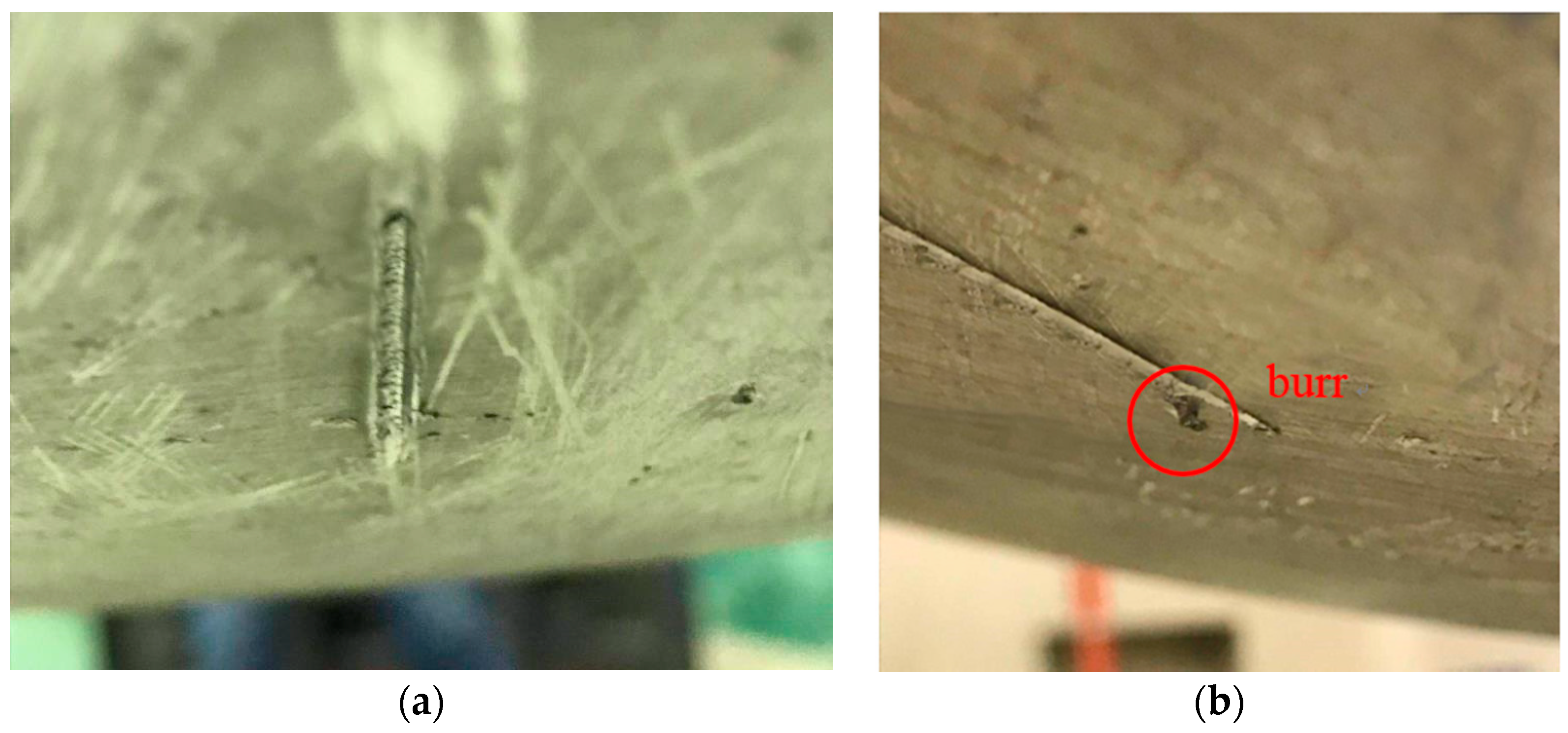
The scratches caused by friction and collision leave some metallic protrusions and roll skins. Because of their small shape and sharp corners, they are collectively regarded as burrs that can be removed by polishing to leave a smooth scratch, scratches can be regarded as elongated pits, and burrs can be considered to be protrusive triangles, as shown in
Figure 1. The research starts from the actual operating conditions, and the types of scratches can be classified into two types: scratch with burr and scratch without burr. In this research, several typical actual-size scratches with lengths of 63 mm and 130 mm and depths of 1 mm, 1.5 mm and 2 mm are selected as simulation objects to study the influence of the distribution of the electric field on the surface of the shield ball, and the influence on the discharge voltage of sphere-plane gap.
3. Experimental Work
3.1. Experimental Set-Up
The experiments were conducted in the UHVDC test base of the Hebei Electric Power Research Institute, Shijiazhuang, Hebei Province, China. The impulse voltage in the experiment was generated by a 3600 kV/360 kJ impulse voltage generator and measured using its measurement and control system. The standard switching impulse waveform (250/2500 μs) of positive polarity was adopted as the experimental voltage waveform and the efficiency of the output voltage of the switching impulses was not less than 70%. The overall experimental arrangement is illustrated in
Figure 2.
The tests and measurement methods are specified in [
15,
16]. The tests in this paper were tested and measured according to the methods specified in the literature.
Using the up and down method to obtain a 50% discharge voltage U
50%, the formula is as follows:
where:
Ui—the applied voltage, kV;
ni—the number of tests under the same applied voltage
Ui;
n is the total number of valid tests.
The standard deviation of the test σ, is calculated as follows:
A smooth shield ball with the diameter of 1.3 m was taken as the test object and the distance of the sphere-plane air gap was 2 m. The scratch was polished on the surface of the smooth shield ball in
Figure 3. According to various conditions probably occurring in actual projects, in
Figure 3a, the scratch is ground with a trowel and polished; the surface is smooth without burrs. As to the location, the scratch was at a 30° angle with the ground plane in the experiments. The scratch in
Figure 3b is not polished, and burrs of about 1 mm in length are left around the scratch. Each group of experiments was repeated 40 times and the discharge lasted for about 2.5 h. For convenience, before and after each test, meteorological conditions such as atmospheric pressure, temperature, and relative humidity were recorded. When comparing the experimental data, we used the atmospheric correction method based on parameter g, which GB/T16927.1 standard recommended to convert the experimental results to standard atmosphere conditions.
3.2. Experiments on the Discharge Characteristics of the Sphere-Plane Air Gap
3.2.1. Scratch with Burr
In this experiment, the shield ball with a scratch of 1.5 mm in depth is selected to analyze the influence of the U
50% discharge voltage of the scratch with burr, as shown in
Table 1.
As shown in
Table 1, with the 2 m sphere-plane gap length, the discharge voltage of sphere-plane gap decreases obviously when there are unpolished scratches on the surface of the shield ball. A 63-mm-long and 1.5-mm-deep scratch can lead to switching impulse discharge voltages that are 21.2% less than that for the smooth shield ball. However, a 130-mm-long and 1.5-mm-deep scratch can lead to switching impulse discharge voltages that are 40.6% less than that for the smooth shield ball. From the discharge position point of view, each test sample was subjected to 40 standard switching impulse discharge tests. Each group recorded a total of 20 discharge positions, of which 18 were located at the scratches and accounted for 90% of the total number of discharges. The amplitude of the switching impulse discharge voltage drop of the sphere-plane air gap depends on the numbers and length of scratches around the ball surface. Therefore, in order to ensure the stable operation of the valve hall of the converter station, it is necessary to specify the surface state of the shield ball so as to ensure that no visible burrs remain on the surface of the shield ball.
3.2.2. Scratch without Burr
When the scratches are polished with no burrs, the U
50% discharge voltage under different surface conditions of the shield ball is shown in
Table 2.
As shown in
Table 2, in the 2 m sphere-plane gap length, when the scratch is 63-mm-long, the discharge voltage at a scratch depth of 1.5 mm is 3.9% lower than at a depth of 1 mm, but the standard deviation is 5.39% at a scratch depth of 1.5 mm, so the scratch depth can be considered to have no obvious influence on the discharge voltage. When the scratch is 1.5 mm deep, the discharge voltage at a scratch length of 130 mm is 1.6% lower than at a length of 63 mm, but the standard deviation is 5.39% at a scratch depth of 1.5 mm, so the scratch length can be considered to have no obvious influence on the discharge voltage. From the discharge position point of view, each test sample was subjected to 40 standard switching impulse discharge tests. Each group recorded a total of 20 discharge positions, of which 2 were located at the scratches and accounted for 10% of the total number of discharges.
As can be seen from
Figure 4, when there is no burr around the scratch, as can be seen from the blue bar graph, the switching impulse discharge voltage of the sphere-plane is not significantly reduced with the change in the length and depth of the scratch; when there is a burr around the scratch, as can be seen from the yellow bar graph, the switching impulse discharge voltage of the 63-mm-long and 1.5-mm-depth scratch with or without burrs are 1621 kV and 1277 kV, which is a decrease of 21.2%. There are burrs around the scratch and a scratch without burr of the same size, and the sphere-plane switching impulse discharge voltage is greatly reduced.
4. Influence of the Scratch on the Peripheralspace Electric Field
In order to study the relationship between burrs, scratches and discharge voltage, it is necessary to establish the governing equation of the electric field and the stratification therein, as induced by the shield ball. The electric field distribution on the surface of the shield ball was calculate in the aforementioned experimental scheme. According to the surface electric field distribution of the shield ball and the maximum surface electric field intensity to determine the possible discharge position of the shield ball and the reduction of the discharge voltage.
4.1. Governing Equation
In the experiment, the 250/2500 μs standard switching impulse voltage of positive polarity was applied to the shield ball. The Fourier transform of the signals of the switching impulse voltage collected in the experiments revealed that frequency components of the impulse voltage were concentrated within 100 kHz. Owing to the test hall measuring 60 m × 40 m × 40 m and the maximum size of the test circuit being less than the one tenth of the wavelength of the impulse voltage, a method involving an electrostatic field was adopted for analysis. Moreover, the transient potential loading method was used for voltage loading. Therefore, the calculation of electric fields on the surface of the shield ball and in surrounding media satisfies the following electrostatic field equations:
where
,
, and
represent the electric field intensity in the media zone, the dielectric constant of the media, and the volume density of space charge, respectively. In the model simulation, the effect of space charge
on electric field simulation is ignored. The potential function
is given by:
In the simulation calculations, the first type of boundary condition is used for the test model:
where
is the air boundary and the ground,
is the high-potential simulation model, and
k is the multiple different boundary planes that make up the high-potential simulation model. Equations (6) and (7) form the boundary conditions of the entire electric field simulation model.
The ensuing boundary value problem for electrical fields was solved by using a finite element method (COMSOL Multiphysics (Version 5.2a, COMSOL, Stockholm, Sweden)) simulation. The model of the test hall was built according to the real size of the test hall and took the influence of large items of equipment in the test hall into account, as shown in
Figure 5a. For the shield ball with a smooth surface, tetrahedrons were adopted as the basic elements used for mesh generation for the whole model. After mesh generation, the model contained 6.14 × 10
6 elements. The calculation was conducted on a workstation with a 32-core processor and 128 GB of random access memory; each calculation took 20 min. When the maximum scratch was 130 mm on the surface of the shield ball, the length of the scratch differed from the length (60 m) of the test hall by two orders of magnitude. If adaptive mesh generation were adopted, or mesh generation were to be carried out for the whole model by controlling the mesh size of the solid surface, there would have been 3.277 × 10
7 elements, which required 3 h for each run; this increased computational burden and reduced the computational efficiency.
According to the uniqueness theorem, there is a unique solution to the Poisson equation that satisfies a given boundary condition [
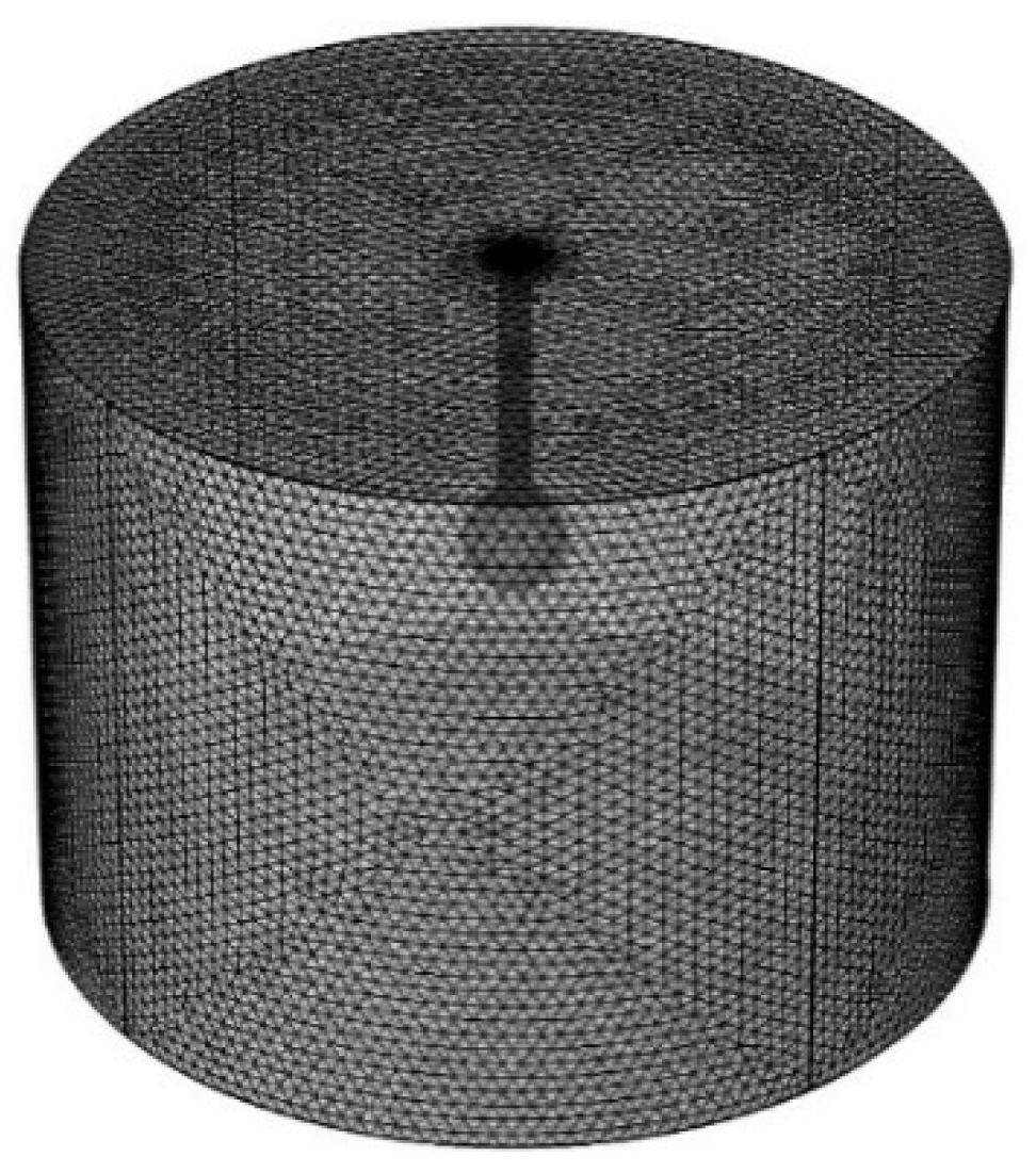
17]. Therefore, the sub-model method was adopted to improve the computational efficiency, as shown in
Figure 5b. By using the same potential loading method, considering a scratch with a length of 130 mm and a depth of 2 mm, the electric field calculated by the whole converter station model is compared with the sub-models of different simulation radii. The potential deviation is less than 1% when the sub-model has a radius of 5 m. Therefore, the sub-model with a radius of 5 m can be used to replace the whole model for simulation, as shown in
Figure 6. In this way, it only took 0.5 h for one run of the sub-model.
4.2. Analysis of the Results
Because a Φ1.3 m shield ball is usually used in 800 kV converter station valve hall in the actual project, the loading voltage of 800 kV is selected as the reference voltage by using the aforementioned sub-model and the transient potential loading method. The simulation calculations are used for the Φ1.3 m shield ball with the clean surface, with or without burr, and scratches 63 mm long, 130 mm long, 1.0 mm deep, 1.5 mm deep and 2.0 mm deep.
4.2.1. The Influence of Surface Electric Field on the Scratch with Burr
The influence on surface electric field are studied when there are small burrs around the scratches. The scratches are 63 mm long, 1.5 mm deep, and have lengths of 0.5 mm, 1 mm and 1.5 mm; burrs are arranged around the scratch. The simulation results are shown in
Table 3.
According to the simulation results, maximum surface electric field intensity at lengths of 0.5 mm, 1 mm, and 1.5 mm with burrs placed around the scratch increases by 185.2%, 323.5% and 449.2%, respectively, compared with the smooth surface. The presence of burrs around the scratches will greatly increase the surface electric field intensity of the shield ball. Through simulation calculations, when the scratches are surrounded by burrs, the maximum surface electric field intensity is greater than the maximum control field intensity of the surface of the fittings with 1500 kV/m [
18]. Therefore, in order to ensure the stable operation of the valve hall of the converter station, it is necessary to specify the surface state of the shield ball so as to ensure that no visible burrs remain on the surface of the shield ball.
4.2.2. The Influence of Surface Electric Field on the Scratch with Different Depth
The above discussion is about the change of the surface electric field intensity when there are burrs around the scratch on the surface of the shield ball. When the burrs around the scratch are removed, the scratch is 63 mm long, with scratch depths of 1.0 mm, 1.5 mm and 2 mm. The simulation results are shown in
Table 4 and
Figure 7.
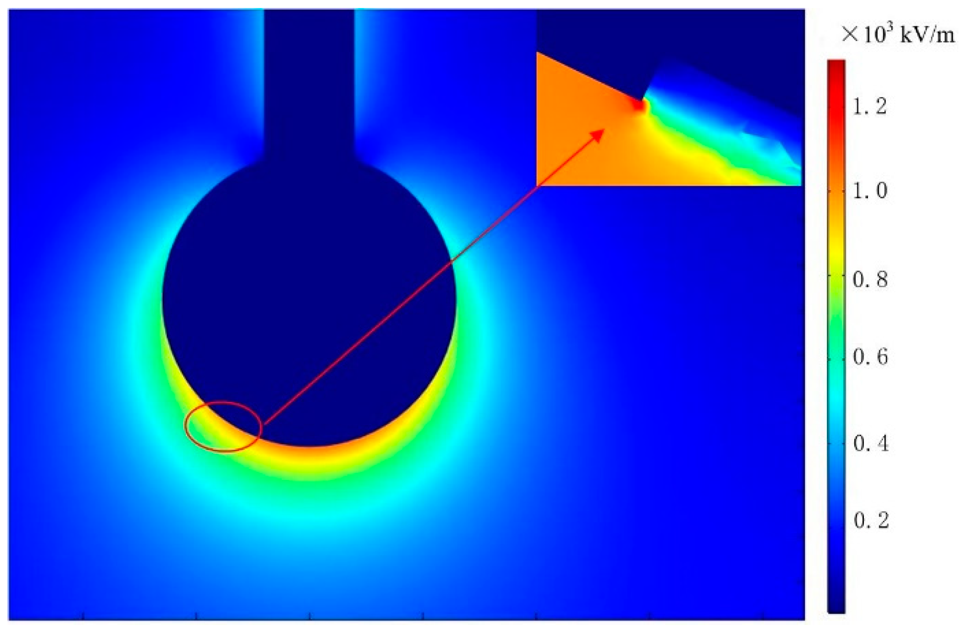
According to the simulation results, when the surface of the shield ball is smooth, the electric field distribution around it is even, the maximum surface electric field intensity is up to 1221 kV/m, which is lower than the maximum control field intensity of the surface of the fittings with 1500 kV/m. Based on the smooth surface of the shield ball, when the scratch is 63-mm-long, the maximum surface electric field intensity of the 1.0-mm-deep, 1.5-mm-deep and 2.0-mm-deep scratches are 1342 kV/m,1363 kV/m and 1360 kV/m respectively. As can be seen from
Figure 7, the surface electric field of the scratch that is sunken decreases, and the electric field intensity at the edge of the scratch increases, but the scratch edge is small for the entire shield ball, the electric field at the scratch edge is below the maximum control field intensity of the shield ball surface. The occurrence of scratches will increase the maximum field intensity of the shield ball surface, but it is still lower than the maximum control field intensity of the surface of the fittings, and the depth of the scratches has no influence on the maximum field intensity of the shield ball surface. Therefore, it can be concluded that the scratch depth has little influence on the electric field intensity on the surface of shield ball.
Comparing
Figure 4, it can be found that when the burr around the scratch is removed, the discharge voltage of the 63-mm-long and 1.5-mm-deep scratch increases from 1277 kV to 1621 kV, which represents a 26.9% increase. From the simulation results for the same size scratches, when the burrs around the scratches are removed, the electric field intensity decreases from 7486 kV/m to 1363 kV/m, which is an 81.8% decrease. Therefore, the presence of burrs around the scratches is the main cause of the reduction of the sphere-plane gap discharge voltage.
4.2.3. The Influence of Surface Electric Field on Scratches with Different Lengths
When the influences of surface electric field on the scratch with different length are studied, the scratch is 1 mm deep, and scratch lengths of 63 mm and 130 mm are examined. The simulation results are shown in
Table 5.
According to the simulation results, based on the smooth surface of the shield ball, when the scratch is 1 mm deep, the maximum surface electric field intensity of the 63-mm-long and 130-mm-long scratches are 1342 kV/m and 1366 kV/m, respectively. The occurrence of scratches will increase the maximum field intensity of the shield ball surface, but it is still lower than the maximum control field intensity of the surface of the fittings, and the length of the scratches has no influence on the maximum electric field intensity of the shield ball surface. The influence of the length on the surface electric field is the same as the depth on the surface electric field intensity, the influence of the length on the electric field intensity on the sphere surface is within the allowable range. Therefore, the simulation results can also be verified with the switching impulse discharge characteristics.
5. Conclusions
The aim of this research was to explore the influences of the scratch on the discharge characteristics of the long sphere-plane air gap under switching impulses of positive polarity. Aiming at this, the authors studied the discharge characteristics of the shield ball under different scratch conditions, as well as the distribution of the surface electric fields. The following conclusions were drawn:
- (1)
In the 2 m sphere-plane gap length, the presence of scratches with burrs on the surface of the shield ball leads to a maximum reduction of 40.6% in the switching impulse discharge voltage. The scratches without burrs on the surface of the shield ball have no significant effect on the switching impulse discharge voltage of the sphere-plane air gap.
- (2)
In the simulation results, when the surface of the shield ball is smooth, the electric field distribution around it is even. Based on the smooth surface of the shield ball, when the scratches are surrounded by burrs, the maximum surface electric field intensity is located at the scratches, a burr is placed around the scratch, maximum surface electric field intensity is up to a maximum increment of 449.2%. This is greater than the maximum control field intensity of the surface of the fittings. When the burrs around the scratch are removed, based on the smooth surface of the shield ball, the length and depth of the scratches have no obvious effect on its electric field distribution. So the switching impulse discharge characteristics can also be verified with the simulation results.
- (3)
Through experiments and simulations, it can be found that within the scope of the study, scratches have little influence on the discharge voltage of the shield ball, but the burrs greatly reduce the switching impulse discharge voltage of the sphere-plane gap. In the actual project, attention should be paid to the appearance of burrs on the shield ball, and the scratch can be maintained by grinding. The results can provide an important basis for the design and optimization of shielding fittings, and technical support for its localization.
Author Contributions
J.G. and F.L. conceived and designed the experiments; Y.D. performed the experiments; X.Y. and Y.Q. analyzed the data; Y.D. contributed reagents/materials/analysis tools; J.G. and Y.Q. wrote the paper.
Acknowledgments
This work is supported by National Key Research and Development Program of China (2016YFB0900802), and Science and Technology Foundation of SGCC “Surface Defect Influence and Altitude Correction for Discharge Characteristics of Large Size Electrode Gap in valve hall of converter station” (GYB17201600205).
Conflicts of Interest
The authors declare no conflicts of interest.
References
- Zhao, W. Engineering Techniques of HVDC; China Electric Press: Beijing, China, 2004; pp. 1–14. [Google Scholar]
- Liu, Z.; Zhang, Q. Study on the development mode of national power grid of China. Proc. CSEE 2013, 33, 1–10. [Google Scholar]
- Liang, X.; Zhang, P.; Chang, Y. Recent advances in high-voltage direct-current power transmission and its developing potential. Power Syst. Technol. 2012, 36, 1–9. [Google Scholar]
- Zhang, L.; Yang, J.; Zeng, J. Study on electric design of UHV valve hall. Electr. Power Constr. 2007, 28, 12–16. [Google Scholar]
- Hutzler, B.; Hutzler-Barre, D. Leader Propagation Model for Predetermination of Switching Surge Flashover Voltage of Large Air Gaps. IEEE Trans. Power Appar. Syst. 1978, 4, 1087–1096. [Google Scholar] [CrossRef]
- Tian, J.H.; Zhou, Y.X.; Guo, S.W.; Nie, Q.; Sun, Q.H.; Liang, X.D. Distributed parallel computation of the 3D electric field in the HVDC converter valve Hall. High Volt. Eng. 2010, 36, 1205–1210. [Google Scholar]
- Wang, D.; Ruan, J.J.; Du, Z.Y.; Huang, D.C.; Rong, R.; Du, W. Numerical Solution of the Surface Electric Field of Electric Power Fittings in ±500 kV DC Converter Station Valve Hall. High Volt. Eng. 2011, 37, 404–410. [Google Scholar]
- Ruan, J.; Zhan, T.; Du, Z.; Hu, L. Numerical Solution of the Surface Electric Field ±800 kV HUVDC Converter Station Valve Hall of Electric Power Fittings. High Volt. Eng. 2013, 39, 2916–2923. [Google Scholar]
- Ji, D.; Liu, H.; Zhang, J. Switching Impulse Characteristics for Air Gap of Valve Hall in ±800 kV Ultra High Voltage DC Transmission System. High Volt. Eng. 2014, 40, 1864–1869. [Google Scholar]
- Chen, S.; Zhuang, C.; Zeng, R.; Ding, Y.; Su, Z.; Liao, W. Improved Gap Factor of Large Sphere-plane and Its Application in Calculating Air Gap Clearance in UHVDC Converter Station. High Volt. Eng. 2013, 39, 1360–1366. [Google Scholar]
- Schneider, H.M.; Turner, F.J. Switching-surge flashover characteristics of long sphere-plane gaps for UHV station design. IEEE Trans. Power Appar. Syst. 1975, 2, 551–560. [Google Scholar] [CrossRef]
- Menemenlis, C.; Harbec, G.; Grenon, J.F. Switching-Impulse Corona Inception and Breakdown of Large High-Voltage Electordes in Air. IEEE Trans. Power Appar. Syst. 1978, 6, 2367–2374. [Google Scholar] [CrossRef]
- Wang, Y.; Wen, X.; Lan, L.; An, Y.; Dai, M.; Gu, D.; Li, Z. Breakdown characteristics of long air gap with negative polarity switching impulse. IEEE Trans. Dielectr. Electr. Insul. 2014, 21, 603–611. [Google Scholar] [CrossRef]
- Paris, L.; Cortina, R. Switching and Lightning Impulse Discharge Characteristics of Large Air Gaps and Long Insulator Strings. IEEE Trans. Power Appar. Syst. 1968, 4, 947–957. [Google Scholar] [CrossRef]
- High-Voltage Test Techniques—Part 1: General Definitions and Test Requirements; Standards Press of China: Beijing, China, 2011.
- High-Voltage Test Techniques—Part 2: Measuring Systems; Standards Press of China: Beijing, China, 2011.
- Boley, B.A. Some observations on Saint-Venant’s principle. In Proceedings of the 3D US National Congress of Applied Mechanics, New York, NY, USA, 11–14 June 1958; pp. 259–264. [Google Scholar]
- Zhang, F.; Chen, D.; Yu, J.; Guo, X.; Yue, B.; Fu, Y.; Wang, J. 3D Simulation and Optimization Design of the Electrode System of ±1100 kV Indoor DC Yard. Proc. CSEE 2017, 37, 5873–5880. [Google Scholar]
© 2018 by the authors. Licensee MDPI, Basel, Switzerland. This article is an open access article distributed under the terms and conditions of the Creative Commons Attribution (CC BY) license (http://creativecommons.org/licenses/by/4.0/).


