1. Introduction
Electric fields are employed in many engineering fields for improving aerodynamic behavior, heat and mass transfer as well as chemical reactions (e.g., in pyrolysis and gasification processes). In particular, plasmas are promising for material production (e.g., sintering, coating, nano-materials synthesis) and applications in environmental cleanup (e.g., water treatment, waste treatment, surface cleaning and disinfection). Application of electric fields in energy and process engineering can make an important contribution to the reduction of CO
2-emissions and global warming. They may reduce consumption of energy carriers, by increasing efficiency and they are useful in reduction of pollutant emissions and environmental contaminants [
1]. In the field of metrology, plasmas can especially be used for example for trace element analysis in plasma mass spectrometry (PMS) or laser-induced plasma spectroscopy (LIPS) for analysis of chemical composition of solids, liquids, or even gases. Although most applications are based on “plasma” (which is characterized by high power density), “
weak”
electric fields (characterized by low power density at which no additional ionization occurs) utilization in energy and process engineering are also discussed in this review.
Usually, plasmas can be characterized by a high power or energy density and by occurrence of “active species”, which originate from collisions of electrons and neutral molecules and subsequent chemical reactions. Those plasma-generated active species are usually characterized by higher concentrations than those produced in conventional chemical reactors [
1]. The active species include photons, neutral species, and charge carriers usually available from glow discharges and arc plasmas. However, they are not necessarily produced in dark discharges or corona). This means that, in “weak” electric fields (characterized by very low power densities), no additional charge carriers, radicals or photons are produced by ionization. In this case, only “existing” active species are utilized in an electric field (see below).
Plasmas and plasma sources are described in terms of characteristics that define their regime of operation, e.g., the plasma type, its power supply, its interaction with a workpiece and the operating pressure [
1]. Furthermore, plasma sources and regimes can be differentiated according to their spatial scale (e.g., micro plasmas) or temporal scale (e.g., nano-second (ns) pulsed plasma), etc., which can be found elsewhere [
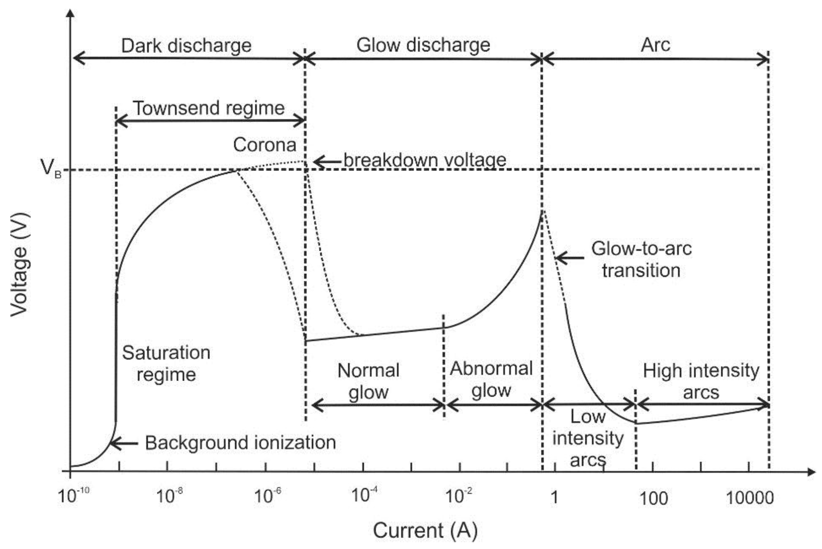
2]. Depending on the above-mentioned characteristics, the plasmas show different concentrations of active species, electron number densities, electron kinetic temperatures, etc. which are usually proportional to the input plasma power density. The direct current (DC) electrical discharges can be sub-divided according to their position on the voltage-current curve (see
Figure 1).
The three main regimes are “
dark discharge”, “glow discharge” and
“arc discharge”. The dark discharge regime on the left-hand side of this diagram is characterized by low currents. At low currents, there is a “background ionization” region in which charge carriers exist in the fluid (that are for example produced by radiation, high temperature or chemical reaction). Without an external electric field, the fluid usually remains electrically neutral as charge carriers recombine. After application of electric fields, positive and negative ions as well as electrons are separated. They drift towards the cathode and anode as unipolar ion and electron clouds. Consequently, an electric current will flow between the electrodes proportional to the applied electric field strength. Beyond the saturation regime, additional charge carriers are produced by the stronger electric field (which is also known as “secondary ionization”). The “
corona discharge” can be found in this regime, which usually is generated from a sharp point, from a fine wire or edge [
3]. The electric field gradient ionizes the medium (usually air) at the tip and a small plasma jet occurs on the conductive tip. As the generated ionized air molecules have the same polarity as the charged tip, they are repelled and form an ion cloud. This ion cloud immediately expands due to the repulsion between the ions. This repulsion of ions also creates an “
electro-hydrodynamic effect”, which is also known as
electric or ionic “
wind”. Due to the electrostatic forces, a flow is induced in the fluid showing flow velocities in the range of few meters per second. Thus, there is only a quite slow and less distinct modification of the flow properties expected [
4]. However, depending on the flow properties, even these effects can alter the thermal or acoustic boundary conditions of the technical system. This is utilized e.g., in combustors (see below) or in certain applications of heat and mass transfer, e.g., for cooling purposes. A nice overview of recent trends of ionic wind cooling for electronic elements is given e.g., in Ref. [
5]. One concept using the electro-hydrodynamic effect is the “ionic wind pump”: air induction and rotation can be generated by an assembly of corona discharges that can induce a swirling ionic wind. With this concept, tangential velocities of up to 3.3 m/s are attained, which appear suitable for adding centrifugal flow in applications like electrostatic precipitators and electrical field-controlled burners [
6].
With increasing current, the breakdown voltage is reached and the subsequent regime is classified as glow discharge. Corona or glow discharges are plasmas with lower power densities that range from below 10
−4 to tens of W/cm
3 [
1]. DC glow discharges at these intermediate currents are mainly used for sputtering with very similar phenomenology like that of low frequency RF (radiofrequency) glow discharges. DC arcs are characterized by high currents. The plasma power density of DC electrical arcs can range from 100 W/cm
3 to above 10 kW/cm
3 [
1]. Such high power density plasmas are also called
“thermal plasmas” (see below). They are in or close to thermodynamic or thermal equilibrium. They are typically used for high-temperature material processing because of their capability of heating and melting or vaporization of bulk materials. Many industrial applications using thermal plasmas are based on arc, microwave, and inductively coupled plasma discharges. Besides inductive and microwave, capacitive discharges are also typical RF plasma sources [
3]. An overview of different plasma generation methods and plasma sources are given e.g., in Refs. [
7,
8,
9].
Based on the relative temperatures of the electrons, ions and neutral molecules, plasmas can be classified as “thermal plasma” (TP) or “
non-thermal plasma” (NTP). For thermal plasmas, electrons and ions are at the same temperature, i.e., they are in thermal equilibrium with each other. The high heavy species temperatures are typically in the range of 10,000 to 25,000 K. TPs are characterized by high heat flux densities, high electron and reactive species densities. Furthermore, they show strong radiative emission. They are widely applied in industry, e.g., for arc welding, plasma spraying (“thermal sprays”) and plasma cutting. Thermal sprays are used for designing and modification of surface properties or characteristics of components commonly used in applications of energy, materials extraction and (bio-) medicine [
10]. Further plasma applications are waste treatment and gasification, electric arc furnaces (e.g., for steel production) [
9], mineral processing, nanoparticle synthesis and particle spheroidization. Another special purpose of plasmas is trace element analysis using inductively-coupled plasma—optical emission spectroscopy (ICP–OES) and mass spectrometry (ICPMS) [
2].
For NTP, the ions and neutrals temperatures are much lower (sometimes at room temperature) compared to the electron temperature. The difference of the electron energy compared to neutral energy is because of the slow energy transfer, which is explained by the small m
e/m
i mass ratio. The electron temperature is generally in the range of 10,000 K and 100,000 K (i.e., 2–3 orders of magnitude greater than the background gas) [
11]. In NTP, the electric field transmits energy to the gas electrons, which again transfer it to the neutral species by collisions. By this selective transfer of electric energy to the electrons, free radicals are generated through collisions promoting the desired chemical reactions. These reactions can be obtained with a much lower energy than that is required in a TP [
11]. NTP are created by conventional glow discharges, but also by silent, corona, short pulse, microwave or RF electrical discharges [
8].
Low temperature plasma (LTP) can be subdivided into two areas. One is the local thermal equilibrium plasma (which is also known as thermal plasma). The other one is the thermodynamic non-equilibrium plasma (also termed as cold, non-thermal plasma). In the LTP, the electrons can efficiently generate charged species, excited states, photons, and radicals. The electron energies are typically below 10 eV with small ionization degrees [
2], usually between 2 and 5 eV. There is a wide range of applications of LTP-generation in gases, liquids and for surface treatment. LTPs deliver ion fluxes to surfaces with energies up to several hundred eV enabling surface modification by sputtering, etching, activation, and deposition. One prominent application of plasma–surface interactions for deposition and removal of materials with nanometer resolution is the fabrication of microprocessors [
12]. Other plasma–surface interactions take place in particle or aerosol-laden dusty plasma leading to particle nucleation and surface growth, which is for example used for nanomaterial synthesis [
13]. In this context, the plasma generation in liquids is also relevant for synthesis of nanomaterials ranging from noble metal nanoparticles to graphene nanosheets [
14].
In the framework of this paper, four main topics of electric field applications will be addressed: the first part of the paper is about combustion applications as burners are widely used for heat generation in energy and process engineering. In this section, the production of nano-particles and the control of these formation processes are also described. Pollutant emissions such as soot, carbon monoxide (CO) or nitric oxides (NO, NO2) can be minimized directly in the combustor using electric fields. Furthermore, secondary measures of using NTP or LTP in the exhaust gas are discussed for pollutant reduction. These measures are described in the section “environmental applications”, which also deals with plasma water treatment and treatment of solid materials including waste as well as pyrolysis and gasification of coal and biomass. Another section is about electrosprays that enable many potential applications in energy and process engineering including spray cooling, nano-particle generation and mass spectrometry for trace element analysis. This is also a topic of the final section of the paper. There, diagnostics applications of electric fields will be described including laser-induced plasma spectroscopy for analysis of composition of solid, liquid and gaseous material composition. Furthermore, some tomographic approaches based on electric fluid properties for analysis of flow behavior e.g., in multi-phase flows are discussed. Laser-based techniques for studying fundamental processes in plasmas and ionic wind applications are described in the final part including temperature, concentration, and flow field measurements.
2. Electric Field Assisted Combustion
In this section, an overview of electric field (e-field) assisted combustion is given, which is limited to potential applications of burners in energy and process engineering. Applications for aerospace engines or new automotive IC engine combustion concepts (e.g., plasma ignition for usage of distributed ignition control in HCCI-engines (homogeneous charge-compression ignition) can be found e.g., in the review of Starikovskiy and Aleksandrov [
4].
Basically, the interactions between electric fields and flames have been known for a long time [
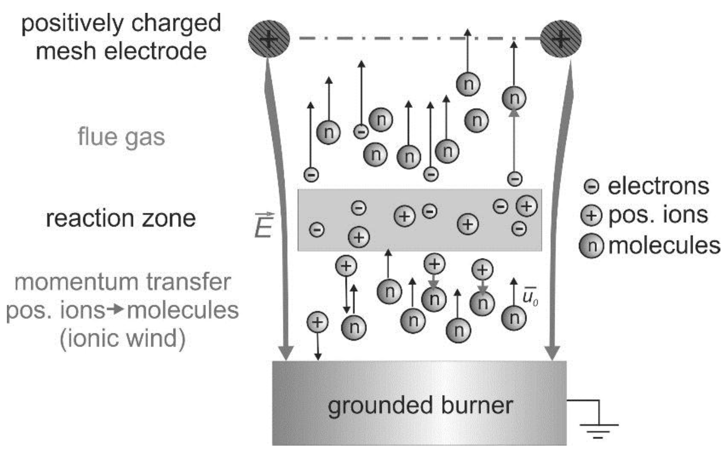
15]. These interactions are based on the existence of charge carriers produced by the chemi-ionization in the reaction zone of hydrocarbon flames [
16], which is indicated in
Figure 2. In this schematic, a positively charged mesh electrode is placed above a one-dimensional premixed “flat” flame.
Without an external electric field, flames are usually electrically neutral. The charge carriers recombine downstream the reaction zone. However, after application of electric fields, the charge carriers are separated and an electric current will flow between the electrodes depending on the applied voltage. If the burner acts as the cathode, then the positive ions are accelerated towards the burner. The negative ions and electrons move downstream towards the anode. The charge carrier density in the flame front of premixed hydrocarbon-air flames is approximately 10
9–10
10 cm
−3 (depending on the flame stoichiometry and boundary conditions) without an external ionization source [
16,
17,
18]. Further details about the electrical structure of flames can be found in Refs. [
19] and [
20]. No appreciable ionization occurs if the electric field strength is below the gas breakdown threshold value [
4]. Stronger discharge in electric-field assisted combustion, such as nanosecond discharge, microwave discharge, dielectric barrier discharge, and gliding arc, etc. can modify the chemical reaction route, which could affect the flame structure as well.
For relatively weak electric fields (or a low reduced field strength E/n), mainly the ions generated in the flame front are accelerated in the electric field. This leads to a momentum transfer between the positively charged ions and the neutral gas molecules. These collisions are responsible for flame modifications due to the induced hydrodynamic backpressure [
16]. These forces are known as “ionic wind” or “electrically driven convection” (see e.g., [
6]). Electrons play a minor role in momentum transfer in the flame front because of their low mass. Similarly, the effect of negative ions is relatively low due to their lower concentration. Because of collisions between ions and fresh gas molecules, a shift of the flame front appears.
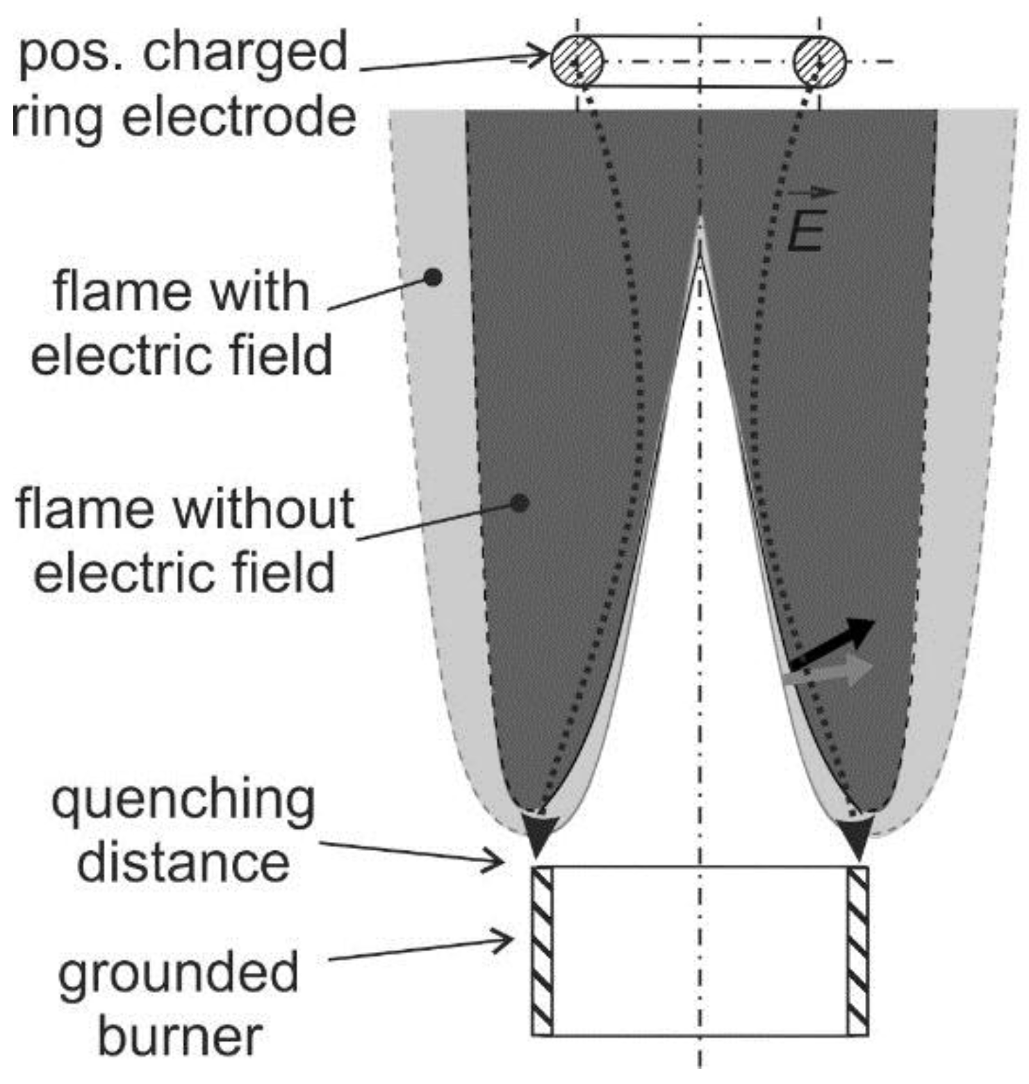
The ionic wind is mainly used for flame stabilization and minimization of pollutant emissions. Furthermore, the ionic wind can be used to affect the flame–wall interaction. This is useful to avoid flame quenching at the wall or for controlling the heat transfer from the flame to the wall, which is discussed in [
21]. Usually, a charged electrode and a grounded burner are utilized for generation of an electric field that is arranged longitudinally to the flame (see a schematic in
Figure 3). In case of a positively charged electrode, the flame front is slightly pushed back to the burner. This causes the electric field enhanced combustion that is reported in
Section 2.1 (flame stabilization) and
Section 2.2 (pollutant minimization). This mechanism could also contribute to a controlled growth and aggregation of nano-particles in flame synthesis described in
Section 2.3.
Many fundamental experiments using lab-scale burners have been carried out for studying electric field enhanced combustion using premixed (see, e.g., [
22,
23,
24,
25,
26,
27,
28,
29,
30]) and non-premixed flames [
31,
32]. Attempts for a technical application at higher thermal load were conducted by Weinberg et al. for a meso-scale burner [
33], by Sakhrieh et al. for a Bunsen flame array [
34] and Altendorfner et al. [
35] for a swirl flame that is usually applied in gas-turbine burners. Usually, in these studies the electrode was positioned close to the flame inside the combustion chamber. However, also capacitive coupling of electric fields was explored in Ref. [
35] for non-intrusive integration of mechanical parts into existing technical combustors (e.g., of gas turbines). Electric fields could be transmitted through ceramic walls of the combustion chamber for possible realization of flame control. In this case, electrodes were deposited as coatings on the walls, thus avoiding sensitive mechanical parts in the hot combustion chamber.
2.1. Flame Stabilisation
The flame structure and the flow field can be significantly changed by the ionic wind. As indicated in
Figure 3, a laminar Bunsen flame can be pushed towards the burner when a positively charged electrode is applied. Maximum local flow decelerations between 0.8 and 1.6 m/s [
27] were observed at the bottom of a laminar premixed Bunsen flame and in the post oxidation zone depending on the flame stoichiometry. This is significant as the flow velocity at the burner outlet is in the range of 2.0 m/s. At maximum applied voltage of 6 kV, in the fuel rich premixed flame (air–fuel ratio, AFR = 0.8), the deceleration is maximal while in the lean flame (AFR = 1.2) the deceleration is lowest. This flow modification indicates that the ionic wind can be utilized for flame stabilization, which is discussed in the subsequent paragraphs.
The flame stability can be improved in terms of increased lean blow-off-limit of (ultra) lean flames [
34,
35] and by reducing the lift-off height of non-premixed flames [
36]. In general, premixed flames stabilize at that position where the incoming velocity of the gas mixture and the flame speed are in balance. In case that the gas velocity becomes too high or the fuel/air mixture becomes to lean (followed by a reduced flame speed), the flame tends to lift off the burner and/or will finally blow off. Altendorfner et al. [
35] showed that an electric field could lead to an increase of the lean blow-off limit of up to 8%. The maximum AFR without electric field was 1.14. Applying a voltage of 5 kV increases the AFR at blow off to 1.19, and a voltage of 17.5 kV increases it to 1.23. At the same time, this larger relative air–fuel ratio (AFR) leads to an overall decrease of NO
x emissions by 40% (see discussion below). In case of a Bunsen flame array produced by a 7-hole burner studied by Most et al. [
37], the outer lifted flames are mainly affected by the electric field. The reaction zone of the lifted outer flames were shifted upstream, i.e., the gap between burner and lifted flame can be narrowed which reduces emissions of unburnt hydrocarbons and CO (see also discussion in
Section 2.2).
Furthermore, thermo-acoustic oscillations [
26,
28,
38] can be suppressed or generated [
38,
39,
40] by using electric fields and, currently, this topic is of high interest. Thermo-acoustic oscillations may occur in the combustor at a certain load and could potentially damage the burner and combustion chamber [
41]. Electric fields were proposed for modification of the acoustic flame behavior. Volkov et al. [
28] changed the flame oscillation frequency by application of high electric field strength. A varied flame speed by about 2.5% was noticed; however, the high field strength also leads to secondary ionization. Lacoste et al. [
38] studied laminar methane-air flames and its responses to acoustic waves, AC (alternating current) electric fields, and 10-ns 10 kHz glow discharges. The flames chemiluminescence was found to be responsive to an AC electric field in a wide range of frequencies, which is explained by the ionic wind. The gain of the transfer function for plasma forcing was up to five times higher when compared to acoustic forcing. In Ref. [
42], a nano-second pulsed plasma discharge (NSPD) was also utilized for stabilization of a premixed methane/air dump combustor. It was concluded that the flame shape determines the effectiveness of the plasma-induced flame stabilization. Especially noisy, outer recirculation zone stabilized flames can be significantly improved by using NSPD.
However, weak DC electric fields could also be used to dampen these flame oscillations [
26]. For suppression of these instabilities, the flame response time on the electric field must be known in order to determine the capability of the electric field to vary the flames “convection time” and oscillation frequency. Up to now, only a few experiments for the quantification of the ionic wind were conducted [
33]. For this purpose, the temporal behavior of the flame structural modifications and flow changes in the flame are studied in fundamental experiments using optical diagnostics (see also
Section 5).
Sun et al. [
35] used high-speed photography for studying the flame response of a flat-flame in an electric field. They observed first flame luminosity changes 2 ms after activation of the e-field, whereas the total flame response duration was about 36 ms. Laser-based experiments were conducted for laminar premixed Bunsen flames in a weak DC electric field. The e-field was generated using a positively charged ring electrode above the flame. Planar laser induced fluorescence (PLIF, see also
Section 5) of the OH-radical was applied for visualization of the flame structural changes. Furthermore, particle image velocimetry (PIV) was used for measurement of the flow field variation in the flame that was subjected to the electric field. It was described that the flame responds to the e-field within 2–4 ms [
25,
26], while the shape of the flame was not significantly changed. After activation of the electric field, a disturbance was initialized at the bottom of the flame. This disturbance propagates downstream in an axial direction in the form of a wave-like oscillation.
In experiments of Schmidt et al. [
43,
44], the pulsed electric field leads to stronger changes of the flame structure. For a laminar premixed flame, it was reported that turbulent flame front wrinkling occurred when an electric field was applied using a pin electrode. It is mentioned that the flame was “fully crushed” [
42] showing an unstable behavior. In Refs. [
25,
26], it was shown that the flame can adopt the frequency of a transient weak electric field up to 200 Hz. For 200 Hz, the period between activation and deactivation of the e-field is much shorter than the flame response time (which is about 2–4 ms, as mentioned above). Thus, the influence of the e-field is very weak. Because of that, a limiting frequency of the ionic wind in the range of 100 Hz was derived. In studies applying high voltage AC-electric fields to premixed flames, flame oscillations were produced even for frequencies up to 1000 Hz [
30]. However, secondary ionization that occurred at relative high electric power limits technical applicability.
In Ref. [
26], the potential of e-fields for suppression of acoustic flame instabilities was studied using a 1D-flame. Acoustic oscillations were generated by a fuel injector with defined injection frequencies leading to a periodical lift of the flame. High-speed detection of the flame chemiluminescence was used to characterize flame oscillations. When a static weak e-field was applied, the duration of flame oscillation could be reduced by up to 54%. This means that the flame oscillations can be shifted to higher frequencies. This frequency range could be less critical for combustion systems. Besides static electric fields, transient fields at different frequencies could also be used for suppression of certain thermo-acoustic oscillation frequencies. However, this was not studied so far and remains an open research topic for future studies.
2.2. Electric Fields for Controlling Pollutant Emissions of Flames
Electro-hydrodynamic effects induced by weak electric fields are applicable to control pollutant formation in flames. Main pollutants such as unburned hydrocarbons (UHC), CO- and NO
x as well as soot can be minimized using the “ionic wind effect” without secondary ionization. A characteristic property is its relatively low electric power consumption compared to the corona discharge regime. For example, in Ref. [
45], it is reported that the corona mode operation requires up to 500 times the energy needed for the ionic wind mechanism. The electric power required for the ionic wind mechanism to enhance combustion was found to be in the range of 0.01% to 0.001% of the used thermal power (see, e.g., discussion in Ref. [
34]). Effects of secondary ionization (i.e., when the applied voltage is above the saturation regime), which modifies the flame chemistry [
28] and formation of pollutant emissions, are not the focus of this survey.
A decrease of the CO-concentration by one order of magnitude was measured using an e-field in various diffusion flames [
32]. In turbulent premixed flames, electric fields lead to a reduction of CO-concentrations by 95% at technical relevant conditions, e.g., high pressure (up to 1 MPa) and thermal loads above 40 kW (see Refs. [
34]). However, an increase of the NO-concentration by about 25% occurred [
34]. Nevertheless, as the overall lean blow off limit can be shifted by about 8% towards leaner operation, this leads to combined reduction of CO and NO
x emissions by about 60% and 40%, respectively [
37].
In Ref. [
37], a Bunsen flame array produced by a 7-hole burner was studied that was exposed to an electric field. The outer flames tend to lift and thus produce rather high amounts of CO and unburned hydrocarbons (UHC). It is assumed that the gap between the flame and the burner head due to the flame lift is responsible for high CO and UHC-emissions. Unburnt fuel and UHCs may escape through that gap. By using electric fields, this gap can be reduced, which reduces these emissions [
37]. The electric power necessary to achieve an effective 90% reduction of CO emission was 0.002% of the overall thermal power of the burner. In [
35], similar effects were achieved for an aerodynamically stabilized swirl flame that showed similar dependency of the reduction of CO and UHC emissions on the applied voltage. Furthermore, the flame cone angle increased with the electric field strength. In general, the reduced CO- and UHC-emission can be also explained by the modified flow field in the flame and increased residence time of the gas molecules in the flame [
24]. Furthermore, a higher flame temperature is expected as also increased NO
x-emissions were observed when electric flames were applied to flames [
34]. For clarification, manifold fundamental studies were conducted in lab-scale flames using various optical diagnostics [
24,
25,
26,
27] (see also
Section 5).
In case of low electric field strengths without occurrence of secondary ionization, the temperature increase must be related to the changed flow in the flame due to the ionic wind. For the case of a positive voltage applied to the downstream electrode, the flame is pushed toward the burner surface due to the ionic wind (see also
Figure 3). In turn, the flame heats the burner and the fresh gas as well, followed by an increased flame temperature. At the same time, the post-oxidation-zone is also broadened. In Ref. [
27], laser-based temperature measurements were conducted to verify these effects. Vibrational CARS (coherent-anti-Stokes Raman spectroscopy) was utilized for non-intrusive temperature measurements. When the e-field is activated, the maximum temperatures in the flame were increased by about 40–110 K for different AFR. As the flame is pushed towards the burner, an increased inlet gas temperature of up to 20 K was observed. This is especially significant for the rich premixed flame. These measurements in the burner were conducted using thermocouples inside the burner. The observed temperature increase in the flame and exhaust gas must be a secondary effect. This occurs because of the changed flow field induced by the ionic wind. Furthermore, the lowered flow velocity leads to an increased residence time of the molecules in the hot broadened exhaust gas. This explains a better burnout of UHC and CO and consequently, a reduction of these pollutant emissions. Both higher flame temperature and longer residence time can explain the larger NO
x-emissions and reduced UHC and CO-emissions after activation of the e-field.
Furthermore, electric fields can have a significant effect on nanoparticle formation in flames. Especially, soot formation in IC engines and technical combustors is a challenge, which is discussed in the subsequent section. Besides the soot formation, especially the production of technical nanoparticles produced via flame synthesis is addressed, as it is an important topic in process engineering.
2.3. Electric Fields for Controlling Nanoparticle Characteristics
The chemically and thermally ionized species of the flame are also involved in the growth dynamics of particles formed in flames. In Ref. [
46], it was shown that the influence of charging on particle growth dynamics is more distinct when the ion concentration is at least comparable to the particle concentrations. This charge distribution can be adjusted by using electric fields, which could be an interesting application for controlling the particle coagulation in flame synthesis, for enhancing combustion of solid fuels or even for minimization of particle emissions in sooting flames. Thus, in this section, first a brief summary is given for applications of electric fields to control nanoparticle formation in flame aerosol technology, and, second, to reduce soot concentrations.
Flame synthesis refers to the formation of fine particles from gases in flames. Large-scale production of carbon blacks and ceramic powder such as silica, titania as well as zinc oxide and alumina powders is possible [
47]. Electric fields can be used to affect nanoparticle characteristics such as size of primary particle and agglomerates, and the crystallinity of nanoparticles. Applied in flame synthesis, they offer the unique opportunity to control size distribution, composition and morphology [
47]. In particle-producing flames, the velocity difference of the fuel and oxygen jets determine reactant mixing and flame quenching and thus the average primary particle diameter [
48]. This means that the residence time and the history of the particles in the flame is varied by modification of the flow field; however, this can also be affected by external forces. As mentioned in the previous sections, the local flow velocity and thus the residence time in the flame can be affected by electric fields. Consequently, the nanoparticle growth in the reaction zone and the particle size can be controlled. Furthermore, electric fields can directly affect the history of synthesized nanoparticles as they can charge newly formed nanoparticles [
47]. The electrodes attract oppositely charged ions that attach onto the formed particles. This again leads to retardation of their collision and growth. The electrophoretic force varies the drift velocity of the particles and particles are removed from the flame towards the external electrodes. Furthermore, electrostatic dispersion reduces the coagulation rate between charged nanoparticles in the high temperature region of the flame in the electric field [
47,
49].
Hardesty and Weinberg [
50] studied fly ash removal from sooting flames. They observed a reduction of the primary particle size of the produced silica of up to a factor of 3 with increasing voltage. This was explained by the reduced residence time for particle sintering because of the fast particle deposition on the electrodes. In contrast to this study, Katz and Hung [
51,
52] found a larger particle size when an electric field of 1.2 kV/cm was applied in an H
2/O
2 counter-flow diffusion flame. The data showed a 3- to 10-fold increase in the diameter of the TiO
2, GeO
2 and GeO
2 particles produced for application of an electric field.
Pratsinis and coworkers investigated different flame geometries with electric fields applied perpendicular to the flow direction (see, e.g., [
53,
54]). Corona discharge was generated using needle shaped or plate electrodes for charging the particles. Furthermore, it serves for reduction of the residence time through ionic wind effects by mixing of the flows. Corona discharge is characterized by relatively high field strength above the saturation voltage threshold. This means secondary ionization occurs and sufficient charge carriers are generated for charging particles (see also discussion in Ref. [
46]). It was concluded that an increased electric potential reduced the particle size. In the studies presented in Refs. [
53,
54], it was found that the e-field generated by needles determined most significantly the product powder characteristics. This is obviously induced by significant modifications of the flame shape and generated turbulence. The strong effect of electric field produced by needle-electrodes is also in accordance with data presented in Ref. [
43]. This showed a distinct wrinkling of a premixed flame surface that turns from a laminar into a turbulent-like shape when an electric field was applied using similar pin-electrodes.
In Ref. [
54], it was mentioned that a limited soot formation was found when an e-field was applied resulting in gray colored powders. It is mentioned that the soot content increases up to 1 wt % with larger electric field strength regardless of the electrode geometry or polarity. The authors explained this by the broad residence times of the particles in the high-temperature zones of the flame. This is due to the ionic wind that also enhances the flame turbulence. It was reported that the flame temperature (measured by using K-type thermocouples) decreases up to 400 K with increased field intensity, which was mostly because of the turbulence induced by the ionic wind. At the same time, the larger soot content with increasing potential is a result of the reduced particle residence time at high temperatures. This is because the soot particles are drawn out of the high-temperature flame zone by repulsive forces and by the ion wind [
50].
In general, soot production and soot emission from technical flames are unsolved issues, which could be counteracted by using electric fields. In diffusion flames, electric fields have been shown to affect the process of nucleation, growth in the pyrolysis zone, and the deposition of particles [
55]. This topic was studied in several experiments for different electrode and burner configurations. Place and Weinberg [
55] studied the effect of an e-field on soot formation in a counter-flow diffusion burner. They found that an increase of the electric potential to 1 kV lead to a reduction in the soot formation of 2%. By using a counter-flow flame with the burners as electrodes, it is possible to draw both positive and negative ions from the flame through the pyrolysis zone. It is mentioned that particles acquire their charge very early in their history. As the particle growth is controlled by their residence time in the pyrolysis zone, this can be affected by the applied field strength.
Wang et al. [
56] studied the soot distribution of a non-premixed ethylene/air flame of a McKenna Burner in an electric field. Laser-based techniques were applied to measure variation of soot volume fractions and particle morphology for varied residence time, which is controlled by an electric field. It was found out that most soot particles are positively charged in accordance to Ref. [
55]. The size of the produced agglomerates depends on the field strength. A negatively charged plug above the burner attracts the positively charged particles and decreases their residence time. Consequently, both particle formation and oxidation processes are shortened on average. A positively charged plug showed the opposite effect.
Still, these processes need further investigation to separate the influence of the ion wind on the flame and the electrophoretic effect on the transport behaviors of nanoparticles for improved understanding. Some fundamental studies for deeper insights into these processes are reviewed in [
49]. However, it is mentioned that the electrostatic dispersion effect on particle cannot be easily separated from ionic wind effects and this topic needs further investigations.
3. Environmental Applications
Ozone generation and electrostatic precipitation (ESP) are the most important industrial applications of atmospheric pressure non-thermal plasma (NTP) in environmental remediation [
1,
9]. However, still significant research efforts are necessary for improving the efficiency of these processes. ESP is the device of choice for controlling particle emissions of many industrial applications. Ozone (O
3) is applied as a disinfectant and oxidant for water treatment, but it also plays a major role for plasma oxidation of NO [
57] and particulate matter (PM) [
58]. NTPs were utilized for treatment of volatile organic compounds (VOCs) as well as short- and long-chained hydrocarbons [
59,
60]. Thus, NTPs are promising for exhaust gas treatment for automotive and industrial applications. Furthermore, they are applied for conversion of carbon dioxide (CO
2), methane (CH
4) and syngas (consisting primarily of hydrogen (H
2), carbon monoxide (CO), and some CO
2) into hydrocarbons [
61,
62]. Thermal plasmas have also been used for plasma gasification, which is already applied in industry, e.g., for waste treatment [
63]. Potential future technologies could include plasma sterilization and decontamination of surfaces and liquids including applications in food industry and for wastewater processing, whereas only the latter one is briefly discussed in this paper.
3.1. Plasma Utilization for Pollutant Removal in Flue Gas
Flue gas of technical burners, gas turbines, and IC engines contain a variety of pollutants due to incomplete combustion of hydrocarbons. This means that the ideal state of the thermodynamic equilibrium cannot be reached because of too short combustion times, the lack of mixture homogeneity and rapid variation in the temperature field. Especially, diesel engines are used widely for power generation in industry with nitric oxides being the main pollutant. The exhaust gas is far leaner than that of gasoline engines and contains far less unburned hydrocarbon and CO. Furthermore, also PM emissions are more problematic for diesel engines compared to conventional spark-ignition gasoline engines (mainly equipped with port-fuel injection systems for homogeneous mixture formation). However, Direct-Injection Spark-Ignition engines (DISI, sometimes also termed GDI, Gasoline Direct Injection) may show high PM emissions as well, especially during cold-start of the engine and other operating points with very late injection leading to local fuel-rich mixture and/or wall wetting [
64,
65]. Additionally, during combustion of solid fuels such as biomass, coal and waste further pollutants such as ash, SO
2, dioxin, furans, and Hg
0, etc. are emitted.
There are many primary measures to reduce formation of pollutants during combustion (such as Exhaust Gas Recirculation EGR, high pressure fuel injection and multiple injections in IC engines, lean combustion, etc.). Besides that, several secondary measures have been applied for NOx removal from flue gases. This includes Selective Catalytic reduction (SCR), active lean NOx catalysts, or lean NOx trap catalysts. For example, SCR is used to convert NOx into molecular nitrogen, and water, using a catalyst and ammonia (or “urea”). However, SCR catalysts need high temperatures of around 300 °C for activation. There are additional challenges, e.g., the possibility of ammonia leakage, catalyst poisoning, and the need for refilling of urea in automotive applications, etc.; furthermore, besides diesel engines, the simultaneous removal of multi-pollutants from coal-fired power plants was forced during the last years. Non-thermal plasma technologies for flue gas cleaning perform well on SO2, NOx, and Hg0 removal. Extensive studies have been carried out and some examples are provided in the subsequent section.
3.1.1. Removal of NOx and VOC
In Ref. [
66], a nice review is given on the research progress of pollutants removal from coal-fired flue gas using NTP. It is summarized that most of the large-scale demonstrators of NTP technologies focus on SO
2 and NO
x removal. One large industrial demonstration based on a pulsed corona discharge is operated in China at a maximum flue gas capacity of 50,000 Nm
3/h. For a flue gas flow of 40,000 Nm
3/h, the removal efficiency of SO
2 and NO
x of this demonstrator are more than 90% and 40%, respectively, without additional catalyst [
67]. Dielectric barrier discharge (DBD, see below) reactors can be combined with ammonia scrubber and wet electrostatic precipitator (see below) for simultaneous removal of SO
2, NO
x, PM
2.5 and Hg
0 from the flue gas. One such device was constructed by Powerspan Corporation (Portsmouth, NH, United States) (which is a 50 MW “ECO” commercial demonstration unit in the R.E. Burger power plant) and the removal efficiency can be up to 98% (SO
2), 90% (NO
x) and 85% (Hg
0), respectively [
66]. However, most of the studies on Hg
0 removal via the NTP process are still in the laboratory stage and commercial scale research is rare [
66].
NTPs are advantageous because physical and chemical processes can be induced at relatively low gas temperatures. Under these conditions, catalysts or adsorbers will not work properly [
59]. By using NTP, a selective transfer of the input electrical energy to the electrons is possible. This generates free radicals through collisions promoting the desired chemical reactions in the exhaust gas. These reactions can be gained with much lower energy compared to a thermal plasma reactor [
11]. All kinds of power generators (AC, DC and pulse) can be used for plasma generation, while AC and pulsed NTP show superior NO
x removal efficiency and pulse energization is found to be more energy efficient [
60]. NTP produces chemically active species, which are generated by the dissociation and ionization of the ambient gases. This includes O
3 (ozone), O (oxygen radical), N (nitrogen radical) and OH (hydroxyl radical). Furthermore, N* (excited nitrogen radical) and N
2+ (nitrogen ions) are produced. Plasma treatment of flue gases comprise NO oxidation to NO
2. This is an important intermediate step in the reduction of NO to N
2 [
60,
68]. The oxidation of NO to NO
2 usually requires O
3 that is produced in the plasma:
while the main NO
x-removal reactions involve NO
2, N, metastable N
2 or N
2O, etc. [
60], e.g.,:
However, the reaction paths change significantly in the case that hydrocarbons are available in the flue gas because of reactions between NO
x and HC. Furthermore, the presence of carbonaceous soot in the diesel exhaust gas changes the reaction, as the NO-NO
2 conversion is less probable. In this case, the O/OH radicals are consumed; however, NO
2 can react with soot [
69] (see also discussion below). The most efficient way is the application of a plasma reactor along with an additional catalyst reactor. In the presence of the plasma and HC, the oxidation of NO to NO
2 takes place [
60]:
In the second stage, NO
2 is reduced to N
2 by selective reduction using the catalyst and HCs [
60]:
Few studies exist on PM removal of diesel engines using NTP. In Ref. [
58], NTP technique has been utilized for PM minimization in the exhaust gas of an 6-cylinder 162 kW diesel engine using a DBD reactor. Ozone strongly promotes PM oxidation leading to increased formation of CO
2. Additionally, PM is incinerated by NO
2, and activated oxygen components. PM concentration removal of more than 50% was possible and a maximal discharge power of 60.1 W and a specific energy density of 300 J/liter (which is the discharge power divided by the mass flow rate) have been obtained at 21 kV and 10 kHz.
Usually, corona discharge reactors or DBD reactors are used for NTP generation (see for example
Figure 4). In a corona discharge reactor, a non-uniform electric field is generated between two concentric electrodes. These electrodes are characterized by sharp edges or points. The discharge occurs usually as a streamer. The ionization zone is spread over the entire discharge gap, which can be in the range of 10 cm (or more) being suitable for large-scale reactors [
70]. At higher electric field strengths, the formation of a spark can be solved by using pulse voltage circuits. This also can prevent plasma from transition to the thermal mode and arc formation.
DBD reactors consist of a couple of electrodes with at least one dielectric barrier in between. Due to the dielectric barrier, the discharges require higher voltage to cause the breakdown in the gas. The material of the dielectric barriers is usually quartz glass, silica glass, or ceramic materials. Thin enamel or polymer layers are used in special cases [
71]. In both DBD and corona discharge reactors, small scale electron streamers are formed. However, a DBD produces a homogenous discharge with low energy consumption, which is usually a “silent discharge” [
60]. In DBD, the formation of stable and homogeneous discharge is easily possible. The DBD reactor is scalable, effective, and has low operational cost so that DBD are applied more frequently than other types of reactors for flue gas cleaning from CO, NO
x and VOCs. Furthermore, DBD have been used for a long time for ozone generation [
60].
Plasma can be combined with a catalyst (also called “
Plasmas assisted catalysis”) e.g., in packed bed system for decomposition of VOCs, for oxidation of carbon soot, NO and CO as shown in Ref. [
72]. The dielectric packed bed reactor is similar to the DBD. However, the dielectric pellet material is placed in the gap between the barrier and the electrode. Relatively low voltages are applied for generation of a plasma over a relatively large electrode distance [
60]. The packed bed uses a layer of ferroelectric pellets with a diameter of a few mm. The contacting points of the pellets are ionized. After exposing the pellets to an electric field, a spontaneous polarization occurs. This results in a high field strength at the contact points of the pellets [
60]. The packed bed can be applied for plasma-assisted combustion in future, while the decomposition of volatile organic compounds (VOCs) by plasma-assisted catalysis was already demonstrated e.g., for the conversion of toluene, phenol and MTBE (methyl tert-butyl ether) in air streams by using NTP [
73].
Besides pellet-type catalysts, honeycomb catalysts can also be applied e.g., for NO
x control of vehicle exhaust gases that are characterized by a lower pressure drop and are less affected by mechanical vibrations. For homogeneous generation of the electrical discharge across the honeycomb, a sliding discharge was proposed [
72] that ionizes the gas inside the fine channels. However, further understanding of the interaction of NTP and solid/liquid surface is necessary before it could lead to various applications. Packed bed reactors with suitable catalysts are also promising for fuel reforming and CO
2 conversion. For higher conversion efficiency of these stable molecules, gliding arc and microwave discharges are proposed. They are characterized by high ionizing rates and form highly non-equilibrium plasmas [
2]. Fridman et al. [
8] demonstrated the gliding arc reactor for concentrated gas endothermic processing used for total incineration of H
2S-rich waste gases. It is mentioned that this technique can be operated at a low energy cost, especially for processes with high-CO
2 gas mixtures. Furthermore, “low energy, non-catalytic approaches” [
8] for generation of syngas from natural gas and CO
2 (or directly from a biogas) was demonstrated.
Most of the presented studies on pollutants removal using NTP were conducted on laboratory-scale test benches, many of them using synthetic flue gas [
57,
59,
60,
74]. According to these publications, energy consumption and cost of the plasma generation are the main challenges of using NTP for pollutant removal [
74]. The required large energy input in most cases corresponds to an adiabatic temperature rise of several hundred Kelvin [
73]. However, NTP technology for pollutant removal is predicted to become commercially viable in the future. However, for this, further research is necessary for improvement of the electrical aspects and the reactor design.
3.1.2. Electrostatic Precipitation (ESP)
Electrostatic precipitation (ESP) is a very efficient way of removing particulate matter from exhaust gases without a large pressure drop (usually <1000 Pa) and is extensively used in industries to limit particulate emissions [
75,
76]. The collection efficiency can be >99% while sub-micrometer particles can also be collected effectively.
The ESP setup consists of discharge electrodes and collecting electrodes. After applying high voltage DC to the discharge electrode, a corona discharge produces ions and electrons. These charge carriers attach to particles, which are accelerated towards the collecting electrode by a Coulomb force. These particles are collected on that electrode and create a solid particle layer, which needs to be removed (either by mechanical shock impulse rapping or by water washing (wet precipitator) [
76] when it reaches a certain thickness, as the collection efficiency drops significantly. Furthermore, the collection efficiency depends on many factors, such as the geometry of the electrodes, the voltage applied, and the characteristics of dust particles. For example, the efficiency for collecting particles with 0.1 to 1 µm diameter is smallest, while it increases for much smaller and large particles. Further discussion and details on particle collecting efficiencies can be found elsewhere [
75,
76]. According to their applications, ESPs are classified in terms of electrodes geometry (one stage, two stage) and the shape of collecting electrodes (cylindrical type, plate type). Furthermore, they can be distinguished according to the direction of gas-flow (vertical gas-flow, horizontal gas-flow) and the addition of water (dry and wet precipitator). In the wet ESP, water spray or running water on the collecting electrode allows higher performance because the re-entrainment of collected particles can be eliminated, and, at the same time, gaseous pollutants can be absorbed. Non-thermal plasma can be generated by using pulsed energization, which also promotes chemical reactions for treating gaseous pollutants such as NO
x and VOC (see above).
ESP are widely applied in industry, e.g., for incineration, boilers, cement production kilns [
76], and for cleaning of indoor air [
75]. Furthermore, they are recently applied for PM reduction in the exhaust gas of diesel engines [
77], for small-scale biomass furnaces [
78], in coal pyrolysis furnaces and coal-fired power plants to reduce fly ash [
79], etc. In Ref. [
77], an ESP was used for a small diesel engine (9.5 kW) and high average particle collection efficiencies of up to 97% were reached for electrical power values ranging from 10 W to 30 W. For the discharge electrode, different effective lengths of 0.4–1.4 m were studied, and average collection efficiencies of 61.3–95.5% were achieved. In Ref. [
78], the precipitation efficiencies of two different types of ESP were studied for three biomass fuels of different particulate emission levels. A chimney top system with manual cleaning was compared to an inline system with automated cleaning. Precipitation efficiencies of >70% were possible in an inline system with automated cleaning. The chimney top ESP (with manual cleaning system) showed high efficiencies of 69–86% on a short-term basis. For low emission fuels like wood, acceptable precipitation efficiencies of about 70% were achieved and maintained over a long period. For medium and high emission fuels, the use of an automated cleaning system was necessary to maintain acceptable precipitation efficiencies. In the chimney top type, system efficiencies dropped to zero with high emission biomass fuels after 50 h and 10 h, respectively, in the case of no cleaning.
In Ref. [
79], the particle collection efficiency was studied for two different fly ash types that were produced from a coal pyrolysis furnace and coal-fired power plant. From 363 to 523 K, the collection efficiencies were above 95% of for both ash samples. However, at 623 and 723 K, the collection efficiency decreased and they were different for the two ash types studied. For enhancing particle removal, particle conditioning was applied to reduce particle re-entrainment. This was done by adding fine calcium carbonate powders as conditioning particles.
In Ref. [
80], the solid particle removal was studied using an ESP in the flue gas of a 50 kW wood pellet boiler and a 100 kW gasifier. The obtained collection efficiency of the ESP was ~98–99% during the investigation using the ESP in the flue gas of the boiler. A lower maximum efficiency for the electrostatic precipitator of ~75% was observed for the gasifier, as particles are larger and show higher concentrations than those obtained after combustion in the boiler using the same type of wood pellets.
3.2. Plasma Water Treatment
Plasma generation in liquid water allows the initialization of advanced oxidation processes in water for chemical processing or purification [
81]. Plasma technology could potentially optimize chemical processing of industrial wastewater and drinking water. After filtering of wastewater, by conventional means, it is disinfected typically with chlorine precursors, ozone or UV-light. Utilization of plasma technology for removal of organic pollutants has gained increased attention. This is mainly because of its environmental compatibility and high removal efficiency [
82]. The electrical discharge leads to various physical and chemical effects. This includes formation of oxidizing species like radicals (e.g., O, OH) and molecules (e.g., H
2O
2, O
3, etc.). Furthermore, electrical discharge leads to UV-light emission and electrohydraulic cavitation. Thus, plasma treatment for degradation of organic compounds is a combined process including ozonation, UV photolysis, and pyrolysis without demands on temperature and pressure.
Electrical discharge of NTP induces regions of high temperature, which dissociates water molecules into radicals and induces pyrolysis of pollutants. For example, in Ref. [
83], DC-excited corona discharges in air bubbles showed temperatures of 550 ± 50 K and 3860 ± 200 K, respectively. For the intense filamentary discharge regime, the temperatures equal 1000 ± 100 K and 4300 ± 200 K, respectively. These temperatures were estimated from rotational and vibrational temperatures of N
2(C–B) bands. This estimation is reasonable, as the rotational temperatures of molecules are often assumed identical to the gas temperature. This temperature range initializes dissociation of water molecules into radicals and induces pyrolysis of pollutants as well.
The plasma interactions with liquids can be subdivided into three main groups: the first group includes electrical discharges above the liquid surface. The second group is the direct underwater discharges and the third group is discharge in bubbles/vapor in liquids [
81,
82]. In the first case, the oxidative species (OH, O, O
3, etc.) are generated in the gas–liquid interface. They diffuse into water where chemical reactions are initialized. The mechanism for direct discharge in liquid is very complex: the current is transferred by ions in water, which depends on liquid conductivity and the dissolved gases. Both parameters determine the breakdown process [
82]. Electrical discharges in vapor bubbles are surrounded by the liquid that serves as an electrode. Thus, the large contact surface area of gas and liquid increases the diffusion of gas into the liquid. This requires less energy to generate the plasma than the direct formation in the liquid.
In numerous papers, results on destruction efficiencies of phenols, dyes such as methylene blue (mainly important for the textile industry [
83]) and production efficiencies of hydrogen peroxide were presented. Few publications deal with the removal of perfluorinated compounds (PFC) in water e.g., by using non-thermal atmospheric plasma (see e.g., Ref. [
84] and the literature therein). A variety of different reactors with liquid phase or gas–liquid phase discharges were developed (see e.g., the reviews [
82,
83,
85]). Phenols are used for disinfection and sterilization, as base materials for synthetic pharmaceuticals, perfumes, dyes, etc. Thus, they occur very often in industrial wastewaters and they are frequently applied as model pollutants. Corona and glow discharges are applicable for the treatment of organic contamination with low concentrations. DC arc plasma or gliding arc plasma are more efficient for high concentrations [
82,
85]. A nice overview of reactor configurations for phenol, phenolic and organic compounds removal from water is given in Ref. [
82] in which typical efficiencies are also compared. The power source determines the process significantly and various types are utilized for wastewater treatment including AC, DC and pulse for a wide range of electrode configurations. Pulsed electrical power is applicable for several discharge types including corona, DBD and gliding arc. This is because of its low energy consumption and high ionization efficiency. In case of application of arcs for water plasma discharge processes, usually DC generators are applied because they are characterized by a more stable operation, less flicker generation and lower noise [
82].
Combined processes using plasma discharges and catalyst addition are promising for further reduction of pollutants in wastewater. For example, Kušić et al. [
86] investigated the decomposition of phenol in three different types of corona reactors in the presence of synthetic zeolite catalyst. It could be shown that, for the case without zeolites, 41.1% phenol removal was possible with the corona reactor. The addition of NH
4ZSM5- and HY-zeolites reduced phenol concentration in the hybrid-parallel corona reactor up to 66% and 51.1%, respectively. The highest phenol removal was between 89.4% and 93.6%, which was achieved by using an electrical discharge with the addition of the Fe-exchanged zeolite catalyst FeZSM5. Efficiencies of the plasma reactors depending on reactor type, electrode geometries, input energy, gas input, temperature, solution pH and solution conductivity are discussed e.g., in Ref. [
82]. Plasma electrolysis is another application of the electric field for effective removal of model pollutants, at least in laboratory scale. For this purpose, usually DC contact glow discharge electrolysis (CGDE) is applied to generate plasma between the electrode and the surrounding electrolyte. However, this technique is mainly applied for removal of dyes, which is less relevant in the field of energy and process engineering. Further information on CGDE can be found elsewhere [
82,
87,
88].
3.3. Plasma Processes for Treatment of Solid Materials
The plasma treatment processes provide advantageous characteristics such as high energy densities and high temperatures allowing e.g., rapid heating of reactors and melting of high temperature materials. Plasma treatment can be divided into three processes: process (a) is plasma pyrolysis (which is the thermal breakdown of chemical components without oxidation). Process (b) is plasma gasification; this is an incomplete oxidation of organic components of the solid material and generation of syngas. Process (c) is plasma densification and vitrification of solid materials.
Mainly high temperature plasmas are applied for conversion and gasification of biomass, waste, and coal. Plasma gasification is one of the cleanest ways for conversion of coal (as well as for biomass and waste) into hydrogen-rich gas or electricity [
89,
90]. A brief overview of fundamental research and applications will be provided below. Other material treatment processes using plasma technologies are the modification of materials or creation of new materials, including topographical changes or the creation of surface chemistries and coatings. These coatings are used, for example, for anticorrosion, thermal barriers, antiwear, etc. and are described elsewhere [
91].
3.3.1. Plasma Pyrolysis and Gasification of Coal
Plasma steam-gasification of coal is mentioned to be the best solution for small to medium-scale and portable coal processing facilities [
90]. There are many fundamental studies on pulverized coal gasification using high-temperature plasma (see e.g., [
89,
90,
91,
92,
93]). Kalinenko et al. [
94] studied plasma water–steam gasification in a small-scale reactor (0.15 m in diameter, power was between 50 and 100 kW) for three types of pulverized brown coals (max. particle diameter < 120 µm). An electric-arc reactor was used (electric power of up to 200 kW) consisting of two rod-electrodes and a ring-electrode producing a three-phase alternating current arc. In the arc zone, the ring electrode temperature reached 2400 K and the wall temperature at the outlet was 1800 K, while the relatively high outlet temperature of the gaseous products of gasification was 1600 K. The degree of gasification was between 90.5 and 95.0%, while the concentration of the synthesis gas reached up to 85.7%. The sulfur conversion into the gas phase amounted to up to 96.7%.
In Ref. [
92], an atmospheric-pressure pure steam torch microwave plasma (4 kW, 2.45 GHz) has been applied in a compact coal gasification system. Fine low-grade brown coal powders (mean size of 70 µm, ash and moisture content was 38%) were injected into the torch and could be well gasified. It was also mentioned that high power torch plasma at 915 MHz was developed. This showed considerably increased plasma volume, which is applicable for a plasma power plant less than 1 MW. Thus, it may be suitable for rural areas or sparsely populated regions.
However, it is reported that one major challenge is the limited lifetime of currently existing plasma torches. For example, typical lifetimes do not exceed 100–150 h for 300–500 kW DC and AC devices [
90]. For this reason, electrodeless hybrid plasma reformers are under development that can be utilized mainly for waste destruction and coal gasification [
90]. In Ref. [
90], the hybrid system consists of an inductive RF heater (up to 1 MW) and several of high-voltage DC plasma torches for initial media ionization. These RF plasma generators or inductively coupled plasma (ICP) torches are mainly applied for high-temperature treatment and plasma spray deposition of materials, chemical synthesis of nanoparticles and waste treatment, which will be addressed further in the subsequent section.
3.3.2. Plasma for Waste Treatment
Waste treatment using plasmas has gained special attention in the last decade, which is reported in numerous studies and review papers (see, e.g., [
63,
91,
95,
96,
97,
98,
99]). The use of plasmas for waste incineration is attractive when a valuable co-product like syngas, hydrogen, or electricity can be generated. However, plasma processes for treatment of liquid and gaseous wastes produce usually no useful by-products. Numerous technologies and approaches exist for treatment of wastes using plasma, and a nice overview is given in Ref. [
63]. Typically, the plasma system for treatment of solid materials consists of four main parts. Part (a) is the plasma reactor, part (b) is a secondary combustion chamber to assure complete reactions and gasification of soot. Part (c) is a quenching chamber (esp. for waste treatment, this is necessary to avoid formation of dioxins and furans). Part (d) contains measures for pollutants and particulate removal. The most widely accepted use of plasmas is the treatment of hazardous solid waste, e.g., incinerator ash [
63], hazardous liquids e.g., with a high fraction of halogens [
96], but also for concentration of nuclear material from low level nuclear wastes [
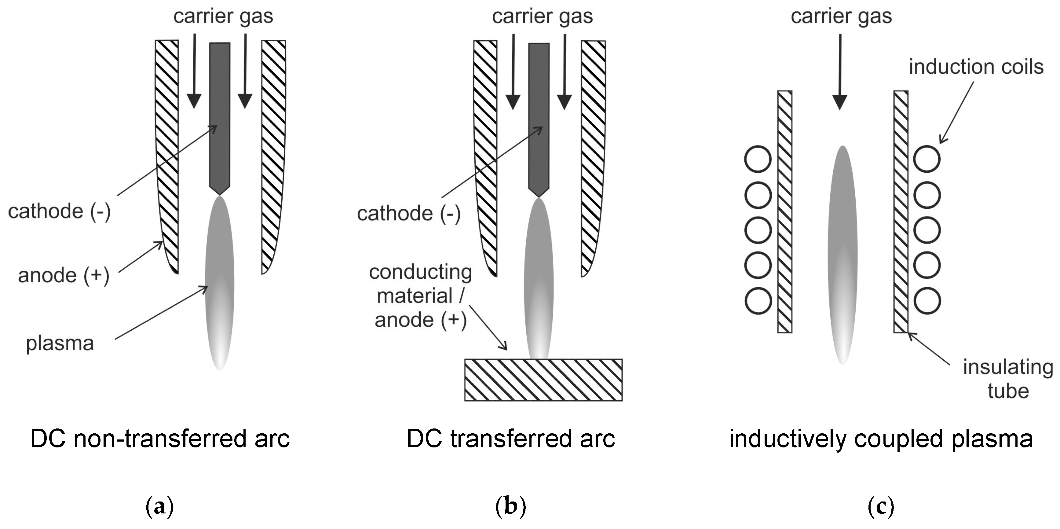
100]. Usually, thermal plasmas are employed for these plasma treatment applications. Arc-generated plasmas are mainly used, for example, as a transferred arc configuration (see also
Figure 5).
This transferred arc configuration is only suitable for conductive reactants as one electrode is usually the material to be treated. This means that the waste material is exposed to the arc plasma [
63]. The transferred arc plasma typically has peak temperatures of 12,000 to over 20,000 K. It provides a very wide range of power between a few hundred watts to tens of megawatts [
63]. In the non-transferred arc plasma, the two electrodes do not participate in the process. They have the sole function of plasma generation. In this configuration, the arc is contained inside a water-cooled plasma torch. The exiting plasma jet with peak temperatures of 10,000–14,000 K is used for processing of the waste material. As the plasma decays outside the torch, the treated material is usually not exposed to these high temperatures [
101].
The plasma treatment enables a significant purification of gas as the production of tars is reduced. This is due to the reactive species produced by the plasma (e.g., atomic oxygen and hydrogen or hydroxyl radicals, as described above). This enhances strongly the degradation of tars with much higher efficiency than conventional processes. Furthermore, a synthesis gas is produced that is enriched with hydrogen (during water–gas shift reaction) [
95]. The ability to be operated at high temperature can allow synthesizing or degrading chemicals, which cannot be realized by conventional combustion. This can accelerate the chemical reactions largely. The application of plasma allows a simple enthalpy control by adjusting the electrical power [
95].
In the context of waste treatment, chemical degradation of thermoplastics (which is also called tertiary or chemical recycling) also becomes an important aspect that facilitates the production of liquid fuels and chemicals [
102]. One of these tertiary recycling methods is pyrolysis, which can be thermal or catalytical. The thermal pyrolysis requires high temperatures, which often can lead to products with low quality, i.e., low molecular weight substances. Catalysts reduce the temperature and reaction time. This allows for the production of hydrocarbons with a higher added value, e.g., fuel oils and petrochemical feedstocks. Thermal plasmas can be used as well for diesel fuel production from thermoplastics (see, e.g., Gabbar et al. [
103]). A DC non-transferred low thermal plasma (270 W) was used in the range of 625 °C to 860 °C for conversion of low-density polyethylene (LDPE) into diesel oil [
103]. This work was conducted in a lab-scale pyrolysis reactor. The pyrolysis oil sample contained butyl-benzene as a major product. Furthermore, small traces of decane were included in the diesel-range oil.
Zhang et al. [
102] applied a 1000 W microwave cavity and ZSM-5 as a catalyst for production of a large amount of gasoline-range hydrocarbons (74.7–88.5%) from LDPE. The packed-bed catalysis integrated with microwave pyrolysis lead to the formation of syngas at temperature of 450 °C. This mainly consisted of ethylene, ethane, and small quantities of hydrogen and methane. The formation of mono-ring aromatics was distinct at high temperatures and high reactant to catalyst ratios. High temperatures and low ratios lead to more undesirable polycyclic hydrocarbons.
3.3.3. Plasma Pyrolysis and Gasification of Biomass
Biomass pyrolysis and gasification using plasma is a relatively new technique and only few laboratory investigations using biomass feedstock have been reported in the literature [
104,
105,
106]. In comparison to coal, biomass has a large H/C ratio, a higher volatile content and a low ash content which favors a better product yield from plasma pyrolysis [
104]. A small laboratory-scale argon/hydrogen thermal plasma reactor was investigated in Ref. [
104] for biomass pyrolysis of wood sawdust and rice husk. A DC arc discharge at a power of 40.5 kW was applied to generate an argon/hydrogen plasma jet. The biomass injector is located below the plasma for addition of biomass powders using argon as carrier. A maximum carbon conversion of 79% and a maximum oxygen conversion of 72% were reported, which are higher than literature data of coal conversion (see, e.g., [
93]). The gas composition from the plasma pyrolysis of biomass is also very different compared to ordinary low-temperature pyrolysis. The plasma reactor showed higher CO and C
2H
2 content but lower amounts of CH
4 and CO
2, and there is no generation of heavy tar compounds. It is mentioned that the gaseous fuel produced by plasma pyrolysis of biomass may be suitable for syngas applications such as methanol synthesis or for ore reduction in the iron and steel industry. Usage in fuel cells is possible after cleaning and processing of the gas.
Besides many applications using thermal plasmas (see, e.g., [
99,
104,
107]), there are only a few studies on non-thermal plasma application for biomass pyrolysis and gasification [
105,
108]. In Ref. [
105], a non-thermal arc plasma was applied for gasification of crushed corn cob at a discharge power of 25.2 W. The gas yield could reach 79% of the biomass feed without drying when nitrogen was used as carrier gas. The carbon conversion rate was 82.9% and the CO selectivity was 39.9%. A ratio of H
2/CO greater than 1.5 was obtained. It is found that usage of air as carrier gas is beneficial for higher gas yield and CO selectivity. Furthermore, the presence of moisture is advantageous for increased gas yield (especially for production of hydrogen). This also leads to high carbon conversion rate and H
2/CO molar ratio.
However, the use of air as gasifying agent leads to a high amount of nitrogen in the product gas that significantly lowers the heating value. Diaz et al. [
108] applied a DC electrical arc discharge (15–25 kW) to perform a steam plasma biomass gasification process with a high content of hydrogen in the product gas. Hydrogen fractions between 52 mol % and 77 mol % were achieved for different types of biomass studied (hard wood shavings, almond hulls, grape pomace, ground coffee, etc.). The conversion rates ranged between 45.8% and 66.1%. Recent work on plasma gasification of biomass can be found in Ref. [
106] which is also part of this special issue.
4. Electrosprays
The generation of micrometer- and nanometer-size droplets and particles with a narrow size distribution are necessary for many technical processes. For this purpose, electrosprays can be utilized that already have a broad range of applications. For example, they are applied for production of monodisperse micro- and nanoparticles with either simple or core-shell structure (micro- and nano-capsules, coaxial nanofibers, and hollow nanofibers) [
109], for liquid fuel injection, which is applied in micro-combustors of micro-power generators (see, e.g., [
110]), and for emulsion production [
109]. Further important applications are the generation of ions for mass spectrometry [
111,
112,
113,
114] (see also
Section 5) and electrosprays for cooling [
115], as well as spray painting, micro- and nano-film deposition, thrusters for small spacecraft, air purification and agricultural sprays [
113].
One major feature of an electrospray is the ability to produce extremely small droplets and even mono-dispersed sprays. Therefore, there are numerous investigations on various aspects of the operation of electrosprays and their operating modes (see, e.g., the review of Cloupeau and Prunet-Foch [
116]). These modes include e.g., dripping, spindle, cone-jet, and multi-jet [
116,
117]. In the cone jet mode, a conical liquid meniscus is formed at the tip of the electrospray nozzle. It emits a charged jet from its apex (see, e.g., the pioneering work of Zeleny [
118]). For electrosprays, the electric field itself causes the spraying of a liquid in fine droplets. (In other configurations, the liquid is sprayed by pneumatic or other means. Thus, the electric field is only necessary for charging of the drops and for a slight decrease of their average size [
116]). The atomization occurs through the Coulombic interaction of charges on the liquid and the applied electric field, i.e., the primary atomization force remains electrical. This interaction leads to acceleration of the liquid and subsequent breakup into droplets and the buildup of a space charge [
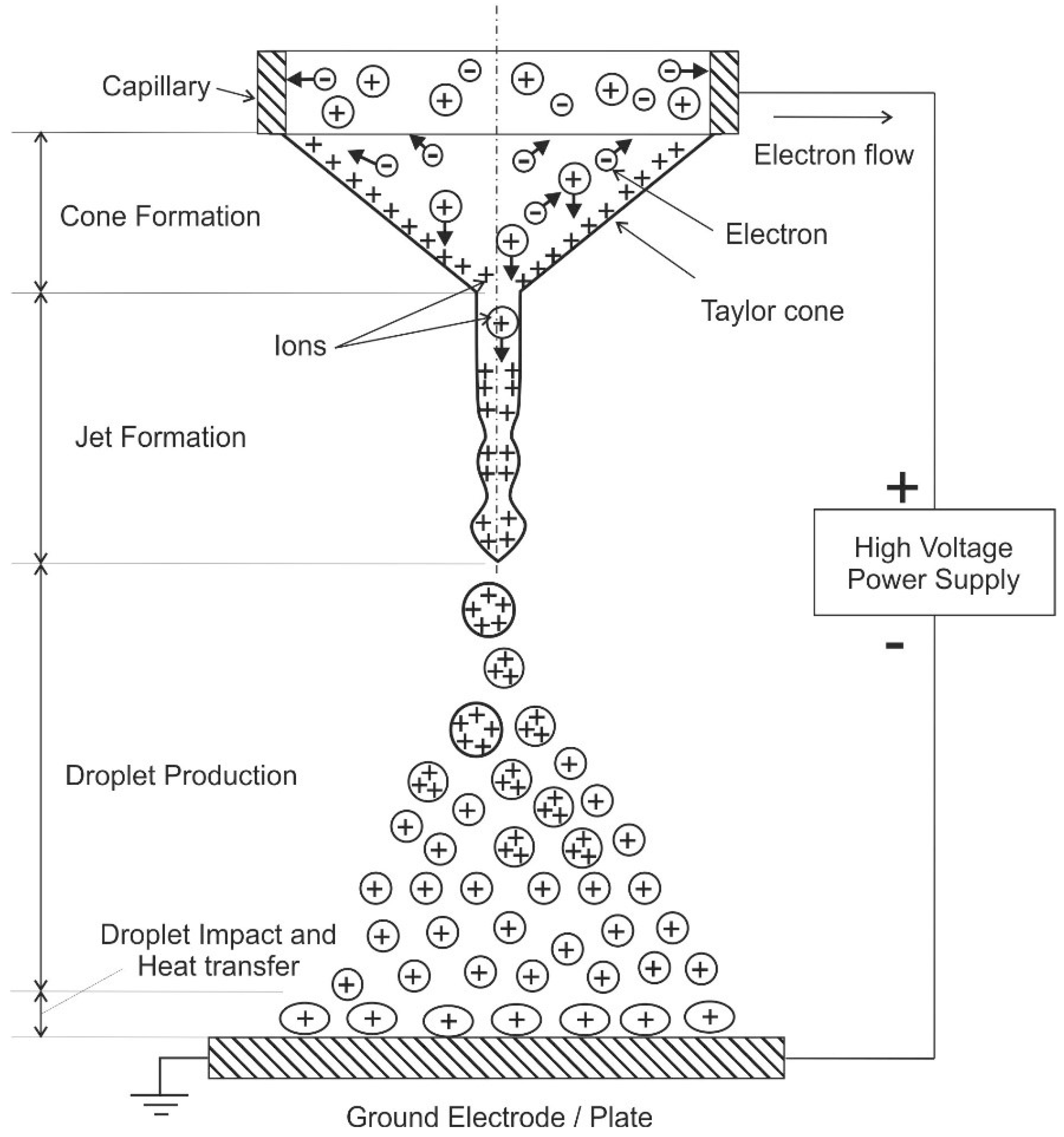
117]. The charged droplets are driven by the potential difference that exists between the nozzle and grounded electrode (plate). Coulombic repulsion of the charged droplets leads to self-spray dispersion and prevents droplet coalescence. A schematic of the electrospray process is shown in
Figure 6.
Electro spraying is usually conducted in ambient air or vacuum. In the cone-jet regime, the “Taylor cone” and a jet is formed leading to continuous production of droplets after applying a potential difference of several 1000 V between the capillary and the ground electrode. This jet breaks into fine charged droplets forming a conical cloud because of repulsion among the droplets [
112]. Afterwards, these droplets may interact with a wall (see
Figure 6, that is utilized e.g., for cooling purposes, see below). Otherwise, evaporation of the charged droplets occurs and formation of the gas-phase ions, which is a fundamental mechanism in mass spectroscopy [
114]. For some applications, the produced charged droplets may be neutralized by different methods, such as corona discharge, additional electrosprays with different polarity, a hot wire or a flame [
119]. The droplet size depends on the electro-hydrodynamic conditions and the liquid properties. Important liquid properties are conductivity, surface tension, viscosity, as well as density. An overview of these involved properties is given in Ref. [
117] for various liquids.
The cone-jet mode (with its multi-jet variant) makes it possible to produce the finest droplets and the highest emission frequencies. The average size of the generated droplets in this mode depends on the conductivity of the liquid, the flow rate, the electrode configuration, and the tip of the capillary. The volume median diameter of the generated droplets varies from more than 100 µm to less than 0.1 µm [
119]. A cone-jet is generated at the tip of a micro-hairpin. Droplets of roughly uniform size, e.g., diameter of 5 µm at a frequency of 200,000 s
−1 can be produced for application of an alternating voltage of a few hundred volts to the capillary [
119].
The droplet size and spatial distribution determines evaporation and wall impingement with associated heat transfer, which is an effective heat transfer process. Due to these reasons, electrospray-cooling is a viable option for thermal management [
115], e.g., for cooling of micro-electronics [
120]. It should be noted that, for cooling of surfaces, the droplet–wall interactions of charged plate and droplets are different compared to uncharged configurations. This is due to the fact that, for electrically charged micro-droplets, it is possible to avoid the rebound from the surface so that the droplet-cooling capacity can be fully exploited [
120]. In the study of Deng et al. [
120], the average size of the produced charged ethanol droplets was 25 µm with a standard variation of 10%. The droplet size can be fine-tuned by adjusting the electrical conductivity of the liquid. This is done by doping ethanol with an ionic liquid (1-ethyl-3-methylimidazolium ethylsulfat, 1.6 ppm by weight) leading to a 25% higher heat flux removal from the wall compared to the un-doped case. The resulting heat flux removed was 96 W/cm
2 for the highest flow rate (1666.7 µL/min) with a cooling efficiency reaching 97%. Further investigations on heat transfer characteristics of cone-jet electrosprays can be found in a recently published paper by Gibbons and Robinson [
115].
In Ref. [
121], spray pyrolysis based on electrosprays in the cone-jet mode is developed for metal oxide nanoparticle synthesis. The electrospray was coupled to an electric furnace to synthesize nanoparticles. The electrospray was neutralized by an additional electrospray of opposite polarity. This reduces the expansion of the cloud of otherwise homo-polarly charged droplets, which could lead to deposits on the reactor wall. The additional electrospray serves also for particle functionalization via electrostatically driven droplet-droplet collisions, which supports mixing of different liquid immiscible and/or incompatible precursors. This enables the coating of the particles and the production of solid and hollow particles.


