Article

Permanent Magnet Brushless DC Motor and Mechanical Structure Design for the Electric Impact Wrench System

Department of Electrical Engineering and Computer Science, University of Central Florida, Orlando, FL 32816, USA
*
Authors to whom correspondence should be addressed.
Current Address: 4000 Central Florida Blvd, Orlando, FL 32816, USA.
Energies 2018, 11(6), 1360; https://doi.org/10.3390/en11061360
Submission received: 29 April 2018 / Revised: 22 May 2018 / Accepted: 24 May 2018 / Published: 27 May 2018

Abstract

:
This paper presents an analytical method to design an interior permanent magnet brushless DC electric motor (IPMBLDC motor) for a kind of electric impact wrench used for loading and unloading car bolts. It takes into account magnet assembly gap, rotor saturation webs, and bridges. Assumed flux leakage coefficient and selected working point of a permanent magnet were used in the initial design. An advanced equivalent magnetic circuit was developed to verify the total flux leakage and the quiescent operating point based on initial design parameters. Key design method points are considered and analyzed. Thermal analysis is given to simulate the temperature rise of all parts of the motor. The new impact wrench mechanical structure is designed, and its working principle analyzed. An electromagnetic field analysis based on MATLAB and the MAXWELL 2D finite element method (FEM) were used in the design to verify the equivalent magnetic circuit and optimize the IPMBLDC motor parameters. Experimental results are obtained to verify the design. The electrical and mechanical designs are combined and an analytical IPMBLDC motor design method is provided. We also show an innovative and reasonable mechanical dynamical calculation method for the impact wrench system, which can be used in whole system design of other functional electric tools.

1. Introduction

Brushless dc motors are popular in a wide range of industrial applications, such as computer peripherals, servo control systems and electrical tools due to their robustness, simplicity, large torque to volume ratio and high-efficiency [1,2,3,4,5,6,7,8,9]. Interior permanent magnet brushless DC (IPMBLDC ) electric motor [10,11,12,13,14,15,16,17] is an important category of these motors, constructed with the permanent magnets inserted into the steel rotor core and does not need to be glued such as in surface mounted permanent magnet motors. The leakage path of interior magnet motors usually includes a saturable magnetic bridge and the web, which will make the coefficient of flux leakage variable. Some studies [18,19,20,21,22,23,24,25,26,27] have been done on Brushless direct current motor (BLDC) design for different applications at different power levels. However, most of them used the computer-aided tools and experience to get the BLDC motor parameters, which usually takes time. In this paper, we are going to introduce a quantitative model to obtain the initial BLDC motor parameters. Then the MAXWELL 2D finite element method (FEM) is used to optimize all the initial design parameters, which will give guidance for the BLDC motor design and reduce the design time. The electric impact wrench motor application is different from the regular applications that incorporate motors working with a continuous model. The impact wrench motor works with a discontinuous model, which requires high reliability, small size, less bolting time, low cost, high pull-out torque to load and unload car bolts in a short time and to enable industrial mass production. In this paper, a much lower torque angle is selected at the rated power and speed in the design. Such a design can effectively increase the overload handling capability and provide high torque at a short time.
This paper presents an analytical method to design the interior permanent magnet brushless DC motor with concentrated windings black and applied in the impact wrench. The assumed flux leakage coefficient and working point of a selected permanent magnet are used in the initial design. The equivalent magnetic circuit of IPMBLDC motor is built to calculate the coefficient of flux and working point of a permanent magnet based on the design output parameters. A computer-aided tool is used to calculate and compare the calculated values and hypothesis values. Structure parameters will be adjusted based on the error between the assumed and the calculated value. A new mechanical structure of the impact wrench is designed, and its working principle is analyzed in detail. The motor connects to a planetary gear reducer with a transmission ratio to get high output torque; hence, the speed of impact wrench will be reduced. The bolting time is related to motor speed, main pressure spring as well as shock block. The motor is required to get high load capability and improve lifetime. The new impact wrench mechanical structure is simple, has a small volume, and is lightweight and easy to use. It can substantially reduce labor intensity and improve work efficiency.
Maxwell 2D FEM is used to verify the equivalent magnetic circuit and optimize the design of the IPMBLDC motor. Thermal analysis is carried out with the aid of MotorSolve packages. The working principle, the planetary gear reduce transmission ratio formula as well as the dynamic model of the main pressure spring and shock block in the impact process is introduced. The whole electric impact wrench has been designed and fabricated. Experiment results are obtained to verify the design.
This paper is organized in the following sections: Section 2 focuses on the motor design process. Section 3 then looks at the impact wrench mechanical system design and calculation. Section 4 and Section 5 proceeds to show associated simulation analysis as well as experimental results. Finally, the conclusion and remarks are given in Section 6.

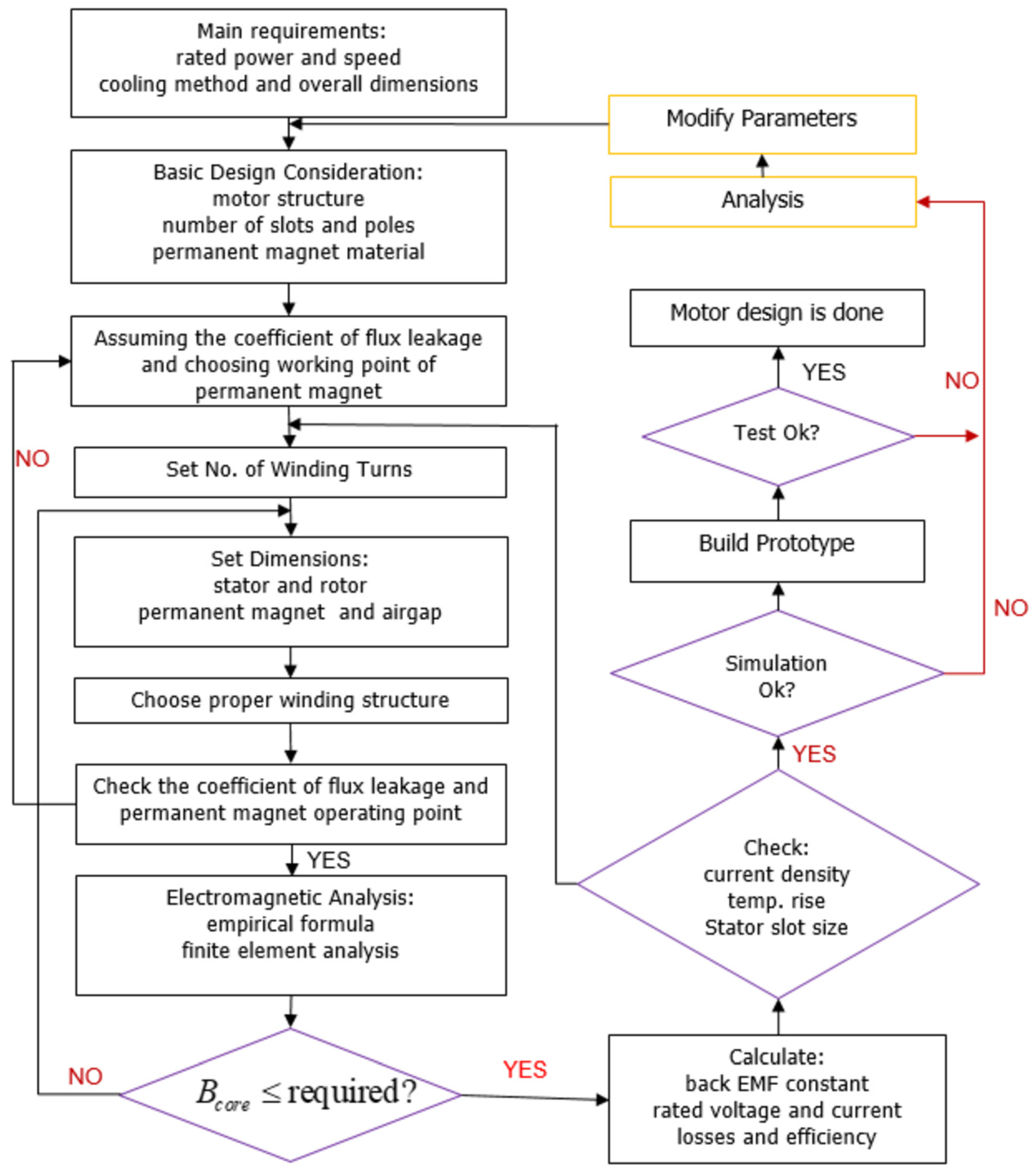
2. Motor Design Process

The design process of IPMBLDC motor is more complicated compared to the surface permanent magnet motor. The leakage path of IPMBLDC motor usually includes saturable magnetic bridges and webs. These bridges and webs are designed to provide integrity to the rotor. These bridges and webs introduce magnetic short circuits and complicate the design and analysis of the IPMBLDC motor. The coefficient of flux leakage k l s varies because of saturable magnetic bridges and webs. Figure 1 shows the whole design process. An assumed coefficient of the flux leakage k l s and a selected working point of the permanent magnet α m are used for the initial design of IPMBLDC motor. The value of the coefficient of flux leakage k l s and the working point of permanent magnet α m will be calculated after the rough parameters are determined based on our equivalent magnetic circuits model. Structural parameters will be adjusted using computer-aided tools based on errors. Repeated calculations will be done with the aid of Matlab. We provide the initial IPMBLDC motor parameters design size mathematical model, and a much smaller torque angle than that in traditional designs at rated load and thus has higher overloading handing capability and improved efficiency. After that, electromagnetic analysis and FEM simulation can be performed to optimize the design parameters. The permanent magnets should not be demagnetized in all loading situations. This IPMBLDC motor only works around 1 s every time. The motor’s speed depends on how much torque is needed to load and unload the bolts. For this application, only speed loop control is enough.

2.1. IPMBLDC motor Structure Consideration

2.1.1. Control Type

There are two classes of brushless permanent magnet (PM) motors control: ac and dc. The design requirements are different, which is related to the back-EMF waveform and the rotor-position sensing. The motor of the electric impact wrench should be able to tolerate some torque ripple and does not require extra field weakening at higher speeds. Based on these requirements, dc control driven by an inverter is selected for the IPMBLDC motor design. The detailed modeling of such a machine-inverter system has been investigated well in [28,29]. We designed and fabricated a hall sensor board (Figure 2) to detect the correct current switching position. IPMBLDC motor motor is considered where the inverter operates using the 120 commutation method [28]. The IPMBLDC motor is designed for electric impact wrench used for loading and unloading car bolts, which will work using a discontinuous model. There are less requirements for IPMBLDC motor control design, but high requirements for IPMBLDC motor design. Only the speed loop control is enough for this special application. The harmonics of air-gap flux and back EMF is high because of the hall sensor board and only speed loop control. In some advanced applications such as fixed torque electrical tool, the current loop is required to be added, the encoder or resolver must be used to replace the hall sensor board, and the advanced control method must be applied; this will result in significantly fewer harmonics, but will make the whole system much more expensive.

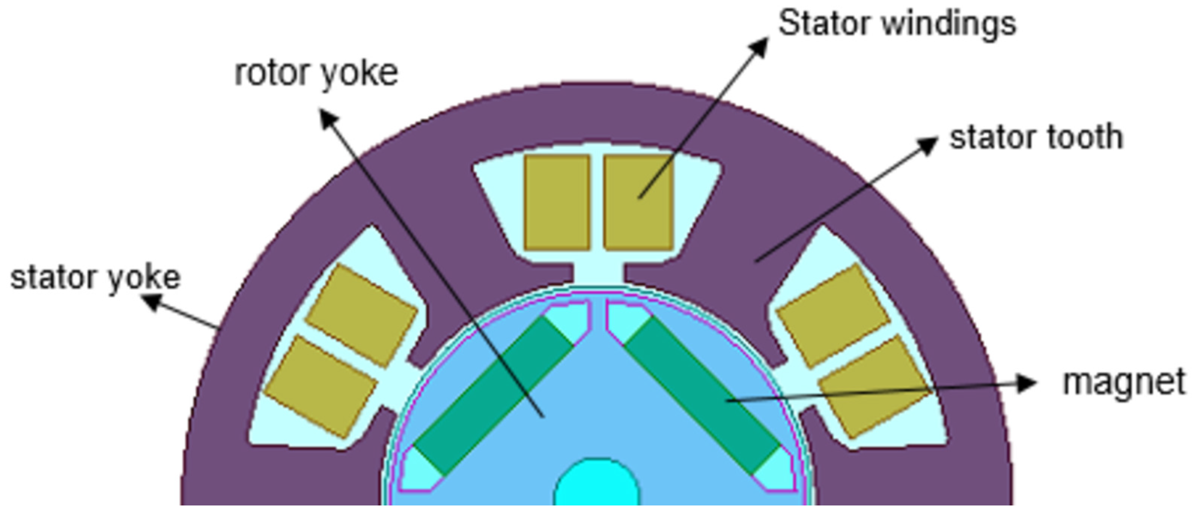
2.1.2. Motor Structure

Motor structure is very important for the PM motor design. Different types of Brushless Permanent Magnet Machines have different characteristics as discussed in [30]. In this paper, the IPM rotor structure is chosen to be the traditional straight type. The surface-magnet machine is not suitable for high speed; V-type and Spoke-type cost more and are harder to fabricate compared to the traditional straight type motor. Traditional straight type can satisfy all the requirements of the electric impact wrench.

2.1.3. Permanent Magnet Material

NdFeB and SmCo are widely used in the PM motors. SmCo has a wide temperature range and is used in the machines that need to work at high temperatures. The electric impact wrench motor does not need a wide temperature range, so NdFeB is chosen to get a higher power density.

2.2. Preliminary Stator Sizing

We should consider the preliminary stator size first, which is the foundation of the whole design. It will affect the other parameters of the motor. The following equation can be used to determine the stator bore diameter and length.
D 2 l i T m = ϖ 0 ,
where D is stator bore diameter, l i is stator core length, T m is related mechanical torque, and its value is determined by the rotor rotational speed ω and the required output power P o u t . ϖ 0 is a coefficient, which is related to the cooling methods. Typically, the value of ϖ 0 is around 0.5925–0.8295 m 2 /kg for 10 hp output power or less when air cool method is selected; the value of ϖ 0 is around 0.237–0.5925 m 2 /kg for 10 hp output power or less when the water or other liquid cooling methods are selected. The motor size will be smaller when the better cooling method is used. Otherwise, a larger size is required for adequate heat dissipation. In our IPMBLDC motor design, the fan cooling method with ϖ 0 = 0.8295 m 2 /kg is selected as the cooling method reference.

2.3. Stator Core Design

Figure 3 shows the flattened view of a motor, which indicates that the total flux through the yoke is equal to the flux in the air gap via a half pole pitch. Therefore, the flux can be calculated in the core by integrating the air-gap flux density
Φ c o r e = Φ g a p , p e r   h a l f   p o l e   p i t c h = l e 0 π / P B g ( θ a ) D 2 d θ a = D 2 l e 2 P 0 π / P B g , p k cos ( θ a e ) d θ a e D P l e f f B g , p k ,
where l e stator effective length including fringing due to ducts, P is the number of poles, θ a is phase a reference angle, and θ a e = P 2 θ a . The core flux density can be calculated as:
B c o r e , p k = Φ c o r e d c k i l i = D B g , p k l e P d c k i l i ,
where d c is yoke thickness, k i takes into account the insulation space between the laminations, l i is stator core length (not including air ducts and fringing), B g , p e a k is air-gap flux density and l e is stator effective length including fringing due to ducts. We define slot pitch τ s as:
τ s = π D S
The slot pitch is much smaller than pole pitch, assuming the flux density of one stator tooth is constant. The flux through one stator tooth is gained by integrating the air gap flux density over the whole slot pitch. Its value is approximately equal to the peak flux density, neglecting the small value difference between l e and k i l i .
Φ t o o t h B g , p k τ s l e .
We can obtain the back iron and the tooth flux density relationship after some derivations
B c o r e , p k B t o o t h = D t s P d c τ s ,
where t s is tooth width. If selecting t s = 0.5 τ s and B c o r e , p k = 0.8 B t o o t h , the yoke thickness can be expressed.
d c = D 1.6 P .
This equation has physical meaning; if the larger number of poles is picked up in the design, yoke thickness will be smaller, and it is not necessary to use that much yoke thickness to finish the design.

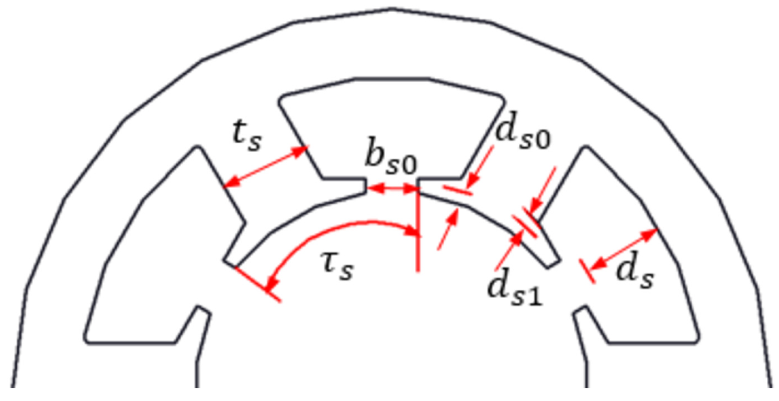
2.4. Stator Slot and Winding Design

Typically, the experienced equations are used to determine the stator slots’ size. We can see the schematic structural view of the stator slots from Figure 4.
0.4 τ s t s 0.6 τ s 3 t s d s 7 t s b s 0 ( 0.1 0.5 ) b s d s 0 ( 0.1 0.5 ) b s d s 1 ( 0.1 0.5 ) b s
where b s = τ s t s . We use the following equation to determine the rated phase voltage
V Φ , r a t e d = 2 π f e N ^ a Φ g , p k 4.44 f e N ^ a Φ g , p k ,
where f e is electrical frequency, Φ g , p k = 2 B g , p k D l i P is the peak flux of air-gap, N ^ a = k w N a / k l s is the effective number of series turns per phase, k w is winding factor, and number of series turns per phase N a = P q N c / C . If the number of parallel circuits of armature winding C = 1 , then N a = P q N c . We add assumed coefficient k l s to compensate for the leakage flux. Finally, the number of turns per coil can be expressed as
N c = k l s V ϕ , r a t e d C 2 2 π f e q k w B g , p k D l i .
The phase current can be determined regarding current density and slot parameters as
I p , r a t e d = d s π D r s 2 N c N s J s
where J s is the current density, N s is the number of slots, r s is the ratio of slot width and slot pitch, and d s is the slot pitch. We can use the current density equation to choose reasonable slot dimensions. It also provides some restriction of motor design, which is determined by cooling condition and thermal conductivity. The input power is related to phase voltage and phase current of the motor, which can be calculated as
P i n = 3 V ϕ , r a t e d I p , r a t e d cos θ .

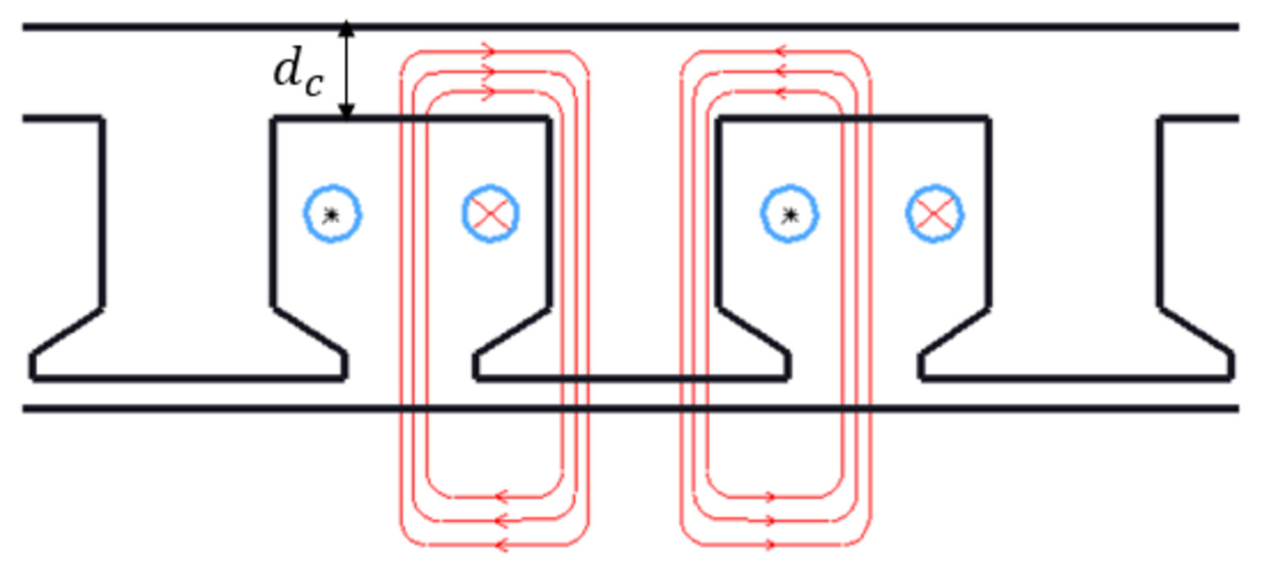
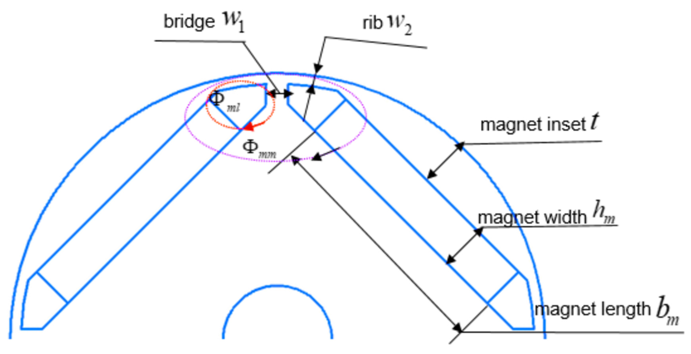
2.5. Magnetic Bridge and Rib

The magnetic bridge (Figure 5) affects the leakage coefficient of the interior permanent magnet motor [31] as shown in (13). Flux density around the magnetic bridge is very high, which results in low permeability and high reluctance, thus magnetic flux leakage is small. If stronger magnetism isolating effect needs to be obtained, the size of the magnetic bridge should be smaller, but the mechanical strength will be reduced when the motor runs at high speed. Comprehensive consideration should be taken when choosing the size of the magnetic bridge.
Φ 0 = α m B r A m k l s
where Φ 0 is no-load main flux, k l s is leakage coefficient, α m is working point of a permanent magnet, B r is residual magnetization density and A m is cross-sectional area providing the magnetic flux per pole.

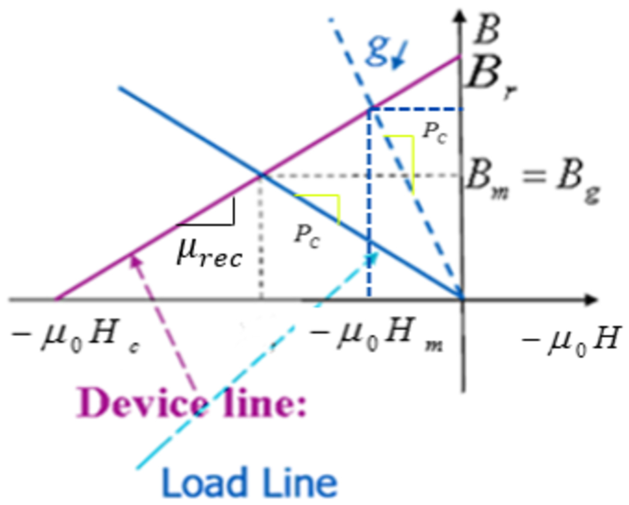
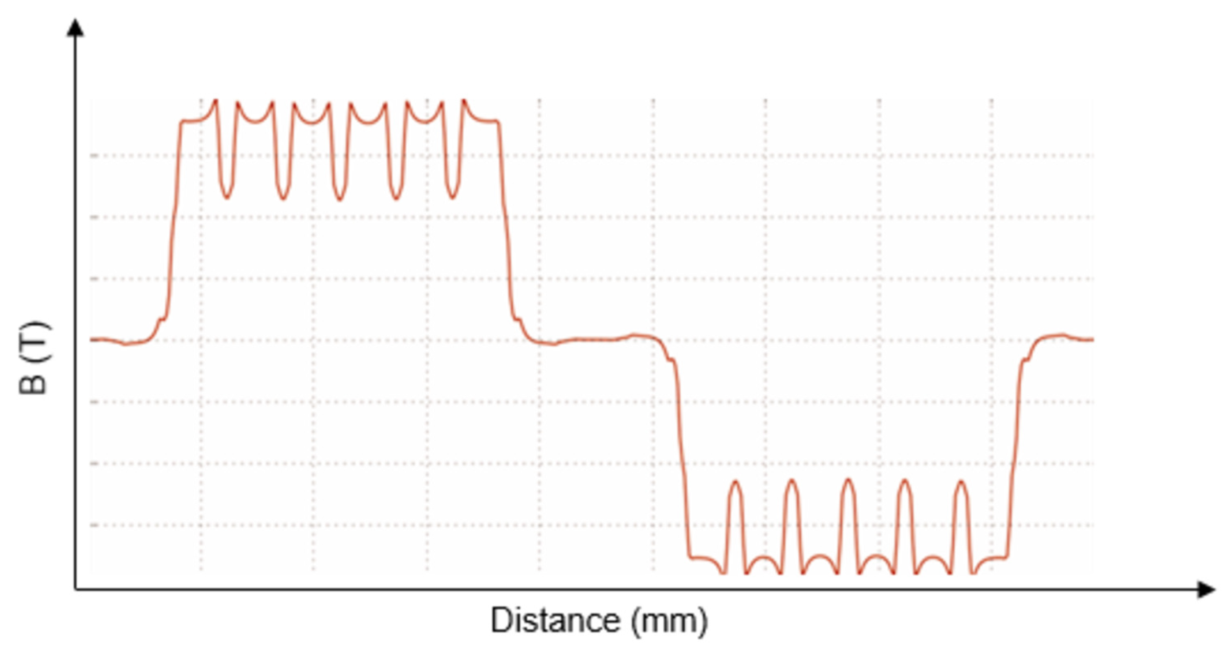
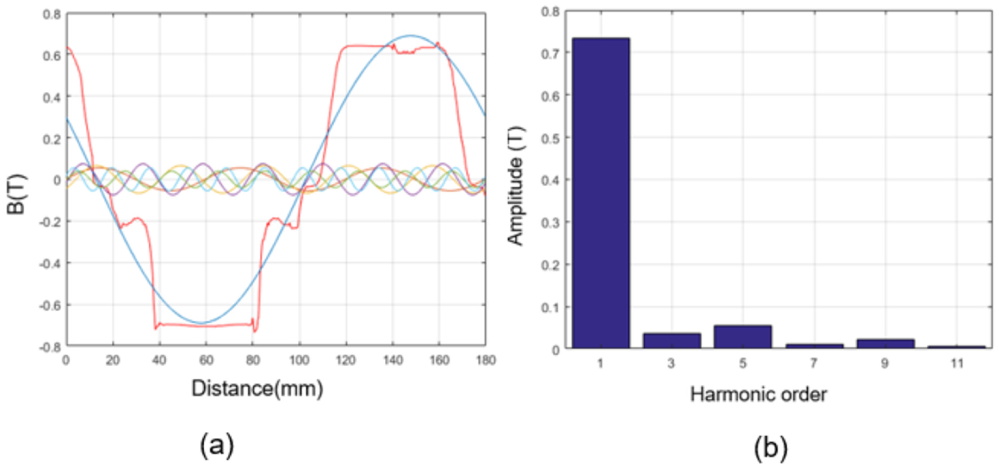
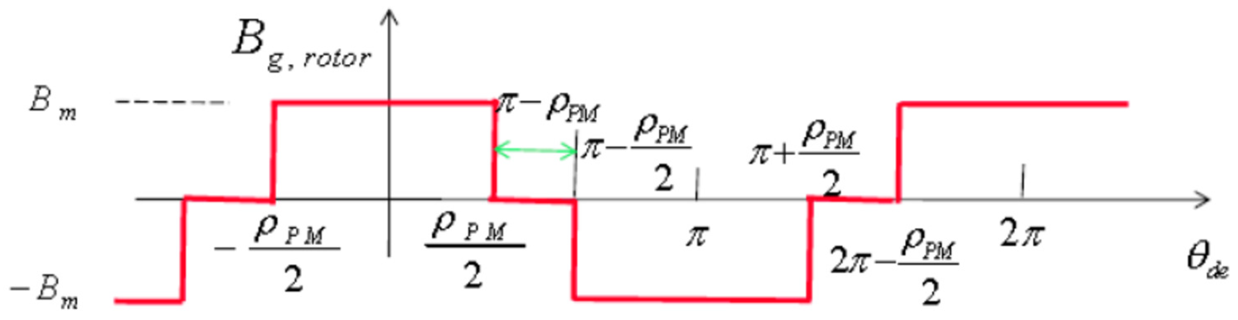
2.6. Working Point of a Permanent Magnet and Air Gap Size

The working point of a permanent magnet is related to the energy of the motor. Figure 6 shows the B-H curve of a permanent magnet material. B r is the remanent flux density, B m is the flux density in the magnet and H m is the magnetizing force in the actual magnet. The values of B r , B m , and H m depend on what kind of magnet materials and working point that kind of magnet has. There are two lines on Figure 6 called the device line and load line. The device line is defined as the theoretical demagnetization cure and the load line is the line through the origin to the working point. The slope of device line is the relative recoil permeability μ r e c , and μ 0 is the permeability of air. Since B m = B r + μ 0 μ r e c H m , the x axis value of the working point can be obtained and this should be μ 0 H m . After some derivation, the load line equation (flux density in the magnet) can be expressed as:
B m = μ 0 d m g A g A m H m = P c ( μ 0 H m ) ,
where P c is called permanence coefficient, which is the slope of the load line and is equal to:
P c = d m g A g A m = A g / g A m / d m .
We define B m = α m B r , H m = ( 1 α m ) H c , where α m is called the working point of a permanent magnet, A g is air-gap area, and A m is cross-sectional area providing the magnetic flux per pole. We can obtain the maximum energy by choosing α m = 0.5 . However, to avoid demagnetization and knee effect, we always choose a working point higher than 0.5. In this design, the working point equal to 0.85 is selected. Now we are going to determine the air-gap magnetic field from the PM rotor. Typically, the shape of IPMBLDC motor air-gap magnetic field is shown in Figure 7, and the waveform can be simplified as shown in Figure 8. We define e m as embrace of the permanent magnet. The magnet electrical angle ρ P M is defined on the inside of the magnet towards the center of the machine, and its value provided in electrical degrees is equal to e m π . Its value varies from 0.5 to 1. It affects the air-gap magnetic field, peak flux density of the teeth and yoke, cogging torque, etc. After performing a Fourier series expansion, the air-gap magnetic flux density can be obtained:
B r h = 2 2 π [ ρ P M / 2 ρ P M / 2 B m cos ( h θ a e ) d θ a e + π ρ P M / 2 π + ρ P M / 2 ( B m ) cos ( h θ a e ) d θ a e ] = 4 π sin ( h ρ P M 2 ) h B m ,
where k p h = sin h ρ P M 2 is pitch factor for the h t h harmonic. The peak air-gap magnetic flux density B r , p k can be approximately calculated by:
B r , p k 4 π sin ρ P M 2 B m .
Typically, power factor p f is approximately chosen to be 0.9 at full-load for the IPMBLDC motor design. The power angle θ = a c o s ( p f ) 180 / π . The torque angle δ is usually designed to be in the range of 15–30 degrees. In order to get more power handling capability and pull-out torque, a lower torque angle is selected for the design. The peak value of the net magnetic flux density B g , p k and peak winding magnetic flux density B a , p k are defined:
B g , p k = B r , p k cos ( ( δ θ ) π / 180 ) p f B a , p k = B g , p k ( sin θ π / 180 ) + B r , p k sin ( ( δ θ ) π / 180 ) .
Normally, the air-gap of the IPMBLDC motor is small so the peak winding magnetic flux density can be calculated from:
B a , p e a k = 4 π μ 0 g t o t a l N a ^ P 1.5 2 I p , r a t e d ,
then the effective air-gap size can be calculated based on (19)
g t o t a l = 4 π μ 0 B a , p e a k N a ^ P 1.5 2 I p , r a t e d ,
finally, the air-gap size can be determined from
g = g t o t a l k c ,
where k c is called carter’s coefficient and can be approximately determined by
k c = τ s τ s b s 0 2 5 g t o t a l + b s 0 .

2.7. Size of the Permanent Magnet

When the air-gap size is obtained, (23) and (24) can be used based on [32] to determine the size of the permanent magnet. Assumed flux leakage coefficient and selected permanent magnet working point are used in the equations.
h m = K s K α α m ( 1 α m ) k l s g
b m = 2 k l s B g , p k τ 1 π α m B r K ϕ
where h m is magnet length, b m is magnet width, g is air gap length, K s is motor saturation factor with values ranging from 1.05 to 1.3, K α is rotor structure factor whose value range is between 0.7 and 1.2, B g , p k is peak value of air gap fundamental wave, K ϕ is air gap flux waveform factor, which is related to the pole arc coefficient. The air gap flux waveform of an ideal IPMBLDC motor is a square wave, so the value of pole arc coefficient should be big enough with reference to [32]. For IPMBLDC motor, the pole arc coefficient can be approximately calculated using (24)
α p b τ p
where b is pole shoe arc length, and τ p is pole pitch.

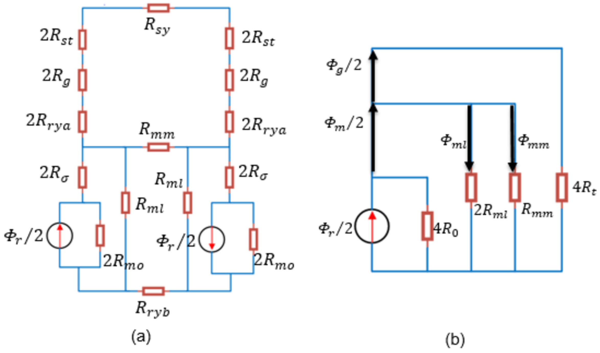
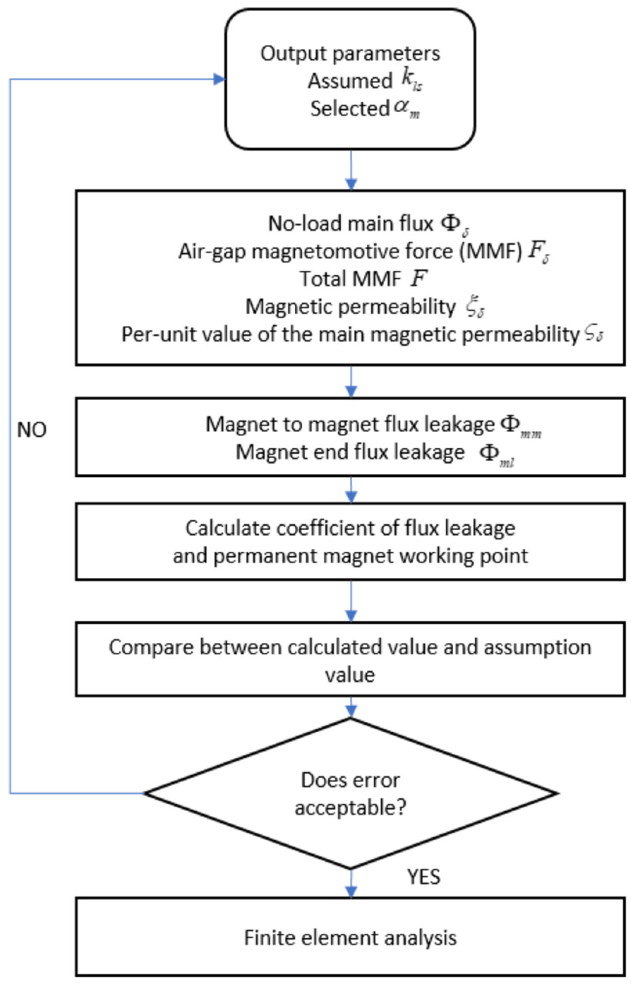
2.8. Improved Magnet Circuit Model of IPMBLDC motor

A commonly used half of IPMBLDC motor configurations is shown in Figure 9.
The route of main flux loop goes through the magnet, rotor yoke, air gap, stator tooth, and stator yoke. Taking the flux linkage of the magnet to magnet and magnet end flux linkage into consideration, the improved equivalent magnetic circuits of IPMBLDC motor, which is composed of a half-pole pair for which the symmetry is considered, as shown in Figure 10a.
Where R s y , R s t , R g , R r y a , R r y b , R σ , R m o , R m l , R m m are the reluctances of stator yoke, stator tooth, air-gap, rotor yoke above the magnet, rotor yoke below the magnet, assembly gap between magnets and laminations, the magnet, the magnet end flux leakage, magnet to magnet flux leakage, respectively.
Figure 10a can be simplified as shown in Figure 10b. R z is the total reluctances of air-gap, stator tooth, rotor tooth, stator yoke, rotor yoke above and below the magnet, which can be calculated as
R z = R s y / 4 + R s t + R g + R r y a + R r y b .
The magnet end flux leakage reluctances can be expressed as
R σ = d σ μ 0 A σ ,
where d σ is the distance between the magnet and the duct, A σ is the cross-sectional area of the air-gap between the magnet and the duct. The magnet reluctances are equal to
R m o = h m μ 0 μ r A m
where h m is the length of the permanent magnet, A m is the cross-sectional area of magnet. R 0 is sum of magnet end flux leakage reluctances and magnet reluctance. Thus,
R 0 = R σ + R m o .
To calculate the rationality of the point of the operation and the coefficient of the flux leakage, it is necessary to analyze the equivalent of the magnet circuit, estimate the main magnetic circuit as shown in the Figure 11, analyze the magnet end flux leakage ϕ m l and the magnet to magnet flux leakage ϕ m l . We assume the bridges and webs are saturated, which can be replaced by a flux-source. We also assume the magnet web flux density is 1.8 Tesla. Therefore, the magnet end flux leakage Φ m i can be obtained. The flux density of the magnet depth can be limited to 2 Tesla. Therefore, the magnet to magnet flux leakage ϕ m m can be calculated. Comparing the calculated total flux leakage value to the value of the assumption, some structural parameters will be adjusted based on errors using computer-aided tools. We do the same to the operating point α m . All these repeated calculations will be done with the aid of Matlab. A flowchart of the procedure of the calculation can be obtained as shown in Figure 11.
Some magnetic circuit calculation equations are listed in Table 1. Some definitions of symbols form the table are listed: α p pole is coefficient, τ p is pole pitch, d σ is distance between the magnet and the duct, A σ is the cross-sectional area of the air-gap between the magnet and the duct, A m is the cross-sectional area of the magnet, R m o is magnet reluctance, τ s is polar distance, F g , F s t are magnetic motive force of air-gap and stator tooth, F s y , F r y are the magnetic motive force of stator yoke and rotor yoke, λ δ is main magnetic permeability, and ξ δ is per-unit value of the main magnetic permeability.

3. The Design and Calculation of Impact Wrench

3.1. Working Principle

An electric impact wrench includes a motor, planetary gear, main pressure spring and shock block. The new mechanical structure makes the planetary gear retarding mechanism as the main transmission mechanism, which can guarantee small volume, lightweight, simple structure, high torque and power, and simple control requirement of IPMBLDC motor. The motor output force is transmitted by the planetary reducer to the mandrel, and then by the ball, driven by the main pressure spring to make the shock block rotate. Shock block uses its two convex claws to impact shock rod. The impact rod drives the bolt through the sleeve under the action of impact force. When the resistance torque of the bolt exceeds the torque transmitted by the main spring to the impact head, the impact head is retracted along the v-groove of the mandrel under the restriction of the ball, resulting in impact shock block and shock rod convex shoulder tripping. The shock block will continue to rotate under the motor driven at this time. The pawl crosses the shoulder and produces an additional angular velocity under the main pressure spring, which pushes the pawl against the shoulder and generates an impact torque. The torque is then passed through the sleeve to the bolt or nut, which will make the bolt or nut rotate by an angle. The cycle of shock will continue until the completion of the bolt loading and unloading works. The mechanical structure is shown in Figure 12.

3.2. Planetary Gear Ration Calculations and Design

Our planetary gear for electrical impact wrench is made of one sun gear, one ring, and three planet gears. The sun gear works as the active part, three planet gears are the followers, and the ring is fixed to the housing. The simple planetary gear mechanism is shown in Figure 13.
According to the theory of machines and mechanisms, it is known:
i 13 H = n 1 H n 3 H = n 1 n H n 3 n H = z 3 z 1
where n 1 , n 2 , n 3 are the speed of sun gear, ring, and plant gear, respectively, z 1 is tooth number of sun gear and z 3 is tooth number of ring.
Since the ring is fixed to the housing, its speed is 0, the planetary gear transmit ratio can be obtained:
i r = i 1 H = n 1 n H = 1 + z 3 z 1 .
After the required planetary gear transmit ratio is known. We can select the tooth number for the sun gear, ring, and plant gear based on (31) for our design.

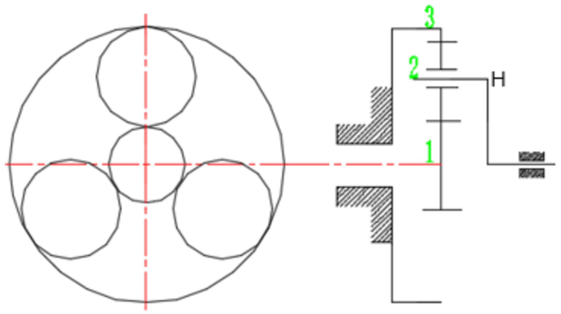
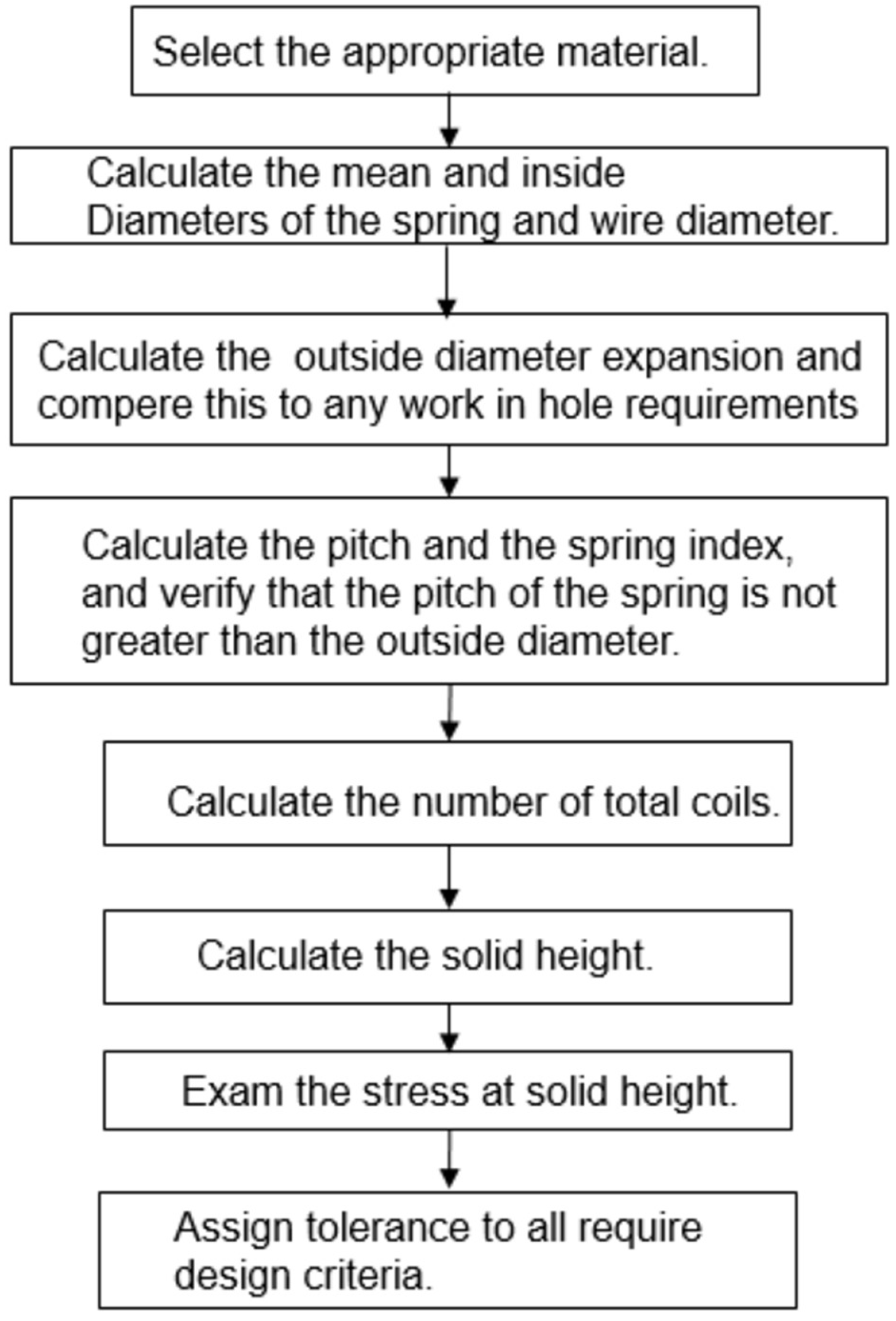
3.3. The Main Compression Spring Design

The main parameters of pressure spring of impact wrench are shown in Table 2. According to dynamic principles, spring index C s = d c D c ; spring constant k = G D c 8 C s 3 N 2 , where D c , d c are out and inner diameter of a spring winding coil and G is shear modulus of elasticity; the minimum load on spring is F 1 = k S 1 ; the maximum load on spring is F 2 = k S 2 ; the average load on spring is F a = ( F 1 + F 2 ) / 2 ; the resistance torque of the spring to the mandrel M F = F a r o tan β , where r o is ball to spindle center distance and β is the angle of spiral. For our electric impact wrench, it is required to make sure the torque from the motor to the mandrel is less than the resistance torque of the spring to the mandrel; this is the special requirement for our design. We can follow the mechanical design handbooks to do the compression spring design step by step, so the detailed procedures are not going to be introduced. The basic design process is shown in Figure 14.

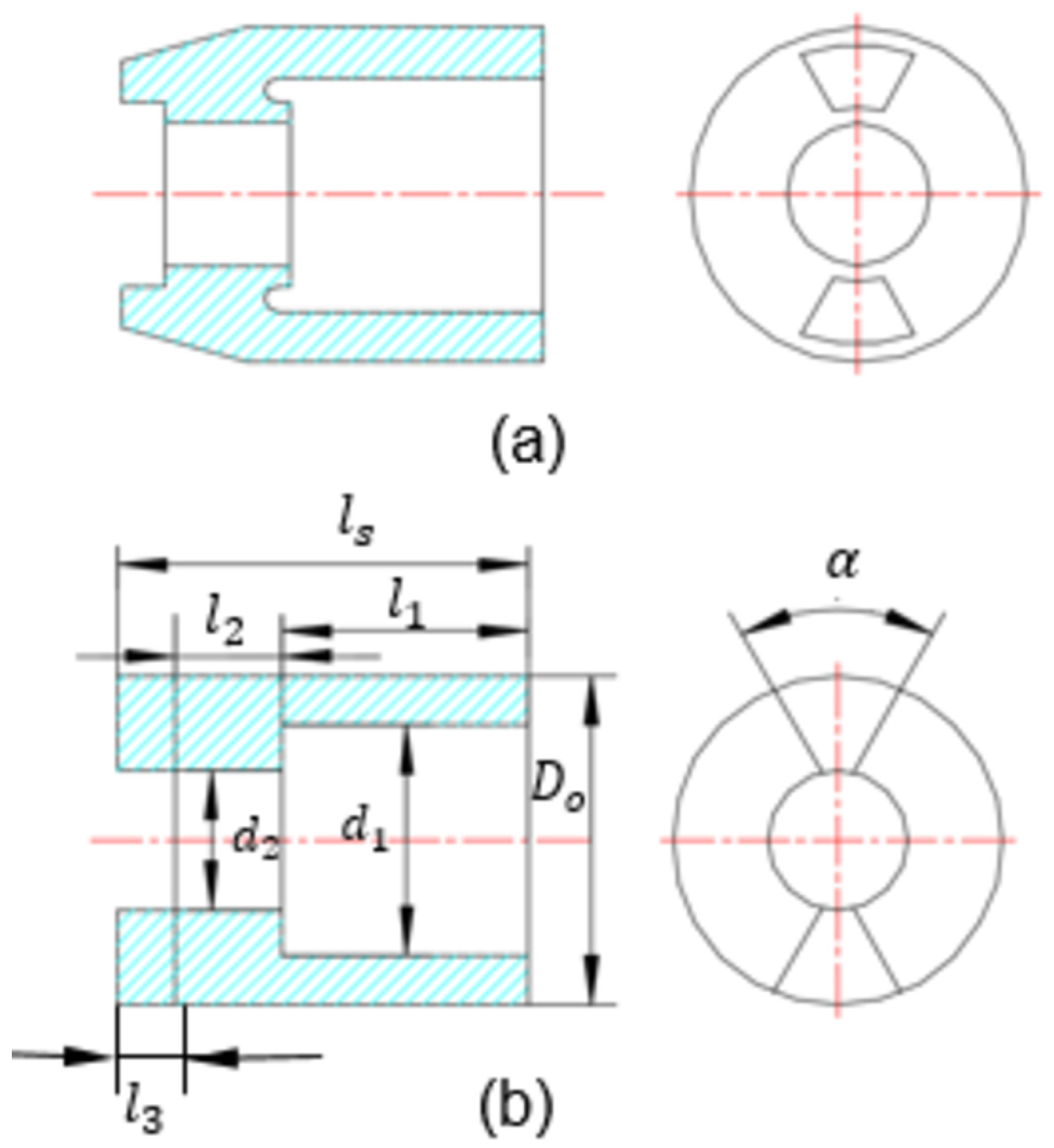
3.4. Shock Block Dynamic Calculation and Design

The shock block shape is shown in Figure 15a. Some experience equations are listed below.
l 1 ( 1 2.5 ) l 2 l 3 ( 0.3 0.5 ) l s d 1 ( 1.2 1.5 ) d 2 D o ( 1.2 1.5 ) d 1
For convenient calculations, it is simplified to two steel tubes and two fan-shape claws as shown in Figure 15b.
The shock block quality is
m = p π l 1 ( D o 2 d 1 2 ) 4 + p π l 2 ( D o 2 d 2 2 ) 4 + α p π ( D o 2 d 2 2 ) ( l s l 1 l 2 ) 180 × 4
When it is rotating, the steel tube is like the hollow cylinder rotating around the rotation center. The fan-shaped claw is equivalent to a symmetrical fan rotating around the rotation center. We can obtain the moment of inertia of the shock block based on the theory of machines and mechanisms
J = m 1 + m 2 + m 3 8 D o 2 + m 1 8 d 1 2 + m 2 8 d 2 2 + m 2 8 d 3 2 ,
where m 1 or m 2 is one of the two different steel tubes quality, and m 3 is two fan-shape claws quality.
The absolute angular velocity of the shock block before the impact consists of the average angular velocity of the mandrel and the additional angular velocity of the shock block, that is ω 0 = ω t + ω a . The average angular velocity of the mandrel ω t = 2 π n / ( 60 i ) . The output power of the IPMBLDC motor is stored in the form of a compressing spring. The stored energy by the compression spring releases into two parts. One part is converted to the kinetic energy of the downward moment of the shock block, and the other part is converted to the kinetic energy of the shock block rotation. According to energy conservation law:
F a h = J ω a 2 2 + m ( J r tan β ) 2 2
after some derivations, the additional angular velocity of the shock block can be obtained:
ω a = 2 F m h J + m ( r tan β ) 2 .
We performed the design based on the desired value ω a . After picking up coefficients for each part of length and diameter according to (32), we put (33) and (34) to (36). Matlab will numerically calculate the relationship between D o and l s . Normally, D o value is selected according to our IPMBLDC motor housing diameter; than we can use the relationship between D o and l s to get the value of l s . Finally, the values of the all parameters can be obtained.
Impacting shock rod, sleeve, and bolts, in essence, is an elastic collision process of shock block around the rotating center. During the elastic collision, the energy will be transferred. The efficiency of energy transmission is
η = Δ E 1 E 1 ,
where Δ E 1 is the energy difference before and after impact, E 1 is energy before impact. Assuming the collision is elastic, the recovery coefficient is 1. According to collision theory, it can obtained:
η = 4 J J J + J 2 = 4 a 1 + a 2
where J is the converted inertia of the impact system, a = J / J . In the process of disassembly of bolts, J changes all the time. Therefore, a is also variable. Assuming the change range from a 1 to a 2 , then the average theory impact efficiency can be obtained. In our design, the range of a is from 0 to 18.
η ^ = a 1 a 2 4 a ( a + 1 ) 2 d a a 2 a 1
Finally, it can be determined by:
η ^ = 4 [ 1 a 2 a 1 ln a 2 + 1 a 1 + 1 1 ( a 1 + 1 ) ( a 2 + 1 ) ] .
If the required tightening torque is T , the time of tightening a bolt can be obtained t b = T / E η ^ .

4. Performance Analysis

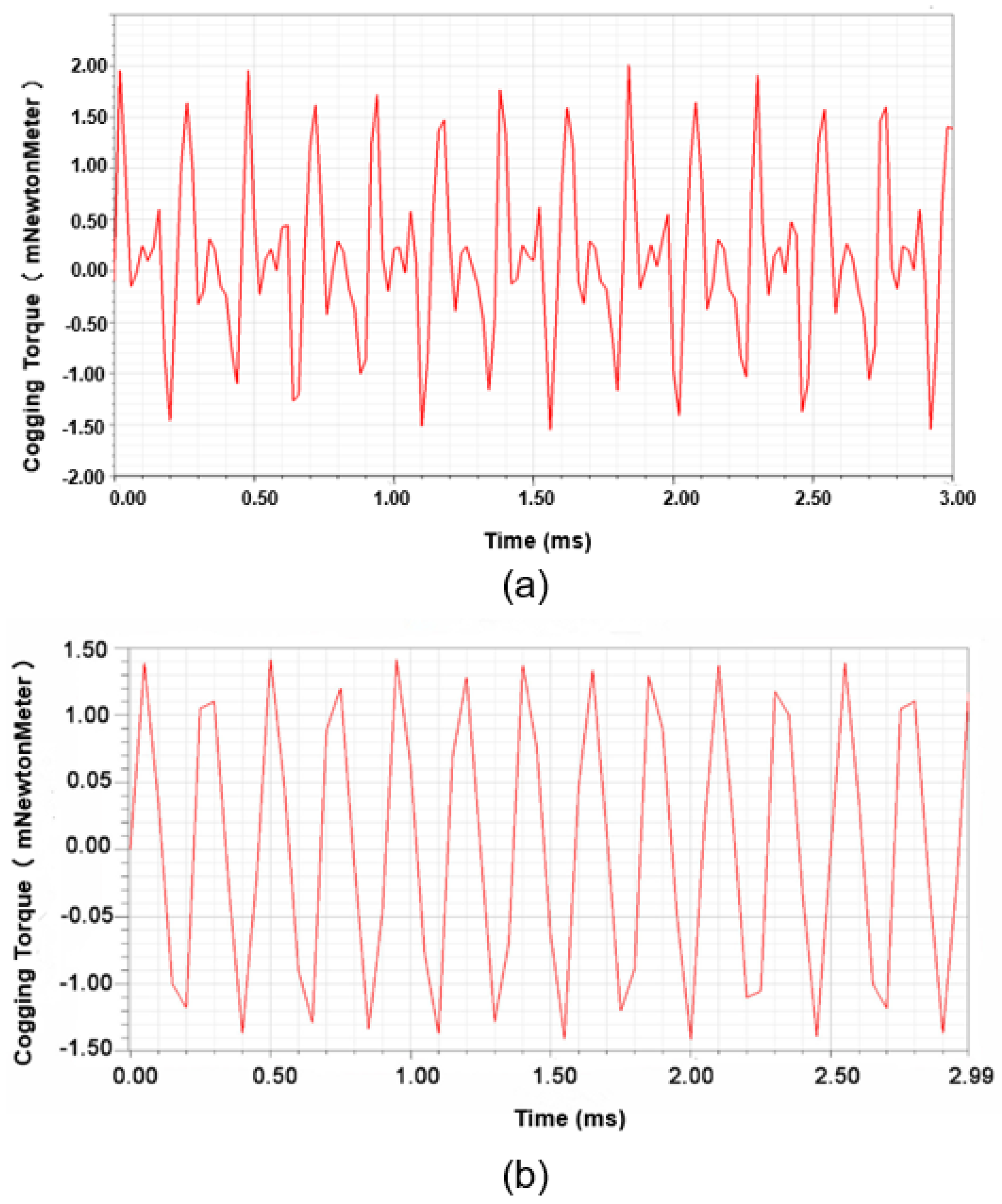
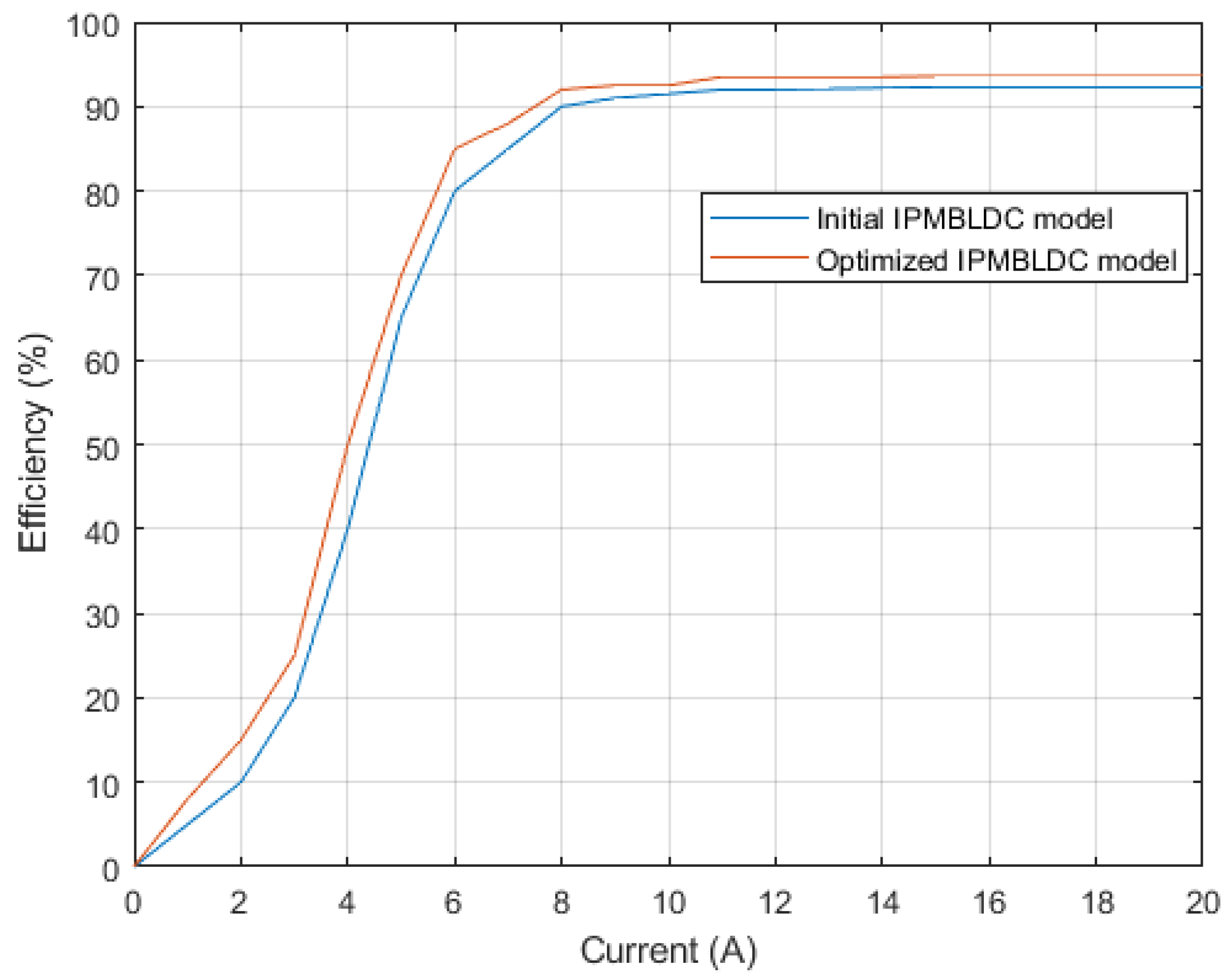
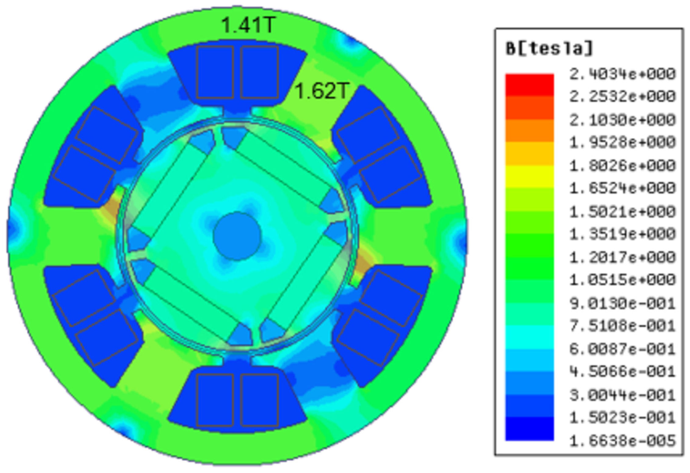
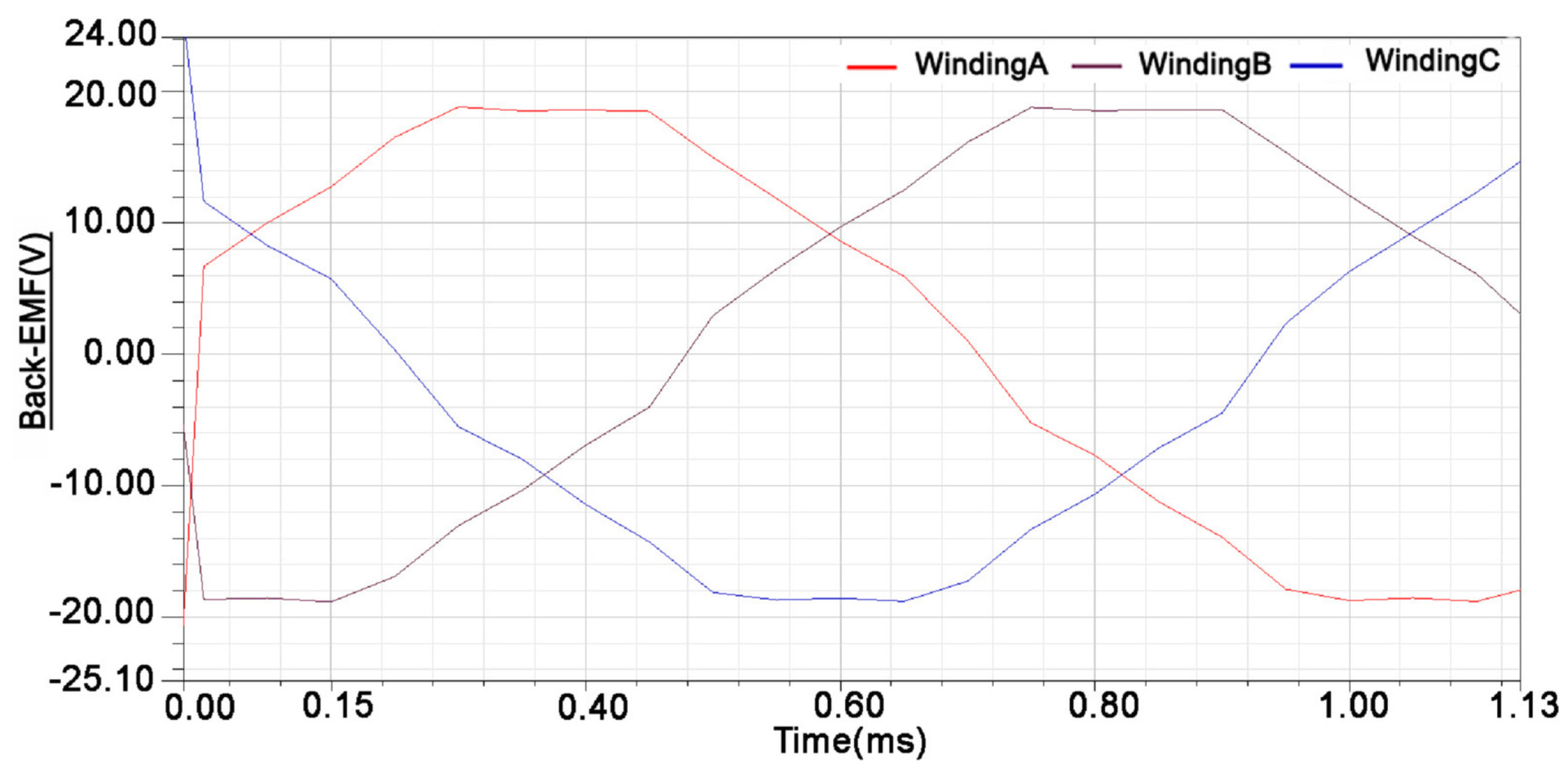
4.1. Optimization and Simulation

To verify the magnetic circuit model and the design parameters, the 2D Finite element analysis has been used. Table 3 shows the primary design results, calculated results and the FEA results for changing the magnetic bridge width. We assume the flux density of the bridge is limited to 1.8 Tesla and the flux density of the rib is limited to 2 Tesla. From the Table 3, we can see that the 2-D finite element analysis verifies our calculation and design parameters.
For this IPMBLDC motor, ANSYS Maxwell 2D (Release 18. 0, Ansys, Inc, Canonsburg, PA, USA) is used to evaluate and optimize the motor based on the initial parameters obtained from the design equation. The goal of the optimization is to reduce the cogging torque and increase the efficiency. Some parameters such as air-gap length magnet length, tooth bridge, rotor bridge depth and so on will be slightly modified to get better performance. The dimensions of the initial and optimized IPMBLDC motor model are shown in Table 4.
Cogging torque is the consequence of the interaction between the rotor-mounted permanent magnet field and the stator teeth. It will produce a pulsating torque that does not contribute to the net effective torque. The waveform of the cogging torque for the initial IPMBLDC motor model and optimized IPMBLDC motor model at rated speed is shown in Figure 16. It is shown that the peak value of the initial IPMBLDC motor cogging torque is around 0.02 Nm and the peak value of the optimized IPMBLDC motor cogging torque is around 0.014 Nm. The peak value of the cogging torque reduces 30 % after optimization. In order to get high torque, concentrated windings are used, so the value of cogging torque is reasonable for 6-slots, 4-pole motor. For the impact wrench application, there are no critical requirements for cogging torque.
The efficiency versus current plot of the initial and optimized IPMBLDC motor model is shown in Figure 17. The plot shows that the optimized model has around 1.5 % higher efficiency than the initial IPMBLDC motor. Theoretically, the optimized IPMBLDC motor has around 93 % efficiency at the rated current.
The motor must meet the following flux density constraints: (1) Stator tooth flux density lower than 2T; (2) Stator yoke flux density lower that 1.5T; (3) Rotor yoke flux density lower than 1.5T. Through the finite element simulation analysis, the flux distribution of the final designed structure is shown in Figure 18.
From the Maxwell 2D simulation results, it can be seen that the tooth average flux density is 1.62T, the yoke average flux density is 1.41T, and the average air-gap flux density is 0.585T. The web flux density is around 1.76T, and rib flux density is around 1.95T. The web flux density is close to the assumed value. All the results satisfy the requirements.
The no-load back-EMF simulation analysis of the IPMBLDC motor is given in Figure 19. The line to line EMF has a 60 flat-top with delta connection.

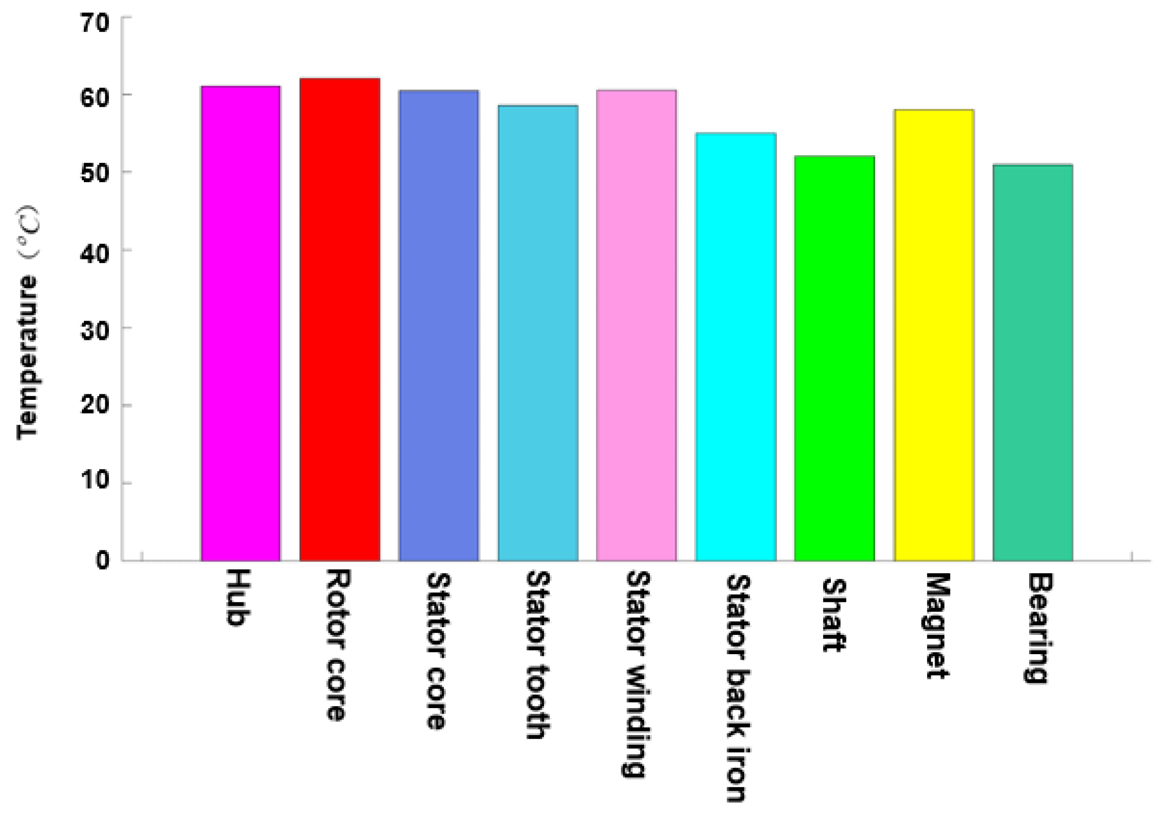
4.2. Thermal Analysis and Cooling
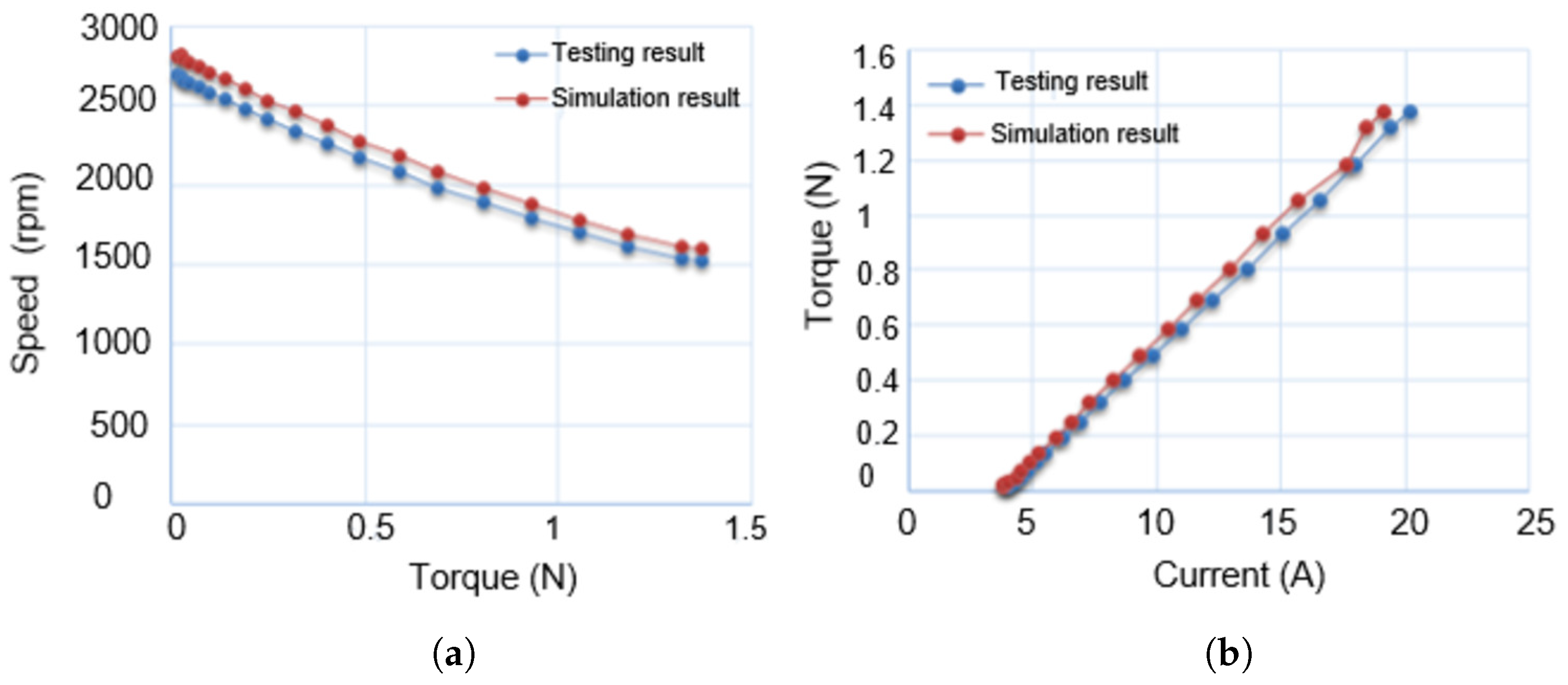
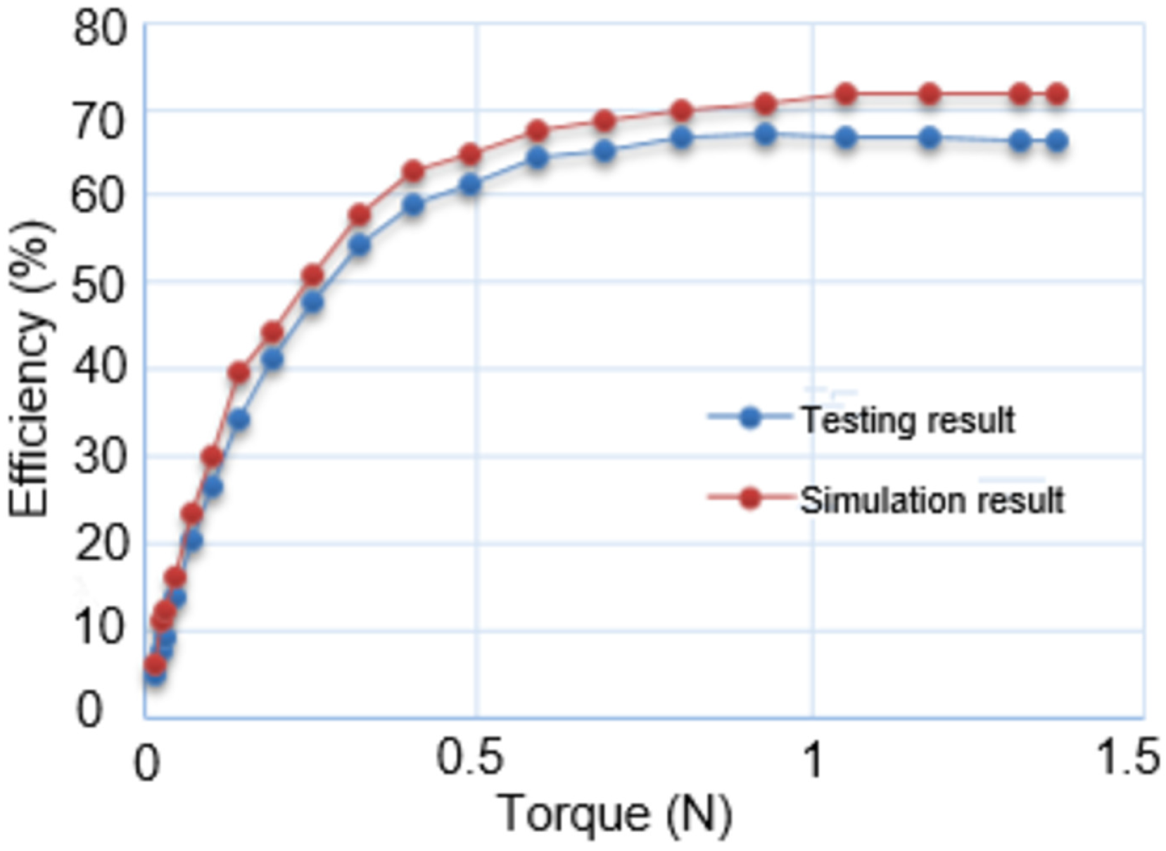
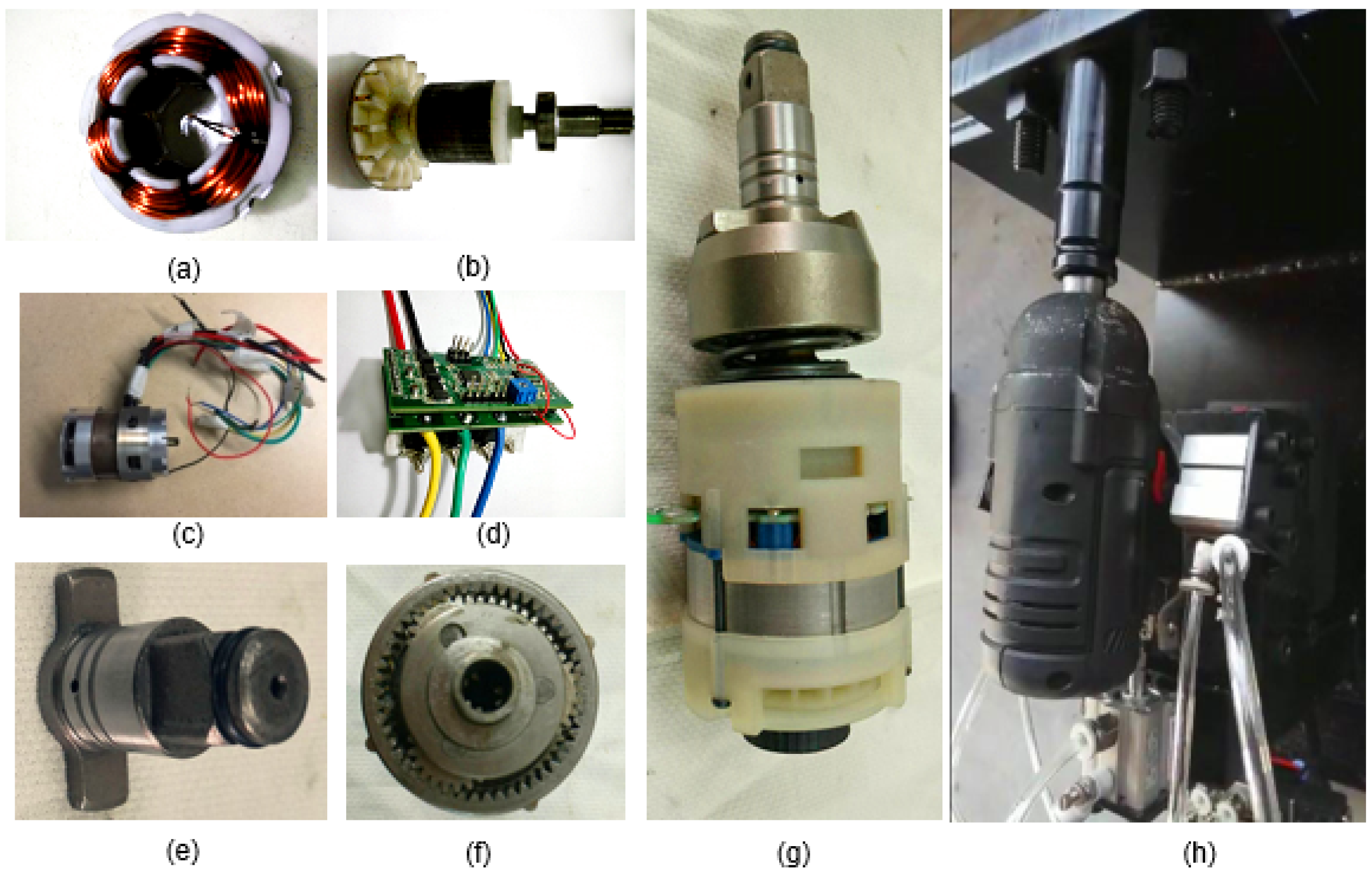
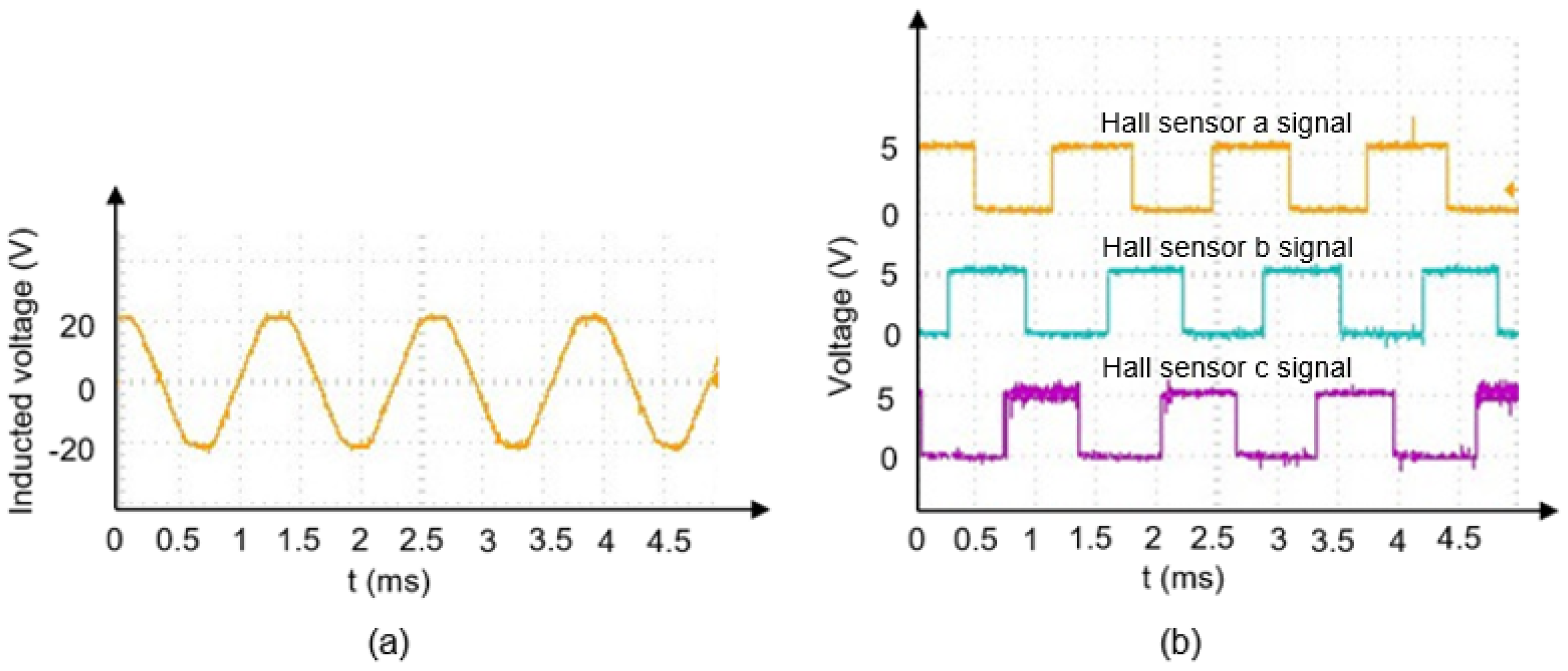
In order to avoid demagnetization, the magnet’s temperature needs to be kept under control. To preserve the life of the insulation and bearing, excessive heating of the surrounding and injury caused by touching hot surface, the temperature rise of the winding and frame should be kept below a level. In this paper, a fan is used for cooling and power MOSFETs are soldered on an aluminum board. We can see from the Figure 20 that the peak temperature appearing in the rotor is around 62 C after one hour. Actually, the motor of electric impact wrench is not expected to be in continuous operation, and therefore that peak temperature will never be reached.

5. Experiment

The prototype is shown in Figure 21. Figure 21a–d show the stator, rotor assembled with a shaft, bearing and fan, the whole IPMBLDC motor, and the control board respectively. Shock block and plane gear system are shown in Figure 21e,f. Figure 21g shows the IPMBLDC motor connected with the mechanical system. Testing setup is shown in Figure 21h. The induced back EMF of the IPMBLDC motor and hall sensor position of the IPMBLDC motor control board are shown in Figure 22. The ampere-conductor distribution of the stator remains constant and fixed in space for a predetermined commutation interval while the magnet rotates past it, producing a linear variation in phase flux-linkage and from it a flat-topped EMF waveform.
We can see the flux density of the air gap and Fast Fourier transform analysis of flux density of air gap at no load in Figure 23a,b respectively. Even harmonics are canceled, only odd harmonics exist, which indicates that the harmonics of air gap flux density distribution is good.
Figure 24a shows the testing and simulated results of IPMBLDC motor speed vs. torque and current vs. torque. We use the fixed torque wrench to load the bolt, then use the impact wrench to unload the bolt. As the torque increases, the motor speed decreases. The simulated speed of IPMBLDC motor at no load is around 2780 rpm, and the tested speed is a litter lower; the simulated speed decreases to around 1602 rpm, and the tested speed decreased to around 1375 rpm at maximum torque. The simulated current increased to 19 A, and the tested current increased to 21 A at the maximum torque as it can be seen from Figure 24b.
Figure 25 shows that the whole system of electrical wrench simulation efficiency is around 72% and testing efficiency is around 67 % at full load. The efficiency calculation is based on η s y s t e m = T w n w 9550 V B I B , where T w is wrench torque, n w is wrench rotating speed, V B is battery voltage and I B is battery current. For the simulation, some mechanical transmit losses are neglected, this is why the testing efficiency is 5% lower than simulation efficiency. The testing power loss includes the motor power losses, shock block system losses and some other mechanical losses.

6. Conclusions

In this paper, we introduced an analytical method to design the IPMBLDC motor and a new mechanical transmission structure for electrical impact wrench step by step. The improved magnetic circuit model has been established to calculate the coefficient of the flux leakage and working point of a permanent magnet. The design has been optimized and verified using MAXWELL 2D analysis based on the finite element method and MotorSlove packages. The motor has also been fabricated and can satisfy all the design requirements for electric impact wrench application. The new impact mechanical structure and working principle, the planetary gear reduce transmission ratio formula, as well as a dynamic model of main pressure spring and shock block in the impact process are also elaborated. The whole system of the impact wrench was fabricated as well. The future research of this IPMBLDC motor application will focus on the advanced IPMBLDC motor control design applied to the fixed torque impact wrench. We will add the current loop, use the encoder, resolver or sensorless control to replace the hall sensor board.

Author Contributions

Each of the authors contributed to the preparation of this research paper. Chengyuan He proposed the analytical electrical and mechanical design idea and model, calculated the key parameters, finished main simulations, and wrote the paper. He also contributed to the fabrication and experimental testing work. Thomas Wu contributed to review and edit the manuscript.

Funding

This research received no external funding.

Conflicts of Interest

There is no conflict of interest.

References

  1. Jang, S.M.; Cho, H.W.; Choi, S.K. Design and Analysis of a High-Speed Brushless DC Motor for Centrifugal Compressor. IEEE Trans. Magn. 2007, 43, 2573–2575. [Google Scholar] [CrossRef]
  2. He, C.; Wu, T.; Wu, W.; Chow, L.; Harms, J.; Taylor, D.R. Design, analysis and experiment of a high efficiency permanent magnet truck alternator. In Proceedings of the 43rd Annual Conference of the IEEE Industrial Electronics Society (IECON 2017), Beijing, China, 29 October–1 November 2017. [Google Scholar]
  3. Seol, H.S.; Kang, D.W.; Jun, H.W.; Lim, J.; Lee, J. Design of Winding Changeable BLDC Motor Considering Demagnetization in Winding Change Section. IEEE Trans. Magn. 2017, 53, 1–5. [Google Scholar] [CrossRef]
  4. Feng, J.; Liu, K.; Wang, Q. Scheme based on buck-converter with three phase H-bridge combinations for high-speed BLDC motors in aerospace applications. IET Electr. Power Appl. 2018, 12, 405–414. [Google Scholar] [CrossRef]
  5. Li, H.; Li, W.; Ren, H. Fault-tolerant inverter for high-speed low-inductance BLDC drives in aerospace applications. IEEE Trans. Power Electron. 2017, 32, 2452–2463. [Google Scholar] [CrossRef]
  6. Batzel, T.D.; Lee, K.Y. Electric Propulsion with Sensorless Permanent Magnet Synchronous Motor: Implementation and Performance. IEEE Trans. Energy. Convers. 2005, 20, 575–584. [Google Scholar] [CrossRef]
  7. Ko, J.-S.; Choi, J.-S.; Chung, D.-H. Maximum Torque Control of an IPMSM Drive Using an Adaptive Learning Fuzzy-neural Network. J. Power Electron. 2012, 12, 468–477. [Google Scholar] [CrossRef]
  8. Kim, K.-T.; Kim, K.-S.; Hwang, S.-M.; Kim, T.-J.; Jung, Y.-H. Comparison of Magnetic Forces for IPM and SPM Motor with Rotor Eccentricity. IEEE Trans. Magn. 2001, 37, 3448–3451. [Google Scholar]
  9. He, C.; Wu, T. Desing and analysis of a V-type fractional-slots IPMSM with distributed winding for electric vehicles. In Proceedings of the XII Internatinal Conference on Electrical Machines(ICEM), Lausanne, Switzerland, 4–7 September 2016; pp. 1459–1465. [Google Scholar]
  10. Kim, H.S.; Kwon, B.I. Optimal design of motor shape and magnetisation direction to obtain vibration reduction and average torque improvement in IPM BLDC motor. IET Electr. Power Appl. 2017, 11, 378–385. [Google Scholar] [CrossRef]
  11. Lee, Y.S.; Kim, K.T.; Hur, J. Finite-Element Analysis of the Demagnetization of IPM-Type BLDC Motor with Stator Turn Fault. IEEE Trans. Magn. 2014, 50, 889–892. [Google Scholar] [CrossRef]
  12. Wang, X.; Li, Q.; Wang, S.; Li, Q. Analytical Calculation of Air-Gap Magnetic Field Distribution and Instantaneous Characteristics of Brushless DC Motors. IEEE Trans. Energy Convers. 2003, 18, 424–432. [Google Scholar] [CrossRef]
  13. Maetani, T.; Morimoto, S.; Yamamoto, K.; Isomura, Y.; Watanabe, A. Comparing brushless dc motors: A method ofsuppressing the shaft voltage even in a grounded motor frame. IEEE Ind. Appl. Mag. 2015, 21, 29–35. [Google Scholar] [CrossRef]
  14. Park, J.K.; Wellawatta, T.R.; Ullah, Z.; Hur, J. New equivalent circui of IPM-type BLDC motor for calculation of shaft voltage by considering electric and magnetic fields. IEEE Trans. Ind. Appl. 2016, 52, 3763–3771. [Google Scholar] [CrossRef]
  15. Shin, K.H.; Choi, J.Y.; Cho, H.W. Characteristic analysis of interior permanent-magnet synchronous machine with fractional-slot concentrated winding considering nonlinear magnetic saturation. IEEE Trans. Appl. Supercond. 2016, 26. [Google Scholar] [CrossRef]
  16. Sashidhar, S.; Fernandes, B.G. Braking Torque Due to Cross Magnetization in Unsaturated IPM BLDC Machines and Its Mitigation. IEEE Trans. Magn. 2017, 53. [Google Scholar] [CrossRef]
  17. Fan, Y.; Li, C.; Zhu, W.; Zhang, X.; Zhang, L.; Cheng, M. Stator Winding Inter-turn Short Circuit Faults Severity Detection Controlled by OWSVPWM without CMV of Five-phase FTFSCW-IPM. IEEE Trans. Ind. Appl. 2017, 53, 194–202. [Google Scholar] [CrossRef]
  18. Duan, H.; Gan, L. Orthogonal multiobjective chemical reaction optimization approach for the brushless DC motor design. IEEE Trans. Magn. 2015, 51. [Google Scholar] [CrossRef]
  19. Nasiri-Zarandi, R.; Mirsalim, M.; Cavagnino, A. Analysis, optimization, and prototyping of a brushless DC limited-angle torque-motor with segmented rotor pole tip structure. IEEE Trans. Ind. Electron. 2015, 62, 4985–4993. [Google Scholar] [CrossRef]
  20. Lim, D.K.; Yi, K.P.; Jung, S.Y.; Jung, H.K.; Ro, J.S. Optimal design of an interior permanent magnet synchronous motor by using a new surrogate-assisted multi-objective optimization. IEEE Trans. Magn. 2015, 51. [Google Scholar] [CrossRef]
  21. Wu, S.; Zhao, X.; Jiao, Z.; Luk, P.C.K.; Jiu, C. Multi-objective optimal design of a toroidally wound radial-flux halbach permanent magnet array limited angle torque motor. IEEE Trans. Ind. Electron. 2017, 64, 2962–2971. [Google Scholar] [CrossRef]
  22. Insinga, A.R.; Bjørk, R.; Smith, A.; Bahl, C.R.H. Globally optimal segmentation of permanent-magnet systems. Phys. Rev. Appl. 2016, 5, 064014. [Google Scholar] [CrossRef]
  23. Wu, S.; Zhao, X.; Li, C.; Jiao, Z.; Qu, F. Multiobjective Optimization of a Hollow Plunger Type Solenoid for High Speed On/Off Valve. IEEE Trans. Ind. Electron. 2018, 65, 3115–3124. [Google Scholar] [CrossRef]
  24. Kim, D.W.; Park, G.J.; Lee, J.H.; Kim, J.W.; Kim, Y.J.; Jung, S.Y. Hybridization Algorithm of Fireworks Optimization and Generating Set Search for Optimal Design of IPMSM. IEEE Trans. Magn. 2017, 53. [Google Scholar] [CrossRef]
  25. Han, W.; Tran, T.T.; Kim, J.W.; Kim, Y.J.; Jung, S.Y. Mass ionized particle optimization algorithm applied to optimal FEA-based design of electric machine. IEEE Trans. Magn. 2016, 52. [Google Scholar] [CrossRef]
  26. Ma, C.; Li, Q.; Lu, H.; Liu, Y.; Gao, H. Analytical model for armature reaction of outer rotor brushless permanent magnet DC motor. IET Electr. Power Appl. 2018, 12, 651–657. [Google Scholar] [CrossRef]
  27. Kim, H.S.; You, Y.M.; Kwon, B.I. Rotor shape optimization of interior permanent magnet BLDC motor according to magnetization direction. IEEE Trans. Magn. 2013, 49, 2193–2196. [Google Scholar] [CrossRef]
  28. Sudhoff, S.D.; Krause, P.C. Operation Modes of the Brushless DC Motor with a 120° Inverter. IEEE Trans. Energy Convers. 1990, 5, 558–564. [Google Scholar] [CrossRef]
  29. SimPowerSystems: Model and Simulate electrical Power systems. In User’s Guide; The MathWorks Inc.: Natick, MA, USA, 2010.
  30. Hendershot, J.R.; Miller, T.J.E. Design of Brushless Permanent-Magnet Machines; Motor Design Books: Venice, FL, USA, 2010; pp. 5–23. [Google Scholar]
  31. Nagrial, M.H.; Rizk, J.; Hellany, A. Design and Performance of Interior Permanent Magnet Motors with Saturating Magnetic Bridge. In Proceedings of the International Conference on Electric Machines and Drives Conference (IEMDC 2009), Miami, FL, USA, 3–6 May 2009; pp. 922–927. [Google Scholar]
  32. Tang, R.Y. Modern Permanent Magnet Machines Theory and Design; China Machine Press: Beijing, China, 1997; pp. 161–270. (In Chinese) [Google Scholar]
Figure 1. Brushless DC motor design flow.
Energies 11 01360 g001
Figure 2. Hall sensor board designed by Altium Designer.
Energies 11 01360 g002
Figure 3. Flux density curve and flux of one pole pair.
Energies 11 01360 g003
Figure 4. Stator slot dimensions.
Energies 11 01360 g004
Figure 5. Magnet and flux guide dimensions.
Energies 11 01360 g005
Figure 6. B-H curve of a permanent magnet material.
Energies 11 01360 g006
Figure 7. IPMBLDC motor air-gap magnetic field.
Energies 11 01360 g007
Figure 8. Simplified IPMBLDC motor air-gap magnetic field.
Energies 11 01360 g008
Figure 9. Half of IPMBLDC motor configurations.
Energies 11 01360 g009
Figure 10. IPMBLDC motor with (a) equivalent magnetic circuit and (b) simplification of the equivalent magnetic circuits.
Energies 11 01360 g010
Figure 11. Flow chart of the procedure of the calculation.
Energies 11 01360 g011
Figure 12. Mechanical structure of impact wrench.
Energies 11 01360 g012
Figure 13. Simple planetary gear mechanism.
Energies 11 01360 g013
Figure 14. The basic spring design procedure.
Energies 11 01360 g014
Figure 15. (a) Shock block shape (b) Simplified shock block shape.
Energies 11 01360 g015
Figure 16. Plots of cogging torque (a) initial IPMBLDC motor model (b) optimized IPMBLDC motor model.
Energies 11 01360 g016
Figure 17. Efficiency vs. current of initial and optimized IPMBLDC motor model.
Energies 11 01360 g017
Figure 18. Magnetic flux distribution within the proposed magnetic structure: hot magnetic spot.
Energies 11 01360 g018
Figure 19. The no load back-EMF of the IPMBLDC motor.
Energies 11 01360 g019
Figure 20. Peak temperature of IPMBLDC motor parts.
Energies 11 01360 g020
Figure 21. Prototype of IPMBLDC motor for electric impact wrench: (a) stator; (b) rotor assembled with a shaft, bearing and fan; (c) the whole IPMBLDC motor; (d) the control board; (e) shock block; (f) plane gear system; (g) the IPMBLDC motor connected with the mechanical system; (h) testing setup.
Energies 11 01360 g021
Figure 22. Oscilloscope trace of (a) phase a inducted EMF waveform and (b) signals from hall sensor board.
Energies 11 01360 g022
Figure 23. (a) The flux density of air gap and different order harmonic waveforms showing with different color; (b) The fast Fourier transformation (FFT) analysis of air gap.
Energies 11 01360 g023
Figure 24. (a) Speed vs. torque; (b) Torque vs. current.
Energies 11 01360 g024
Figure 25. Efficiency vs. torque.
Energies 11 01360 g025
Table 1. Magnetic circuit calculation.
No-load main flux Φ 0 = α m B r A m k l s
Average air-gap flux density B g = Φ 0 α p τ 1 L e
Air-gap MMF F g = 2 B a ( d σ + k c ) μ 0
Total MMF Σ F = F g + F s t + F s y + F r y
Main magnetic permeability λ δ = Φ δ Σ F
Per-unit value of the main magnetic permeability ξ δ = 2 ξ δ h m μ 0 μ r A m
Magnet to magnet flux leakage Φ m m = B w 1 w 1 L e / 2
Magnet end flux leakage Φ m l = B w 2 w 2 L e
Total flux leakage Φ σ = Φ m m + Φ m l
Flux leakage coefficient k l s = Φ δ Φ δ + Φ σ
Magnet operating point α m = k l s ξ δ k l s ξ δ + 1
Table 2. Parameters of pressure spring.
Material60Si2MnA
Installed length60 mm
Minimum amount of elastic deformation S 1 5 mm
Maximum amount of elastic deformation S 2 14 mm
Impact stroke length h9 mm
Angle of spiral β 22 C
Out diameter of a coil D c 71 mm
Inner diameter of a coil d c 60 mm
Total number of winding N 1 6
Number of active winding N 2 3
Table 3. Calculated results and FEA results.
Initial Design ParametersCalculated ResultsFEA
k ls α m w 1 w 2 B δ k ls α m B δ k ls
1.15 0.85 1 0.5 0.598 1.1522 0.861 0.585 1.149
1.15 0.85 1.1 0.5 0.595 1.1539 0.863 0.581 1.1523
1.15 0.85 1.2 0.5 0.591 1.1542 0.865 0.576 1.1531
Table 4. The dimensions of the initial and optimized IPMBLDC motor model.
IPMBLDC motor ModelInitial ModelOptimized Model
Number of the slots/poles 6 / 4 6 / 4
Stator outer diameter/mm4848
Stator inner diameter/mm2424
Air-gap length/mm 0.4 0.5
Magnet width/mm2.2 2.5
Magnet length/mm 9.5 9.5
Rotor bridge depth/mm 0.7 0.5
Tooth width/mm 5.35 5.5
b s 0 /mm 1.8 1
Rotor magnet web/mm 1.2 1

