Abstract
The stator side of a double-fed induction generator (DFIG) is directly connected to the grid, so the DFIG is sensitive to a voltage drop caused by power system faults. A double resistors braking method based on fuzzy control is proposed to improve the performance of low-voltage ride through (LVRT) in this paper. Based on the mathematical model of DFIG, it analyzes the function of a series dynamical braking resistor (SDBR) theoretically. The series impedance value of the SDBR is determined by the variation of the rotor’s open circuit voltage, the voltage and current of the stator and the rotor, and also the heat capacity of the SDBR. In order to improve the LVRT capability of a DFIG under different fault grads, a double series resistors braking mode is presented. Through adopting a fuzzy control strategy, double series resistor switching is implemented. With the example system, the correctness and validity of the proposed method is verified.
1. Introduction
With the rapid development of the wind power industry, large-scale wind farms will have effects on the stability of the power grid. Many countries or units have set guidelines for grid connection and have given specific requirements for low-voltage ride through capability. As the main type of wind power generation, double-fed induction generators (DFIGs) have obvious advantages in flexible grid connection and power tracking; however, for the following reasons, DFIGs are more sensitive to power grid faults: (1) the stator of a DFIG is directly connected with the grid, which is easily affected by the power grid; and (2) the back-to-back converter is connected to the rotor side, and the overvoltage of the power electronic devices in the converter is limited [1,2].
At present, improvement of the low-voltage crossing performance of DFIGs is generally studied in the following aspects: (1) optimization of the control strategy of the DFIG (although these methods have limited low-voltage ride through (LVRT) ability and can only be used for a slight short circuit fault) [3,4,5]; and (2) power electronic equipment [6,7,8] to assist in LVRT including a rotor parallel crowbar circuit, a static synchronous compensator (STATCOM), unloading resistance for the rotor direct current (DC) capacitor, a series dynamical braking resistor (SDBR), etc. The costs of power and electronic equipment are high, which are generally used for serious failure.
Various solutions have been proposed from the two aspects above. On one hand, the optimization of the control strategy solutions is proposed; for example, the virtual damping flux-based strategy can suppress the rotor current during the transient states of grid voltage drop and recovery, the negative sequence current compensation strategy can smooth the electromagnetic torque and reactive power during steady-state faults [9,10]. And the optimization of the control strategy is complex in the period of unsymmetrical faults [11,12,13]. On the other hand, hardware solutions have also been proposed. A DFIG with a crowbar circuit is a very common solution for LVRT [14,15], but this solution is confined to the rotor side, such as limiting DC capacitor voltage and rotor current. A STATCOM can improve the LVRT performance of a wind farm [16], and it is often used in collaboration with crowbar circuits. The SDBR in [17] could improve the LVRT capacity of a DFIG, and the bypass switching control mode uses the method introduced in [18]. They realized the switching function of the SDBR when the fault occurred or removed, but it could not change the switching state according to the degree of failure. The switching strategy of different SDBRs and the effect under different power factors are current research topics [19]. The effective position of the SDBR in the DFIG structure was investigated using different types of switching signals in [20,21], but they have no specific research on the SBDR controller.
In this paper, a double resistors braking method based on fuzzy control is proposed, which is based on the system characteristics of a DFIG at different voltage drop depths. The double resistance switching mode of an SDBR is also designed. The series resistance values are selected by the open circuit voltage and the resistor’s heat capacity. In order to improve the LVRT performance of the DFIG, the fuzzy control mode is used to realize double resistance switching.
Compared with existing LVRT devices, the contributions of the proposed method can be described as:
- (1)
- There are few studies on the value of series resistance. In addition to the stator and rotor voltage and current, the open circuit voltage and the heat capacity of the brake resistance are considered in this paper, and the range of the braking resistance is designed.
- (2)
- The proposed double resistance braking mode can reduce active power loss, reduce the work time of each resistor, and improve the service life of resistors under the same LVRT performance.
- (3)
- The use of a fuzzy control strategy can precisely control two braking resistors, and avoid the instability caused by continuous switching to the system in comparison with the existing methods.
2. Theoretical Analysis of a Series Dynamical Braking Resistor (SDBR) in a Double-Fed Induction Generators (DFIG)
2.1. Basic Structure of an Series Dynamical Braking Resistor (SDBR)
The basic topology of the DFIG with an SDBR on the stator side is shown in Figure 1, and the SDBR is composed of a resistor, a bypass switch, and a controller.

Figure 1.
Schematic of a double-fed induction generator (DFIG) with a series dynamical braking resistor (SDBR).
When the system is running normally, the bypass switch is connected and the resistor is short-circuited. The equivalent impedance of the SDBR is close to zero under this circumstance, which has no impact on the system. In order to improve the low-voltage ride through (LVRT) performance of the system, the bypass switch is opened and the resistor is input when voltage sags occur.
2.2. Mathematical Model of a Double-Fed Induction Generators (DFIG)
In an stationary coordinate system, the mathematical model of a DFIG can be expressed as [22]:
where , , , , and represent the voltage, resistance, current, flux, and inductance, respectively; and represent the stator and rotor, respectively; and represent the leakage reactance and mutual impedance, respectively.
is the amplitude of the stator voltage at the moment of voltage drop. The stator voltage in the fault period can be expressed as:
At this time, the stator flux can be expressed as:
where is the initial stator flux at the moment of voltage drop and is the time constant of the stator flux.
2.3. Impact of an SDBR on a DFIG’s Low-Voltage Ride Through (LVRT) Capability
The SDBR on the stator side can improve the terminal voltage and restore the stability of the DFIG. The effects of the SDBR are mainly discussed from the two following aspects:
(1) Voltage of the stator side:
The resistance value of the brake resistor installed on the stator side is set as , is the stator voltage vector of the wind turbine generator, and is the grid voltage. Thus, we have:
Substituting (10) into (1), we have:
Comparing (10) with (11), the stator voltage can be effectively improved by the SDBR on the stator side. Thus, it can improve the LVRT capability of the DFIG under voltage sag.
(2) Stator flux:
Equation (9) can be expressed as after the SDBR is installed, so (8) can be expressed as:
Since , the time constant of stator flux is increased by , which increases the reduction speed of the transient direct current(DC) component of the stator flux. Thus, the DFIG can enter the controllable area as soon as possible. The transient process of the wind turbine after failure of the power grid has been shortened, which helps the DFIG system to meet the requirements of the first stage of the LVRT guide for the transient time of the DFIG.
3. Resistance Value Design Method
According to the theoretical analysis, the bigger the resistance values of the SDBR, the greater the voltage drop on the resistance, and the more obvious the effect on the stator voltage. However, if the resistance value is too large, it will increase the power loss and cause instability of the system. Therefore, a suitable series resistance value is needed. The SDBR on the stator side also has a greater impact on the rotor side, so it is too optimistic to select a resistance value only according to the stator voltage and flux. The relationship between the open circuit voltage of the rotor and the series resistance and the voltage sag is analyzed in this paper.
The voltage drop depth is p [23], and the open circuit voltage of the rotor can expressed as:
When the series brake resistor is connected, (9) and (13) are combined to give:
The relationship between the amplitude of the open circuit voltage of the rotor, the drop depth of the voltage, and the resistance value of the SDBR can be obtained by (15):
In order to express the relationship between the open circuit voltage of the rotor, the resistance value of the series brake, and the depth of the voltage drop more intuitively, the following set of data of the 1.5 MW DFIG is taken: , , , , . It can be calculated that and from (5) and (6); in consideration of the ride-through characteristics for 625 ms in the LVRT guide, a three-dimensional diagram is shown in Figure 2. The z-axis in the diagram is the multiple of the stator voltage .

Figure 2.
Rotor open circuit voltage.
The relationship between the open circuit voltage of the rotor, the drop depth of the voltage, and the series resistance can be seen in Figure 2. Due to the limited overvoltage in the rotor converter, the DFIG has strict requirements for the open circuit voltage of the rotor during the voltage sag.
Therefore, the open circuit voltage of the rotor is limited to the following condition after the voltage sag:
According to (16) and Figure 2, it is easy to get the range of resistance values according to the voltage drop degree of the system. For example, if the drop depth of the voltage is 0.9, the upper limit of the resistance value is approximately 0.6 pu.
In addition to the open circuit voltage of the rotor, the series resistance on the stator will also cause changes to other physical quantities. In the 1.5 MW DFIG unit, an SDBR with different values is simulated. The stator voltage and current, the amplitude of the rotor current, and the DC capacitor voltage for the unitary value are shown in Figure 3, where the stator voltage is the valid value, the DC voltage is the amplitude value, and the rotor and stator current are the maximum value.

Figure 3.
Current and voltage circumstances of the double-fed induction generators (DFIG).
It can be seen in Figure 3 that the stator current, the rotor current, and the DC voltage will be reduced with the increase of the series resistance value in a certain range, and the voltage of the stator will also be increased. However, when the resistance value is greater than 0.7 pu, the system will be unstable, and both the stator and rotor current begin to increase. Although the system is still in a stable state, the amplitude of DC capacitance voltage is relatively large when the resistance value of the SDBR is between 0.6–0.7 pu, which will affect the stability of the DFIG. Therefore, the upper limit of the series brake resistance is approximately 0.5 pu, considering the low-voltage crossing guide and the stability of the system.
As the series brake resistance is limited by its own heating capacity, if the brake resistance value is too small, it may cause damage or even destruction of the SDBR because of a large current. This paper calculates the heat dissipation of the series brake resistance. The temperature rise of the SDBR needs to meet the following condition:
where is the temperature increase of the cooling media, is the temperature rise of the brake resistance relative to the cooling medium, is the maximum allowable temperature increase of the SDBR, is the maximum allowable power of brake resistance, and , , , , and are the volume, specific heat capacity, conversion coefficient, heat transfer coefficient, and heat transfer area of the cooling medium, respectively.
It is easy to calculate the lower limit of the series brake resistance from (18):
where is the power correction factor for external brake resistance.
Taking the 1.5 MW DFIG above as an example, the cooling medium is water, is 750 K, the correction coefficient is selected to be 7 when the braking time is short, and is the rated voltage of the stator at the time of failure. It is calculated that the range of the resistance value is . In summary, the value of the resistance in the 0.133–0.5 pu range can not only meet the requirements of the open circuit voltage of the rotor, but can also meet the heat radiation requirements of the brake resistance itself.
4. Double Resistance Switching Based on Fuzzy Control
4.1. Basic Principle of Double Resistance Switching
Due to the possibility of different degrees of voltage sags in the system, if only a resistor is set by the method introduced in the upper section, the larger resistance value will cause great active power loss or even the instability of the system in a slight short circuit fault. So, a type of SDBR with double resistance switching is proposed in this paper.
The voltage of the DFIG falls quickly after a voltage sag, and it also causes the generator to accelerate because of the decrease in electromagnetic torque. Therefore, this paper selects the voltage drop depth p and the angular speed of the DFIG as the criteria for double resistance switching. When the depth of the voltage drop is small and the angular velocity of the DFIG is slightly changed, the resistance of the smaller value is put into the system. The resistance of the larger value is put into the system when the depth of the voltage drop is larger or the angular speed of the DFIG is changed greatly. The principle of double resistor switching is as shown in Figure 4.

Figure 4.
Principle of double resistor switching.
In Figure 4, and are the action voltages of the large resistance and the small resistance, respectively, is the rated speed of the rotor of the DFIG, and and are the angular velocity variations of the rotor of the DFIG, which trigger the larger resistance and the smaller resistance, respectively. The upper and lower limits of the braking resistance are obtained by substituting different action voltages into (16) and (18), respectively. According to the change curves in Figure 3, the resistance value range of the SDBR is obtained.
4.2. SDBR Switching Based on Fuzzy Control
There are different combinations between the voltage of the power grid and the angular velocity of the DFIG rotor in different failure states. At this point, the simple logical processing shown in Figure 4 cannot take all cases into account, thus resulting in inaccuracy. It is necessary to have a more complete corresponding rule to control the switching of the double resistance. In order to consider different fault conditions, based on the double resistor switching principle illustrated in Figure 4, a fuzzy controller switching strategy is designed for double resistor SDBRs. As shown in Figure 5, the basic structure of the fuzzy controller consists of the fuzzification interface, the fuzzy inference mechanism, the defuzzification interface, and the knowledge base.
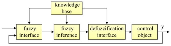
Figure 5.
Fuzzy logical controller structure.
Based on the basic structure of fuzzy control, the fuzzy controller of the double resistance SDBR is designed according to the following steps:
- Step 1:
- The voltage drop depth p and the rotor speed of the DFIG are selected as the control inputs, and the output is the pulse signal that controls the bypass switch.
- Step 2:
- A higher degree of sensitivity of the more pointed membership function of the curve occurs. In this paper, the membership degree function of the triangle is selected.
- Step 3:
- As the input amount p is the voltage drop depth, three language variables were selected according to the voltage without falling, with slight fall, or with serious fall. The rotor speed range corresponding to the variable speed section of the DFIG is limited, so the language variables of the two inputs are positive big (PB), zero (Z), and negative big (NB), respectively, and the universe of discourse is [−2,2]. There are also three language variables for the output, namely PB, Z, and NB, and the universe of discourse is [−2,2] as well. The detailed relationship between the membership function and the universe of discourse is shown in Figure 6.
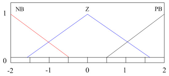 Figure 6. Membership functions of the input and output signals.
The universe of discourse of the input and output is [−2,2], but the signal collected by the controller is not distributed in this range, so the quantization factor and the proportional factor need to be introduced. The potential range of the voltage drop degree p is [0,1], the degree of voltage drop is treated as follows, and the in (19) is the input variable of the voltage drop:
The transfer rate of the DFIG is s, the stator speed is the unit speed, and the normal rotor speed is . According to the speed change range of the DFIG by the existing simulation experiment, the angular velocity of the DFIG is treated as follows, while the input variable of angular velocity is in (20):
The output of the fuzzy controller is the control signal for the bypass switch of the SDBR, and the ratio factor is 1. The output signal is limited, and the limit output range is [−1,1]. The output value of the controller at this time is −1, 1, 0, corresponding to larger resistance, smaller resistance, and no action, respectively.
- Step 4:
- The common methods of fuzzy reasoning are the Mamdani method and the Sugeno method. In this paper, the Mamdani method is selected, and the mean value of the maximum method is chosen as the defuzzification method.
- Step 5:
- In order to put different resistances into the system under different fault conditions, according to the experience of experts, operators, and the results of the existing literature, the fuzzy control rules are designed as Table 1:
 Table 1. Fuzzy control rules.
The three-dimensional control diagram of the fuzzy controller is shown in Figure 7:
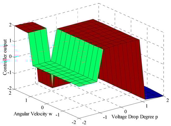
Figure 7.
Three-dimensional diagram of the fuzzy controller.
As seen from Figure 7, the output of the fuzzy controller has two inputs, which are the drop depth of the voltage and the rotor speed of the DFIG. Fuzzy control rules are formulated according to the degrees of voltage drop depth and angular velocity change. The two inputs are passed through the fuzzy controller, and the output is high level, low level, or zero level. The corresponding states of the power grid connected to the DFIG are minor fault, serious fault, or no fault. The output signal of the controller controls the bypass switch of the SDBR and the output value of the fuzzy controller is −1, 1, 0, corresponding to larger resistance, smaller resistance, and no action, respectively.
5. Simulation Result
5.1. Example System
In accordance with the structure shown in Figure 1, a detailed model of the 1.5 MW wind turbine was built by MATLAB/SIMULINK (2013a, MathWorks, Natick, MA, USA), where the wind speed was 12 m/s, the DFIG was connected to the transmission line through the boost transformer, and the step-down transformer was connected to the grid. The control method of the generator side converter was the stator flux-oriented vector control strategy, the field-oriented vector control was used on the grid side, and the generator parameters are shown in Table 2.
Table 2.
Double-fed induction generators (DFIG) parameters.
According to the method introduced in this paper, the resistance values of the series brake resistances were determined as RD1 = 0.35 (pu) and RD2 = 0.15 (pu), the reference capacity was 1.5 MVA, and the reference voltage was 575 V when the unitary value was calculated. The fuzzy controller was used to control the SDBR bypass switch for larger or smaller resistances.
5.2. Dynamic Responses Analysis
In order to analyze the effect of the double resistance SDBR on the LVRT performance of the DFIG, simulation analysis was carried out in the following two cases:
1. Voltage sag severity
The severity fault was set such that the grid side voltage in the system fell by 85% at 3.2 s, and the fault was removed at 3.5 s.
At this time, RD1 was put into the system shortly after the voltage sag, which was controlled by the fuzzy controller. Comparing the systems with or without the SDBR, the DFIG terminal voltage, active power, DC bus voltage, and rotor current were as shown in Figure 8.
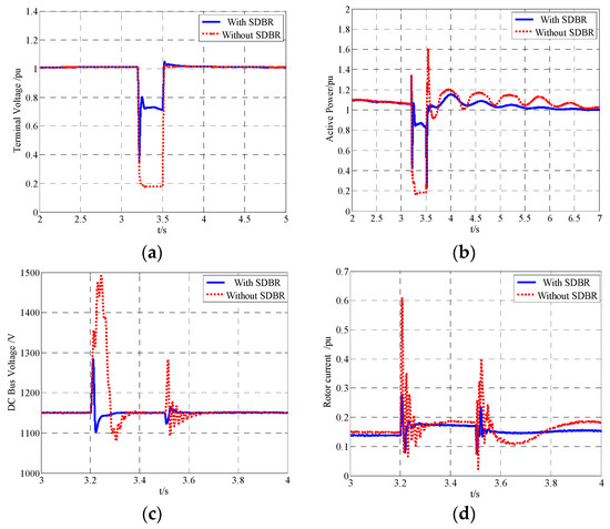
Figure 8.
Effect of the SDBR under severe faults. (a) Stator voltage; (b) Active power; (c) DC bus voltage; (d) Rotor current.
As seen in Figure 8a and b, during a severe grid voltage drop, the input of the SDBR increased the terminal voltage so it could satisfy the requirement of terminal voltage in the LVRT process. After the fault was removed, the recovery procedure of the active power was more rapid and stable, which helped to restrain the acceleration of the DFIG rotor. From Figure 8c and d, it can be seen that when the fault occurred and was removed, the SDBR under fuzzy control effectively limited the DC bus voltage and the rotor current amplitude.
2. Slight voltage sag
The voltage of the grid side fell by 40% at 3.2 s, and the fault was removed at 3.5 s.
At this time, RD2 was put into the system shortly after the failure, under the control of the fuzzy controller. By comparing the SDBR input system and the non-SDBR input system, the terminal voltage, active power, DC bus voltage, and rotor current of the DFIG were as shown in Figure 9.
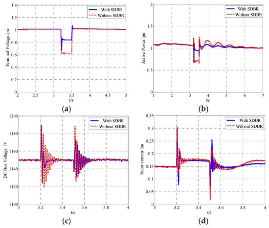
Figure 9.
Effect of the SDBR under lighter failures. (a) Stator voltage; (b) Active power; (c) DC bus voltage; (d) Rotor current.
From Figure 9, it can be seen that the voltage increase was not as large as that of RD1. However, it met the requirements of the slight fault on the voltage rise of the generator terminals, and it could improve the active power, stabilize the reactive power during the fault period, limit the magnitude of the DC bus voltage and the rotor current, and improve the DFIG LVRT capability.
5.3. Control Strategies Comparison
1. Comparison with the traditional series dynamical braking resistor (SDBR)
Traditional SDBR adopts single resistance switching and a single grid voltage criterion, and the resistance value is calculated in a relatively serious failure condition. Therefore, the resistance value is sometimes too large. This paper adopts the method of double braking resistance based on fuzzy control in order to compare this method with the traditional control mode. The following simulation scenes were set:
Scene 1: Set the grid-side voltage in the system to decrease by 50% at 3.2 s; the fault was deteriorated at 3.4 s where the voltage fell to 90%, and the fault was excised at 3.5 s.
Scene 2: Set the grid side voltage in the system to decrease by 90% at 3.2 s; the voltage fell to 50% at 3.4 s, and the fault was excised at 3.5 s.
The traditional action voltage of an SDBR is 0.5, the resistance value is RD1, the controller output is 1 on behalf of the resistance input, and the 0 is not invested. In scene 1 and scene 2, comparing the traditional SDBR and the SDBR in this paper, the output signals of the controller are as shown in Figure 10.
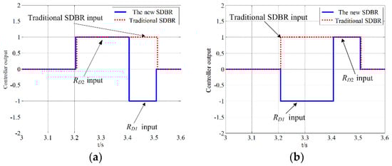
Figure 10.
Output signal of the SDBR controller. (a) Output signal in Scene 1; (b) Output signal in Scene 2.
As shown in Figure 10a, in the 3.2–3.4 s period of scene 1, the fuzzy controller output a high level. The smaller resistance RD2 was put into the system in this period, and the voltage of the grid side at the input time was 0.76 pu. This is a little larger than the traditional SDBR action voltage, so the resistance input time under the fuzzy controller was slightly ahead of the input time of the traditional SDBR, the fuzzy controller output 0, and the large resistance RD1 input at 3.4 s. In this process, the signal changed with the degrees of the voltage sags, and there was no continuous jump of the control signal, which played a good role in the stability of the system. The controller of the traditional SDBR will only put RD1 into the system according to the drop depth at the beginning. It was removed after the fault disappeared, and the input state of the resistance cannot change according to the change in the voltage sag. The output signal of the fuzzy controller in scene 2 is given in Figure 10b, similar to that in (a), and the fuzzy controller could change the resistance of the SDBR to different values based on the voltage sags.
The traditional single resistance and the double resistance SDBRs in this paper are compared in two scenes, and the active power losses are as shown in Figure 11.

Figure 11.
Active power loss of the SDBRs. (a) Active power loss in scene 1; (b) Active power loss in scene 2.
Figure 11 shows that the active power consumed by the double resistance SDBR controlled by the fuzzy controller was obviously less than the traditional single resistance SDBR. The active power loss of the SDBR can be reduced by using different values of resistance according to the degree of voltage sag, which reduces the quantity of heat caused by the consumption of active power and improves the service life of the SDBR. It can selectively invest or remove resistance according to the different degrees of system voltage sags, which reduces the active loss and realizes flexible and accurate SDBR control.
2. Comparison with other low-voltage ride through (LVRT) techniques
In order to validate the performance of the proposed scheme, the crowbar circuit proposed in [24,25] was chosen as a contrast, and DC chopper circuits are usually used with crowbar circuits. A crowbar circuit and a DC chopper circuit were set to protect the DFIG in the fault duration to improve the reliability of the contrast simulation. The coordinated use of the two devices improved the credibility and accuracy of the contrast simulation. The coordinated control strategy of the two devices is introduced in [26]. The simulation conditions were the same as in [25]—that is, a grid voltage dip of 80% with a duration of 200 ms was considered. The comparison between the double resistors braking method proposed in this paper and the existing crowbar and chopper circuits is as follows:
As can be seen from Figure 12, the crowbar circuit also had the function of limiting the rotor current and DC capacitor voltage on the rotor side. However, Figure 12a and b show that the proposed algorithm had considerable advantages in improving the interruption voltage and stabilizing the active output. The terminal voltage level and active output are important factors of LVRT. Moreover, the number of switching times of chopper circuits is large, which is harmful for the life of resistors and insulated-gate bipolar transistors (IGBTs). For the coordinated control of chopper circuits and crowbar circuits, additional coordination and communication links are needed, which will increase the difficulty and costs. Therefore, the proposed scheme had a better performance than the existing technology described above.
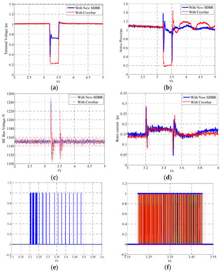
Figure 12.
Simulation results of the SDBR and crowbar circuits. (a) Stator voltage; (b) Active power; (c) DC bus voltage; (d) Rotor current; (e) DC chopper circuit action signal; (f) Inverter control signal of the crowbar circuit.
6. Experimental Results
The steps taken to apply the method described in this paper to an actual system are shown in Figure 13.
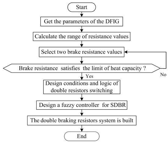
Figure 13.
The realization steps in an actual system.
The realization steps can be described as:
- Step 1.
- Get the parameters of the DFIG.
- Step 2.
- The value range of the series braking resistor is calculated from (13)–(16) in Section 3.
- Step 3.
- Step 4.
- Verify the heat capacity limit of the brake resistors by (17)–(18) in Section 3.
- Step 5.
- Design the conditions and logic of the double resistors switching.
- Step 6.
- Based on the basic structure of fuzzy control, the fuzzy controller of the double resistance SDBR is designed according to the steps proposed in Section 4.2.
- Step 7.
- According to the designed parameters and controllers, the system of the double braking resistors is built.
The real-time simulation platform in the laboratory was built as shown in Figure 14. The major parts of the platform include a host computer, an RT-LAB real-time simulation device (Opal-RT, Montreal, QC, Canada), and a digital storage oscilloscope. RT-LAB is fully integrated with MATLAB/Simulink and supports a large number of input/output (I/O) cards. Firstly, compiling the model established in MATLAB, the corresponding C code can be formed. The second step is to allocate SM_ and SS_ subsystems to the corresponding target cores. The third step is to download the compiled C code to the allocated cores. Finally, the real-time simulation is performed.
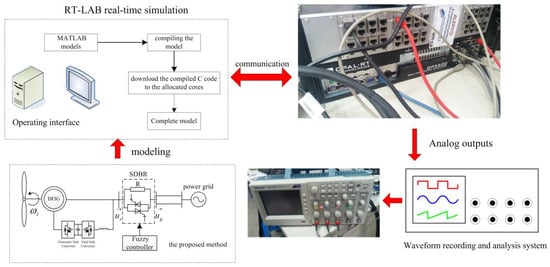
Figure 14.
Laboratory real-time simulation test platform.
The first experimental situation was selected as the serious voltage sag in Section 5.2. The voltage dropped to 15% of its nominal value and the voltage dip lasted for 300 ms. Figure 15a and b shows the experimental results without and with the SDBR.
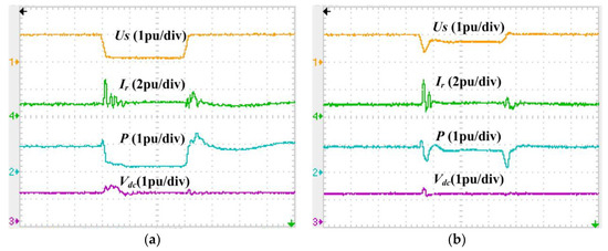
Figure 15.
Experimental results in serious voltage sag. (a) Without the SDBR; (b) With the SDBR.
The eventual experimental results show that the SDBR proposed in this paper could effectively improve the terminal voltage of the DFIG, limit the rotor current and DC capacitor voltage, and improve the output active power of the failure period. The experimental results also show that the SDBR could effectively improve the LVRT capability of the DFIG.
The second experimental situation was selected as Scene 1 in Section 5.3. The results of the experiment are shown in Figure 16.
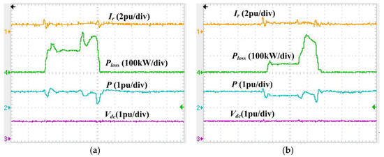
Figure 16.
Experimental results in scene 1. (a) With the traditional SDBR; (b) With the proposed SDBR.
It can be seen from the experimental results, under the premise of the requirements of LVRT, the double resistors braking method could reduce active power loss, and the fuzzy control method could accurately control the switching of the double resistors.
7. Conclusions
Based on fuzzy control, a double resistors braking method for SDBR is proposed in this paper. A theoretical analysis and simulation verification are conducted, and the detailed results are as follows:
- A series SDBR on the stator side has a great influence on the open circuit voltage of the rotor, and there is a certain mathematical relationship between the stator and rotor voltage or current in the case of voltage sag. The suitable range of series resistance can be obtained by these relationships, and also by the heat dissipation capacity of the brake resistance of the SDBR.
- The double resistance braking mode can reduce active power loss, reduce the work time of each resistor, and improve the service life of the resistors with the same LVRT performance.
- An SDBR based on a fuzzy controller can selectively input different resistor sizes according to different system voltage sag levels. It can follow the system in real-time, and can accurately and flexibly control the system.
Author Contributions
All of the authors contributed to this work. H.D. and H.W. performed the modeling and simulation and wrote the manuscript; J.P. and Y.C. researched and summarized the literature; B.X. provided professional advice and reviewed the paper.
Funding
This research received no external funding.
Acknowledgments
This work was supported by the National Key R&D Program of China under Grant 2016YFB0900400.
Conflicts of Interest
The authors declare no conflict of interest.
References
- Wu, Z.; Zhu, C.; Hu, M. Improved Control Strategy for DFIG Wind Turbines for Low Voltage Ride Through. Energies 2013, 6, 1181–1197. [Google Scholar] [CrossRef]
- Geng, H.; Liu, C.; Yang, G. LVRT Capability of DFIG-Based WECS under Asymmetrical Grid Fault Condition. IEEE Trans. Ind. Electron. 2013, 60, 2495–2509. [Google Scholar] [CrossRef]
- Kamel, R.M.; Chaouachi, A.; Nagasaka, K. Enhancement of micro-grid performance during islanding mode using storage batteries and new fuzzy logic pitch angle controller. Energy Convers. Manag. 2011, 52, 2204–2216. [Google Scholar] [CrossRef]
- Hossain, M.J.; Saha, T.K.; Mithulananthan, N.; Pota, H.R. Control Strategies for Augmenting LVRT Capability of DFIGs in Interconnected Power Systems. IEEE Trans. Ind. Electron. 2013, 60, 2510–2522. [Google Scholar] [CrossRef]
- Makrini, A.E.; Karkri, Y.E.; Boukhriss, Y.; Elmarkhi, H.; Moussaoui, H.E. LVRT control strategy of DFIG based wind turbines combining passive and active protection. Int. J. Renew. Energy Res. 2017, 7, 1258–1269. [Google Scholar]
- Guo, W.; Xiao, L.; Dai, S.; Xu, X.; Li, Y.; Wang, Y. Evaluation of the Performance of BTFCLs for Enhancing LVRT Capability of DFIG. IEEE Trans. Power Electron. 2015, 30, 3623–3637. [Google Scholar] [CrossRef]
- Espinoza, N.; Bongiorno, M.; Carlson, O. Novel LVRT Testing Method for Wind Turbines Using Flexible VSC Technology. IEEE Trans. Sustain. Energy 2015, 6, 1140–1149. [Google Scholar] [CrossRef]
- Naderi, S.B.; Negnevitsky, M.; Jalilian, A.; Tarafdar Hagh, M.; Muttaqi, K.M. Voltage sag compensation of point of common coupling for low voltage ride-through enhancment of inverter interfaced DG using bridge type FCL. In Proceedings of the Power Engineering Conference, Wollongong, Australia, 27–30 September 2015; pp. 1–6. [Google Scholar]
- Zhu, R.; Chen, Z.; Wu, X.; Deng, F. Virtual Damping Flux-Based LVRT Control for DFIG-Based Wind Turbine. IEEE Trans. Energy Convers. 2015, 30, 714–725. [Google Scholar] [CrossRef]
- Tahir, K.; Belfedal, C.; Allaoui, T.; Gérard, C. A new control strategy of WFSG-based wind turbine to enhance the LVRT capability. Int. J. Electr. Power Energy Syst. 2016, 79, 172–187. [Google Scholar] [CrossRef]
- Flores Mendes, V.; Venicio, D.S.C.; Hofmann, W.; Rocha Silva, S. Doubly-fed induction generator ride-through fault capability using resonant controllers for asymmetrical voltage sags. IET Renew. Power Gener. 2015, 9, 783–791. [Google Scholar] [CrossRef]
- Wen, G.; Chen, Y.; Zhong, Z.; Kang, Y. Dynamic Voltage and Current Assignment Strategies of Nine-Switch-Converter-Based DFIG Wind Power System for Low-Voltage Ride-Through (LVRT) Under Symmetrical Grid Voltage Dip. IEEE Trans. Ind. Appl. 2016, 52, 3422–3434. [Google Scholar] [CrossRef]
- Gholizadeh, M.; Tohidi, S.; Oraee, A.; Oraee, H. Appropriate crowbar protection for improvement of brushless DFIG LVRT during asymmetrical voltage dips. Int. J. Electr. Power Energy Syst. 2018, 95, 1–10. [Google Scholar] [CrossRef]
- Yang, J.; Fletcher, J.E.; O’Reilly, J. A Series-Dynamic-Resistor-Based Converter Protection Scheme for Doubly-Fed Induction Generator during Various Fault Conditions. IEEE Trans. Energy Convers. 2009, 25, 422–432. [Google Scholar] [CrossRef]
- Gao, F.; Xue, A.-C.; Su, S.; Li, P.; Yan, Y.-T.; Yang, Y. Research on the improvement of LVRT ability of an actual DFIG-type wind farm with Crowbar and SVG. In Proceedings of the IET International Conference on Renewable Power Generation, London, UK, 21–23 September 2016. [Google Scholar]
- Muyeen, S.M. A Combined Approach of Using an SDBR and a STATCOM to Enhance the Stability of a Wind Farm. Syst. J. IEEE 2014, 9, 922–932. [Google Scholar] [CrossRef]
- Soliman, M.A.H.; Soliman, H.; Soori, P.K. Analysis of the dynamic behavior and LVRT capability of a DFIG using SDBR during grid disturbances. In Proceedings of the IEEE Gcc Conference and Exhibition, Doha, Qatar, 17–20 November 2013; pp. 436–439. [Google Scholar]
- Ngamroo, I.; Karaipoom, T. Improving Low-Voltage Ride-Through Performance and Alleviating Power Fluctuation of DFIG Wind Turbine in DC Microgrid by Optimal SMES With Fault Current Limiting Function. IEEE Trans. Appl. Supercond. 2014, 24, 1–5. [Google Scholar] [CrossRef]
- Causebrook, A.; Atkinson, D.J.; Jack, A.G. Fault Ride-Through of Large Wind Farms Using Series Dynamic Braking Resistors. IEEE Trans. Power Syst. 2007, 22, 966–975. [Google Scholar] [CrossRef]
- Okedu, K.E. Optimal position and best switching signal of SDBR in DFIG wind turbine low voltage ride through low voltage ride through capability of Doubly Fed Induction Generators. In Proceedings of the IEEE Electric Machines and Drives Conference, Miami, FL, USA, 21–24 May 2017. [Google Scholar]
- Hazari, M.; Mannan, M.; Muyeen, S.M.; Umemura, A.; Takahashi, R.; Tamura, J. Stability Augmentation of a Grid-Connected Wind Farm by Fuzzy-Logic-Controlled DFIG-Based Wind Turbines. Appl. Sci. 2017, 8, 20. [Google Scholar] [CrossRef]
- Gonçalves, P.F.C.; Cruz, S.M.A.; Abadi, M.B.; Caseiro, L.M.A.; Mendes, A.M.S. Fault-tolerant predictive power control of a DFIG for wind energy applications. IET Electr. Power Appl. 2017, 11, 969–980. [Google Scholar] [CrossRef]
- Oliveira, F.; Amorim, A.; Encarnação, L.; Fardin, L.; Orlando, M.; Silva, S.; Simonetti, D. Enhancing LVRT of DFIG by Using a Superconducting Current Limiter on Rotor Circuit. Energies 2016, 9, 16. [Google Scholar] [CrossRef]
- Ren, Y.; Zhang, W. A novel control strategy of an active crowbar for DFIG-based wind turbine during grid faults. In Proceedings of the IEEE Electric Machines & Drives Conference, Niagara Falls, ON, Canada, 15–18 May 2011; pp. 1137–1142. [Google Scholar]
- Peng, L.; Francois, B.; Li, Y. Improved Crowbar Control Strategy of DFIG Based Wind Turbines for Grid Fault Ride-Through. In Proceedings of the Twenty-Fourth Annual IEEE Applied Power Electronics Conference and Exposition, Washington, DC, USA, 15–19 February 2009; pp. 1932–1938. [Google Scholar]
- Wang, M.; Xu, W.; Jia, H.; Yu, X. A new control system to strengthen the LVRT capacity of DFIG based on both crowbar and DC chopper circuits. In Proceedings of the IEEE PES Innovative Smart Grid Technologies, Tianjin, China, 21–24 May 2012; pp. 1–6. [Google Scholar]
© 2018 by the authors. Licensee MDPI, Basel, Switzerland. This article is an open access article distributed under the terms and conditions of the Creative Commons Attribution (CC BY) license (http://creativecommons.org/licenses/by/4.0/).