Biofuels Production by Biomass Gasification: A Review


Abstract
1. Introduction
2. Syngas Production via Gasification Technologies
2.1. Gasification Parameters
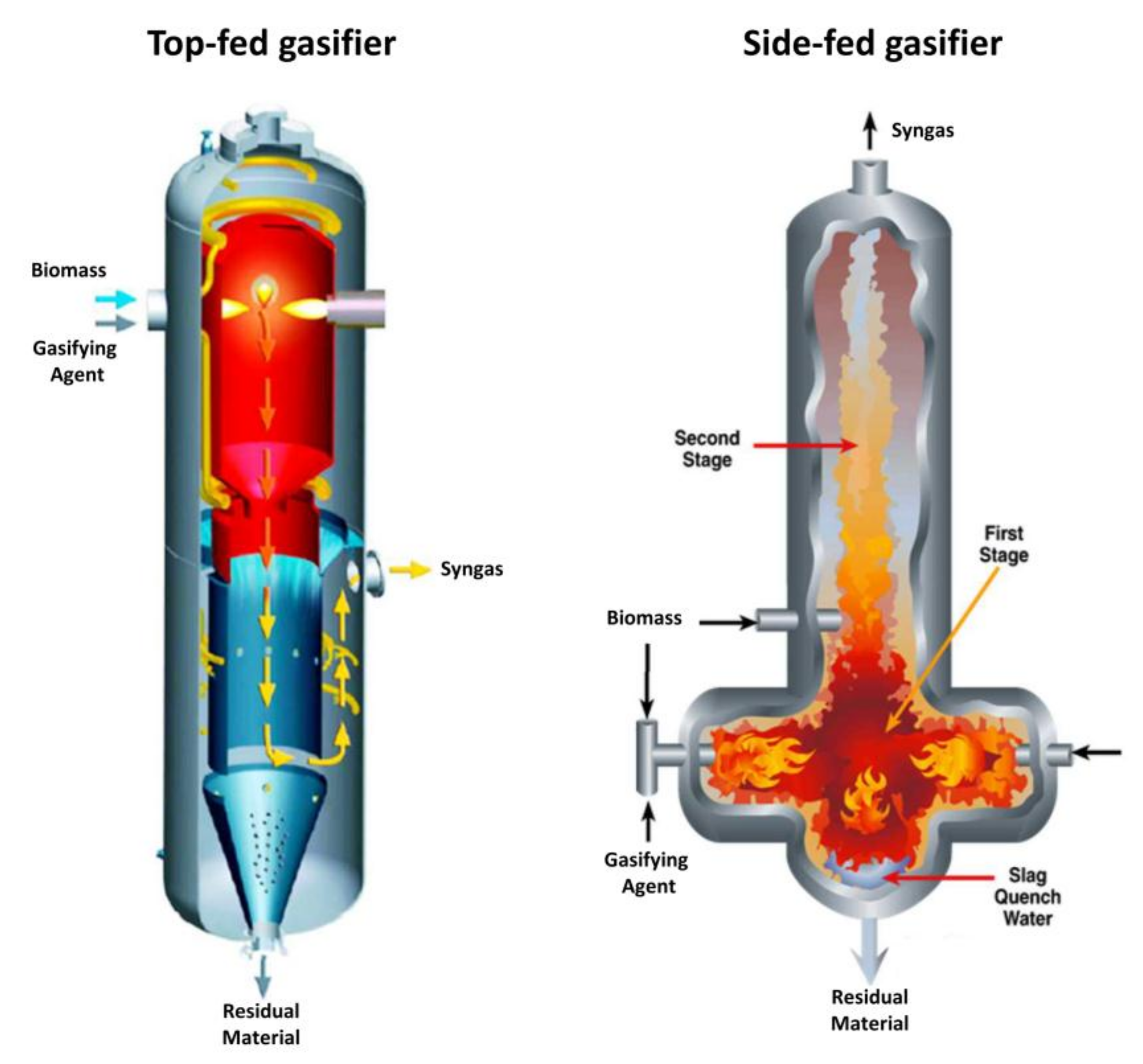
2.2. Gasification Reactors
- H2 composition varies from a minimum of 1.6–3% v/v (biomass type = mesquite wood; gasification temperature ≅ 1150 °C; GA = air; ER = 2.7) to a maximum of 30–50% v/v (biomass type = cedar wood; gasification temperature = 650–950 °C; GA = oxygen; ER = 0–0.3);
- CO composition varies from a minimum of 13–21% v/v (biomass type = mesquite wood; gasification temperature ≅ 1150 °C; GA = air; ER = 2.7) to a maximum of 22–25% v/v (biomass type = cedar wood; gasification temperature = 650–950 °C; GA = oxygen; ER = 0–0.3);
- CO2 composition varies from a minimum of 9–12% v/v (biomass type = juniper wood; gasification temperature ≅ 1050 °C; GA = air; ER = 2.7) to a maximum of 25–30% v/v (biomass type = cedar wood; gasification temperature = 650–950 °C; GA = oxygen; ER = 0–0.3);
- CH4 composition varies from a minimum of 1.5–1.8% v/v (biomass type = juniper wood; gasification temperature ≅ 1050 °C; GA = air; ER = 2.7) to a maximum of 8–10% v/v (biomass type = cedar wood; gasification temperature = 650–950 °C; GA = oxygen; ER = 0–0.3);
- Higher Heating Value varies from a minimum of 2.4–3.5 MJ/Nm3 (biomass type = mesquite wood; gasification temperature ≅ 1150 °C; GA = air; ER = 2.7) to a maximum of 6.5–12.1% v/v (biomass type = cedar wood; gasification temperature = 650–950 °C; GA = oxygen; ER = 0–0.3).
- H2 composition varies from a minimum of 8–12% v/v (biomass type = wood waste; gasification temperature = 900–1050 °C; GA = air; ER = 0.20–0.35) to a maximum of ≅21% v/v (biomass type = eucalyptus wood; gasification temperature = 950 °C; GA = air (two-stage air and premixed air/gas supply); ER = 0.27);
- CO composition varies from a minimum of ≅14% v/v (biomass type = eucalyptus wood; gasification temperature = 950 °C; GA = air; ER = 0.27) to a maximum of ≅23% v/v (biomass type = hazelnut shells; gasification temperature = 1000 °C; GA = air; ER = 0.35);
- CO2 composition varies from a minimum of 5–8% v/v (biomass type = wood waste; gasification temperature = 900–1050 °C; GA = air; ER = 0.20–0.35) to a maximum of ≅11% v/v (biomass type = hazelnut shells; gasification temperature = 1000 °C; GA = air; ER = 0.35);
- CH4 composition varies from a minimum of 1–3% v/v (biomass type = wood waste; gasification temperature = 900–1050 °C; GA = air; ER = 0.20–0.35) to a maximum of ≅4% v/v (biomass type = hazelnut shells; gasification temperature = 1000 °C; GA = air; ER = 0.35);
- Higher Heating Value varies from a minimum of 4.5 MJ/Nm3 (biomass type = wood waste; gasification temperature = 900–1050 °C; GA = air; ER = 0.20–0.35) to a maximum of 6.5% v/v (biomass type = eucalyptus wood; gasification temperature = 950 °C; GA = air (two-stage air and premixed air/gas supply); ER = 0.27).
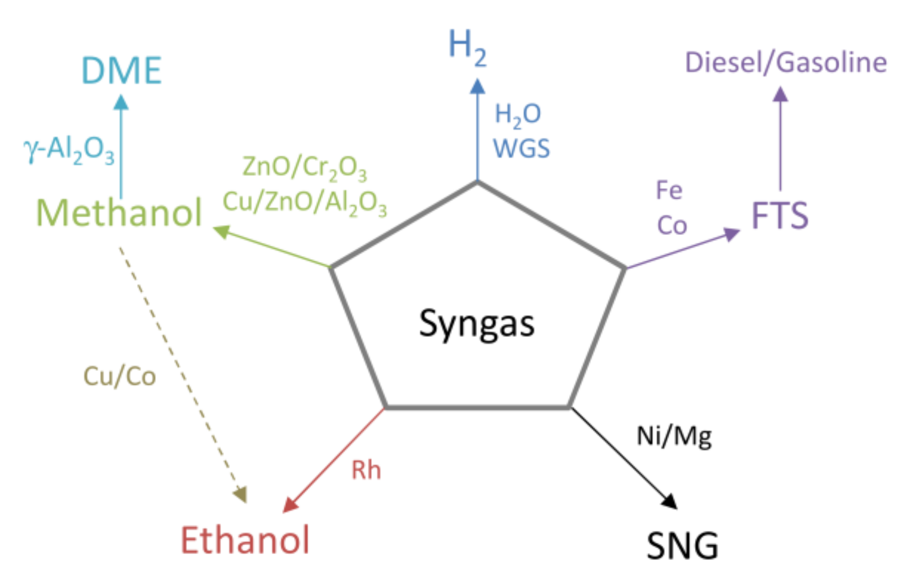
3. Biofuels from Syngas
3.1. Methanol
3.2. Ethanol
3.3. Dimethylether (DME)
3.4. Fischer-Tropsch Synthesis (FTS)
3.5. Hydrogen
3.6. Synthetic Natural Gas (SNG)
4. Conclusions
Author Contributions
Conflicts of Interest
References
- Naik, S.N.; Goud, V.V.; Rout, P.K.; Dalai, A.K. Production of first and second generation biofuels: A comprehensive review. Renew. Sustain. Energy Rev. 2010, 14, 578–597. [Google Scholar] [CrossRef]
- Reijnders, L. Conditions for the sustainability of biomass based fuel use. Energy Policy 2006, 34, 863–876. [Google Scholar] [CrossRef]
- Türe, S.; Uzun, D.; Türe, I.E. The potential use of sweet sorghum as a non-polluting source of energy. Energy 1997, 22, 17–19. [Google Scholar] [CrossRef]
- European Union. European Parliament Directive 2009/28/EC of the European Parliament and of the Council of 23 April 2009. Off. J. Eur. Union 2009, 140, 16–62. [Google Scholar] [CrossRef]
- USA Energy Independence. Security Act of 2007. Public Law 2007, 2007, 110–140. [Google Scholar]
- Molino, A.; Nanna, F.; Ding, Y.; Bikson, B.; Braccio, G. Biomethane production by anaerobic digestion of organic waste. Fuel 2013, 103, 1003–1009. [Google Scholar] [CrossRef]
- Molino, A.; Migliori, M.; Ding, Y.; Bikson, B.; Giordano, G.; Braccio, G. Biogas upgrading via membrane process: Modelling of pilot plant scale and the end uses for the grid injection. Fuel 2013, 107, 585–592. [Google Scholar] [CrossRef]
- Laursen, W. Students take a green initiative. Chem. Eng. 2005, 774–775, 32–34. [Google Scholar]
- Simpson-Holley, M.; Higson, A.; Evans, G. Bring on the biorefinery. Chem. Eng. 2007, 795, 46–49. [Google Scholar]
- Rajagopalan, S.; Datar, R.; Lewis, R.S. Formation of ethanol from carbon monoxide via a new microbial catalyst. Biomass Bioenergy 2002, 23, 487–493. [Google Scholar] [CrossRef]
- Eisberg, N. Harvesting energy. Chem. Ind. 2006, 17, 24–25. [Google Scholar] [CrossRef]
- Demirbas, A. Biofuels securing the planet’s future energy needs. Energy Convers. Manag. 2009, 50, 2239–2249. [Google Scholar] [CrossRef]
- He, J.; Zhang, W. Research on ethanol synthesis from syngas. J. Zhejiang Univ. A 2008, 9, 714–719. [Google Scholar] [CrossRef]
- Van der Drift, A.; Boerrigter, H. Synthesis gas from biomass for fuels and chemicals. In Proceedings of the SYNBIOS Conference Stock, Stockholm, Sweden, 18–20 May 2005; pp. 1–31. [Google Scholar]
- Drzyzga, O.; Revelles, O.; Durante-Rodríguez, G.; Díaz, E.; García, J.L.; Prieto, A. New challenges for syngas fermentation: Towards production of biopolymers. J. Chem. Technol. Biotechnol. 2015, 90, 1735–1751. [Google Scholar] [CrossRef]
- Molino, A.; Migliori, M.; Blasi, A.; Davoli, M.; Marino, T.; Chianese, S.; Catizzone, E.; Giordano, G. Municipal waste leachate conversion via catalytic supercritical water gasification process. Fuel 2017, 206, 155–161. [Google Scholar] [CrossRef]
- Sims, R.E.H.; Mabee, W.; Saddler, J.N.; Taylor, M. An overview of second generation biofuel technologies. Bioresour. Technol. 2010, 101, 1570–1580. [Google Scholar] [CrossRef] [PubMed]
- Stevens, C.; Roland Verhé, E. Renewable Bioresources: Scope and Modification for Non-Food Applications; John Wiley & Sons: Hoboken, NJ, USA, 2004; Volume 19, ISBN 0470021047. [Google Scholar]
- Baer, P.; Brown, M.A.; Kim, G. The job generation impacts of expanding industrial cogeneration. Ecol. Econ. 2015, 110, 141–153. [Google Scholar] [CrossRef]
- Molino, A.; Chianese, S.; Musmarra, D. Biomass gasification technology: The state of the art overview. J. Energy Chem. 2016, 25, 10–25. [Google Scholar] [CrossRef]
- Sikarwar, V.S.; Zhao, M.; Fennell, P.S.; Shah, N.; Anthony, E.J. Progress in biofuel production from gasification. Prog. Energy Combust. Sci. 2017, 61, 189–248. [Google Scholar] [CrossRef]
- Rauch, R.; Hrbek, J.; Hofbauer, H. Biomass gasification for synthesis gas production and applications of the syngas. Wiley Interdiscip. Rev. Energy Environ. 2014, 3, 343–362. [Google Scholar] [CrossRef]
- Bridgwater, A.V. Renewable fuels and chemicals by thermal processing of biomass. Chem. Eng. J. 2003, 91, 87–102. [Google Scholar] [CrossRef]
- Asadullah, M. Barriers of commercial power generation using biomass gasification gas: A review. Renew. Sustain. Energy Rev. 2014, 29, 201–215. [Google Scholar] [CrossRef]
- Ahmad, A.A.; Zawawi, N.A.; Kasim, F.H.; Inayat, A.; Khasri, A. Assessing the gasification performance of biomass: A review on biomass gasification process conditions, optimization and economic evaluation. Renew. Sustain. Energy Rev. 2016, 53, 1333–1347. [Google Scholar] [CrossRef]
- Molino, A.; Iovane, P.; Donatelli, A.; Braccio, G.; Chianese, S.; Musmarra, D. Steam gasification of refuse-derived fuel in a rotary kiln pilot plant: Experimental tests. Chem. Eng. Trans. 2013, 32, 337–342. [Google Scholar]
- Rodríguez-Olalde, N.E.; Mendoza-Chávez, E.; Castro-Montoya, A.J.; Saucedo-Luna, J.; Maya-Yescas, R.; Rutiaga-Quiñones, J.G.; Ponce Ortega, J.M. Simulation of syngas production from lignin using guaiacol as a model compound. Energies 2015, 8, 6705–6714. [Google Scholar] [CrossRef]
- IEA Task33 International Energy Agency (IEA) Bioenergy Task 33E—Thermal Gasification of Biomass Database. Available online: http://task33.ieabioenergy.com/# (accessed on 20 February 2018).
- Kumar, A.; Jones, D.D.; Hanna, M.A. Thermochemical biomass gasification: A review of the current status of the technology. Energies 2009, 2, 556–581. [Google Scholar] [CrossRef]
- De Lasa, H.; Salaices, E.; Mazumder, J.; Lucky, R. Catalytic steam gasification of biomass: Catalysts, thermodynamics and kinetics. Chem. Rev. 2011, 111, 5404–5433. [Google Scholar] [CrossRef] [PubMed]
- Udomsirichakorn, J.; Salam, P.A. Review of hydrogen-enriched gas production from steam gasification of biomass: The prospect of CaO-based chemical looping gasification. Renew. Sustain. Energy Rev. 2014, 30, 565–579. [Google Scholar] [CrossRef]
- Sikarwar, V.S.; Zhao, M.; Clough, P.; Yao, J.; Zhong, X.; Memon, M.Z.; Shah, N.; Anthony, E.J.; Fennell, P.S. An overview of advances in biomass gasification. Energy Environ. Sci. 2016, 9, 2939–2977. [Google Scholar] [CrossRef]
- Lange, J.P. Lignocellulose conversion: An introduction to chemistry, process and economics. Biofuels Bioprod. Biorefin. 2007, 1, 39–48. [Google Scholar] [CrossRef]
- Sansaniwal, S.K.; Rosen, M.A.; Tyagi, S.K. Global challenges in the sustainable development of biomass gasification: An overview. Renew. Sustain. Energy Rev. 2017, 80, 23–43. [Google Scholar] [CrossRef]
- Ramos, A.; Monteiro, E.; Silva, V.; Rouboa, A. Co-gasification and recent developments on waste-to-energy conversion: A review. Renew. Sustain. Energy Rev. 2018, 81, 380–398. [Google Scholar] [CrossRef]
- Göransson, K.; Söderlind, U.; He, J.; Zhang, W. Review of syngas production via biomass DFBGs. Renew. Sustain. Energy Rev. 2011, 15, 482–492. [Google Scholar] [CrossRef]
- Siedlecki, M.; de Jong, W.; Verkooijen, A.H.M. Fluidized bed gasification as a mature and reliable technology for the production of bio-syngas and applied in the production of liquid transportation fuels—A review. Energies 2011, 4, 389–434. [Google Scholar] [CrossRef]
- Parthasarathy, P.; Narayanan, K.S. Hydrogen production from steam gasification of biomass: Influence of process parameters on hydrogen yield—A review. Renew. Energy 2014, 66, 570–579. [Google Scholar] [CrossRef]
- Van de Velden, M.; Baeyens, J.; Brems, A.; Janssens, B.; Dewil, R. Fundamentals, kinetics and endothermicity of the biomass pyrolysis reaction. Renew. Energy 2010, 35, 232–242. [Google Scholar] [CrossRef]
- Farzad, S.; Mandegari, M.A.; Görgens, J.F. A critical review on biomass gasification, co-gasification, and their environmental assessments. Biofuel Res. J. 2016, 3, 483–495. [Google Scholar] [CrossRef]
- Sansaniwal, S.K.; Pal, K.; Rosen, M.A.; Tyagi, S.K. Recent advances in the development of biomass gasification technology: A comprehensive review. Renew. Sustain. Energy Rev. 2017, 72, 363–384. [Google Scholar] [CrossRef]
- Basu, P. Biomass Gasification and Pyrolysis Practical Design and Theory; Academic Press: Cambridge, MA, USA, 2010; ISBN 9780123749888. [Google Scholar]
- Lv, P.M.; Xiong, Z.H.; Chang, J.; Wu, C.Z.; Chen, Y.; Zhu, J.X. An experimental study on biomass air-steam gasification in a fluidized bed. Bioresour. Technol. 2004, 95, 95–101. [Google Scholar] [CrossRef] [PubMed]
- Luo, S.; Xiao, B.; Guo, X.; Hu, Z.; Liu, S.; He, M. Hydrogen-rich gas from catalytic steam gasification of biomass in a fixed bed reactor: Influence of particle size on gasification performance. Int. J. Hydrogen Energy 2009, 34, 1260–1264. [Google Scholar] [CrossRef]
- Hernández, J.J.; Aranda-Almansa, G.; Bula, A. Gasification of biomass wastes in an entrained flow gasifier: Effect of the particle size and the residence time. Fuel Process. Technol. 2010, 91, 681–692. [Google Scholar] [CrossRef]
- Jand, N.; Foscolo, P.U. Decomposition of wood particles in fluidized beds. Ind. Eng. Chem. Res. 2005, 44, 5079–5089. [Google Scholar] [CrossRef]
- Rapagn, S.; Mazziotti di Celso, G. Devolatilization of wood particles in a hot fluidized bed: Product yields and conversion rates. Biomass Bioenergy 2008, 32, 1123–1129. [Google Scholar] [CrossRef]
- Van der Drift, A.; Boerrigter, H.; Coda, B. Entrained Flow Gasification of Biomass—Ash Behaviour, Feeding Issues, and System Analyses; ECN-C-04-039; ECN: Petten, The Netherlands, 2004. [Google Scholar]
- Devi, L.; Ptasinski, K.J.; Janssen, F.J.J.G. A review of the primary measures for tar elimination in biomass gasification processes. Biomass Bioenergy 2002, 24, 125–140. [Google Scholar] [CrossRef]
- Ni, M.; Leung, D.Y.C.; Leung, M.K.H.; Sumathy, K. An overview of hydrogen production from biomass. Fuel Process. Technol. 2006, 87, 461–472. [Google Scholar] [CrossRef]
- Gil, J.; Aznar, M.P.; Caballero, M.A.; Francés, E.; Corella, J. Biomass Gasification in Fluidized Bed at Pilot Scale with Steam-Oxygen Mixtures. Product Distribution for Very Different Operating Conditions. Energy Fuels 1997, 11, 1109–1118. [Google Scholar] [CrossRef]
- Devi, L.; Ptasinski, K.J.; Janssen, F.J.J.G.; Van Paasen, S.V.B.; Bergman, P.C.A.; Kiel, J.H.A. Catalytic decomposition of biomass tars: Use of dolomite and untreated olivine. Renew. Energy 2005, 30, 565–587. [Google Scholar] [CrossRef]
- Sutton, D.; Kelleher, B.; Ross, J.R.H. Review of literature on catalysts for biomass gasification. Fuel Process. Technol. 2001, 73, 155–173. [Google Scholar] [CrossRef]
- Gómez-Barea, A.; Leckner, B.; Villanueva Perales, A.; Nilsson, S.; Fuentes Cano, D. Improving the performance of fluidized bed biomass/waste gasifiers for distributed electricity: A new three-stage gasification system. Appl. Therm. Eng. 2013, 50, 1453–1462. [Google Scholar] [CrossRef]
- Kirnbauer, F.; Wilk, V.; Hofbauer, H. Performance improvement of dual fluidized bed gasifiers by temperature reduction: The behavior of tar species in the product gas. Fuel 2013, 108, 534–542. [Google Scholar] [CrossRef]
- Abuadala, A.; Dincer, I. Investigation of a multi-generation system using a hybrid steam biomass gasification for hydrogen, power and heat. Int. J. Hydrogen Energy 2010, 35, 13146–13157. [Google Scholar] [CrossRef]
- Demirbas, A. Hydrogen-rich gases from biomass via pyrolysis and air-steam gasification. Energy Sources Part A 2009, 31, 1728–1736. [Google Scholar] [CrossRef]
- Wang, L.; Weller, C.L.; Jones, D.D.; Hanna, M.A. Contemporary issues in thermal gasification of biomass and its application to electricity and fuel production. Biomass Bioenergy 2008, 32, 573–581. [Google Scholar] [CrossRef]
- Knight, R.A. Experience with raw gas analysis from pressurized gasification of biomass. Biomass Bioenergy 2000, 18, 67–77. [Google Scholar] [CrossRef]
- Mathieu, P.; Dubuisson, R. Performance analysis of a biomass gasifier. Energy Convers. Manag. 2002, 43, 1291–1299. [Google Scholar] [CrossRef]
- Rapagnà, S.; Jand, N.; Kiennemann, A.; Foscolo, P.U. Steam-gasification of biomass in a fluidised-bed of olivine particles. Biomass Bioenergy 2000, 19, 187–197. [Google Scholar] [CrossRef]
- Lv, P.; Yuan, Z.; Ma, L.; Wu, C.; Chen, Y.; Zhu, J. Hydrogen-rich gas production from biomass air and oxygen/steam gasification in a downdraft Gasifier. Renew. Energy 2007, 32, 2173–2185. [Google Scholar] [CrossRef]
- Gil, J.; Corella, J.; Aznar, M.P.; Caballero, M.A. Biomass gasification in atmospheric and bubbling fluidized bed: Effect of the type of gasifying agent on the product distribution. Biomass Bioenergy 1999, 17, 389–403. [Google Scholar] [CrossRef]
- Zhou, J.; Chen, Q.; Zhao, H.; Cao, X.; Mei, Q.; Luo, Z.; Cen, K. Biomass-oxygen gasification in a high-temperature entrained-flow gasifier. Biotechnol. Adv. 2009, 27, 606–611. [Google Scholar] [CrossRef] [PubMed]
- Ruoppolo, G.; Miccio, F.; Brachi, P.; Picarelli, A.; Chirone, R. Fluidized bed gasification of biomass and biomass/coal pellets in oxygen and steam atmosphere. Chem. Eng. Trans. 2013, 32, 595–600. [Google Scholar] [CrossRef]
- Narvaez, I.; Orıo, A.; Aznar, M.P.; Corella, J. Biomass Gasification with Air in an Atmospheric Bubbling Fluidized Bed. Effect of Six Operational Variables on the Quality of produced raw gas. Ind. Eng. Chem. Res. 1996, 35, 2110–2120. [Google Scholar] [CrossRef]
- Kumar, A.; Eskridge, K.; Jones, D.D.; Hanna, M.A. Steam-air fluidized bed gasification of distillers grains: Effects of steam to biomass ratio, equivalence ratio and gasification temperature. Bioresour. Technol. 2009, 100, 2062–2068. [Google Scholar] [CrossRef] [PubMed]
- Hosseini, M.; Dincer, I.; Rosen, M.A. Steam and air fed biomass gasification: Comparisons based on energy and exergy. Int. J. Hydrog. Energy 2012, 37, 16446–16452. [Google Scholar] [CrossRef]
- Bhavanam, A.; Sastry, R.C. Biomass Gasification Processes in Downdraft Fixed Bed Reactors: A Review. Int. J. Chem. Eng. Appl. 2011, 2, 425–433. [Google Scholar] [CrossRef]
- Hanping, C.; Bin, L.; Haiping, Y.; Guolai, Y.; Shihong, Z. Experimental investigation of biomass gasification in a fluidized bed reactor. Energy Fuels 2008, 22, 3493–3498. [Google Scholar] [CrossRef]
- Palancar, M.C.; Serrano, M.; Aragón, J.M. Testing the technological feasibility of FLUMOV as gasifier. Powder Technol. 2009, 194, 42–50. [Google Scholar] [CrossRef]
- Wang, Z.; He, T.; Qin, J.; Wu, J.; Li, J.; Zi, Z.; Liu, G.; Wu, J.; Sun, L. Gasification of biomass with oxygen-enriched air in a pilot scale two-stage gasifier. Fuel 2015, 150, 386–393. [Google Scholar] [CrossRef]
- Hamad, M.A.; Radwan, A.M.; Heggo, D.A.; Moustafa, T. Hydrogen rich gas production from catalytic gasification of biomass. Renew. Energy 2016, 85, 1290–1300. [Google Scholar] [CrossRef]
- Sharma, S.; Sheth, P.N. Air-steam biomass gasification: Experiments, modeling and simulation. Energy Convers. Manag. 2016, 110, 307–318. [Google Scholar] [CrossRef]
- Pindoria, R.; Megaritis, A.; Herod, A.; Kandiyoti, R. A two-stage fixed-bed reactor for direct hydrotreatment of volatiles from the hydropyrolysis of biomass: Effect of catalyst temperature, pressure and catalyst ageing time on product characteristics. Fuel 1998, 77, 1715–1726. [Google Scholar] [CrossRef]
- Hein, D.; Karl, J. Conversion of biomass to heat and electricity. In Landolt-Börnstein Numerical Data and Functional Relationships in Science and Technology; Springer: Berlin, Germany, 2006; pp. 374–413. [Google Scholar]
- Franco, C.; Pinto, F.; Gulyurtlu, I.; Cabrita, I. The study of reactions influencing the biomass steam gasification process. Fuel 2003, 82, 835–842. [Google Scholar] [CrossRef]
- Gañan, J.; Abdulla, A.A.K.; Miranda, A.B.; Turegano, J.; Correia, S.; Cuerda, E.M. Energy production by means of gasification process of residuals sourced in Extremadura (Spain). Renew. Energy 2005, 30, 1759–1769. [Google Scholar] [CrossRef]
- Aqsha, A.; Tijani, M.M.; Moghtaderi, B.; Mahinpey, N. Catalytic pyrolysis of straw biomasses (wheat, flax, oat and barley) and the comparison of their product yields. J. Anal. Appl. Pyrolysis 2017, 125, 201–208. [Google Scholar] [CrossRef]
- Miranda, M.T.; Arranz, J.I.; Román, S.; Rojas, S.; Montero, I.; López, M.; Cruz, J.A. Characterization of grape pomace and pyrenean OAK pellets. Fuel Process. Technol. 2011, 92, 278–283. [Google Scholar] [CrossRef]
- Serrano, C.; Monedero, E.; Lapuerta, M.; Portero, H. Effect of moisture content, particle size and pine addition on quality parameters of barley straw pellets. Fuel Process. Technol. 2011, 92, 699–706. [Google Scholar] [CrossRef]
- Roy, M.M.; Corscadden, K.W. An experimental study of combustion and emissions of biomass briquettes in a domestic wood stove. Appl. Energy 2012, 99, 206–212. [Google Scholar] [CrossRef]
- Sharara, M.A.; Holeman, N.; Sadaka, S.S.; Costello, T.A. Pyrolysis kinetics of algal consortia grown using swine manure wastewater. Bioresour. Technol. 2014, 169, 658–666. [Google Scholar] [CrossRef] [PubMed]
- Yang, X.; Wang, H.; Strong, P.J.; Xu, S.; Liu, S.; Lu, K.; Sheng, K.; Guo, J.; Che, L.; He, L.; et al. Thermal properties of biochars derived from Waste biomass generated by agricultural and forestry sectors. Energies 2017, 10, 469. [Google Scholar] [CrossRef]
- Gillespie, G.D.; Everard, C.D.; Fagan, C.C.; McDonnell, K.P. Prediction of quality parameters of biomass pellets from proximate and ultimate analysis. Fuel 2013, 111, 771–777. [Google Scholar] [CrossRef]
- Font Palma, C. Modelling of tar formation and evolution for biomass gasification: A review. Appl. Energy 2013, 111, 129–141. [Google Scholar] [CrossRef]
- Bergman, P.C.; Veringa, H.J. Combined Torrefaction and Pelletisation; ECN: Petten, The Netherlands, 2005. [Google Scholar]
- Mohammed, M.A.A.; Salmiaton, A.; Wan Azlina, W.A.K.G.; Mohammad Amran, M.S.; Fakhru’L-Razi, A. Air gasification of empty fruit bunch for hydrogen-rich gas production in a fluidized-bed reactor. Energy Convers. Manag. 2011, 52, 1555–1561. [Google Scholar] [CrossRef]
- Li, J.; Yin, Y.; Zhang, X.; Liu, J.; Yan, R. Hydrogen-rich gas production by steam gasification of palm oil wastes over supported tri-metallic catalyst. Int. J. Hydrogen Energy 2009, 34, 9108–9115. [Google Scholar] [CrossRef]
- Chang, A.C.C.; Chang, H.F.; Lin, F.J.; Lin, K.H.; Chen, C.H. Biomass gasification for hydrogen production. Int. J. Hydrogen Energy 2011, 36, 14252–14260. [Google Scholar] [CrossRef]
- Skoulou, V.; Zabaniotou, A.; Stavropoulos, G.; Sakelaropoulos, G. Syngas production from olive tree cuttings and olive kernels in a downdraft fixed-bed gasifier. Int. J. Hydrogen Energy 2008, 33, 1185–1194. [Google Scholar] [CrossRef]
- Aljbour, S.H.; Kawamoto, K. Bench-scale gasification of cedar wood—Part I: Effect of operational conditions on product gas characteristics. Chemosphere 2013, 90, 1495–1500. [Google Scholar] [CrossRef] [PubMed]
- Aljbour, S.H.; Kawamoto, K. Bench-scale gasification of cedar wood—Part II: Effect of Operational conditions on contaminant release. Chemosphere 2013, 90, 1501–1507. [Google Scholar] [CrossRef] [PubMed]
- Chen, W.; Annamalai, K.; Ansley, R.J.; Mirik, M. Updraft fixed bed gasification of mesquite and juniper wood samples. Energy 2012, 41, 454–461. [Google Scholar] [CrossRef]
- Heidenreich, S.; Foscolo, P.U. New concepts in biomass gasification. Prog. Energy Combust. Sci. 2015, 46, 72–95. [Google Scholar] [CrossRef]
- Iribarren, D.; Susmozas, A.; Petrakopoulou, F.; Dufour, J. Environmental and exergetic evaluation of hydrogen production via lignocellulosic biomass gasification. J. Clean. Prod. 2014, 69, 165–175. [Google Scholar] [CrossRef]
- Rajvanshi, A. Biomass Gasification. In Alternative Energy in Agriculture; CRC Press: Boca Raton, FL, USA, 1986; ISBN 0-8493-6348-9. [Google Scholar]
- McKendry, P. Energy production from biomass (part 3): Gasification technologies. Bioresour. Technol. 2002, 83, 55–63. [Google Scholar] [CrossRef]
- Sheth, P.N.; Babu, B.V. Experimental studies on producer gas generation from wood waste in a downdraft biomass gasifier. Bioresour. Technol. 2009, 100, 3127–3133. [Google Scholar] [CrossRef] [PubMed]
- Olgun, H.; Ozdogan, S.; Yinesor, G. Results with a bench scale downdraft biomass gasifier for agricultural and forestry residues. Biomass Bioenergy 2011, 35, 572–580. [Google Scholar] [CrossRef]
- Jaojaruek, K.; Jarungthammachote, S.; Gratuito, M.K.B.; Wongsuwan, H.; Homhual, S. Experimental study of wood downdraft gasification for an improved producer gas quality through an innovative two-stage air and premixed air/gas supply approach. Bioresour. Technol. 2011, 102, 4834–4840. [Google Scholar] [CrossRef] [PubMed]
- Jordan, C.A.; Akay, G. Occurrence, composition and dew point of tars produced during gasification of fuel cane bagasse in a downdraft gasifier. Biomass Bioenergy 2012, 42, 51–58. [Google Scholar] [CrossRef]
- Koppatz, S.; Pfeifer, C.; Rauch, R.; Hofbauer, H.; Marquard-Moellenstedt, T.; Specht, M. H2 rich product gas by steam gasification of biomass with in situ CO2 absorption in a dual fluidized bed system of 8 MW fuel input. Fuel Process. Technol. 2009, 90, 914–921. [Google Scholar] [CrossRef]
- Miccio, F.; Piriou, B.; Ruoppolo, G.; Chirone, R. Biomass gasification in a catalytic fluidized reactor with beds of different materials. Chem. Eng. J. 2009, 154, 369–374. [Google Scholar] [CrossRef]
- Bartels, M.; Lin, W.; Nijenhuis, J.; Kapteijn, F.; van Ommen, J.R. Agglomeration in fluidized beds at high temperatures: Mechanisms, detection and prevention. Prog. Energy Combust. Sci. 2008, 34, 633–666. [Google Scholar] [CrossRef]
- Ruoppolo, G.; Miccio, F.; Chirone, R. Fluidized bed cogasification of wood and coal adopting primary catalytic method for tar abatement. Energy Fuels 2010, 24, 2034–2041. [Google Scholar] [CrossRef]
- Miccio, F.; Picarelli, A.; Ruoppolo, G. Increasing tar and hydrocarbons conversion by catalysis in bubbling fluidized bed gasifiers. Fuel Process. Technol. 2016, 141, 31–37. [Google Scholar] [CrossRef]
- Vaccaro, S.; Musmarra, D.; Petrecca, M. A technique for measurement of the jet penetration height in fluidized beds by pressure signal analysis. Powder Technol. 1997, 92, 223–231. [Google Scholar] [CrossRef]
- Song, T.; Wu, J.; Shen, L.; Xiao, J. Experimental investigation on hydrogen production from biomass gasification in interconnected fluidized beds. Biomass Bioenergy 2012, 36, 258–267. [Google Scholar] [CrossRef]
- Meng, X.; de Jong, W.; Fu, N.; Verkooijen, A.H.M. Biomass gasification in a 100 kWth steam-oxygen blown circulating fluidized bed gasifier: Effects of operational conditions on product gas distribution and tar formation. Biomass Bioenergy 2011, 35, 2910–2924. [Google Scholar] [CrossRef]
- Ngo, S.I.; Nguyen, T.D.B.; Lim, Y.; Song, B.H.; Lee, U.D.; Choi, Y.T.; Song, J.H. Performance evaluation for dual circulating fluidized-bed steam gasifier of biomass using quasi-equilibrium three-stage gasification model. Appl. Energy 2011, 88, 5208–5220. [Google Scholar] [CrossRef]
- Loha, C.; Gu, S.; De Wilde, J.; Mahanta, P.; Chatterjee, P.K. Advances in mathematical modeling of fluidized bed gasification. Renew. Sustain. Energy Rev. 2014, 40, 688–715. [Google Scholar] [CrossRef]
- Wang, P.; Massoudi, M. Slag behavior in gasifiers. Part I: Influence of coal properties and gasification conditions. Energies 2013, 6, 784–806. [Google Scholar] [CrossRef]
- Briesemeister, L.; Kremling, M.; Fendt, S.; Spliethoff, H. Air-Blown Entrained-Flow Gasification of Biomass: Influence of Operating Conditions on Tar Generation. Energy Fuels 2017, 31, 10924–10932. [Google Scholar] [CrossRef]
- Prins, M.J.; Ptasinski, K.J.; Janssen, F.J.J.G. More efficient biomass gasification via torrefaction. Energy 2006, 31, 3458–3470. [Google Scholar] [CrossRef]
- Couhert, C.; Salvador, S.; Commandr, J.M. Impact of torrefaction on syngas production from wood. Fuel 2009, 88, 2286–2290. [Google Scholar] [CrossRef]
- Brachi, P.; Chirone, R.; Miccio, F.; Miccio, M.; Ruoppolo, G. Entrained-flow gasification of torrefied tomato peels: Combining torrefaction experiments with chemical equilibrium modeling for gasification. Fuel 2018, 220, 744–753. [Google Scholar] [CrossRef]
- Kajitani, S.; Zhang, Y.; Umemoto, S.; Ashizawa, M.; Hara, S. Co-gasification reactivity of coal and woody biomass in high-temperature gasification. Energy Fuels 2010, 24, 145–151. [Google Scholar] [CrossRef]
- Hernández, J.J.; Aranda-Almansa, G.; Serrano, C. Co-gasification of biomass wastes and coal-coke blends in an entrained flow gasifier: An experimental study. Energy Fuels 2010, 24, 2479–2488. [Google Scholar] [CrossRef]
- Valero, A.; Usón, S. Oxy-co-gasification of coal and biomass in an integrated gasification combined cycle (IGCC) power plant. Energy 2006, 31, 1643–1655. [Google Scholar] [CrossRef]
- National Energy Technology Laboratory Commercial Gasifiers. Available online: https://www.netl.doe.gov/research/coal/energy-systems/gasification/gasifipedia/fmb (accessed on 29 January 2018).
- González-Vázquez, M.P.; García, R.; Pevida, C.; Rubiera, F. Optimization of a bubbling fluidized bed plant for low-temperature gasification of biomass. Energies 2017, 10, 306. [Google Scholar] [CrossRef]
- Gómez-Barea, A.; Leckner, B. Estimation of gas composition and char conversion in a fluidized bed biomass gasifier. Fuel 2013, 107, 419–431. [Google Scholar] [CrossRef]
- Demirbas, A. Competitive liquid biofuels from biomass. Appl. Energy 2011, 88, 17–28. [Google Scholar] [CrossRef]
- Demirbas, A. Progress and recent trends in biofuels. Prog. Energy Combust. Sci. 2007, 33, 1–18. [Google Scholar] [CrossRef]
- Matas Güell, B.; Sandquist, J.; Sørum, L. Gasification of Biomass to Second Generation Biofuels: A Review. J. Energy Resour. Technol. 2012, 135, 14001. [Google Scholar] [CrossRef]
- Lens, P.; Westermann, P.; Haberbauer, M.; Moreno, A. Biofuels for Fuel Cells: Renewable Energy from Biomass Fermentation; IWA Publishing: London, UK, 2005. [Google Scholar]
- Adachi, Y.; Komoto, M.; Watanabe, I.; Ohno, Y.; Fujimoto, K. Effective utilization of remote coal through dimethyl ether synthesis. Fuel 2000, 79, 229–234. [Google Scholar] [CrossRef]
- Sardesai, A.; Tartamella, T.; Lee, S. CO2/dimethyl ether (DME) feed mixtures in the DME-to-hydrocarbons (DTH) process. In Proceedings of the 12th Annual International Pittsburgh Coal Conference, Pittsburgh, PA, USA, 11–15 September 1995. [Google Scholar]
- Caldeira-Pires, A.; da Luz, S.M.; Palma-Rojas, S.; Rodrigues, T.O.; Silverio, V.C.; Vilela, F.; Barbosa, P.C.; Alves, A.M. Sustainability of the biorefinery industry for fuel production. Energies 2013, 6, 329–350. [Google Scholar] [CrossRef]
- Spath, P.L.; Dayton, D.C. Preliminary Screening—Technical and Economic Assessment of Synthesis Gas to Fuels and Chemicals with Emphasis on the Potential for Biomass-Derived Syngas; National Renewable Energy Laboratory: Golden, CO, USA, 2003.
- Zhang, W. Automotive fuels from biomass via gasification. Fuel Process. Technol. 2010, 91, 866–876. [Google Scholar] [CrossRef]
- Sauciuc, A.; Abosteif, Z.; Weber, G.; Potetz, A.; Rauch, R.; Hofbauer, H.; Schaub, G.; Dumitrescu, L. Influence of operating conditions on the performance of biomass-based Fischer-Tropsch synthesis. Biomass Convers. Biorefin. 2012, 2, 253–263. [Google Scholar] [CrossRef]
- Ciferno, J.P.; Marano, J.J. Benchmarking Biomass Gasification Technologies for Fuels, Chemicals and Hydrogen Production; US Department of Energy, National Energy Technology Laboratory: Albany, OR, USA, 2002.
- Dowaki, K.; Genchi, Y. Life cycle inventory analysis on Bio-DME and/or Bio-MeOH products through BLUE tower process. Int. J. Life Cycle Assess. 2009, 14, 611–620. [Google Scholar] [CrossRef]
- Srinivas, S.; Malik, R.K.; Mahajani, S.M. Fischer-Tropsch synthesis using bio-syngas and CO2. Energy Sustain. Dev. 2007, 11, 66–71. [Google Scholar] [CrossRef]
- Riedel, T.; Schulz, H.; Schaub, G.; Jun, K.W.; Hwang, J.S.; Lee, K.W. Fischer-Tropsch on iron with H2/CO and H2/CO2 as synthesis gases: The episodes of formation of the Fischer-Tropsch regime and construction of the catalyst. Top. Catal. 2003, 26, 41–54. [Google Scholar] [CrossRef]
- Visconti, C.G.; Martinelli, M.; Falbo, L.; Fratalocchi, L.; Lietti, L. CO2 hydrogenation to hydrocarbons over Co and Fe-based Fischer-Tropsch catalysts. Catal. Today 2016, 277, 161–170. [Google Scholar] [CrossRef]
- Van der Heijden, H.; Ptasinski, K.J. Exergy analysis of thermochemical ethanol production via biomass gasification and catalytic synthesis. Energy 2012, 46, 200–210. [Google Scholar] [CrossRef]
- Phillips, S.; Jechura, J.; Dayton, D.; Eggeman, T. Thermochemical Ethanol via Indirect Gasification and Mixed Alcohol Synthesis of Lignocellulosic Biomass; National Renewable Energy Laboratory: Golden, CO, USA, 2007.
- Ateka, A.; Sánchez-Contador, M.; Ereña, J.; Aguayo, A.T.; Bilbao, J. Catalyst configuration for the direct synthesis of dimethyl ether from CO and CO2 hydrogenation on CuO-ZnO-MnO/SAPO-18 catalysts. In Reaction Kinetics, Mechanisms and Catalysis; Springer: Berlin, Germany, 2018. [Google Scholar]
- Saravanan, K.; Ham, H.; Tsubaki, N.; Bae, J.W. Recent progress for direct synthesis of dimethyl ether from syngas on the heterogeneous bifunctional hybrid catalysts. Appl. Catal. B Environ. 2017, 217, 494–522. [Google Scholar] [CrossRef]
- Woolcock, P.J.; Brown, R.C. A review of cleaning technologies for biomass-derived syngas. Biomass Bioenergy 2013, 52, 54–84. [Google Scholar] [CrossRef]
- Abdoulmoumine, N.; Adhikari, S.; Kulkarni, A.; Chattanathan, S. A review on biomass gasification syngas cleanup. Appl. Energy 2015, 155, 294–307. [Google Scholar] [CrossRef]
- Asadullah, M. Biomass gasification gas cleaning for downstream applications: A comparative critical review. Renew. Sustain. Energy Rev. 2014, 40, 118–132. [Google Scholar] [CrossRef]
- Nexant, I.; San Francisco, C.; Aden, N.T.M.A. Survey and Down-Selection of Acid Gas Removal Systems for the Thermochemical Conversion of Biomass to Ethanol with a Detailed Analysis of an MDEA System; National Renewable Energy Laboratory: Golden, CO, USA, 2009.
- Reyes Valle, C.; Villanueva Perales, A.L.; Vidal-Barrero, F.; Gómez-Barea, A. Techno-economic assessment of biomass-to-ethanol by indirect fluidized bed gasification: Impact of reforming technologies and comparison with entrained flow gasification. Appl. Energy 2013, 109, 254–266. [Google Scholar] [CrossRef]
- Fail, S.; Diaz, N.; Benedikt, F.; Kraussler, M.; Hinteregger, J.; Bosch, K.; Hackel, M.; Rauch, R.; Hofbauer, H. Wood gas processing to generate pure hydrogen suitable for PEM fuel cells. ACS Sustain. Chem. Eng. 2014, 2, 2690–2698. [Google Scholar] [CrossRef]
- Loipersböck, J.; Lenzi, M.; Rauch, R.; Hofbauer, H. Hydrogen production from biomass: The behavior of impurities over a CO shift unit and a biodiesel scrubber used as a gas treatment stage. Korean J. Chem. Eng. 2017, 34, 2198–2203. [Google Scholar] [CrossRef]
- Aldana, P.A.U.; Ocampo, F.; Kobl, K.; Louis, B.; Thibault-Starzyk, F.; Daturi, M.; Bazin, P.; Thomas, S.; Roger, A.C. Catalytic CO2 valorization into CH4 on Ni-based ceria-zirconia. Reaction mechanism by operando IR spectroscopy. Catal. Today 2013, 215, 201–207. [Google Scholar] [CrossRef]
- Wang, G.; Xu, S.; Wang, C.; Zhang, J.; Fang, Z. Desulfurization and tar reforming of biogenous syngas over Ni/olivine in a decoupled dual loop gasifier. Int. J. Hydrog. Energy 2017, 42, 15471–15478. [Google Scholar] [CrossRef]
- Haro, P.; Johnsson, F.; Thunman, H. Improved syngas processing for enhanced Bio-SNG production: A techno-economic assessment. Energy 2016, 101, 380–389. [Google Scholar] [CrossRef]
- Atsonios, K.; Kougioumtzis, M.A.; Panopoulos, K.D.; Kakaras, E. Alternative thermochemical routes for aviation biofuels via alcohols synthesis: Process modeling, techno-economic assessment and comparison. Appl. Energy 2015, 138, 346–366. [Google Scholar] [CrossRef]
- Tsubaki, N.; Ito, M.; Fujimoto, K. A New Method of Low-Temperature Methanol Synthesis. J. Catal. 2001, 197, 224–227. [Google Scholar] [CrossRef]
- Santangelo, D.L.O.; Ahón, V.R.R.; Costa, A.L.H. Optimization of methanol synthesis loops with quench reactors. Chem. Eng. Technol. 2008, 31, 1767–1774. [Google Scholar] [CrossRef]
- Kralj, A.K.; Glavič, P. Multi-criteria optimization in a methanol process. Appl. Therm. Eng. 2009, 29, 1043–1049. [Google Scholar] [CrossRef]
- Nagaraja, B.M.; Bulushev, D.A.; Beloshapkin, S.; Ross, J.R.H. The effect of potassium on the activity and stability of Ni-MgO-ZrO2 catalysts for the dry reforming of methane to give synthesis gas. Catal. Today 2011, 178, 132–136. [Google Scholar] [CrossRef]
- Supp, E. How to Produce Methanol from Coal; Springer: Berlin, Germany, 2013. [Google Scholar]
- Cybulski, A. Liquid-phase methanol synthesis: Catalysts, mechanism, kinetics, chemical equilibria, vapor-liquid equilibria, and modeling—A review. Catal. Rev. 1994, 36, 557–615. [Google Scholar] [CrossRef]
- Wang, L.; Yang, L.; Zhang, Y.; Ding, W.; Chen, S.; Fang, W.; Yang, Y. Promoting effect of an aluminum emulsion on catalytic performance of Cu-based catalysts for methanol synthesis from syngas. Fuel Process. Technol. 2010, 91, 723–728. [Google Scholar] [CrossRef]
- Zhang, X.; Zhong, L.; Guo, Q.; Fan, H.; Zheng, H.; Xie, K. Influence of the calcination on the activity and stability of the Cu/ZnO/Al2O3 catalyst in liquid phase methanol synthesis. Fuel 2010, 89, 1348–1352. [Google Scholar] [CrossRef]
- Guo, X.; Li, L.; Liu, S.; Bao, G.; Hou, W. Preparation of CuO/ZnO/Al2O3 catalysts for methanol synthesis using parallel-slurry-mixing method. J. Fuel Chem. Technol. 2007, 35, 329–333. [Google Scholar] [CrossRef]
- Meshkini, F.; Taghizadeh, M.; Bahmani, M. Investigating the effect of metal oxide additives on the properties of Cu/ZnO/Al2O3 catalysts in methanol synthesis from syngas using factorial experimental design. Fuel 2010, 89, 170–175. [Google Scholar] [CrossRef]
- Dybkjaer, I.; Christensen, T.S. Syngas for Large Scale Conversion of Natural Gas to Liquid Fuels. Stud. Surf. Sci. Catal. 2001, 136, 435–440. [Google Scholar]
- Larocca, V.; Molino, A.; Petrone, M.T.; Barisano, D.; Giordano, G.; Braccio, G. Synthesis of Methanol from Biomass-derived syngas: Modelling and sizing of a bench-scale reactor. Int. J. Energy Technol. 2010, 2, 1–7. [Google Scholar]
- Taherzadeh, M. Ethanol from Lignocelluloce: Physiological Effects of Inhibitors and Fermentation Strategies; Chalmers University of Technology: Gothenburg, Sweden, 1999. [Google Scholar]
- Ajanovic, A. Biofuels versus food production: Does biofuels production increase food prices? Energy 2011, 36, 2070–2076. [Google Scholar] [CrossRef]
- Zhang, Z.; Lohr, L.; Escalante, C.; Wetzstein, M. Food versus fuel: What do prices tell us? Energy Policy 2010, 38, 445–451. [Google Scholar] [CrossRef]
- Goldemberg, J. Ethanol for a Sustainable Energy Future. Science 2007, 315, 808–810. [Google Scholar] [CrossRef] [PubMed]
- Cleveland, C.J.; Hall, C.A.S.; Herendeen, R.A.; Hagens, N.; Costanza, R.; Mulder, K.; Lynd, L.; Greene, N.; Dale, B.; Laser, M.; et al. Energy Returns on Ethanol Production. Science 2006, 312, 1746–1748. [Google Scholar] [CrossRef] [PubMed]
- Choi, Y.M.; Liu, P. Mechanism of ethanol synthesis from syngas on Rh(111). J. Am. Chem. Soc. 2009, 131, 13054–13061. [Google Scholar] [CrossRef] [PubMed]
- Spivey, J.J.; Egbebi, A. Heterogeneous catalytic synthesis of ethanol from biomass-derived syngas. Chem. Soc. Rev. 2007, 36, 1514. [Google Scholar] [CrossRef] [PubMed]
- Haider, M.A.; Gogate, M.R.; Davis, R.J. Fe-promotion of supported Rh catalysts for direct conversion of syngas to ethanol. J. Catal. 2009, 261, 9–16. [Google Scholar] [CrossRef]
- Pan, X.; Fan, Z.; Chen, W.; Ding, Y.; Luo, H.; Bao, X. Enhanced ethanol production inside carbon-nanotube reactors containing catalytic particles. Nat. Mater. 2007, 6, 507–511. [Google Scholar] [CrossRef] [PubMed]
- Roberts, G.W.; Márquez, M.A.; McCutchen, M.S. Alcohol synthesis in a high-temperature slurry reactor. Catal. Today 1997, 36, 255–263. [Google Scholar] [CrossRef]
- Tien-Thao, N.; Zahedi-Niaki, M.H.; Alamdari, H.; Kaliaguine, S. Conversion of syngas to higher alcohols over nanosized LaCo0.7Cu0.3O3 perovskite precursors. Appl. Catal. A 2007, 326, 152–163. [Google Scholar] [CrossRef]
- Subramani, V.; Gangwal, S.K. A review of recent literature to search for an efficient catalytic process for the conversion of syngas to ethanol. Energy Fuels 2008, 22, 814–839. [Google Scholar] [CrossRef]
- Benito, M.; Sanz, J.L.; Isabel, R.; Padilla, R.; Arjona, R.; Daza, L. Bio-ethanol steam reforming: Insights on the mechanism for hydrogen production. J. Power Sources 2005, 151, 11–17. [Google Scholar] [CrossRef]
- Kulawska, M.; Skrzypek, J. Kinetics of the synthesis of higher aliphatic alcohols from syngas over a modified methanol synthesis catalyst. Chem. Eng. Process. 2001, 40, 33–40. [Google Scholar] [CrossRef]
- Goldemberg, J.; Johansson, T.B.; Reddy, A.K.N.; Williams, R.H. A global clean cooking fuel initiative. Energy Sustain. Dev. 2004, 8, 5–12. [Google Scholar] [CrossRef]
- Larson, E.D.; Yang, H. Dimethyl ether (DME) from coal as a household cooking fuel in China. Energy Sustain. Dev. 2004, 8, 115–126. [Google Scholar] [CrossRef]
- Gunda, A.; Tartamella, T.; Gogate, M.; Lee, S. Dimethyl ether synthesis from CO2-rich syngas in the LPDME process. Fuel Energy Abstr. 1997, 38, 75. [Google Scholar]
- Ramos, F.S.; Farias, A.M.D.; Borges, L.E.P.; Monteiro, J.L.; Fraga, M.A.; Sousa-Aguiar, E.F.; Appel, L.G. Role of dehydration catalyst acid properties on one-step DME synthesis over physical mixtures. Catal. Today 2005, 101, 39–44. [Google Scholar] [CrossRef]
- Sai Prasad, P.S.; Bae, J.W.; Kang, S.H.; Lee, Y.J.; Jun, K.W. Single-step synthesis of DME from syngas on Cu-ZnO-Al2O3/zeolite bifunctional catalysts: The superiority of ferrierite over the other zeolites. Fuel Process. Technol. 2008, 89, 1281–1286. [Google Scholar] [CrossRef]
- Bae, J.W.; Kang, S.H.; Lee, Y.J.; Jun, K.W. Synthesis of DME from syngas on the bifunctional Cu-ZnO-Al2O3/Zr-modified ferrierite: Effect of Zr content. Appl. Catal. B Environ. 2009, 90, 426–435. [Google Scholar] [CrossRef]
- Gao, Z.; Huang, W.; Yin, L.; Xie, K. Liquid-phase preparation of catalysts used in slurry reactors to synthesize dimethyl ether from syngas: Effect of heat-treatment atmosphere. Fuel Process. Technol. 2009, 90, 1442–1446. [Google Scholar] [CrossRef]
- Galvita, V.V.; Semin, G.L.; Belyaev, V.D.; Yurieva, T.M.; Sobyanin, V.A. Production of hydrogen from dimethyl ether. Appl. Catal. A 2001, 216, 85–90. [Google Scholar] [CrossRef]
- Ogawa, T.; Inoue, N.; Shikada, T.; Ohno, Y. Direct Dimethyl Ether Synthesis. J. Nat. Gas Chem. 2003, 12, 219–227. [Google Scholar]
- Sunde, K.; Brekke, A.; Solberg, B. Environmental impacts and costs of hydrotreated vegetable oils, transesterified lipids andwoody BTL-A review. Energies 2011, 4, 845–877. [Google Scholar] [CrossRef]
- Ohno, Y. Recent Situation and Future Development of DME Direct Synthesis Technology; Japan DME Forum: Tokyo, Japan, 2002. [Google Scholar]
- Demirbas, A. Global biodiesel strategies. Energy Educ. Sci. Technol. 2006, 17, 27–63. [Google Scholar]
- Tijmensen, M.J.A.; Faaij, A.P.C.; Hamelinck, C.N.; Van Hardeveld, M.R.M. Exploration of the possibilities for production of Fischer Tropsch liquids and power via biomass gasification. Biomass Bioenergy 2002, 23, 129–152. [Google Scholar] [CrossRef]
- Prins, M.J.; Ptasinski, K.J.; Janssen, F.J.J.G. Exergetic optimisation of a production process of Fischer-Tropsch fuels from biomass. Fuel Process. Technol. 2005, 86, 375–389. [Google Scholar] [CrossRef]
- Dry, M.E. Fischer-Tropsch reactions and the environment. Appl. Catal. A 1999, 189, 185–190. [Google Scholar] [CrossRef]
- Dry, M.E. High quality diesel via the Fischer-Tropsch process—A review. J. Chem. Technol. Biotechnol. 2002, 77, 43–50. [Google Scholar] [CrossRef]
- Demirbas, A. Recent advances in biomass conversion technologies. Energy Educ. Sci. Technol. 2000, 6, 77–83. [Google Scholar]
- Sie, S.T.; Krishna, R. Fundamentals and selection of advanced Fischer-Tropsch reactors. Appl. Catal. A 1999, 186, 55–70. [Google Scholar] [CrossRef]
- Ahn, V.R.; Costa, E.F.; Monteagudo, J.E.P.; Fontes, C.E.; Biscaia, E.C.; Lage, P.L.C. A comprehensive mathematical model for the Fischer-Tropsch synthesis in well-mixed slurry reactors. Chem. Eng. Sci. 2005, 60, 677–694. [Google Scholar] [CrossRef]
- Rapagna, S.; Jand, N.; Foscolo, P.U. Catalytic Gasification of Biomass Rich Gas to Produce. Int. J. Hydrogen Energy 1998, 23, 551–557. [Google Scholar] [CrossRef]
- Li, S.; Krishnamoorthy, S.; Li, A.; Meitzner, G.D.; Iglesia, E. Promoted Iron-Based Catalysts for the Fischer-Tropsch Synthesis: Design, Synthesis, Site Densities, and Catalytic Properties. J. Catal. 2002, 206, 202–217. [Google Scholar] [CrossRef]
- Schulz, H. Short history and present trends of Fischer-Tropsch synthesis. Appl. Catal. A 1999, 186, 3–12. [Google Scholar] [CrossRef]
- Abbasi, T.; Abbasi, S.A. “Renewable” hydrogen: Prospects and challenges. Renew. Sustain. Energy Rev. 2011, 15, 3034–3040. [Google Scholar] [CrossRef]
- Nikolaidis, P.; Poullikkas, A. A comparative overview of hydrogen production processes. Renew. Sustain. Energy Rev. 2017, 67, 597–611. [Google Scholar] [CrossRef]
- Sircar, S.; Golden, T.C. Purification of hydrogen by pressure swing adsorption. Sep. Sci. Technol. 2000, 35, 667–687. [Google Scholar] [CrossRef]
- Demirbas, A. Comparison of thermochemical conversion processes of biomass to hydrogen-rich gas mixtures. Energy Sources Part A 2016, 38, 2971–2976. [Google Scholar] [CrossRef]
- Saxena, R.C.; Seal, D.; Kumar, S.; Goyal, H.B. Thermo-chemical routes for hydrogen rich gas from biomass: A review. Renew. Sustain. Energy Rev. 2008, 12, 1909–1927. [Google Scholar] [CrossRef]
- Chianese, S.; Loipersböck, J.; Malits, M.; Rauch, R.; Hofbauer, H.; Molino, A.; Musmarra, D. Hydrogen from the high temperature water gas shift reaction with an industrial Fe/Cr catalyst using biomass gasification tar rich synthesis gas. Fuel Process. Technol. 2015, 132, 39–48. [Google Scholar] [CrossRef]
- Muller, S.; Kotik, J.; Proll, T.; Rauch, R.; Hofbauer, H. Hydrogen from biomass for industry—Biomass gasification for integration in refineries. In Proceedings of the International Conference Polygeneration Strategies, Wien, Austria, 30 August–1 September 2011. [Google Scholar]
- Stelmachowski, M.; Nowicki, L. Fuel from the synthesis gas-the role of process engineering. Appl. Energy 2003, 74, 85–93. [Google Scholar] [CrossRef]
- Choudhary, T.V.; Goodman, D.W. CO-free production of hydrogen via stepwise steam reforming of methane. J. Catal. 2000, 192, 316–321. [Google Scholar] [CrossRef]
- Chianese, S.; Fail, S.; Binder, M.; Rauch, R.; Hofbauer, H.; Molino, A.; Blasi, A.; Musmarra, D. Experimental investigations of hydrogen production from CO catalytic conversion of tar rich syngas by biomass gasification. Catal. Today 2016, 277, 182–191. [Google Scholar] [CrossRef]
- Soukup, G.; Pfeifer, C.; Kreuzeder, A.; Hofbauer, H. In situ CO2 capture in a dual fluidized bed biomass steam gasifier—Bed material and fuel variation. Chem. Eng. Technol. 2009, 32, 348–354. [Google Scholar] [CrossRef]
- Lu, Y.J.; Jin, H.; Guo, L.J.; Zhang, X.M.; Cao, C.Q.; Guo, X. Hydrogen production by biomass gasification in supercritical water with a fluidized bed reactor. Int. J. Hydrogen Energy 2008, 33, 6066–6075. [Google Scholar] [CrossRef]
- Molino, A.; Migliori, M.; Macrì, D.; Valerio, V.; Villone, A.; Nanna, F.; Iovane, P.; Marino, T. Glucose gasification in super-critical water conditions for both syngas production and green chemicals with a continuous process. Renew. Energy 2016, 91, 451–455. [Google Scholar] [CrossRef]
- Demirbaş, A. Hydrogen production from biomass via supercritical water extraction. Energy Sources 2005, 27, 1409–1417. [Google Scholar] [CrossRef]
- Gassner, M.; Maréchal, F. Thermo-economic optimisation of the polygeneration of synthetic natural gas (SNG), power and heat from lignocellulosic biomass by gasification and methanation. Energy Environ. Sci. 2012, 5, 5768. [Google Scholar] [CrossRef]
- Duret, A.; Friedli, C.; Maréchal, F. Process design of Synthetic Natural Gas (SNG) production using wood gasification. J. Clean. Prod. 2005, 13, 1434–1446. [Google Scholar] [CrossRef]
- Gassner, M.; Maréchal, F. Thermo-economic process model for thermochemical production of Synthetic Natural Gas (SNG) from lignocellulosic biomass. Biomass Bioenergy 2009, 33, 1587–1604. [Google Scholar] [CrossRef]
- Centi, G.; Perathoner, S. Opportunities and prospects in the chemical recycling of carbon dioxide to fuels. Catal. Today 2009, 148, 191–205. [Google Scholar] [CrossRef]
- Rönsch, S.; Schneider, J.; Matthischke, S.; Schlüter, M.; Götz, M.; Lefebvre, J.; Prabhakaran, P.; Bajohr, S. Review on methanation—From fundamentals to current projects. Fuel 2016, 166, 276–296. [Google Scholar] [CrossRef]
- Kuznecova, I.; Gusca, J. Property based ranking of CO and CO2 methanation catalysts. Energy Procedia 2017, 128, 255–260. [Google Scholar] [CrossRef]
- Molino, A.; Braccio, G. Synthetic natural gas SNG production from biomass gasification—Thermodynamics and processing aspects. Fuel 2015, 139, 425–429. [Google Scholar] [CrossRef]
- Mills, G.A.; Steffgen, F.W. Catalytic methanation. Catal. Rev. 1974, 8, 159–210. [Google Scholar] [CrossRef]
- Weatherbee, G.D.; Bartholomew, C.H. Hydrogenation of CO2 on group VIII metals. II. Kinetics and mechanism of CO2 hydrogenation on nickel. J. Catal. 1982, 77, 460–472. [Google Scholar] [CrossRef]
- Dayton, D. Review of the Literature on Catalytic Biomass Tar Destruction: Milestone Completion Report; National Renewable Energy Laboratory: Golden, CO, USA, 2002.
- Vitasari, C.R.; Jurascik, M.; Ptasinski, K.J. Exergy analysis of biomass-to-synthetic natural gas (SNG) process via indirect gasification of various biomass feedstock. Energy 2011, 36, 3825–3837. [Google Scholar] [CrossRef]


| Gasification Step | Reaction |
|---|---|
| Pyrolysis | |
| Oxidation | (Char Oxidation) |
| (Partial Oxidation) | |
| (Hydrogen Oxidation) | |
| Reduction | (Boudouard Reaction) |
| (Reforming of Char) | |
| (Water Gas Shift (WGS) Reaction) | |
| (Methanation Reaction) | |
| (Steam Reforming of Methane) | |
| (Dry Reforming of Methane) | |
| Tar Reforming | (Steam Reforming of Tar) |
| Feedstock Parameter | Observation |
|---|---|
| biomass type [32,34,38,39] |
|
| moisture content [25,32,34,35,40,41] |
|
| particle size [32,38,42,43,44,45,46,47,48] |
|
| ash content [24,31,32,34,37] |
|
| Gasification Parameter | Observation |
|---|---|
| bed material [32,36,49,50,51,52,53] |
|
| operating parameters [21,24,25,30,34,36,41,44,49,54,55,56,57,58,59] |
|
| GAs [21,24,38,41,42,60,61,62,63,64,65] |
|
| equivalence ratio (ER) [24,32,41,42,66,67,68,69,70,71,72,73] |
|
| steam to biomass ratio (SB) [25,30,35,37,38,42,66,74,75] |
|
| Biomass Type/Typology | Proximate Analysis (% w/w) | Elemental Analysis (% w/wdry) | HHV (MJ/kgdry) | |||||||
|---|---|---|---|---|---|---|---|---|---|---|
| Moisture | Ash | Volatile | Fixed Carbon | C | H | N | O | S | ||
| Shells * | 11–14 | 1–2 | 74–78 | 20–25 | 48–51 | 6 | 0.2–0.5 | 41–44 | 0.01–0.03 | 18–20 |
| Pruning ** | 7–25 | 0.5–4 | 70–85 | 12–20 | 45–49 | 5–6 | 0.1–0.8 | 36–44 | 0.01–0.08 | 16–18 |
| Straw *** | 7–12 | 5–15 | 67–76 | 16–18 | 41–47 | 5–6 | 0.3–6 | 36–44 | 0.04–0.2 | 15–18 |
| Dry Exhausted olive | 9 | 4 | 77 | 19 | 51 | 6 | 0.3 | 38 | 0.02 | 20 |
| Miscanthus | 4 | 5 | 71 | 19 | 45 | 5 | 0.5 | 40 | 0.08 | 18 |
| Pine | 12.0 | 0.5 | 71.5 | 16.0 | 51.6 | 4.9 | 0.9 | 42.6 | N.D.# | 20.2 |
| Holm-oak | 9.5 | 2.4 | 70.2 | 17.8 | 51.1 | 5.3 | 0.9 | 42.7 | N.D.# | 19.4 |
| Eucalyptus | 10.6 | 0.7 | 74.8 | 13.9 | 52.8 | 6.4 | 0.4 | 40.4 | N.D.# | 21.2 |
| Pine | 10.0 | 0.4 | 73.6 | 15.7 | 52.1 | 6.36 | 0.07 | 41.0 | 0.05 | 17.8 |
| Oak | 7.3 | 3.7 | 12.7 | 83.6 | 49.9 | 5.98 | 0.21 | 42.6 | 0.05 | 19.1 |
| Barley Straw | 2.7 | 4.4 | 75.6 | 17.3 | 42.9 | 5.53 | 0.56 | 45.5 | 0.25 | 16.2 |
| Hay | 9.3 | 4.2 | 86.5 | 17.9 | 45.5 | 6.1 | 1.14 | 39.2 | 0.16 | 17.2 |
| Miscanthus | 9.0 | 1.7 | 73.5 | 18.5 | 47.5 | 6.2 | 0.73 | 40.7 | 0.15 | 19.4 |
| Microalgae | 5.1 | 19.9 | 64.5 | 10.4 | 52.7 | 7.22 | 8.01 | 28.9 | 0.49 | 16.6 |
| Biomass Type | Biomass Composition (% w/w) | |||
|---|---|---|---|---|
| Cellulose | Hemicellulose | Lignin | Others | |
| Softwood | 41 | 24 | 28 | 7 |
| Hardwood | 39 | 35 | 20 | 7 |
| Wheat straw | 40 | 28 | 17 | 15 |
| Rice straw | 30 | 25 | 12 | 33 |
| Bagasse | 38 | 39 | 20 | 3 |
| Oak wood | 34.5 | 18.6 | 28 | - |
| Pine wood | 42.1 | 17.7 | 25 | - |
| Birch wood | 35.7 | 25.1 | 19.3 | - |
| Spruce wood | 41.1 | 20.9 | 28 | - |
| Sunflower seed hull | 26.7 | 18.4 | 27 | - |
| Coconut shell | 24.2 | 24.7 | 34.9 | - |
| Almond shell | 24.7 | 27 | 27.2 | - |
| Poultry litter | 27 | 17.8 | 11.3 | 20 |
| Deciduous plant | 42 | 25 | 21.5 | 11.5 |
| Coniferous plant | 42 | 26 | 30 | 2 |
| Willow plant | 50 | 19 | 25 | 6 |
| Larch plant | 26 | 27 | 35 | 12 |
| Biomass Type | Syngas Composition (% v/v) | LHV (MJ/Nm3) | GA | ER | SB | T (°C) | GR | |||
|---|---|---|---|---|---|---|---|---|---|---|
| CO | H2 | CH4 | CO2 | |||||||
| Empty Fruit Bunch | 21–36 | 10–38 | 5–14 | 10–65 | 7.5–15.5 | air | 0.15–0.35 | - | 700–1000 | FlB |
| Pine sawdust | 35–43 | 21–39 | 6–10 | 18–20 | 7.4–8.6 | air-steam | 0.22 | 2.7 | 700–900 | FlB |
| Bamboo | 23.5–30.6 % m/m | 6.6–8.1 % m/m | 4–5 % m/m | 59–63 % m/m | 1.6–1.9 | air | 0.4 | - | 400–600 | FlB |
| α-cellulose | 6.5–11.2 | 13.5–18.5 | 2.2–3.7 | 26.3–27.7 | 6.5–7.6 | air-steam | 0.27 | 0–1.5 | 800 | FlB |
| Empty Fruit Bunch | 32–45 | 18.3–27.4 | 12–15 | 16.6–36 | 12.3–15.3 | air | 0.15–0.35 | - | 850 | FlB |
| Bamboo | 23.5–30.6 % m/m (air); 36.1–40.3 % m/m (air-steam); | 6.6–8.16 % m/m (air);10.9–16.5 % m/m (air-steam); | N.A. | N.A. | N.A. | air & air-steam | 0.4 | 0:1; 1:1 | 400–600 | FlB |
| Palm oil wastes | 15–25 | 48–60 | 4–5 | 20–25 | 9.1–11.2 | steam | - | 1.3 | 750–900 | FiB |
| Palm oil wastes | 14–33 | 47–58 | 3–6 | 14–26 | 8.7–12 | steam | - | 0.67–2.67 | 800 | FiB |
| Olive kernel | 15–20% w/w | 20–30% w/w | 10–12% w/w | 40–55% w/w | 8.8–10.4 | air | 0.14–0.42 | - | 950 | FiB |
| Gasifier Type | Flows | Gasification Temperature [°C] | Cold Gas Efficiency § [%] | Char Conversion * [%] | Tar Content [g/Nm3] | |
|---|---|---|---|---|---|---|
| Biomass | GA | |||||
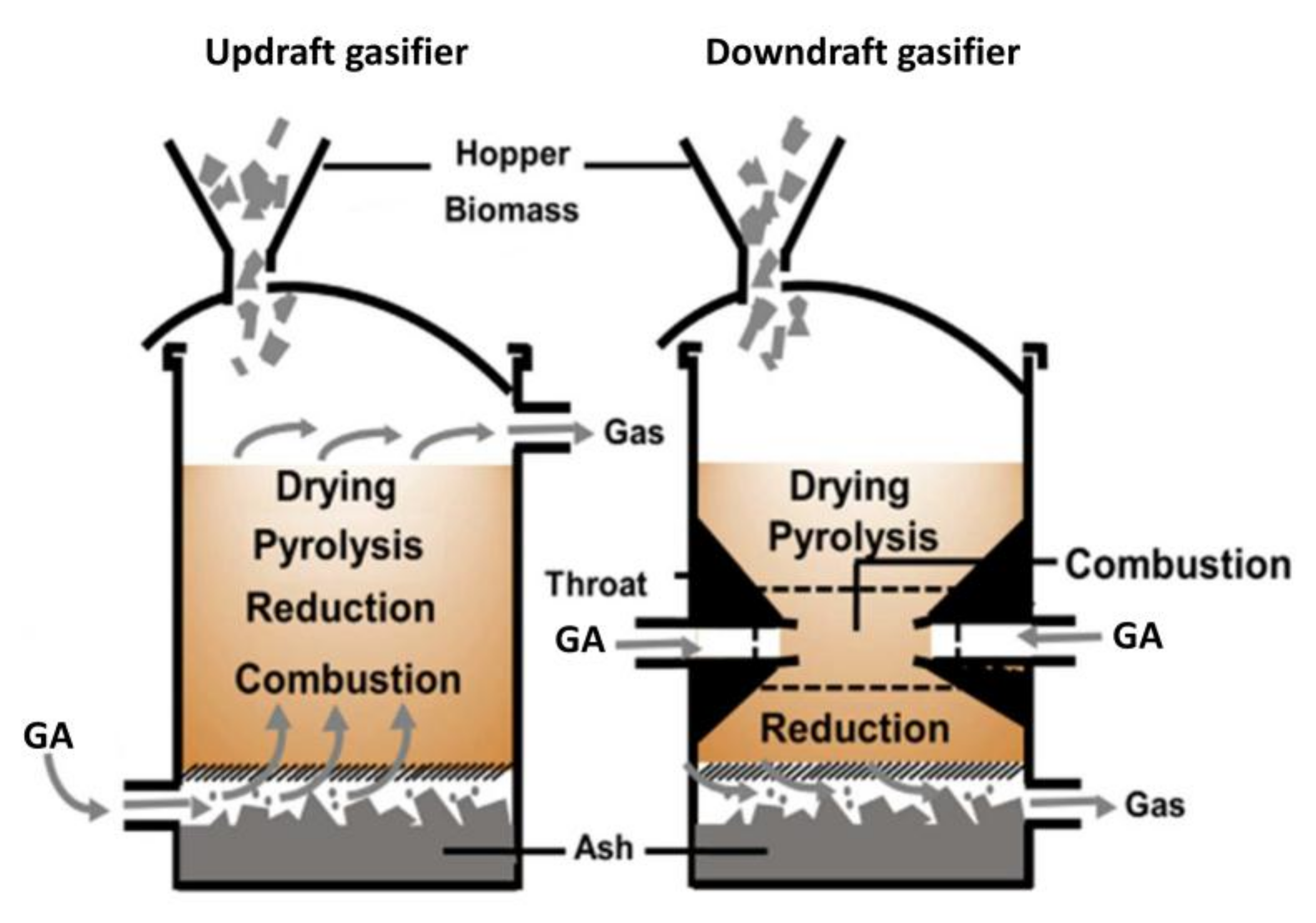
| Updraft gasifier | downward | upward | 950–1150 (max values) Syngas exit temperature: 150–400 | 20–60 | 40–85 | 1–150 |
| Downdraft gasifier | downward | downward | 900–1050 (max value) Syngas exit temperature: 700 | 30–60 | <85 | 0.015–1.5 |
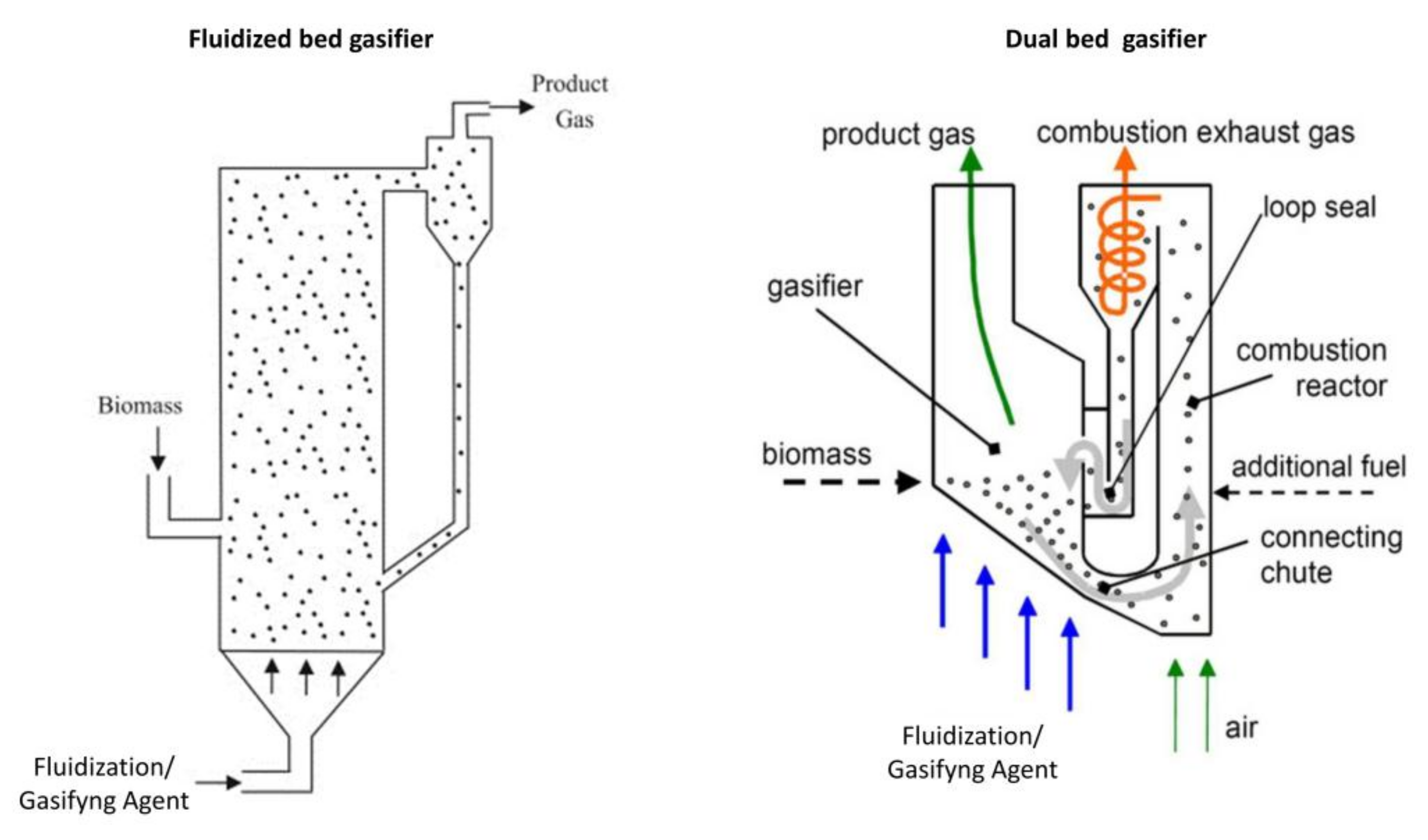
| Fluidized bed gasifier | upward | upward | 800–900 | <70 | <70 | 10–40 |
| Circulating fluidized bed gasifier | upward | upward | 750–850 | 50–70 | 70–95 | 5–12 |
| Entrained flow gasifier | downward | downward | 1300–1500 | 30–90 | 60–90 | ≅0–0.2 |
| Company/Institute/University Name | Start-Up Year | TRL-Scale | Fed | Output (Stream Flow) | Technology | Country |
|---|---|---|---|---|---|---|
| Cutec | 1990 | TRL 4–5 pilot | straw, wood, dried silage, organic residues | FT liquids (0.02 t/year) | Atmospheric gasifier | Germany |
| Lahti Energia Oy | 1998 | TRL 9 commercial | wood waste | renewable diesel (HVO) (70 MWth) | Circulating Fluidized Bed gasifier | Finland |
| CHP Agnion Biomasse Heizkraftwerk Pfaffenhofen * | 2001 | TRL 4–5 pilot | wood waste (80,000 t/year) | SNG (32.5 MWth) | Agnion Heatpipe-Reformer | Germany |
| Enerkem | 2003 | TRL 4–5 pilot | wood chips, treated wood, sludge, municipal solid waste, petroleum coke, spent plastics and wheat straw | SNG, ethanol (375 t/year), methanol (475 m3/year) | N.A | Canada |
| CHOREN Industries GmbH | 2003 | TRL 4–5 pilot | dry wood chips from recycled wood and residual forestry wood | FT liquids (53 t/year) | N.A. | Germany |
| Vienna University of Technology/BIOENERGY 2020+ | 2005 | TRL 4–5 pilot | syngas from FICFB gasifier (5 m3/h) | FT liquids (5 kg/day) | N.A. | Austria |
| Southern Research Institute ** | 2007 | TRL 4–5 pilot | cellulosic, municipal wastes, syngas (4 t/day) | FT liquids (0.002 t/year), mixed alcohols | N.A. | United States |
| West Biofuels | 2007 | TRL 6–7 demonstration | clean wood, waste wood (5 t/day) | FT liquids | Dual fluidized bed thermal reforming | United States |
| Bio SNG Guessin | 2008 | TRL 6–7 demonstration | syngas from gasifier (350 m3/year) | SNG (576 t/year) | N.A. | Austria |
| Enerkem | 2009 | TRL 6–7 demonstration | treated wood (i.e., decommissioned electricity poles, and railway ties), wood waste and MSW (48 t/day) | ethanol (4000 t/year), methanol (1000 t/year) | N.A | Canada |
| GTI Gas Technology Institute *** | 2009 | TRL 4–5 pilot | pellets, wood chips (24 t/day) | gasoline-type fuels (38 m3/year) | N.A | United States |
| H2Herten GmbH **** | 2009 | TRL 6–7 demonstration | roadside greenery/syngas (13 MW) | H2 (150 m3/h) | Multi-stage reforming process | Germany |
| Virent, Inc. | 2009 | TRL 6–7 demonstration | cane sugar, beet sugar, corn syrup, hydrolysates from cellulosic biomass including pine residues, sugarcane bagasse and corn stover | diesel-type hydrocarbons (30 t/year) | N.A. | United States |
| BioMCN | 2009 | TRL 8 first-of-a-kind commercial demo | crude glycerine, others | methanol (200,000 t/year) | N.A. | Netherlands |
| TUBITAK MRC—ENERGY INSTITUTE—TURKEY | 2009 | TRL 4–5 pilot | biomass | SNG (0.2 MW) | Down draft fixed bed gasifier | Turkey |
| Greasoline GmbH | 2011 | TRL 4–5 pilot | bio-based oils and fats, residues of plant oil processing, free fatty acids, used bio-based oils and fats (3 t/year) | diesel-type hydrocarbons (2 t/year) | Catalytic cracking of bio-based oils + fats primarily produces diesel fuel-range hydrocarbons | Germany |
| LTU Green Fuels | 2011 | TRL 4–5 pilot | black liquor/pyrolysis oil (co-gasif. with black liquor) | methanol (4 t/day), DME (4 t/day) | N.A. | Sweden |
| BioTfueL-consortium | 2012 | TRL 4–5 pilot | forest waste, straw, green waste, dedicated crops | FT liquids (60 t/year), jet fuel component | N.A | France |
| Karlsruhe Institute of Technology (KIT) | 2012 | TRL 4–5 pilot | straw (0.5 t/h) | gasoline-type fuels (608 t/year) | Fast pyrolysis, high pressure entrained flow gasification, hot gas cleaning, DME- and gasoline synthesis | Germany |
| INEOS New Planet BioEnergy ***** | 2012 | TRL 4–5 pilot | vegetative waste, MSW (300 t/day) | ethanol (3.469 m3/h) | N.A. | United States |
| TUBITAK | 2013 | TRL 4–5 pilot | combination of hazelnut shell, olive cake, wood chip and lignite blends (0.2 t/h) | FT liquids (250 t/year) | Pressurised fluidized bed gasifier | Turkey |
| Enerkem Alberta Biofuels LP | 2014 | TRL 8 first-of-a-kind commercial demo | post-sorted municipal solid waste (MSW) (100,000 t/year) | ethanol (30,000 t/year), methanol | N.A | Canada |
| Goteborg Energi AB | 2014 | TRL 6–7 demonstration | forest residues, wood pellets, branches and tree tops | SNG (11,200 t/year) | Repotec indirect gasification technology and Haldor Topsoe fixed bed methanation | Sweden |
| Karlsruhe Institute of Technology (KIT) | 2014 | TRL 6–7 demonstration | straw (0.5 t/h) | DME (608 t/year), gasoline-type fuels (360 t/year) | Fast pyrolysis, high pressure entrained flow gasification, hot gas cleaning, DME- and gasoline synthesis | Germany |
| BioMCN | 2017 | TRL 8 first-of-a-kind commercial demo | wood chips | methanol (413,000 t/year) | N.A. | Netherlands |
| Total | 2017 | TRL 6–7 demonstration | straw, forest waste, dedicated energy crops | FT liquids (200,000 t/year) | N.A. | France |
| Go Green Fuels Ltd. | 2018 | TRL 8 first-of-a-kind commercial demo | refuse derived fuel and waste wood (7500 t/year) | SNG (1500 t/year) | N.A. | United Kingdom |
| ECN | 2019 | TRL 6–7 demonstration | N.A. | SNG (300 MW) | N.A. | Netherlands |
| Fulcrum BioEnergy Sierra Biofuels Plant ****** | 2019 | TRL 9 commercial | waste (20,000 t/year) | FT liquids (314,913 t/year) | N.A. | United States |
| Red Rock Biofuels | 2019 | TRL 8 first-of-a-kind commercial demo | N.A. | diesel-type hydrocarbons (1 t/year) | N.A. | United States |
| Vanerco (Enerkem & Greenfield Ethanol) | 2019 | TRL 6–7 demonstration | N.A. | ethanol (30,000 t/year) | N.A. | Canada |
| Biofuel | Pressure (bar) | Temperature (°C) | Catalyst | H2/CO (mol/mol) | CO2 |
|---|---|---|---|---|---|
| methanol | 250–300 | 350–450 | ZnO/Cr2O3 | 3 | 4–8% v/v |
| 50–100 | 200–300 | Cu/ZnO/Al2O3 | 2 | ||
| ethanol + | 55–65 | 230–300 | Rh catalysts | 2 | <1–5 mol % |
| 70–105 | MoS2 or | ≅1–1.2 | <5 mol % | ||
| DME | methanol synthesis | methanol synthesis | γ-Al2O3 catalysts; methanol synthesis with additives | ≅1 | methanol synthesis; H2/CO2 = 3 §§,# |
| 30–70 | 200–300 | Bifunctional catalysts (CuO–ZnO–MnO and zeolite) | ≅2; 3 § | CO2/(CO + CO2) < 0.25 # | |
| FTS | 10–40 | 300–350 | Fe catalyst | 0.6–1.7; 2 * | H2/CO2 = 1 #; 3 #,* |
| 7–12 | 200–240 | Co catalyst | 2.0–2.15 | H2/CO2 = 3 # | |
| hydrogen | 1–30 | 200–1100 | Ni, Fe, Mo catalysts | ≥2 † | - |
| SNG | 1–25 | 200–450 | Ni (mainly), Co, Fe, Ru catalysts | ≥3 | H2/CO2 = 4 # |
| Contaminant | Syngas End Use | ||||
|---|---|---|---|---|---|
| Methanol Synthesis (mg/m3) | Ethanol + (ppmv) | FTS (ppmv) | hydrogen (ppmv) | SNG (ppmv) | |
| PM | <0.02 | 0 | 0 | 0 | 0 |
| Tars | <0.01 | <0.5 | <0.01 § | <1–2 ##; <2–5 ### | <2–5 ### |
| Alkali | <0.005 # | N.A. | <0.01 | N.A. | N.A. |
| Nitrogen | <0.1 | <1–10 | <0.02–10 | <1–10 | <30 |
| Sulphur | <0.5 #; <1 | <1–50; 50–100 ++ | <0.01–1 | <1–50; 50–100 ++ | <0.1 * |
| Halides | <0.001 #; <0.1 | N.A. | <0.01 | N.A. | <10 |
© 2018 by the authors. Licensee MDPI, Basel, Switzerland. This article is an open access article distributed under the terms and conditions of the Creative Commons Attribution (CC BY) license (http://creativecommons.org/licenses/by/4.0/).
Share and Cite
Molino, A.; Larocca, V.; Chianese, S.; Musmarra, D. Biofuels Production by Biomass Gasification: A Review. Energies 2018, 11, 811. https://doi.org/10.3390/en11040811
Molino A, Larocca V, Chianese S, Musmarra D. Biofuels Production by Biomass Gasification: A Review. Energies. 2018; 11(4):811. https://doi.org/10.3390/en11040811
Chicago/Turabian StyleMolino, Antonio, Vincenzo Larocca, Simeone Chianese, and Dino Musmarra. 2018. "Biofuels Production by Biomass Gasification: A Review" Energies 11, no. 4: 811. https://doi.org/10.3390/en11040811
APA StyleMolino, A., Larocca, V., Chianese, S., & Musmarra, D. (2018). Biofuels Production by Biomass Gasification: A Review. Energies, 11(4), 811. https://doi.org/10.3390/en11040811