1. Introduction
Wind energy plays a significant role in renewable energy power generation, and wind power generation is the most cost-effective climate change mitigation technology. For example, China’s cumulative installed wind power capacity reached 168.73 GW at the end of 2016 [
1]. There is no doubt that designing a wind power generator with high reliability, high power, and torque density as well as easy assembly is one of the key technologies in a wind power generation system. Nowadays, transverse flux permanent magnet generators (TFPMG) have received great attention for wind power applications, since they have the possibility to attain a high torque and power density due to the unique transverse flux in the magnetic circuit [
2].
Reviewing the development of the transverse flux permanent magnet (TFPM) machine, it was first proposed and named as such by Weh et al. in the 1980s [
3]. Its magnetic circuit is in a direction transverse to the direction of motion and the current flow [
4]. The major advantage of a TFPM machine compared to a radial flux machine and axial flux machine is the decoupling of magnetic and electric load. As a result, the magnetic and electric load can be set independently, which allows for higher torque and power density than the radial flux and axial flux permanent magnet (PM) machine. Moreover, due to the decoupling of magnetic and electric load, the TFPM machine in comparison with the radial flux machine and axial flux machine also has the more outstanding capability of having large pole numbers. Therefore, it can be used for low-speed, large-torque, direct-drive applications, such as wind power generation and wave energy generation [
5,
6,
7].
Thus, various TFPM machines with attractive structures have been proposed and studied in many areas [
8,
9,
10,
11]. For instance, flux-concentrated TFPM machines were proposed to obtain large torque density or power density [
12,
13,
14]. A novel TFPM machine with double coil was proposed to diminish magnetic flux leakage and reduce the machine’s weight [
15]. A novel TFPMG with staggered stator-hoop and surface-mounted rotor-disk was specially designed for a low-speed and large-torque wind power generator [
16]. A novel consequent-pole TFPM machine with E-core was proposed for improving PM utilization [
17]. TFPM machines with soft magnetic composite (SMC) materials were proposed to pursue better performance, such as reducing weight, reducing loss, and improving efficiency [
18,
19]. Reference [
20] investigated the existing TFPM machines with U-core that can be constructed as an outer rotor in-wheel motor which is suitable for low speed applications. Much work on cogging torque optimization of TFPM machines was provided in [
21,
22,
23,
24]. A 3D equivalent reluctance network model in [
25] and a 3D analytical magnetic charge model in [
26] were used to accurately analyze the performance of the TFPM machines. It can be found from [
8,
12,
13,
14,
15,
16,
17,
18,
19,
20,
21,
22,
23,
24,
25,
26] that C, U, E, and Z-shaped cores are common structures in TFPM machines. Their common point is that they are complete iron cores rather than a combination of many parts, for example, a U-shaped core is not made up of “two L-shaped cores”.
However, there are also some common drawbacks in many TFPM machines: (1) fabrication difficulty: due to the complex magnetic circuit with a large number of magnetic parts, it is difficult to fabricate the iron cores with laminated steel sheets [
18]; (2) low utilization of PMs: only half of the PMs do work at the same time [
27]; (3) low reliability: due to the PMs on the rotating part, the reliability of the rotor is low [
28]. In order to alleviate these problems, a novel transverse flux permanent magnet disk generator (TFPMDG) with U-shaped stator cores was proposed by J.S. Moghani et al. [
29]. This generator consists of two stator disk and a rotor disk. Each stator disk is formed by several modular stator cores with a U shape. The circular coils are placed on the stator. PMs are inserted in the rotor disk which is sandwiched by the two stator disks. It can offer a very compact and robust structure, and get rid of the fabrication difficulty arising from the lamination of the iron cores in traditional disk machines as well as improve the utilization of PMs.
Inspired by work presented in [
27,
28], and with the purpose of solving the existing problems mentioned above, this paper presents a novel transverse flux permanent magnet disk generator (TFPMDG). The main features of its structure are the modular H-shaped stator cores and two simple rotor disks. The machine structure is different from the structures previously introduced in the references. The main difference is that each H-shaped stator core is formed by two T-shaped iron cores and a PM rather than a complete H-shaped core, which makes the manufacturing simpler and easier. Each rotor disk consists of a rotor holder and several rotor bars, resulting in high robustness and reliability. Moreover, two circular coils in the H-shaped stator cores together with the stator disk are sandwiched by the two rotor disks, which can improve the utilization of PMs.
This paper is organized as follows. In
Section 2, the structure and principle of the proposed TFPMDG are introduced in detail. In
Section 3, the magnetic circuit method is used to analyze the TFPMDG. In
Section 4, the electromagnetic performance is analyzed by using the three-dimensional (3D) finite element method (FEM). Meanwhile, EMF optimization is carried out by changing the shape of the rotor bar. In
Section 5, a prototype is fabricated to verify the simulation results. Finally, the conclusions are drawn in
Section 6.
2. Structure and Operating Principle
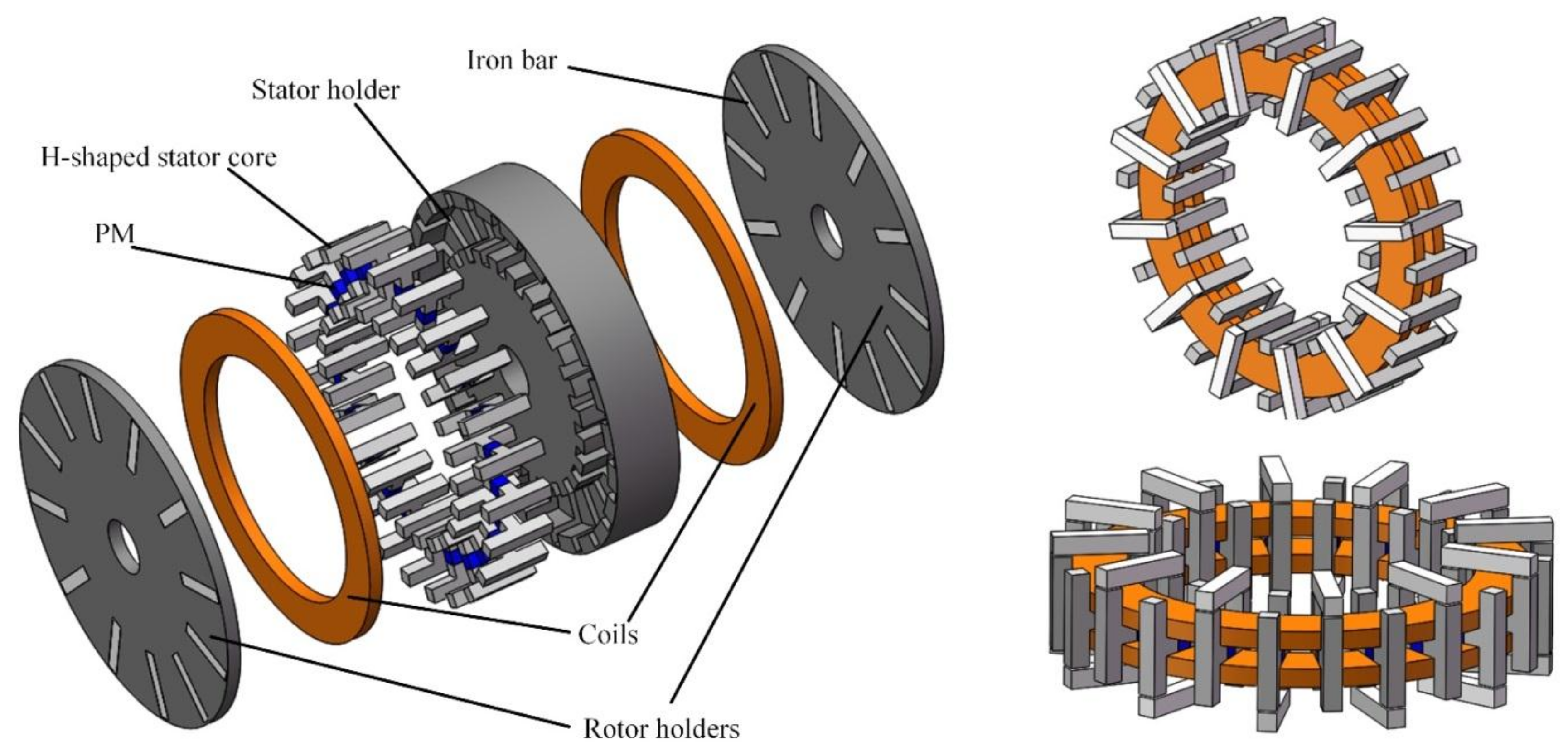
Figure 1 shows a single phase structure of the proposed TFPMDG. It consists of a stator disk and two rotor disks. The stator disk is sandwiched by the two rotor disks. The stator disk is composed of a stator holder and several modular H-shaped stator cores. Each H-shaped stator core is formed by two T-shaped iron cores and a PM, which will make the lamination of the stator core and assembly of the PM easy. Wherein, the PM in each H-shaped stator core is magnetized along the radial direction of the stator disk. The magnetized directions of PMs between two adjacent H-shaped stator cores are opposite. All of the H-shaped stator cores are symmetrically deployed in the stator holder, and, as a result, two annular grooves are naturally formed to accommodate two circular coils. As can be seen from
Figure 1, the structures of the two rotor disks are quite simple. Embedding iron bars in a rotor holder constitutes a rotor disk, which can improve the mechanical robustness of the rotor disk. It is worth noting that the iron bars in a rotor disk and the ones in another rotor disk are in a staggered arrangement along the circumference direction; moreover, the number of irons in a rotor disk is half number of the H-shaped stator cores.
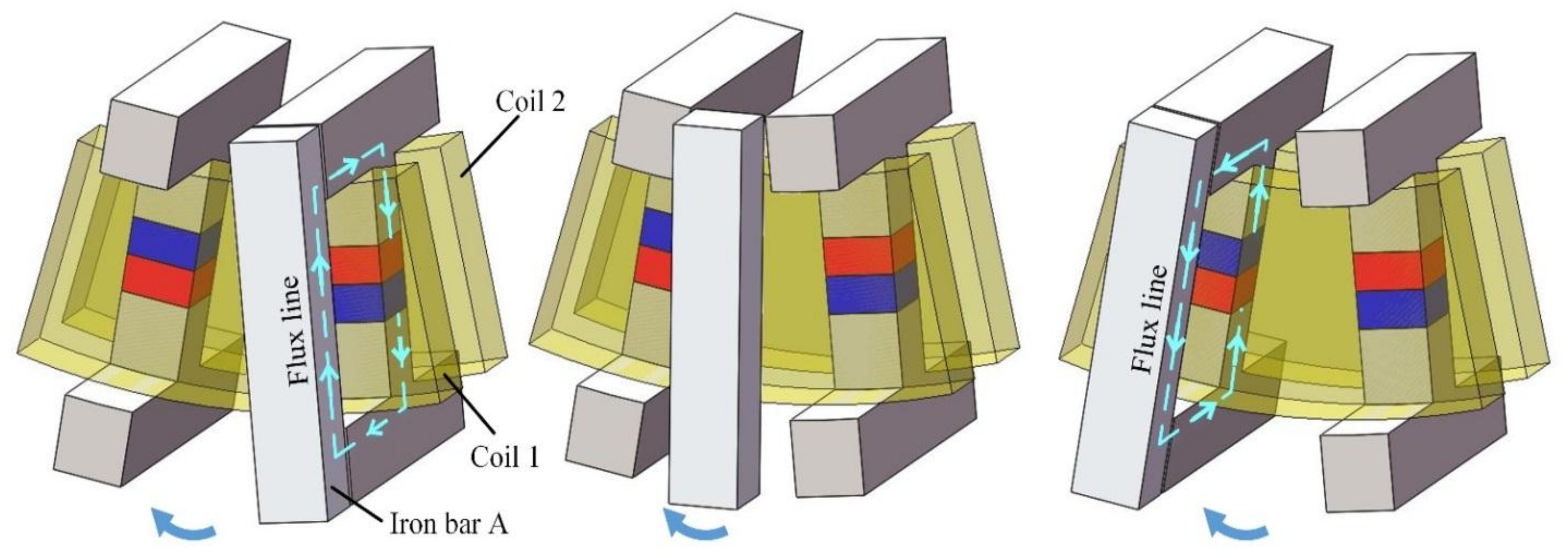
The operating principle of the proposed TFPMDG is illustrated in
Figure 2. Two adjacent H-shaped stator cores are used to reveal the operating principle. Since the iron bars between the two rotor disks are in staggered arrangement along the circumference direction, and the number of irons in a rotor disk is half number of the H-shaped stator cores, while iron bar A is facing the upper part of an H-shaped stator core, the bottom of the H-shaped stator core is facing the air. Consequently, all the flux lines go through coil 1 from the upper part of the H-shaped stator core and iron bar A, and the PM flux linkage of coil 1 reaches its maximum value (positive maximum). On the contrary, neglecting the flux leakage, there are no flux lines going through coil 2 due to the maximum magnetic resistance. With the rotation of iron bar A, the flux linkage will reduce and its value will be zero when iron bar A is in the middle two H-shaped stator cores. After that, the flux linkage will continue to reduce and reaches its negative maximum value, for the reversed direction of the flux linkage. Thus, the value of flux linkage will change from positive maximum to negative maximum with the rotation of the iron bar from an H-shaped stator core to an adjacent one. Because the adjacent H-shaped stator core has a PM with opposite magnetized direction, it can be found that if an H-shaped stator core forms a magnetic circuit on the upper part, the adjacent H-shaped stator core will form a same direction magnetic circuit on the lower part at the same moment. Thus the two coils will have the same voltage variation, and they can be connected in series to constitute a single phase winding. Compared with the TFPMGM in [
29], all the PMs of the proposed TFPMGM can contribute to the energy conversion at any time, which improves the utilization of PMs.
3. Magnetic Circuit Analysis
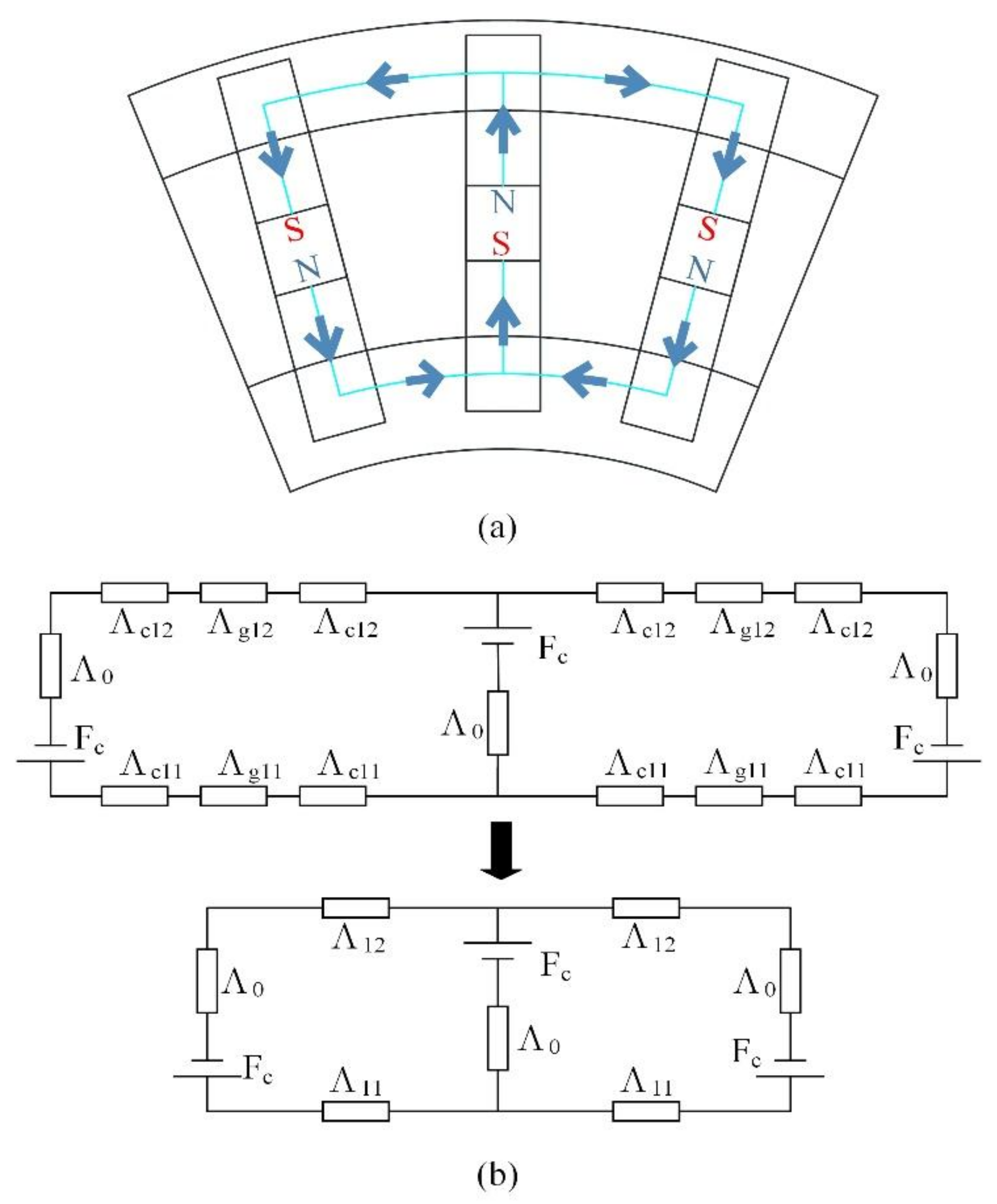
The equivalent magnetic circuit (EMC) is used to calculate the EMF when the proposed TFPMDG is at no load. Since the proposed TFPMDG has a 3D magnetic field distribution, the magnetic flux paths are a bit complicated and flux-leakage at the fringe of each H-shaped core exists, as well as the flux-leakage caused by adjacent H-shaped cores. In order to analyze the magnetic circuit simply, the flux-leakage at the fringe, the curvature, and saturation effect are ignored. And we only take the main magnetic circuit and the flux-leakage caused by adjacent H-shaped cores into consideration.
Figure 3a gives the flux-leakage caused by adjacent H-shaped cores. In the transverse cross section, a PM will form a magnetic circuit with adjacent PMs. However, the magnetic flux doesn’t contribute to the EMF and it will reduce the effective magnetic flux of the main magnetic circuit.
Figure 3b describes the corresponding EMC. The magnetomotive force (MMF)
Fc provided by PM can be calculated by Equation (1):
where
Hc is the coercivity of the PM;
hpm is the thickness of the PM.
In
Figure 3b,
,
, and
are magnetic permeances of the PM, iron core, and air gap, respectively. According to the definition of permeance and magnetic circuit rules, the equations can be obtained as follows:
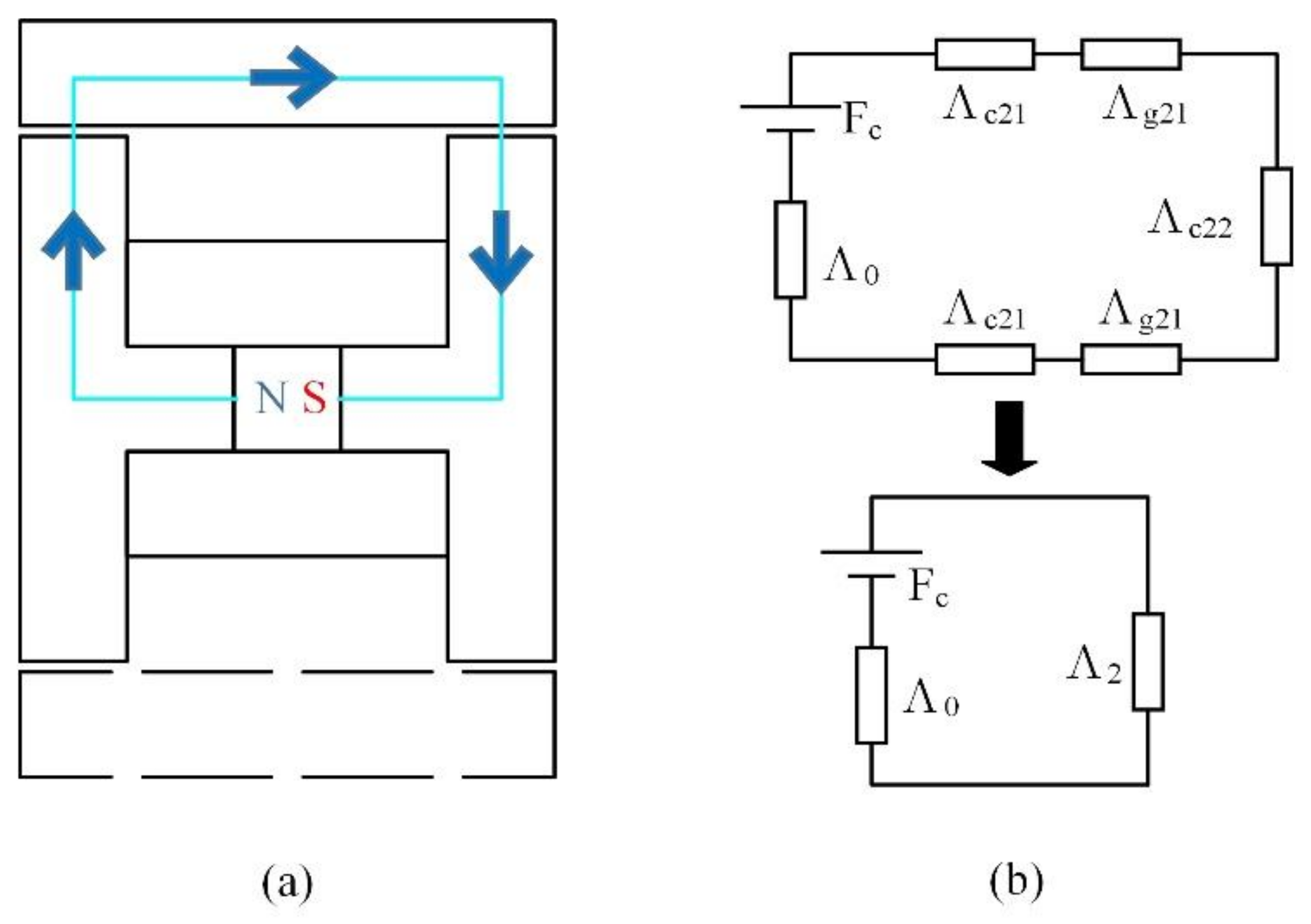
Figure 4a depicts the main magnetic circuit which is in an axial cross section. The corresponding EMC is illustrated in
Figure 4b. Similarly, the equation about the magnetic permeance can be gotten in the following:
Combining these two EMCs of the two cross sections, finally the EMC of the proposed TFPMDG is attained in
Figure 5. In order to calculate the main magnetic flux in
branch, the superposition principle is utilized.
Firstly, only considering the effect of the PM in the middle, the EMC can be obtained in
Figure 6. Therefore, the following equations can be obtained:
where
is the sum permeance of magnetic circuit; Φ is the total magnetic flux of magnetic circuit;
Fm is the MMF in
branch; Φ
12 is the magnetic flux in
branch.
Secondly, the effects of the left and right PMs in
Figure 5 are taken into account, respectively. Owing to the symmetry between the left and right PMs in the EMC, we only need to analyze the effect of one of the PMs. Taking the left PM as an example, the EMC can be obtained in
Figure 7. Hence, the following equations can be obtained:
where Φ
11 is the magnetic flux in
branch.
Finally, because the direction of Φ
11 and Φ
12 is opposite, the total magnetic flux Φ
1, and air-gap magnetic flux density
Bmg can be calculate by the following equations:
where
Am is the area the total magnetic flux goes through.
For the proposed TFPMDG, the fundamental component of the magnetic flux per pole pair per phase excited by the PMs can be calculated by Equation (17)
where
,
S, and
Bmg1 indicate the fundamental component of the magnetic flux per pole pair per phase excited by the PMs, the effective area of one pole, and the fundamental harmonic of the normal component of peak magnetic flux density in the air-gap, respectively.
Thus, when the two rotor disks rotate at the speed of
n r/min, the fundamental magnetic flux can be expressed as
where
kf is a waveform factor, which is depends on the width of stator pole shoe [
30], and
f is the variation frequency of the magnetic flux. They can be obtained by the equations below:
Thus, the EMF of the TFPMDG at no load can be obtained as
where
N is the total turns of the two circular coils. Apparently, the effective value of the EMF is as follows
4. Simulation and Analysis
The three-dimensional (3D) finite element method (FEM) is employed to analyze the electromagnetic performance of the proposed TFPMDG in Jmag-Designer Version 14.0, which is a comprehensive simulation software developed by a Japanese developer named “JSOL Corporation”. The initial TFPMDG has 24 H-shaped stator cores and 12 iron bars with I-shape in each rotor disk. Considering the periodicity of the structure, two adjacent H-shaped cores and two iron bars in
Figure 8a are selected as a basic structural unit for the 3D FEM analysis.
Figure 8b gives the description of the key dimension parameters.
Table 1 lists the key dimensions and major parameters of the initial TFPMDG. It should be noted that in the initial generator, the width of rotor cores is equal to the width of H-shaped stator cores.
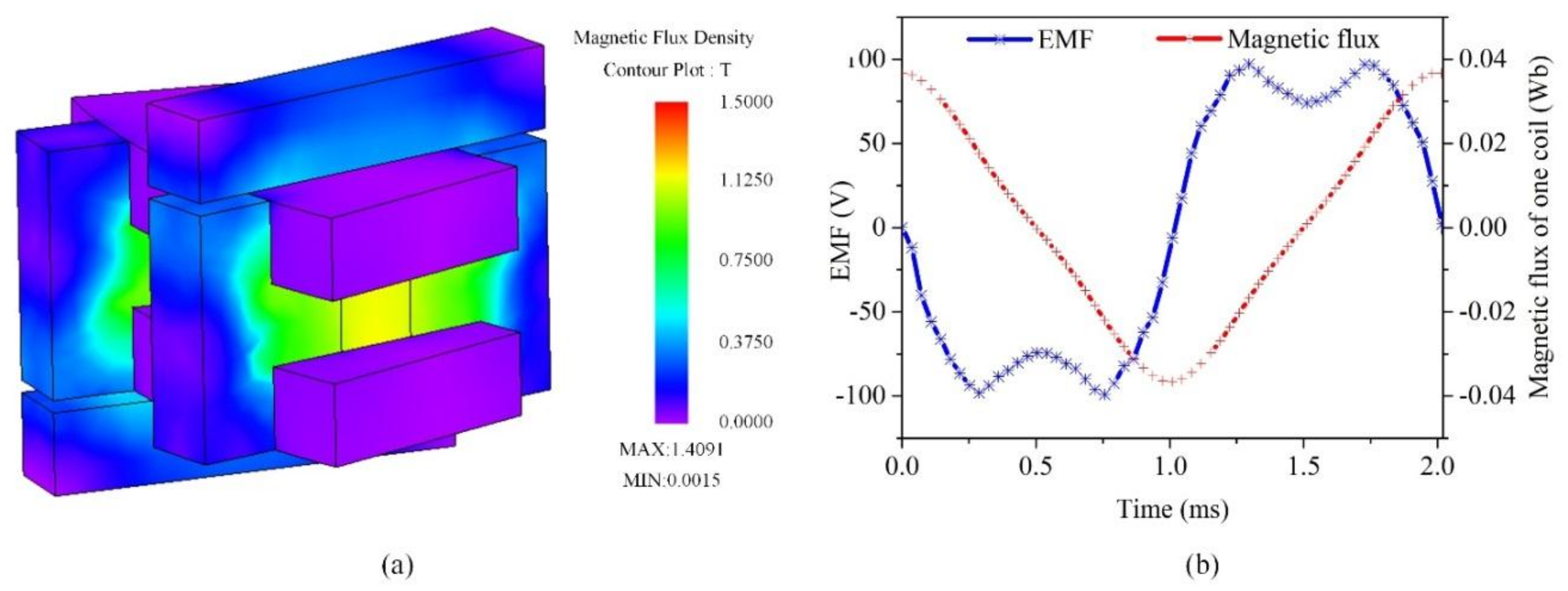
Figure 9a displays the field distributions of the initial TFPMDG at no load. It can be observed that the maximum flux density appears in the stator core, which is approximately 0.36 T, and the average flux density in the stator cores and iron bars is about 0.275 T.
Figure 9b exhibits EMFs of the two coils at no load when the speed of the generator is set to 2500 r/min. It can be seen that the EMF curves overlap basically and the EMF in each coil changes alternately in one cycle, which verifies the analysis of the operating principle in
Section 2.
However, as seen from
Figure 9b, the EMF waveforms are irregular. Specifically, each EMF curve has a bulge in the first half cycle, while there is a dent in the second half cycle. As shown in
Figure 8a, there is a sector air region between two adjacent H-shaped cores. Since the inner and outer ends of an iron bar have the same width in the initial TFPMDG, when the iron bar sweeps over the sector region, the variation of the magnetic fluxes at the inner and outer ends is significantly different. As a result, the total magnetic flux in a coil shown in
Figure 9b does not vary according to the usual law, such as sinusoidal variation. And this is the reason why the EMF waveforms are irregular. In addition, it can be seen that the iron bar is the key factor affecting the EMF waveforms.
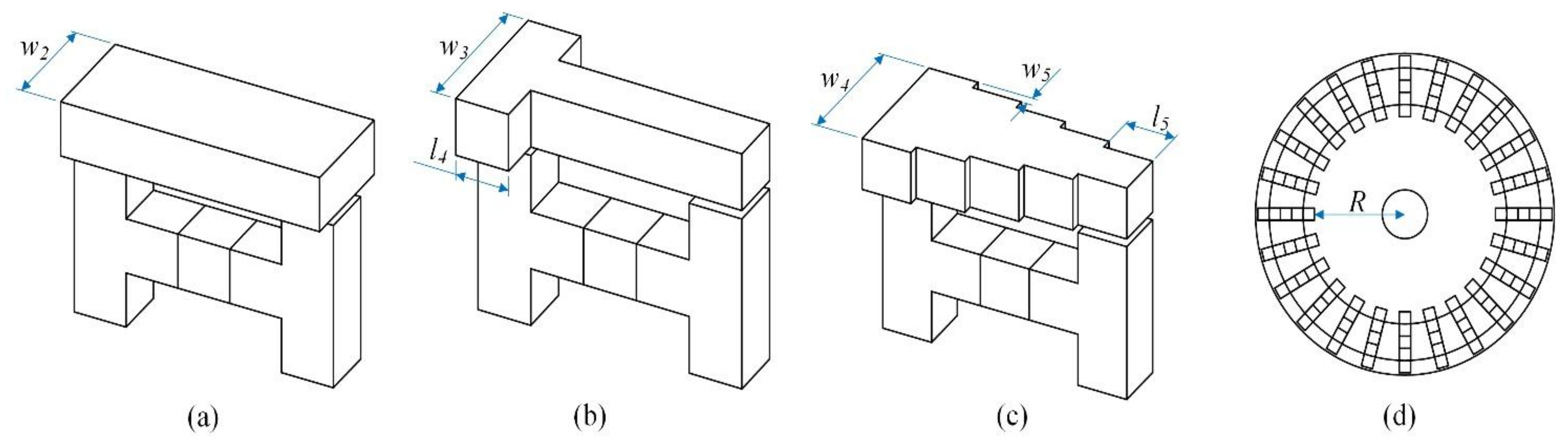
Based on the previous analysis and keeping the dimension parameters of the H-shaped stator cores in the initial TFPMDG unchanged, three TFPMDGs with wider I-shaped iron bars, T-shaped iron bars, and five-stair-step (FST) shaped iron bars are proposed in order to improve the EMF waveforms of the initial TFPMDG, as shown in
Figure 10.
Table 2 lists the major parameters of the iron bars with I-shape, T-shape, and FST-shape.
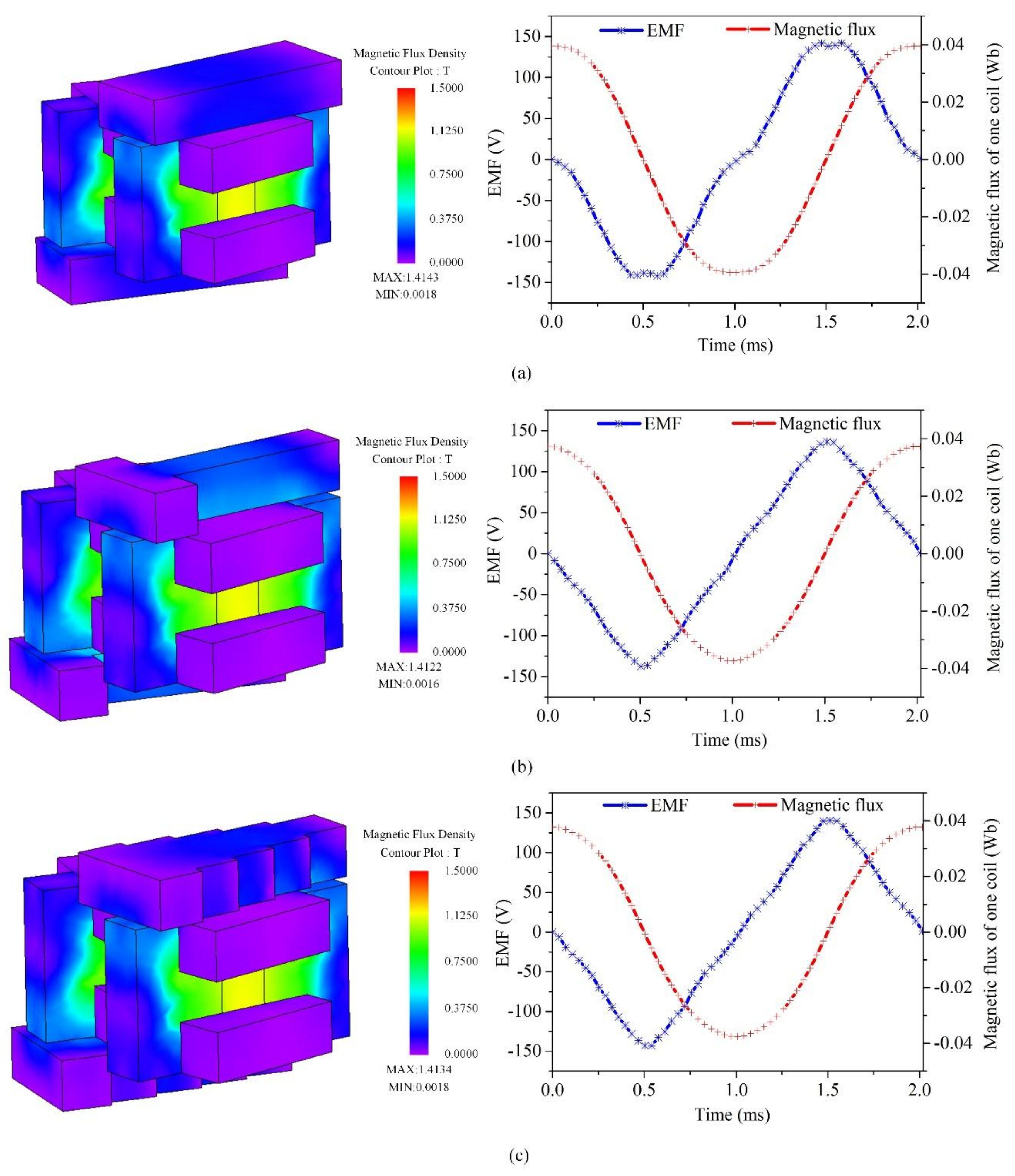
By using the 3D FEM calculation [
31], when the speeds of the three TFPMDGs are set to 2500 r/min, the EMFs at no load can be obtained. The results are exhibit in
Figure 11. Comparing
Figure 11 and
Figure 9b, it is easy to see that the EMF amplitudes of the three TFPMDGs increase greatly. The EMF amplitudes are approximately 50% larger than that of the initial TFPMDG. Moreover, the bulge and dent have been weakened. It means that the EMF waveform of the initial TFPMDG can be obviously improved by changing the shape of the iron bars. In terms of
Figure 11a, the EMF waveform in the TFPMDG with wider I-shaped iron bars has been improved but there is still a small bulge and a small dent in the EMF waveform. The EMF will change slightly nearing
x axis. That is because the rotor iron bar is wider than the stator core and the intersect area of the rotor core and stator cores has little change at the beginning of the rotation. Moreover, the inner end of the rotor iron bar is too wide, and so leakage flux will form. As for
Figure 11b,c, the TFPMDGs with T-shaped iron bars and FST-shaped iron bars can completely eliminate the bulge and dent. This is because the wider outer end of the rotor core can lead to both ends of a rotor core connecting to a stator core at almost the same time during the rotation.
From the perspective of improving the EMF waveforms, both the TFPMDGs with wider T-shaped iron bars and FST-shaped iron bars are good candidates, but the EMF amplitude of the TFPMDG with FST-shaped iron bars is larger than that of the TFPMDG with T-shaped iron bars.
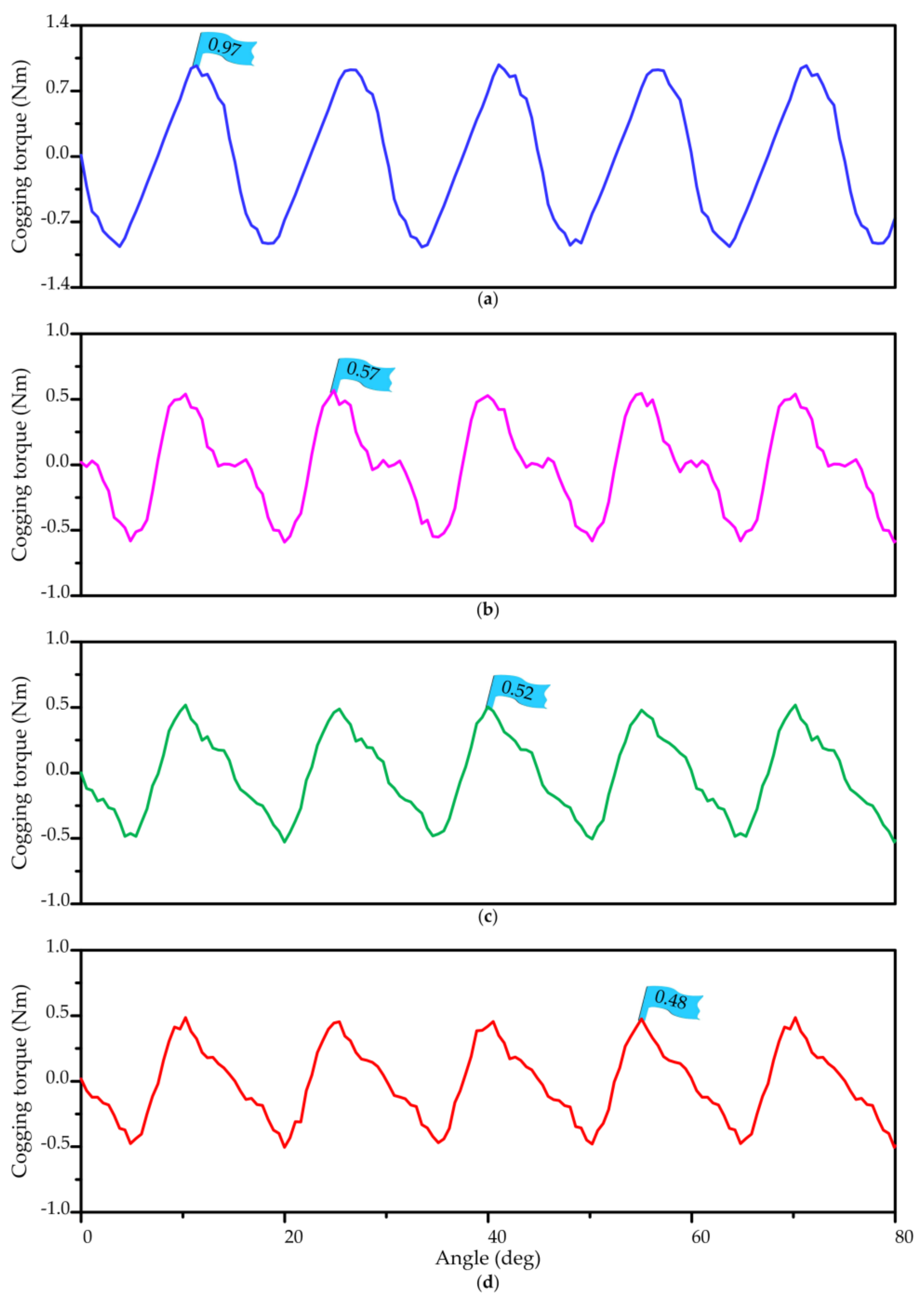
Furthermore,
Figure 12 compares the cogging torque of the four TFPMDGs. It can be observed that the peak value of the TFPMDG with FST-shaped iron bars is the smallest of the four TFPMDGs. Thus, the TFPMDG with FST-shaped iron bars is selected for load analysis by means of 3D FEM and manufacturing the prototype for testing in
Section 5.
Table 3 lists the key specifications of the TFPMDG with FST-shaped iron bars for load analysis. It should be noted that the machine is a single phase generator and the two coils are connected in series in the process of load analysis. For simplicity, the resistive load is selected for analysis.
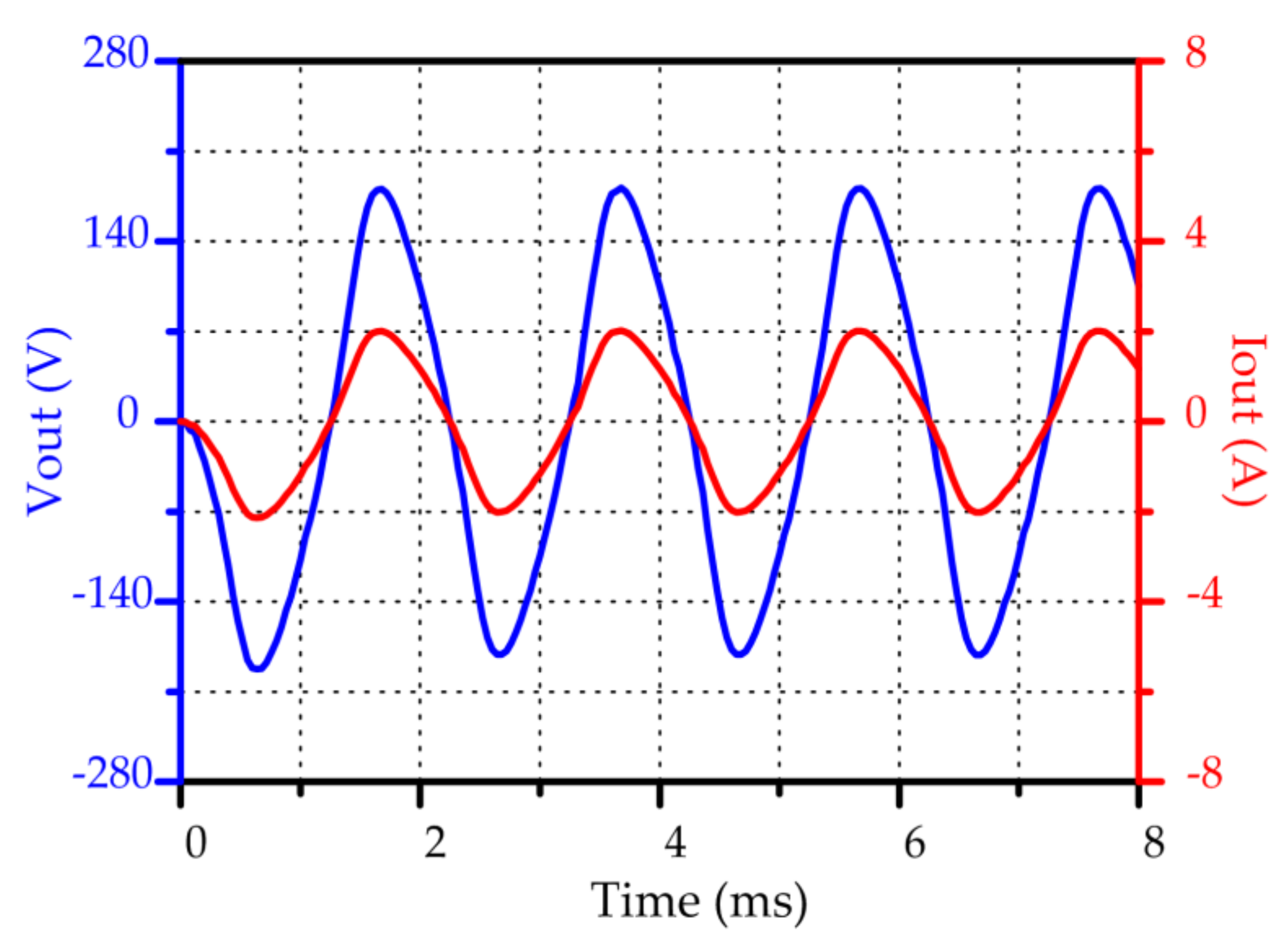
Figure 13 shows the waveforms of load resistance voltage and load resistance current when the generator is connected to a 90 Ω resistance and its speed is set to 2500 r/min. It can be seen from
Figure 13 that the amplitudes of the load voltage and current are 181.59 V and 2.02 A. The output power, Pout, is about 183.41 W, which is obtained by calculating the product of the voltage and current.
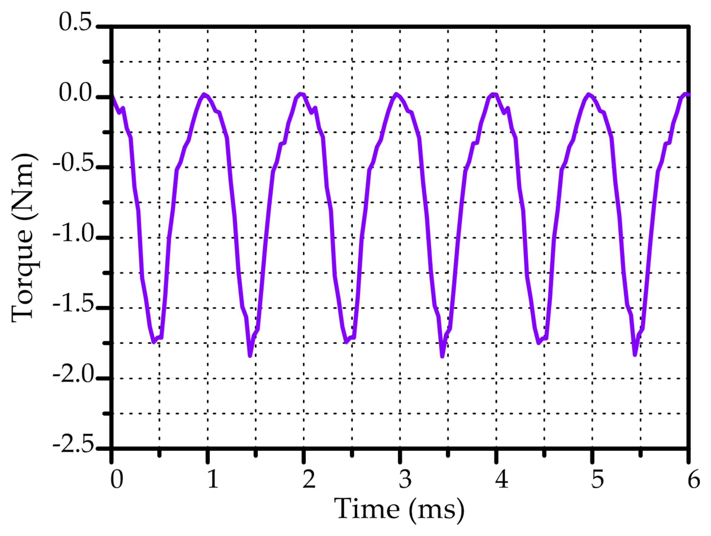
Figure 14 gives the corresponding load torque. Since the machine is a single phase generator, the waveform of load torque is fluctuating. It fluctuates twice in an electric cycle (
T = 2 ms).
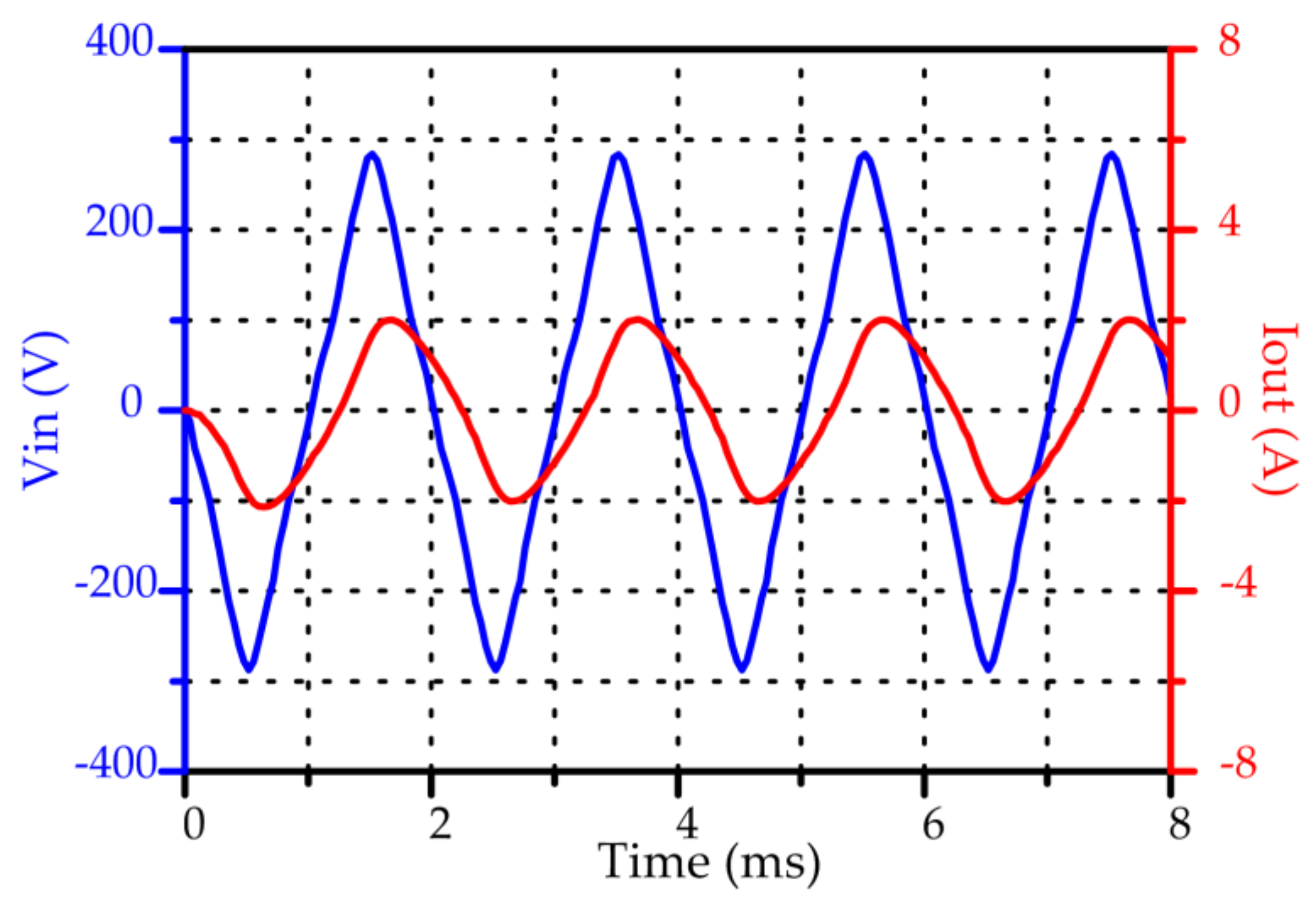
Figure 15 shows the input voltage waveform and output current waveform with 90 Ω resistance. It should be noted that the input voltage is actually the EMF at no load. It can be observed that both the input voltage and output current are not standard sine waves. In order to get the power factor (PF), Fast Fourier Transformation (FFT) is used to calculate the phase angle difference (PF angle) between the two waveforms [
32]. Hence, the PF angle is 36.32 degrees, which means that the PF is about 0.81.
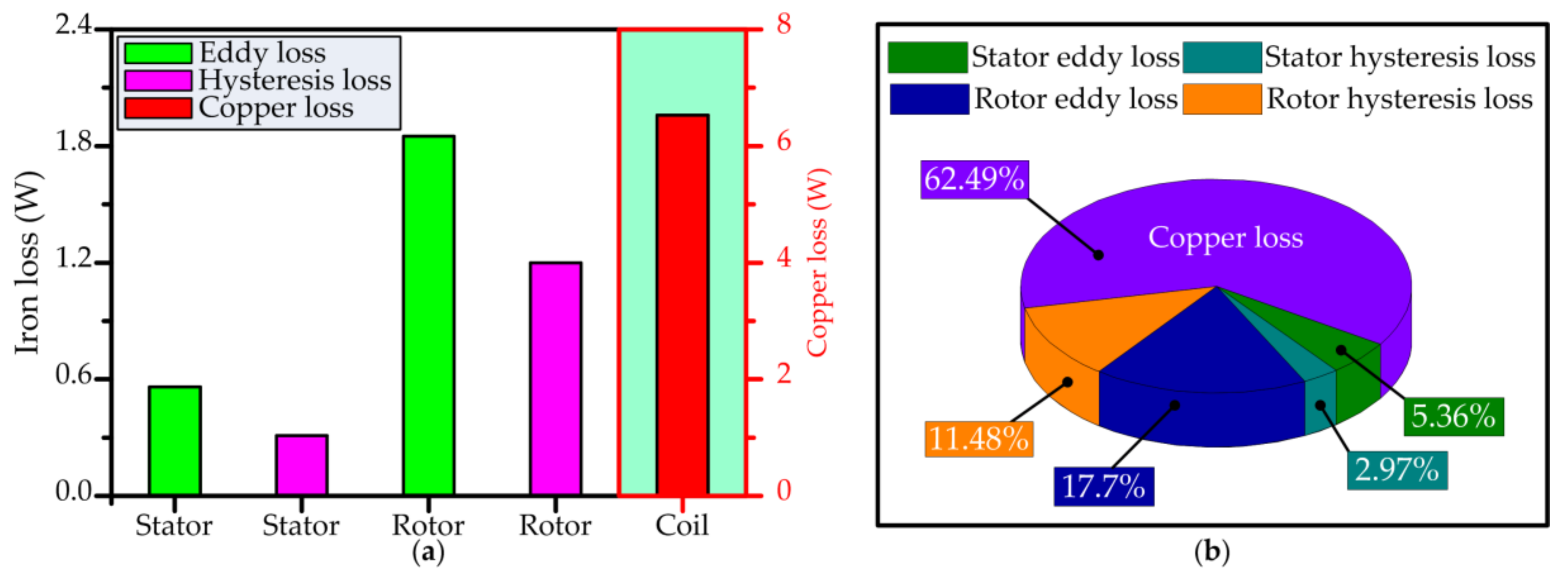
Figure 16 illustrates the loss of each part, and the proportion of the loss of each part to the total loss when the load resistance is 90 Ω and the speed is set to 2500 r/min. It is evident that the copper loss accounts for a considerable proportion in the total loss (62.49%); and, the dominant iron loss is concentrated on the rotor. Without considering the friction, windage, PM loss, and stray loss, the efficiency can be evaluated by the formula below,
where P
copper and P
iron are copper loss and total iron loss, respectively. Therefore, the efficiency of the investigated generator is about 95%.
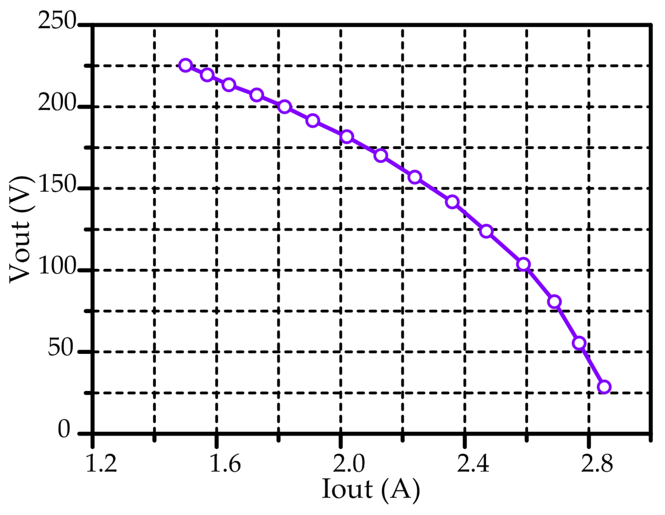
Figure 17 shows the variation of output voltage versus load current. It needs to be explained that the load current, Iout, is the amplitude rather than the effective value. Apparently, the output voltage decreases with the increase in load current.
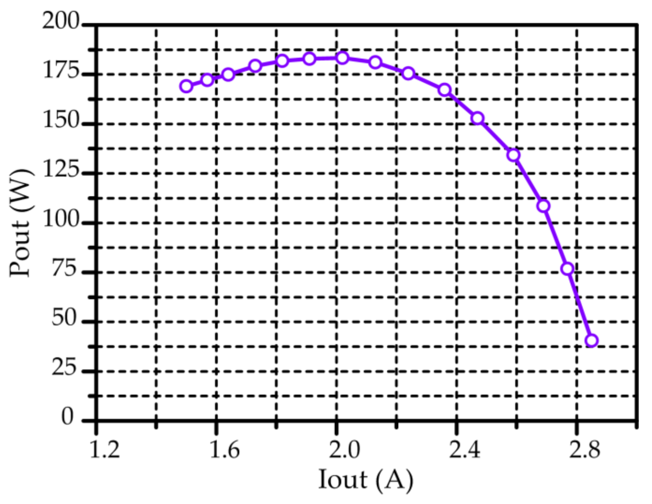
Figure 18 displays the variation of output power versus load current. It is evident that as the load current increases, the power increases first and then decreases. When Iout is approximately equal to 2 A, the output power reaches the maximum, that is, about 180 W.
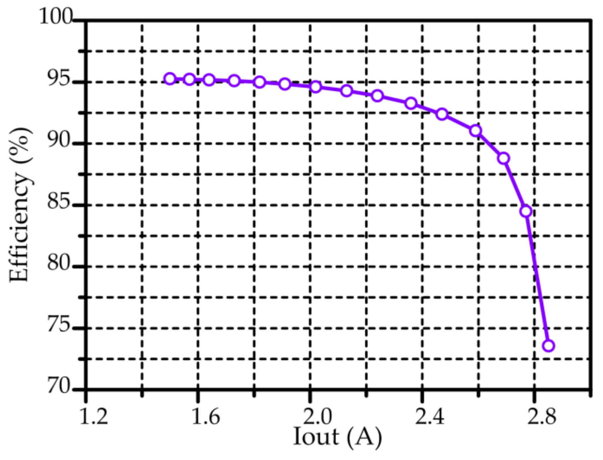
Figure 19 shows the variation of efficiency versus load current. As can be seen from
Figure 19, when the current is less than 2.6 A, the efficiency of the generator is kept above 90%. When the current is greater than 2.6 A, the efficiency decreases sharply with the increase in the current.
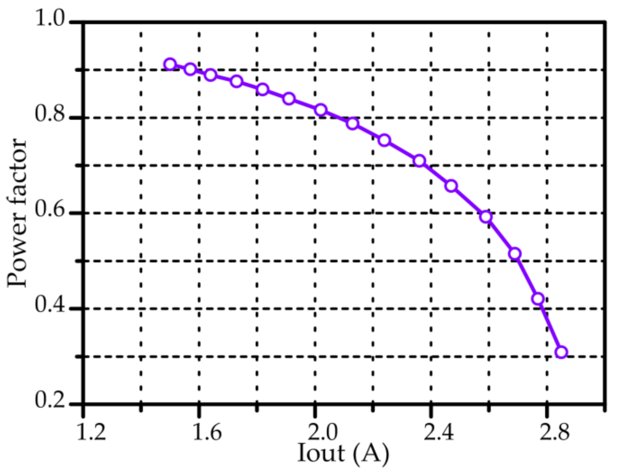
Figure 20 shows the variation of power factor versus load current. Obviously, the PF decreases with the increase in load current. Based on the previous simulation analysis,
Table 4 summarizes the nominal characteristics of the TFPMDG with FST-shaped iron bars.
5. Prototype and Testing
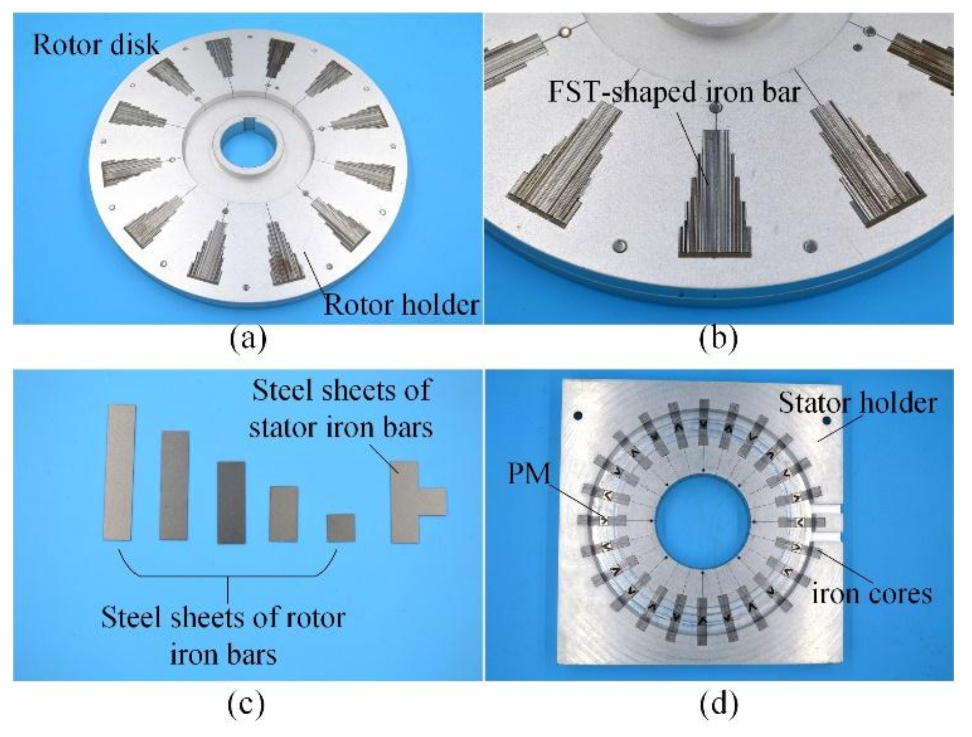
The TFPMDG with FST-shaped iron bars is manufactured to verify the simulation results. The assembly steps of the prototype are as follows:
- (a)
Construction of the aluminum rotor holders, embedding the iron bars with FST shape in the two rotor holders (the FST-shaped iron bars are assembled by five kinds of steel sheets of different length), and gluing the iron bars and rotor holders (
Figure 21a–c);
- (b)
Construction of two circular coils;
- (c)
Construction of the aluminum stator holder, inserting the T-shaped iron cores into the cavities of the stator holder, embedding the PMs in between the T-shaped iron cores, and gluing the iron cores, PMs, and the stator holders (
Figure 21d);
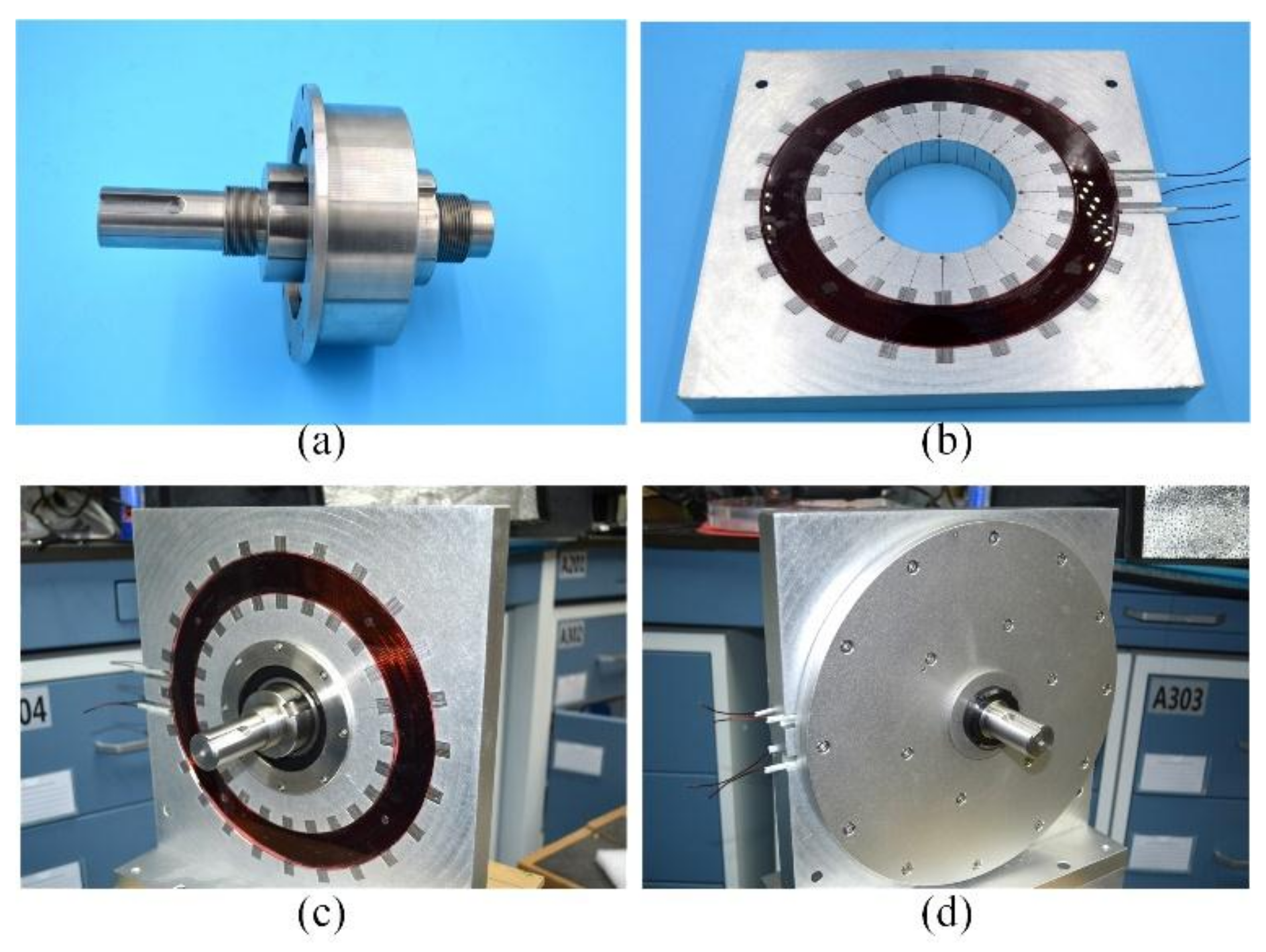
- (d)
Placing insulating paper in the cavities of stator disk in the last step, and gluing the coils in the cavities with acrylic ring sheets (
Figure 22b);
- (e)
- (f)
Assembly of the generator.
The constructed TFPMDG with FST-shaped iron bars is shown in
Figure 22d. The no-load and on-load tests of the prototype are carried out.
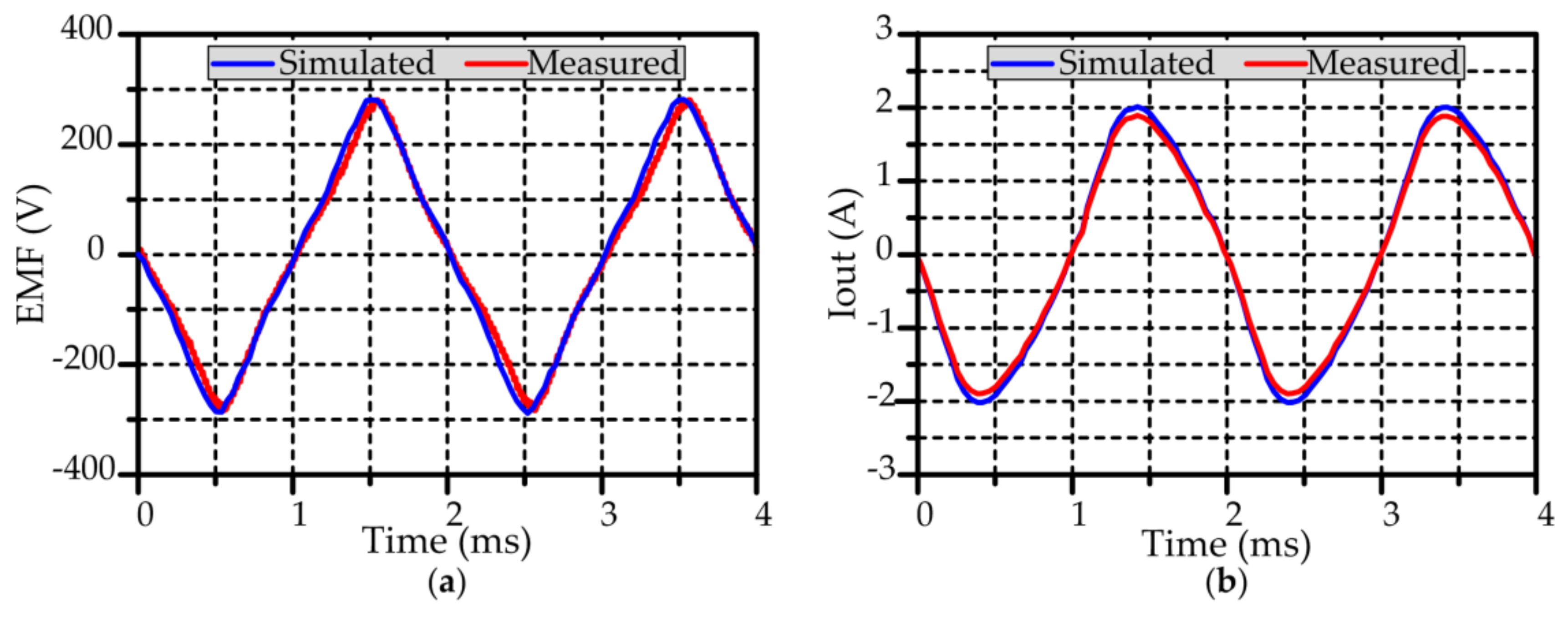
Figure 23a shows the no-load EMF waveforms obtained by measuring and simulation when the generator is at 2500 r/min. It can be observed from
Figure 23a that the no-load EMF waveforms almost overlap, and their amplitudes are about 281 V. The reason for the minimization of the difference is that the machining accuracy and assembly error reduce the length of the air-gaps.
Figure 23b compares the simulated and measured load currents when the generator is connected to a 90 Ω resistance and rotates at 2500 r/min. It can be seen from
Figure 23b that the measured current amplitude is about 1.89 A, while the simulated current amplitude is about 2.02 A. The reason for the difference between the measured and simulated currents is that the leakage inductance is not considered in the simulation. In addition,
Table 5 summaries the other results. It can be found that the measured results are smaller than the simulated results with the no-load EMF. The main reasons are as follows: (1) because the load current is reduced, the measured output power will certainly be reduced; (2) due to the neglect of other losses such as the friction, windage, PM loss, and stray loss, the simulated efficiency is higher than the measured one; (3) since the leakage inductance is not taken into consideration in the simulation, the simulated power factor is higher than the measured one. Therefore, although there are differences between the results, we think it is reasonable and acceptable.


