Abstract
This paper addresses the unbalanced voltage, subharmonic/dc-offset voltage, and low-frequency (LF)/high-frequency (HF) harmonics of a grid voltage tracking method based on second-order generalized integrators (SOGIs) in high voltage/frequency swing on a shipboard photovoltaic (PV)-diesel-battery hybrid power system. To perform this work, a kind of shipboard PV–diesel-battery hybrid power system structure was first analyzed, emphasizing both the active and reactive power (PQ) control strategy and the sensitivity of the phase-locked loop (PLL) that is crucial to the vessel’s electrical networks. Then, the effect of grid voltage harmonics in SOGIs and of voltage/frequency swing on SOGI frequency-locked loop (SOGI-FLL) was studied. Meanwhile, aiming to the adverse power qualities of a shipboard power system (SPS), a SOGI-based structure with prefilter, a dc-offset block, and a positive sequence extractor (SOGI-FDE) was proposed. Finally, to overcome all of the vessel’s grid problems, a new SOGI-based voltage tracking structure, SOGI-FDE-FLL, consisting of SOGI-FDE and SOGI-FLL, was proposed to achieve accurate grid voltage tracking rapidly. This proposed schematic was used as an adaptive grid voltage tracking method to a three-phase three-wire shipboard PV–diesel-battery hybrid power system. Experimental results were obtained validating this proposal.
1. Introduction
Nowadays, diesel-engine synchronous generation is a primary shipboard power system (SPS). However, with the tendency of reducing the use of traditional fossil fuels and limiting the ship large-tonnage, which is increasing quickly with the size of ships and their associated electrical power equipment, the development of new energy supplies instead of diesel is an urgent demand with regard to the quick development of shipboard electric power systems [1,2]. Photovoltaic (PV) generation utilizing solar energy is one of the best choices for power supply on ships due to its excellent economy and high efficiency. However, the features of PV such as intermittency and limited development area, has limited solar-powered ships working within a short navigation range with rather high costs [3]. Hence, the PV–diesel-battery hybrid power system is a promising power supply system in comparison with traditional power generation systems and can enhance fuel economy and the continuity of power supply, reduce marine pollution, and improve grid power quality, system stability, and flexibility [4,5,6].
Onboard AC electrical power system may be categorized as an islanded AC microgrid [7], which causes numerous power quality issues. One prominent problem is the voltage/frequency swing during the start-up and braking of sailing caused by the substantial rapid load of high-power propulsion changing, which will increase power losses and reduce SPS stability, reliability, and security [8,9]. Chinese SPS standards stipulate that the vessel’s grid voltage and frequency variation range must be −10~+6% and −5~+5% respectively [10]. Meanwhile, presently there is extensive use of emerging diode rectifiers, pulsed power-electronics loads, non-linear loads, and asymmetrical loads in the SPSs, which arouse a series of power quality issues of harmonics, unbalanced voltage, as well as dc-offset voltage from scaling errors in the grid voltage measurement of grid current performance [11,12]. When the PV generation technique is applied on a ship for the shipboard PV–diesel-battery hybrid AC power system, a PV inverter is essential to convert PV battery direct currents into alternating currents that are synchronous to the grid. However, as the power capacity of a PV inverter is much lower than that of a diesel-engine synchronous generator for laying area limitations, the PV inverter has less grid-voltage regulation capability and is suitable for the current injection method by means of a diesel-engine synchronous generator working in standalone mode as a slack bus. Hence, how the vessel’s fundamental frequency sequence voltage can be quickly and accurately tracked under such adverse grid conditions has become a critical concern with respect to shipboard PV–diesel-battery hybrid power systems.
Usually, a phase-locked loop (PLL) in a synchronous reference frame (SRF-PLL) is used to detect the phase angle, amplitude, and frequency of the grid voltage in three-phase systems for Park transformation as a phase detector (PD). However, its performance deteriorates when the grid is non-sinusoidal for harmonics, unbalanced, or with dc bias. Its d-axis and q-axis voltage components in the SRF are no longer constant but contain disturbances oscillating at integer multiples of fundamental frequency [13]. Hence, the phase error is inaccurate, which leads to a detection error. To eliminate harmonic disturbance, various kinds of in-loop and out-loop filter techniques have been proposed. In [13], a moving average filter (MAF) PLL was proposed by passing the dc component and completely blocking the frequency components of integer multiples of 1/Tw (Tw is MAF window length) in Hertz, but considerably slowed down its dynamic response. Differential MAF-PLL was proposed by increasing the open-loop bandwidth and significantly improving the dynamic performance of MAF-PLL [14]. In [15], a notch filter PLL with a band-rejection filter was introduced. It significantly attenuated signals within a narrow band of frequencies, passed all other frequency components with negligible attenuation, and minimized the phase delay in the PLL control loop. Moreover, a delayed signal cancellation PLL [16] and a PLL based on a second-order generalized integrator (SOGI), known as SOGI-PLL [17], were reported. For eliminating unbalance influence, an enhanced PLL [18,19] and a PLL based on a generalized integrator (GI) and SOGI-PLL [17,20] have been reported. The enhanced PLL (EPLL) consists of a frequency-adaptive filter whose frequency follows the fundamental frequency of the grid. The quartz-crystal-based PLL (QPLL) was designed by using the estimation of the in-phase and quadrature-phase amplitudes and the frequency of the fundamental input signal. Finally, the SOGI-PLL has a GI as the main block that generates in-phase and quadrature-phase sinusoidal components of the input signal. As voltage/frequency swing, a structure simplification of the SOGI-PLL that replaces the PLL with a frequency-locked loop based on a SOGI (SOGI-FLL) was introduced in [21]. The FLL estimates the frequency of the input signal and is used to tune the SOGI, with the grid voltage frequency. In [22], a multiple SOGI was introduced that used a cross-feedback network consisting of multiple SOGIs to reject the harmonics from the grid. The multi-SOGI-FLL was designed to achieve a fast response, but its response can be distorted by subharmonics in the input signal. In a word, all PLL techniques mentioned here were designed for one or two specific power quality issues but cannot be used directly on a vessel with severe grid conditions.
Due to two poles of SOGI transfer function, SOGI can be used as a proportional-resonant (PR) controller in an αβ-frame to fully follow input sinusoidal waves with zero steady-state error [23,24]. It is equivalent to SRF-PLL in the dq-frame as a proportional-integral (PI) controller according to frame transformation [25]. Meanwhile, its in-phase and quadrature-phase outputs have the characteristics of frequency selection and a low-pass filter (LPF), respectively. Hence, it can be used as the PLL, the voltage/current PR controller, the filter, and so on for its harmonics attenuation, simple configuration, and flexibility. In this paper, SOGIs in different functions were used for a specific shipboard PV–diesel-battery hybrid power system for grid voltage tracking. In this hybrid SPS, the diesel-engine synchronous generator worked in standalone mode as a slack bus, where the diesel governor and synchronous excitation system maintained the grid voltage frequency and amplitude of the shipboard PV–diesel-battery hybrid power system. The PV–battery inverter acts as an active and reactive power (PQ) bus to inject the desired active and reactive powers given by the power management system (PMS) to the grid. Hence, grid voltage tracking is necessary for the PV inverter voltage reference generator. A SOGI-based frequency-locked loop (SOGI-FLL) is one way to capture the voltage and frequency at voltage/frequency swing and filter harmonics but is invalid for addressing a vessel’s issues of low-frequency(LF) harmonics, including subharmonics, unbalanced voltage, and dc-offset voltage. For the subharmonic/dc-offset non-attenuation limitation of SOGI quadrature-phase output, a SOGI-based structure with prefilter, a dc-offset block, and a positive sequence extractor (SOGI-FDE)was proposed consisting of three SOGIs using in-phase output with subharmonic/dc-offset attenuation. Therefore, an adaptive grid voltage tracking schematic, SOGI-FDE-FLL, with a quick and accurate SPS integrating a SOGI-FDE and a SOGI-FLL was devised. This new voltage tracking schematic was composed of four SOGIs. The former unit was for pre-filtering LF harmonics, for blocking subharmonics/dc bias, and for obtaining an ideal positive α-axis sequence component, whereas the latter unit was for the adaptive tracking of a vessel’s grid voltage amplitude and frequency in voltage/frequency swing.
This paper is organized as follows. Section 2 describes the shipboard PV–diesel-battery hybrid power system configuration and the PV–battery inverter control strategy. Section 3 analyzes in detail the SOGI and the SOGI-FLL and reveals SOGI’s limitations and problems under a given vessel’s adverse grid conditions. Section 4 proposes the SOGI-FDE structure, and on this basis an adaptive voltage tracking structure, SOGI-FDE-FLL, which was our method of tracking a vessel’s grid voltage and the key parameters of an optimized design. Section 5 presents the experimental results to confirm the theoretical analysis presented. Section 6 presents the conclusion of this work.
2. Power System Description
The adaptive grid voltage tracking method described here for applying a photovoltaic battery to SPS revealed superior performance in adverse grid conditions. A shipboard PV–diesel-battery hybrid power system was chosen to introduce the proposed method in a practical environment.
2.1. Shipboard PV–Diesel-Battery Hybrid Power System Configuration
Figure 1 depicts the configuration of a shipboard PV–diesel-battery hybrid power system, which was composed of three kinds of power supply (a PV unit, a diesel-engine synchronous generator, and a battery unit), onboard electrical loads, and a PV–battery inverter. The PV unit included a group of PV cells and a dc–dc converter with one-way power flow for maximum power point tracking (MPPT) and dc output voltage stability. The battery unit consisted of a quantity of lead-acid or lithium battery cells, with parallel and series connection, and one bidirectional dc–dc converter as a charging or discharging circuit. The power flow of this battery converter was provided by a power management system (PMS) based on the battery’s state-of-charge (SOC), the surrounding temperature, the load power, etc. The above two dc–dc converters connected the inverter to the AC bus to which the diesel-engine synchronous generator was connected. These three units provide electricity together to the onboard electrical loads, which differ from a terrestrial power-electronics-based distributed power generation system (DPGS). For the limitation of deck area, the electric power capacity of the PV unit, compared to the diesel generator unit, was lower. Meanwhile, considering the vessel’s safety on the ocean as a moving platform, the PV unit equipment must satisfy the rules and requirements of navigation safety.
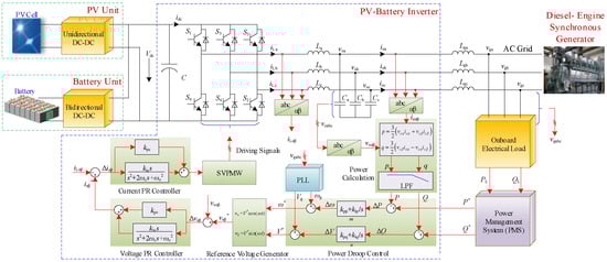
Figure 1.
Schematic of the shipboard PV–diesel-battery hybrid power system.
In this case, the diesel-engine synchronous generator worked in standalone mode as a slack bus where the diesel governor and synchronous excitation system maintained the grid voltage frequency and amplitude of the shipboard PV–diesel-battery hybrid power system. The PV–battery inverter acts as a PQ bus to inject the desired active and reactive powers given by the PMS to the grid.
In this power system structure, the PV–battery inverter is the key role for the interface of PV and battery to the grid, which was composed of a three-phase full bridge circuit and inductor and capacitor (LC) output filter. The extra line inductance Lg connecting the PV–battery inverter and AC grid reduced the active and reactive power flows coupling. The active and reactive power outputs of the inverter are given by
where P and Q are the active and reactive power outputs; is the angle between the diesel-engine generator and the PV–battery inverter; X is the line impedance; Vg and Vo are the output voltages of the diesel-engine generator and PV–battery inverter, respectively. P and Q can be controlled by V and from Equations (1) and (2).
2.2. PV–Battery Inverter Control Strategy
The control part of the PV–battery inverter consisted of inner voltage and current control loops, and outer P and Q droop control loops, assigning power by mimicking the static droop feature of a synchronous generator. The voltage and current control loops were to maintain the frequency and amplitude of the output voltage to the reference, which was regulated by the P and Q droop loops. Furthermore, the P and Q droop loops may adjust the R/X ratio of the output impedance “seen” by the inverter, which was composed of the power calculation, the power droop control, and the reference voltage generator. The inverter active power P and reactive power Q was obtained by calculating the inverter output current and voltage. The difference in active and reactive power (ΔP and ΔQ) was found via comparison with the corresponding reference active power P* and reactive power Q* from the PMS by the given optimization algorithm. Then, the angular frequency and voltage differences (Δω and ΔV) were obtained as the active power and reactive power PI controller outputs with ΔP and ΔQ as the relevant inputs. The inverter output voltage angular frequency reference ω* and amplitude reference V* were derived by tracking the output voltage angular frequency ωg and amplitude Vg by the phase-locked loop (PLL) and minus Δω and ΔV. ω* and V* had droop characteristics, which can be given by
where kpp and kip are the proportional and integral coefficients of active power PI controller; kpq and kiq are the proportional and integral coefficients of the reactive power PI controller, respectively. Both the active and reactive power PI controllers are essentially adaptive droop coefficients.
The inner voltage and current control loops adopted the αβ stationary reference frame and PR controller for tracking the sinusoidal voltage reference with zero static error. The inverter’s output power can follow the power reference given by PMS by space vector pulse width modulation (SVPWM) and the power switches control.
In all, for this shipboard PV–diesel-battery hybrid power system with finite power capacity, the PLL is one of the most important units for the PV–battery inverter as a current source. However, for special and serious grid problems regarding the power quality of broad voltage/frequency swing in heavy load transients, harmonics, unbalanced voltage, and subharmonic/dc-offset voltage in the SPS, the PLL’s accuracy and response directly influences the overall SPS’s dynamic characteristic and stability. In this paper, the SOGI algorithm was chosen as the basic unit for grid voltage tracking. In the next section, the SOGI structure and its limitations are analyzed in detail.
3. SOGI Theories and Its Limitations
3.1. SOGI
Figure 2a depicts the block diagram of a SOGI structure. The SOGI is a frequency-adjustable resonator that is damped by an output loop. This outer loop introduces the error ev between the resonator output vα and the input signal v in the resonator input through gain k.
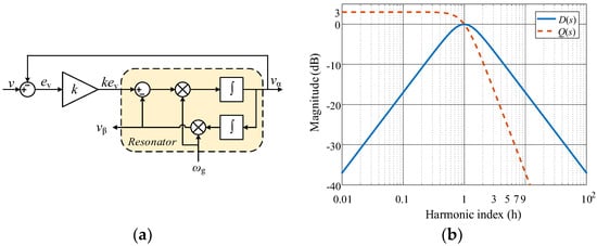
Figure 2.
SOGI structure and its magnitude plots of D(s) and Q(s) for k = 1.414: (a) The SOGI structure and (b) magnitude plots of D(s) and Q(s) for k = 1.414.
The SOGI outputs are vα and vβ, which are, respectively, the in-phase and quadrature-phase with the input signal v. From the input-to-output point of view, the SOGI behaves as a narrow bandpass filter (BPF) for vα to be a specific frequency selector, and as a low-pass filter (LPF) for vβ to be a high-frequency harmonics suppressor. The corresponding transfer functions are
where ωg is oscillation frequency; and k is a damping constant of the SOGI system which is in direct proportion to bandwidth and can be determined by the scope frequency of input voltage. The SOGI is kept as an underdamping system for a better transient response, given k < 2. The bode magnitude plots of Equations (5) and (6) are depicted in Figure 2b for k = 1.414.
According to Equations (5) and (6), given that the error band is 5%, the key parameters related to the SOGI time response and frequency selectivity are the settling time:
and the SOGI BPF gain at a given harmonic h order of ωg
where 0 < k/2 < 1 and h is an odd integer number, and h >> 1. Taking into account the typical h values 3, 5, 7, and so on, Equation (8) can be further simplified as
From Equations (7)–(9), it can be seen that the SOGI has a tradeoff relationship between harmonic attenuation and settling time. The value of settling time should be decreased when the SOGI is used on the occasion of serious voltage/frequency variation.
However, when the frequency of the grid voltage swing as well as the in-phase and quadrature-phase voltage frequencies are unstable for the oscillation frequency ωg coming from outside, an adaptive frequency-locked loop (FLL) unit is necessary.
3.2. SOGI-FLL
Based on the SOGI structure shown in Figure 2, the error transfer function E(s) from input signal v to error e can be deduced:
Figure 3a depicts the bode magnitude and phase plots of Q(s) and E(s). It can be seen that the relationship between the input signal frequency and ωg can be obtained by the sign of vβ multiplied by v. The SOGI-FLL scheme is shown in Figure 3b, where ωo is preset to the grid rated frequency, and γ is the proportional rate of the frequency differential coefficient; voltage normalization can eliminate the impact of voltage amplitude fluctuation on the SOGI’s in-phase and quadrature-phase voltage.
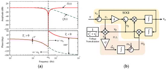
Figure 3.
The Q(s) and E(s) bode magnitude-phase plots and a SOGI-based frequency-locked loop (SOGI-FLL) schematic: (a) Bode plots of Q(s) and E(s); (b) SOGI-FLL schematic.
Setting input voltage , Equation (5) is further deduced:
where , and . Hence, the steady vα and vβ can be deduced as
where Vα and Vβ are the corresponding amplitude of vα and vβ. e is defined as the frequency error, which is
where Δω is the deviation of ω and ωg, namely
The corresponding average value of e in the fundamental frequency can be implied
which is a one-order integrator frequency without a steady-state error. Figure 4 depicts the steady equivalent frequency closed loop system. ωg can be regulated and go back to ω ultimately for the integrator term. The system transfer function can be expressed as
where T is the time constant, and . The rise time tr of the frequency in step response is
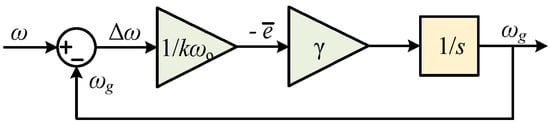
Figure 4.
Equivalent angular frequency control system.
3.3. Limitations of SOGIs
Quickly obtaining the accuracy grid voltage amplitude and frequency in the PV–diesel-battery hybrid power system is key for the serious voltage/frequency swings in the process of ship load mutation. The SOGI has the characteristics of sinusoidal signal tracking for second-order resonant and active filtering for HF attenuation as well as adaptive lock frequency when connecting the FLL unit. However, a SOGI will run into problems when it is applied to an SPS for a PV–battery inverter PLL.
3.3.1. Unbalanced Voltage Impact on SOGI Input Signal
For unequal three-phase heavy loads connected to the grid easily arousing unbalanced grid voltage in an SPS, the unbalanced grid voltage vgabc can be expressed as
where vgabc+, vgabc−, and vgabc0 represent its positive sequence, negative sequence, and zero sequence components, respectively. Accurate grid voltage information cannot be obtained by SOGI on unbalanced voltage due to the unequal three-phase voltage amplitude. Hence, for SPS application, a positive sequence extractor (PSE) unit should be included at the front of the SOGI.
3.3.2. Subharmonic and dc-Offset Impact on SOGI Quadrature-Phase Output Signal
Assuming there are dc-offset components in the input signal v of the SOGI, namely
where F is the ratio of subharmonic amplitude to fundamental voltage amplitude; ωL is the subharmonic angle frequency and, when ωL is lower or zero, namely ωL << ωg, and φL is close to π/2, can be expressed as
From Equations (11)–(14), vα and vβ are approximately simplified to
Figure 5 shows the SOGI response to a subharmonic and a dc-bias in k = 1.414. The subharmonic was 5 Hz at 20% of V, and the dc bias was equal to 20% of V. As seen in this figure, this subharmonic made vβ produce a double sinusoidal envelope with a 5 Hz and a 0.56 amplitude difference; the dc bias brought a 0.28 dc bias to vβ. The presence of subharmonics and dc bias directly translated to the output vβ with the gain of kF and had a direct impact on the SOGI quadrature-phase output, but had almost no impact on in-phase output, which can produce problems and distortion in all SOGI-based structures including SOGI-FLL. This impact can also be illuminated by the quadrature-phase behavior of an LPF with gain k, as seen in Figure 2b.
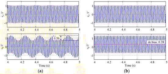
Figure 5.
Time response of the SOGI vα/V and vβ/V for an input signal including a subharmonic and a dc-bias respectively in k = 1.414: (a) time response for the subharmonic of 5 Hz/0.2 V amplitude transmitting; (b) time response for 0.2 V dc bias transmitting.
Moreover, when the SOGI-FLL is applied to SPS (as shown in Figure 1 for PLL), the existing subharmonics and dc bias may arouse the oscillation of voltage in amplitude and frequency, which makes the voltage reference of the voltage and current close loops unstable, which then affects the stability of the whole shipboard PV–diesel-battery power system. This kind of oscillation is more serious with the dc offset rise. Hence, SOGI-FLL cannot be used directly, and a low-frequency attenuation unit is needed.
3.3.3. Low-Order Harmonic Impact on SOGI In-Phase Output Signal
The presence of low-order harmonics in the input signal has a direct impact on the SOGI in-phase output since this output behaves as a bandpass filter (BPF) with −20 decibels per decade slope at frequencies greater than the oscillation frequency (see Figure 2b). This attenuation rate obtains a better filtering performance for switching harmonics but is not sufficient for low-order harmonics. To evaluate this problem, Figure 6 shows the SOGI in-phase response to 5th and 7th harmonics that are both at 15% of the fundamental voltage. The 5th and 7th harmonics were partly translated to the output vα and aroused a higher (5.21%) total harmonics distortion (THD). When SOGI was directly used in the proposed SPS shown in Figure 1, the in-phase output signals with low-frequency harmonics could be directly delivered to the grid through the PV–battery inverter making grid-injected current distortion, which then decreased the power qualities. Hence, a sharp slope of attenuation to harmonics is necessary to deal with the low-order harmonics existing in SPS.
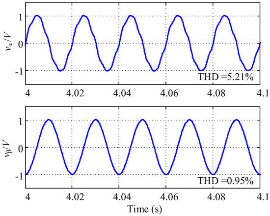
Figure 6.
The SOGI vα/V and vβ/V response with the 5th and 7th harmonics both with 15% voltage amplitude, and the corresponding THD is 5.21% and 0.95%.
4. The Proposed Adaptive Voltage/Frequency Tracking Method Based on SOGIs
A SOGI was considered in this study for its BPF for in-phase output and its LPF for quadrature-phase output. However, when applied to an SPS for voltage tracking, the primary issues were the unbalanced voltage impact on the input signal, the subharmonic and dc-offset impact on the quadrature-phase output signal, and the low-order harmonic impact on the SOGI in-phase output signal.
4.1. The Proposed SOGI-FDE Configuration
The three-phase three-wire system is adopted in most cases for high reliability on the shipboard power supply. Once the three-phase voltage is unbalanced, there are positive and negative sequence voltage terms as shown in Equation (20). Setting vgαβ as a three-phase grid voltage in the αβ-frame, the corresponding positive sequence term can then be expressed as
where Tαβ is the coordinate transformation (CT) from the abc-frame to the αβ-frame, namely,
In this paper, to simplify the schematic of the PLL under adverse grid conditions in the SPS, a synthetic SOGI-based structure with prefilter, a dc-offset block, and a positive sequence extractor (SOGI-FDE) as depicted in Figure 7, is proposed. This structure is composed of a coordinate transformation (CT) Tαβ for the grid voltage abc/αβ-frame transformation and three SOGI units. SOGI I and II, connected to the grid voltage in α- and β-frame components as the in-phase outputs, constitute two active filters (AF) and a subharmonics/dc-bias eliminator for grid voltage in the stationary α-axis and β-axis components, respectively, for LF attenuation. Meanwhile, SOGI III, linked to SOGI II, positively rotates the β-axis component vgβ’ π/2 for the imaginary unit j generator of PSE in Equation (25). The PSE unit extracts the positive sequence α-axis component from the unbalanced three-phase grid voltage.
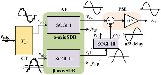
Figure 7.
The proposed SOGI-FDE configuration.
4.2. Proposed SOGI-FDE-FLL for Vessel’s SPS in Adverse Grid Conditions
For the mentioned shipboard PV–diesel-battery hybrid power system in Section 2, the PQ control method was adopted for the PV–battery inverter due to the lower capacity of the photovoltaic battery when compared to a diesel engine on the vessel. The grid-voltage and frequency information are needed to generate a voltage reference for the voltage and current closed-loop control. However, for the vessel’s adverse grid condition of serious voltage/frequency swing, harmonics, unbalanced voltage, subharmonics, and dc bias component, an adaptive grid voltage/frequency tracking method based on SOGIs to a PV–diesel-battery hybrid SPS was proposed, as depicted in Figure 8. This schematic is composed of SOGI-FDE and SOGI-FLL, named SOGI-FDE-FLL.
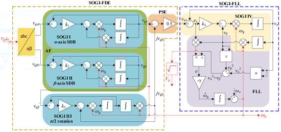
Figure 8.
The proposed SOGI-FDE and SOGI-FLL based SOGI-FDE-FLL schematic.
In this scheme, the FLL is used only in the α-frame to make the sequence detection adaptive to the grid frequency. The SOGI-FDE unit, for a pre-filter, a subharmonic and dc-offset eliminator and a positive sequence extractor, is connected directly to the vessel’s grid to obtain the positive sequence fundamental voltage vα+ without the subharmonics and dc bias component. From the SOGIs’ characteristics of Equations (5) and (6) and the abc-frame to αβ-frame transformation of Equations (25) and (26), the voltage amplitude, frequency, and phase of vα+ is the a-axis positive sequence voltage in the abc-frame. This was the key opinion of this paper to track vα+ to obtain accurate voltage and frequency estimated values instead of tracking grid voltage vgabc with more power quality problems directly.
The SOGI-FLL unit, a grid voltage/frequency estimator, is used to quickly obtain accurate information of grid voltage and frequency in their serious fluctuations. Vg, the estimated voltage amplitude, is calculated as the root square of its in-phase and quadrature-phase output, whereas the estimated frequency ωg is given by an adaptive frequency schematic of an equivalent frequency closed-loop control. Vg and ωg subtract the differences of voltage and frequency obtained from Q-V and P-f droop relationships, respectively, and then reference the voltage generator to form the three-phase reference signal of the voltage/current closed-loop control system as shown in Figure 1.
In the above proposed schematic, the SOGI-FDE unit is in front of the SOGI-FLL. vα+, the input signal of SOGI-FLL, is associated with the vgα and jvgβ transmitted from the grid α-frame component vgα0 by SOGI I and from the β-frame component vgβ0 by SOGIs II and III for PSE. Meanwhile, it is transmitted through SOGI IV to the in-phase output vα. Hence, the schematic can be considered as a double-input single-output system. If the damping constant of all the SOGIs are equal, the Laplace transfer function G1(s), the ratio of vg to vgα0, and G2(s), the ratio of vg to vgβ0, can be expressed as
where D(s) and Q(s) are the SOGI’s transfer functions of corresponding in-phase and quadrature-phase output to input signals (see Equations (5) and (6)).
Figure 9 depicts the D(s), G1(s), and G2(s) magnitude plot in LF harmonics with the same damping constants of k = 1.414 and oscillation frequency of ωg = 314 rad/s. All of these have the capability of dc bias attenuation. D(s) represents the 1st-order SOGI of in-phase output with a narrow BPF, but insufficient LF harmonics suppression at 20 dB per decade slope. G1(s) was obtained by the 2nd-order SOGI, where the LF harmonics obtain substantial attenuation at 40 dB per decade slope for an s-domain of 2 zeros and 2 pairs of left-half poles. The 5th harmonic was reduced to 3%, and 0.1-order subharmonics can be degraded to lower than 3% (see Figure 9 for illustration). G2(s) was composed of the 3rd-order SOGI with the same G1(s) in the subharmonic zone and a sharp attenuation to the low-order harmonics at 80 dB per decade slope decrease. Hence, besides the positive sequence extractor from the unbalanced voltage, this proposed schematic has good features of LF harmonics, sharply fading out, including subharmonics and low-order harmonics without a dc bias, which allows this schematic to overcome the limitations of the SOGI’s limitations -mentioned in Section 3.3.
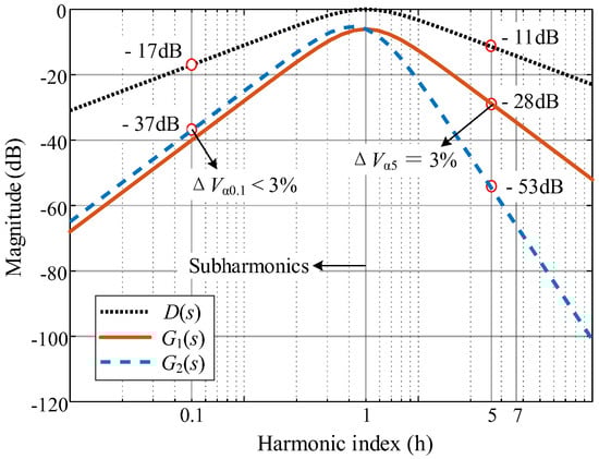
Figure 9.
Magnitude plot of low-frequency (LF) harmonics with k = 1.414 and ωg = 314 rad/s.
In all, this proposed voltage/frequency tracking method based on SOGIs has good features regarding subharmonics and dc bias rejection, as well as voltage/frequency capture in grid voltage serious oscillation. This method is thus suitable for a shipboard power system with new energy generation.
4.3. The Parameters Optimization Design of SOGI-FDE-FLL
There were four damping constants in four SOGIs and one error gain in FLL in SOGI-FDE-FLL. The values of those parameters have close relations to the characteristics of the structure.
4.3.1. The Characteristics of Damping Constant in SOGI
Figure 10 depicts the relationships of the ratios of in-phase voltage amplitude Vα and quadrature-phase voltage amplitude Vβ to input voltage amplitude, respectively, with their frequency ratio ω/ωg from 0.8 to 1.2 and damping constant k from 0.5 to 2, obtained from Equations (11)–(14) to emulate the grid voltage/frequency swing. The values of k have great effects on both the in-phase and quadrature-phase outputs, especially on the former when the input signal amplitude and frequency fluctuate. When ω is equal to the oscillation frequency ωg, Vα and Vβ are both equal to V, and at that time, from Equations (13) and (14), V can be deduced from
which means ωg is kept equal to ω, so the estimated amplitude can be obtained from SOGI’s in-phase and quadrature-phase signals.
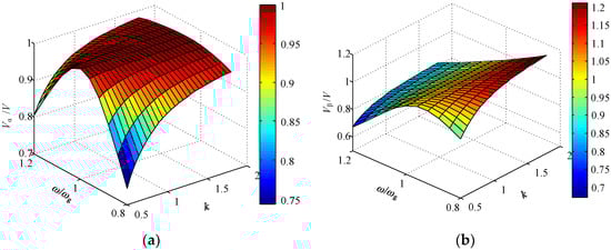
Figure 10.
Graph of Vα/V and Vβ/V in ω/ωg from 0.8 to 1.2 and the damping constant k from 0.5 to 2. (a) Graph of Vα/V, ω/ωg, and k. (b) Curve of Vβ/V, ω/ωg, and k.
Moreover, from the input-phase output-voltage curve shown in Figure 10a, it can be seen that
and Vα is increasingly smaller with decreasing k. The higher k is, the smaller the value of V minus Vα is. However, the quadrature-phase output voltage curve shown in Figure 10b had variation trends different from that shown in Figure 10a. When the input signal fluctuating with k was greater than 1, Vβ/V and ω/ωg had approximately linear relations and Vβ decreased as ω increased. The higher k is, the more this linearity improves.
The damping constant can be determined by the voltage variance from Figure 9, and was replotted to 2D as shown in Figure 11. Compared to Vβ, Vα had less voltage variance. Increasing k is of benefit for decreasing this variance. On the other hand, Vβ, as shown in Figure 10b, has relatively less variance when k is from 1.0 to 1.5 but tends to have proportional variance to the continuously increasing k. This linear relationship improves the stability in the transient response and can be expressed as
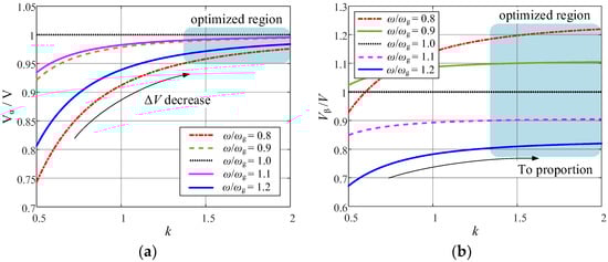
Figure 11.
Curves of Vα/V and Vβ/V vs. k with ω/ωg at 0.8, 0.9, 1.0, 1.1, and 1.2. (a) Curve of Vα/V. (b) Curve of Vβ/V.
Above all, the frequency variation of the input signal is the key point of amplitude variance generation in the in-phase and quadrature-phase outputs, and the damping constant is the key parameter for the SOGI unit, which directly affects the two output signals. Increasing the damping constant obviously decreased the amplitude variance of the in-phase output and improved the quadrature-phase output linearity, which is better for the stability of the transient response and voltage/frequency swing.
4.3.2. Three Damping Constants in SOGI-FDE Unit
The damping constant of the SOGI is also in direct relation to the bandwidth of the in-phase signal passing through. The higher the damping constant, the wider the frequency band signal passes through with worse harmonic attenuation; the lower damping constant represents a narrower bandwidth and better frequency selection, but worse stability.
For the proposed schematics of Figure 8, the inputs of SOGI I and II were directly connected to the grid voltage in the αβ-frame. Hence, k1 and k2, the corresponding damping constants of SOGI I and II, are key to the transmitting voltage bandwidth, letting k1 = k2 = k. The Chinese shipboard power system standard stipulates that the fundamental frequency of the vessel’s grid fo is (50 ± 5) Hz [10]. Hence, to ensure that the proposed PLL worked normally across a wide range, the frequency bandwidth ΔfBW of SOGI I and SOGI II should be set greater than 25 Hz, namely,
Meanwhile, for the dynamic response requirement of the SOGI unit in the SPS, the settling time should be limited to one fundamental period, namely,
from Equation (7).
Hence, for the furthest minimum, the in-phase output variance of SOGI I and II, shown in Figure 10a, that integrated Equations (27) and (28), k1 and k2 was set to 1.6. Similarly, SOGI III generated the positive rotation factor j with the quadrature-phase output. To obtain the minimum error shown in Figure 10b, and the optimal dynamic response, k3 was set to 1.2.
4.3.3. Damping Constant and Error Gain in SOGI-FLL Unit
For the bandwidth requirement, SOGI-FLL should have a narrow bandwidth when compared to SOGI I and II. Hence, the damping constant k4 should be set smaller than k1 and k2 from Equation (27). Let k4 equal the square root of 2 to obtain the best response as an optimum second order system.
In the mentioned shipboard PV–diesel-battery power system, grid voltage stability is regulated by the exciter system of the diesel-engine synchronous generator. However, due to the large inertia of the diesel engine, grid voltage was in LF fluctuation on a large-scale time span. Due to the SPS with the slack bus, the fast response of the PV–battery inverter did not benefit system stability. For a good tradeoff between the speed of adaptive frequency and the stability of the power system, the rising time of the frequency system (shown in Figure 4) was made greater than the time of the fundamental period. Hence, the error gain γ was namely deduced from Equation (19) as
Figure 12 depicts the voltage/frequency dynamic response of SOGI-FLL when k4 was equal to 1.414. When the grid frequency jumped from 50 to 55 Hz at 0.2 s, from 55 to 45 Hz at 0.35 s, and back to 50 Hz at 0.5 s; γ was equal to /2, /π, and ωo2/4, respectively. The corresponding frequency dynamic response is shown in Figure 12a, where γ is the key parameter. Higher γ brought about a short settling time with higher overshoot (see the curve of γ = ωo2/4), whereas a lower γ obtained good stability without overshoot, but had a longer settling time, as depicted in the curve of γ = ωo2/2 with a 50 ms settling time. When γ was ωo2/π, it showed good dynamic characteristics without overshoot and good stability. The optimal value of γ is namely
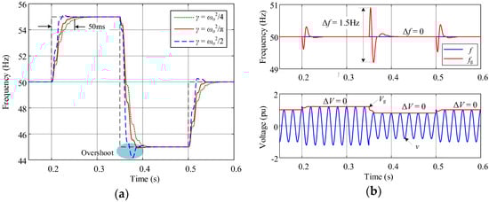
Figure 12.
Voltage/frequency dynamic response of SOGI-FLL when damping constant is 1.414. (a) Frequency step dynamic response at different γ values. (b) Voltage/frequency transient response in amplitude step when γ = /π.
Figure 12b shows the estimated amplitude and frequency transient response of SOGI-FLL when the input signal’s amplitude jumped from 1 to 1.2 per unit, or pu, at 0.2 s, from 1.2 to 0.8 pu at 0.35 s, and back to 1 pu at 0.5 s in γ = /π. In this plot, we can see that Vg was equal to V, and fg was constant regardless of whether V changed or not, which means that V cannot affect Vg and fg in steady states, which made the grid voltage V and frequency f have good consistency when the voltage/frequency was in swing. Moreover, fg had a slight fluctuation of 1.5 Hz and less than 50 ms settling time, about two grid periods. Vg could smoothly shift in one grid period without oscillation.
5. Experiment and Discussion
Experimental results were obtained for a shipboard PV–diesel-battery hybrid power system where a PV–battery inverter generated a sinusoidal current synchronous to the positive sequence grid voltage. These results validated the proposed SOGI-based voltage/frequency tracking scheme in a practical shipboard power system with adverse grid conditions.
5.1. Experimental Setup
To confirm the theoretical analysis presented, the experimental setup of the shipboard PV–diesel-battery hybrid power system considered in this work is shown in Figure 13. It included a dc programmable source configured to emulate the PV–battery (TC.P.16.1000.400.S, Regatron, Rorschach, Switzerland), a 2.2 kVA Danfoss three-phase inverter, and a programmable three-phase voltage source (61511, Chroma, Taoyuan, Taiwan) to emulate the shipboard grid and obtain repetitive unbalance faults with harmonics and dc offset. The setup used a digital control platform based on dSPACE (1007, dSPACE, Paderborn, Germany) to realize the proposed SOGI-based voltage/frequency tracking schematic and droop control strategies. The setup parameters are shown in Table 1.
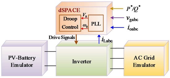
Figure 13.
Experimental setup.

Table 1.
Parameters of the experimental setup.
5.2. Experimental Results and Discussion
The pre-fault grid voltages were Va = 220∠0° V, Vb = 220∠−120° V, and Vc = 220∠120° V. The SPS grid voltages under adverse conditions consisted of 90% positive and 20% negative sequence components, namely Va = 242∠0° V, Vb = 180.4∠−132° V, and Vc = 180.4∠132° V with 22 V, −11 V, and −11 V dc bias values, respectively, including low-order harmonics content (5% 5th and 5% 7th harmonics) to emulate the most serious situations, which led to a measured voltage THD in the pre-fault of 6.43% and 10.10% for the α and β frames, respectively. The programmed voltage swing of ±20% and frequency oscillation of ±20% is shown in Figure 14 to emulate the adverse grid voltage of SPS in load transient for its power limitation.
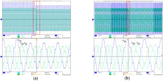
Figure 14.
Measured grid voltage emulator under adverse conditions: (a) Adverse grid voltage in voltage swing at 220 and 176 V: (top) 100 V/div, 100 ms/div; (bottom) 100 V/div, 10 ms/div. (b) Adverse grid voltage in frequency swing at 60 and 40 Hz: (top) 100 V/div, 200 ms/div; (bottom) 100 V/div, 10 ms/div.
The parameters of this proposed adaptive grid voltage/frequency tracking schematic based on SOGIs to the shipboard PV–diesel-battery hybrid power system, shown in Figure 8, were optimized and are listed in Table 2.
Table 2.
Parameters of the proposed SOGI-based voltage/frequency tracking schematic.
Figure 15 shows the grid voltage amplitude and frequency tracking transient response in the emulated adverse grid. Figure 15a,b depict the dynamic response of the locked amplitude Vg and frequency fg in amplitude transient and show the filtered positive sequence of grid voltage in the αβ-frame with good quality without dc offset and harmonics. Note that the proposed SOGI-FDE-PLL could filter dc bias and harmonics and extract a 0.9 pu positive sequence voltage. The estimated grid voltage amplitude Vg presented a fast response in one fundamental period without overshoot and had smooth dynamic features, whereas fg had oscillation in 0.25 Hz and the settling time was 2~3 periods, which can be neglected for the SPS with a ±5% fluctuation permit. Figure 15c,d depict the dynamic response of Vg and fg in the alternative frequencies of 40 and 60 Hz, as well as the smoothly positive sequence of the grid voltage. The locked frequency fg had a smooth response with a 0.5 ms settling time without any fluctuations that have adaptive features of auto-adjustment, whereas the locked voltage Vg oscillated with an 0.2 pu voltage deviation in approximately two periods settling time. For the low capacity of the PV–battery inverter when compared to the diesel generation system, this voltage deviation in two periods had little effect on the grid voltage. Hence, the proposed SOGI-FDE-FLL can capture grid voltage amplitude and frequency accurately and quickly in the vessel’s power quality problems of serious voltage/frequency swing, unbalanced voltage, subharmonic/dc-offset voltage, and LF/HF harmonics.
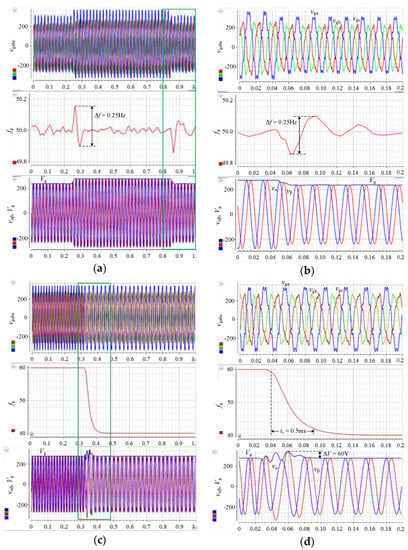
Figure 15.
Experimental voltage tracking results of the proposed SOGI-FDE-FLL in the emulated adverse grid: (a,b) Locked amplitude Vg and frequency fg, as well as the filtered positive sequence voltage vαβ dynamic response in the voltage amplitude alternatively varying between 1 pu and 0.8 pu; (c,d) The Vg, fg, and vαβ dynamic response in the frequency transient from 40 to 60 Hz.
The emulated shipboard PV–diesel-battery hybrid power system (see Figure 13) was set up to test the validity of the proposed method. Figure 16 depicts the details of the emulated grid voltage vgabc and the a-phase injection-current ioa of the PV–battery inverter in rated power at a steady state. The THD of this obtained current was 2.05% (<3%) with higher quality, although the shipboard grid had more power quality issues of unbalanced voltage, subharmonic/dc-offset voltage, and LF/HF harmonics.
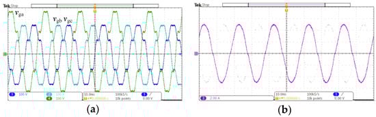
Figure 16.
Measured grid voltage and injection currents of the PV–battery inverter in a steady state: (a) the emulated adverse grid voltage: 100 V/div, 10 ms/div; (b) the corresponding a-phase injection current ioa of the inverter: 2 A/div, 10 ms/div.
6. Conclusions
In this paper, a kind of shipboard PV–diesel-battery power system structure was chosen, where the diesel-engine synchronous generator worked in standalone mode as a slack bus to maintain the grid voltage frequency and amplitude. PQ control was adopted for the PV–battery inverter, and the integrated power droop control strategy was established. Based on this SPS, an adaptive grid voltage/frequency tracking configuration (SOGI-FDE-FLL) was proposed for unbalanced voltage, subharmonic/dc-offset voltage, and LF/HF harmonic conditions. An experimental setup was established. When the emulated grid had an unbalanced voltage with 0.2 pu negative component with a 20% voltage swing and frequency oscillation including the 0.05 pu dc bias, 5th and 7th LF harmonics separately, the positive sequence voltage amplitude and frequency could be obtained precisely with a 2~3-period step response. Moreover, the captured voltage amplitude has consistence to the grid voltage amplitude envelope curve. Hence, the experimental results testified that the proposed SOGI-FDE-FLL could capture the grid voltage amplitude and frequency accurately and quickly. This proposed grid voltage/frequency tracking method based on SOGIs has a simple structure, tracks transient and accurate grid voltage/frequency, and has good prospects for vessels applying photovoltaic power generation technology.
Acknowledgments
The authors are grateful to the Editor who handled this paper and two anonymous reviewers for constructive suggestions with regard to the revised draft. The authors gratefully acknowledge the support from the Key Project of Fujian Natural Foundation (JZ160451), the National Natural Science Foundation General Project (51679106), and the Natural Science Foundation of Fujian Province (2017J01703).
Author Contributions
Guoling Wang and Xu Liu conceived and designed the experiments; Guoling Wang and Zhenyu Li performed the experiments; Zhe Chen provided helpful discussions on the experiment design; Guoling Wang and Shunxiao Xu analyzed the data; Guoling Wang wrote the paper.
Conflicts of Interest
The authors declare no conflict of interest.
References
- Geertsma, R.D.; Negenborn, R.R.; Visser, K.; Hopman, J.J. Design and control of hybrid power and propulsion systems for smart ships: A review of developments. Appl. Energy 2017, 194, 30–54. [Google Scholar] [CrossRef]
- Shagar, V.; Jayasinghe, S.G.; Enshaei, H. Effect of Load Changes on Hybrid Shipboard Power Systems and Energy Storage as a Potential Solution: A Review. Inventions 2017, 2, 21. [Google Scholar] [CrossRef]
- Oh, K.G.; Moon, B.Y.; Lee, K.Y. Performance Evaluation and Technical Development of Eco-environmental Photovoltaic Leisure Ship with Sail-controlling Device With Respect to Solar-Hybrid Generating System. J. Ocean Eng. Technol. 2016, 30, 57–67. [Google Scholar] [CrossRef]
- Ghenai, C.; Salameh, T.; Merabet, A.; Hamid, A.K. Modeling and optimization of hybrid solar-diesel-battery power system. In Proceedings of the 2017 7th International Conference on Modeling, Simulation, and Applied Optimization (ICMSAO), Sharjah, UAE, 4–6 April 2017; pp. 1–5. [Google Scholar]
- Nojavan, S.; Majidi, M.; Zare, K. Risk-based optimal performance of a PV/fuel cell/battery/grid hybrid energy system using information gap decision theory in the presence of demand response program. Int. J. Hydrogen Energy 2017, 42, 11857–11867. [Google Scholar] [CrossRef]
- Wen, S.; Lan, H.; Yu, D.C.; Fu, Q.; Hong, Y.-Y.; Yu, L.; Yang, R. Optimal sizing of hybrid energy storage sub-systems in PV/diesel ship power system using frequency analysis. Energy 2017, 140, 198–208. [Google Scholar] [CrossRef]
- Guerrero, J.M.; Jin, Z.; Liu, W.; Othman, M.B.; Savaghebi, M.; Anvari-Moghaddam, A.; Meng, L.; Vasquez, J.C. Shipboard Microgrids: Maritime Islanded Power Systems Technologies. In Proceedings of the International Exhibition and Conference for Power Electronics, Intelligent Motion, Renewable Energy and Energy Management (PCIM Asia 2016), Shanghai, China, 28–30 June 2016; pp. 1–8. [Google Scholar]
- Cohen, I.J.; Westenhover, C.S.; Wetz, D.A.; Heinzel, J.M.; Dong, Q. Evaluation of an actively contolled battery-capacitor hybrid energy storage module (HESM) for use in driving pulsed power applications. In Proceedings of the 2015 IEEE Pulsed Power Conference (PPC), Austin, TX, USA, 31 May 2015–4 June 2015; pp. 1–5. [Google Scholar]
- Li, Y.; Peng, Y.; Liu, F.; Sidorov, D.; Panasetsky, D.; Liang, C.; Luo, L.; Cao, Y. A controllably inductive filtering method with transformer-integrated linear reactor for power quality improvement of shipboard power system. IEEE Trans. Power Deliv. 2017, 32, 1817–1827. [Google Scholar] [CrossRef]
- China Classification Society. Classification Rules of Steel Sea-Going Vessel; China Communications Press: Beijing, China, 2015. [Google Scholar]
- Trinh, Q.N.; Choo, F.H.; Wang, P. Control Strategy to Eliminate Impact of Voltage Measurement Errors on Grid Current Performance of Three-Phase Grid-Connected Inverters. IEEE Trans. Ind. Electron. 2017, 64, 7508–7519. [Google Scholar] [CrossRef]
- Feng, X.; Butler-Purry, K.L.; Zourntos, T. A Multi-Agent System Framework for Real-Time Electric Load Management in MVAC All-Electric Ship Power Systems. IEEE Trans. Power Syst. 2015, 30, 1327–1336. [Google Scholar] [CrossRef]
- Golestan, S.; Ramezani, M.; Guerrero, J.M.; Freijedo, F.D.; Monfared, M. Moving average filter based phase-locked loops: Performance analysis and design guidelines. IEEE Trans. Power Electron. 2014, 29, 2750–2763. [Google Scholar] [CrossRef]
- Wang, J.; Liang, J.; Gao, F.; Zhang, L.; Wang, Z. A method to improve the dynamic performance of moving average filter-based PLL. IEEE Trans. Power Electron. 2015, 30, 5978–5990. [Google Scholar] [CrossRef]
- Khazraj, H.; da Silva, F.F.; Bak, C.L.; Golestan, S. Analysis and design of notch filter-based PLLs for grid-connected applications. Electr. Power Syst. Res. 2017, 147, 62–69. [Google Scholar] [CrossRef]
- Golestan, S.; Ramezani, M.; Guerrero, J.M.; Monfared, M. dq-frame cascaded delayed signal cancellation-based PLL: Analysis, design, and comparison with moving average filter-based PLL. IEEE Trans. Power Electron. 2015, 30, 1618–1632. [Google Scholar] [CrossRef]
- Xiao, F.; Dong, L.; Li, L.; Liao, X. A Frequency-Fixed SOGI-Based PLL for Single-Phase Grid-Connected Converters. IEEE Trans. Power Electron. 2017, 32, 1713–1719. [Google Scholar] [CrossRef]
- Bendrat, F.; Chhor, J.; Sourkounis, C. Novel computation-efficient three-phase EPLL-based grid synchronization techniques considering power quality issues. In Proceedings of the 2017 25th Mediterranean Conference on Control and Automation (MED), Valletta, Malta, 3–6 July 2017; pp. 787–793. [Google Scholar]
- Patel, S.K.; Arya, S.R.; Maurya, R.; Jain, C.; Singh, B. Control of distributed static compensator using extended structure-enhanced phase-locked loop-based algorithm under nonideal AC mains. Int. Trans. Electr. Energy Syst. 2017, 27. [Google Scholar] [CrossRef]
- Yada, H.K.; Murthy, M. An improved control algorithm for DSTATCOM based on single-phase SOGI-PLL under varying load conditions and adverse grid conditions. In Proceedings of the 2016 IEEE International Conference on Power Electronics, Drives and Energy Systems (PEDES), Trivandrum, India, 14–17 December 2016; pp. 1–6. [Google Scholar]
- Yi, H.; Wang, X.; Blaabjerg, F.; Zhuo, F. Impedance Analysis of SOGI-FLL-Based Grid Synchronization. IEEE Trans. Power Electron. 2017, 32, 7409–7413. [Google Scholar] [CrossRef]
- Karbasforooshan, M.-S.; Monfared, M. Design and Implementation of a Single-Phase Shunt Active Power Filter Based on PQ Theory for Current Harmonic Compensation in Electric Distribution Networks. In Proceedings of the 43rd Annual Conference of the IEEE Industrial Electronics Society (IECON 2017), Beijing, China, 29 October–1 November 2017; pp. 6389–6394. [Google Scholar]
- Shin, K.-H.; Hwang, S.-H.; Lee, J.S. Analysis of an offset error on a single-phase grid-connected inverter based on a proportional-resonant controller. In Proceedings of the 2017 IEEE Applied Power Electronics Conference and Exposition (APEC), Tampa, FL, USA, 26–30 March 2017; pp. 2615–2617. [Google Scholar]
- Sun, Q.; Guerrero, J.M.; Jing, T.; Vasquez, J.C.; Yang, R. An islanding detection method by using frequency positive feedback based on FLL for single-phase microgrid. IEEE Trans. Smart Grid 2017, 8, 1821–1830. [Google Scholar] [CrossRef]
- Pavković, D.; Kristović, P.; Hrgetić, M.; Komljenović, A.; Užarević, V. Single phase AC inverter current PR control with auxiliary PI controller for DC current suppression. In Proceedings of the IEEE EUROCON 2017-17th International Conference on Smart Technologies, Ohrid, Macedonia, 6–8 July 2017; pp. 324–329. [Google Scholar]
© 2018 by the authors. Licensee MDPI, Basel, Switzerland. This article is an open access article distributed under the terms and conditions of the Creative Commons Attribution (CC BY) license (http://creativecommons.org/licenses/by/4.0/).