Article

A High-Gain Reflex-Based Bidirectional DC Charger with Efficient Energy Recycling for Low-Voltage Battery Charging-Discharging Power Control

1
Department of Vehicle Engineering, National Taipei University of Technology, No. 1, Sec. 3, Chung-Hsiao E. Road, Taipei 106, Taiwan
2
Graduate Institute of Mechanical and Electrical Engineering, National Taipei University of Technology, No. 1, Sec. 3, Chung-Hsiao E. Road, Taipei 106, Taiwan
3
Department of Information and Communication Engineering, Chaoyang University of Technology, Taichung 41349, Taiwan
4
School of Electrical and Electronic Engineering, Universiti Sains Malaysia, Engineering Campus, Nibong Tebal 14300, Malaysia
*
Author to whom correspondence should be addressed.
Energies 2018, 11(3), 623; https://doi.org/10.3390/en11030623
Submission received: 17 February 2018 / Revised: 8 March 2018 / Accepted: 8 March 2018 / Published: 11 March 2018
(This article belongs to the Special Issue Power Electronics in DC-Microgrid Systems)

Abstract

:
This study proposes a high-gain reflex-charging-based bidirectional DC charger (RC-BDC) to enhance the battery charging efficiency of light electric vehicles (LEV) in a DC-microgrid. The proposed charger topology consists of an unregulated level converter (ULC) and a two-phase interleaved buck-boost charge-pump converter (IBCPC), which together provide low ripple and high voltage conversion ratio. As the high-gain RC-BDC charges, the LEV’s battery with reflex charging currents, high battery charging efficiency, and prolonged battery life cycles are achieved. This is possible due to the recovering of negative pulse energy of reflex charging currents to reduce charge dissipations within LEV’s batteries. Derivations of the operating principles of the high-gain RC-BDC, analyses of its topology, and the closed-loop control designs were presented. Simulations and experiments were implemented with battery voltage of 48 V and DC-bus voltage of 400 V for a 500 W prototype. The results verify the feasibility of the proposed concept and were compared with the typical constant-current/constant-voltage (CC/CV) charger. The comparison shows that the proposed high gain RC-BDC improves battery charging speed and reduces the battery thermal deterioration effect by about 12.7% and 25%, respectively.

1. Introduction

The advent of new technologies have cultivated new economic activities that demand more electricity, and, for this reason, maintaining and supplying high power quality is more important than ever before [1,2,3,4,5]. At the same time, new requirements for environmental conservation and reducing carbon footprints, which contradict the need for more power, has also been initiated in many countries. As a result, generators are sandwiched between their roles to produce more power and reduce greenhouse gas emissions. An increasingly popular solution is to implement the DC-microgrid which has widely been accepted to consist of distributed clean energies, including wind and solar, battery energy storage (BES) systems that help to satisfy electricity demand and offset shortages from renewables and electric vehicles (EV) with bidirectional power flow feature—vehicle-to-grid (V2G) and grid-to-vehicle (G2V) [5,6,7,8]. Various studies have shown that the operation of the DC-microgrid lead to the overall reduction of carbon emissions without sacrificing power demands [1,2,3,4]. The bidirectional power flow capability of EVs is one of the most critical aspects of the DC-microgrid. It enables the complete use of the internal battery stack of the EVs and employ them as mobile energy storage units. EVs are normally charged during off-peak hours when they are also least used, and are discharged into the grid at higher on-peak rates.
Moving forward, the size of the conventional EVs has shrunken typically to between a car and motorcycle—known as the light electric vehicle (LEV). The LEV’s battery voltage requirements depend on the motor power but are normally rated at 24 V, 48 V, 72 V, and 96 V. On the other hand, the DC-bus is rated rather high at around 380 ± 20 V [9,10,11,12]. Hence, in order to facilitate the operations of LEVs, a high-gain bidirectional converter, serving as the power electronic interface between LEVs and the DC-microgrid, is needed. Conventionally, this has been achieved using the constant-current/voltage (CC/CV) charging process [12,13]. But, this process is latent with the problems of incomplete reaction, excessive thermal rise, and short battery life cycle due to the persistent charging cycle. An alternative is to use the Reflex-charging control strategy [14,15,16,17,18]. This relatively new method employs high level currents to speed up charging and both the negative pulse period (NPP) and the short resting period (RP) in each charging cycle. The combination of both the NPP and RP are able to reduce the internal resistance of the battery, suppress bubble formations and pressure inside the cell, and remove impurities on battery electrodes. Consequently, unwanted chemical reactions are reduced and the battery charging process are optimized.
It has been identified that the battery energy absorption rate during NPP is the main factor that influences the battery charging efficiency; the higher the rate, the better it is. A non-dissipative passive circuit has been proposed to achieve this objective [19], but the wastage of energy and increase in design cost outweighs its benefits.
In this paper, a reflex-charging-based bidirectional DC charger (RC-BDC) is proposed and its high-gain bidirectional converter topology is adopted from [20]. Despite such combination was briefly presented in [21], factors such as efficient energy recycling characteristics and system behaviors were never thoroughly analyzed. Moreover, the main difference of our proposed RC-BDC is the inclusion of a closed-loop control design procedure. This is the first time that such combination is considered. When the proposed RC-BDC is connected to the DC-microgrid, the DC-bus can charge the relatively low voltage battery using the reflex-charging control strategy. In addition, the battery energy is returned to the DC-bus during NPP. Based on these, a 500-W high-gain RC-BDC prototype is built and tested using reflex-charging and constant-current discharging controls. The test results verify the feasibility of the proposed concept.

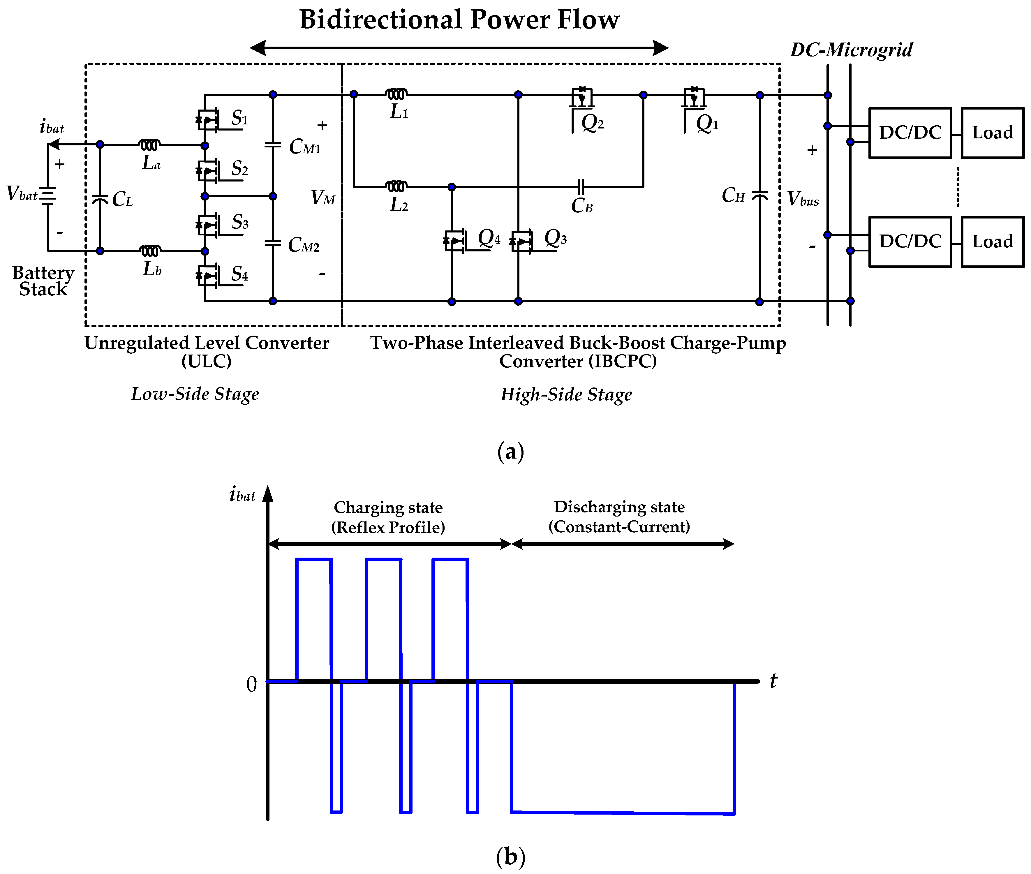
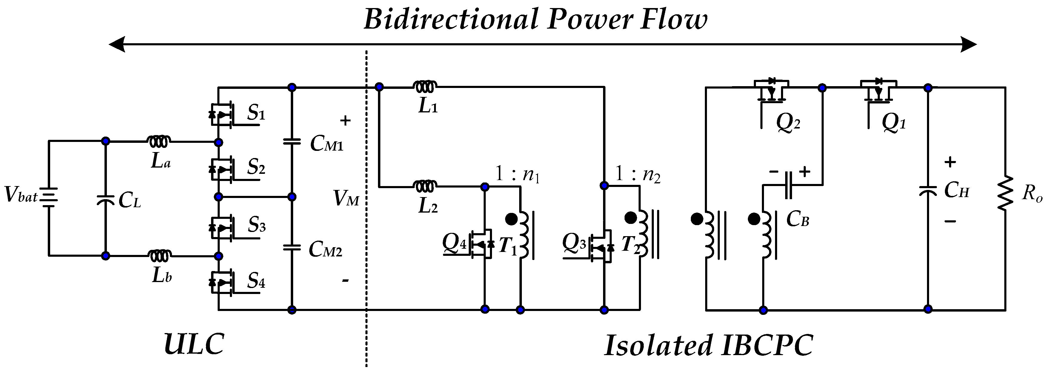
2. Operation Principles of the Proposed High-Gain RC-BDC

The converter topology of the proposed RC-BDC is shown in Figure 1a [20,21], where Vbus and Vbat are the DC-bus voltage and battery voltage on the high and low sides, respectively; iL1 and iL2 are the phase currents of the interleaved charge-pump converter (IBCPC), and iLt is the sum of iL1 and iL2; CB is the charge-pump capacitance; CH and CL denote the capacitance on the high and low sides, respectively; Q1Q4 and S1S4 are the power switches of the IBCPC and the unregulated level converter (ULC), respectively; D denotes the active switch duty cycle of the charging and discharging states; La and Lb are the high-frequency filtering inductance; and, CM1, CM2 are DC-link capacitors. The ULC charges and discharges the battery with a conversion ratio of 2:1 (voltage-dividing) and 1:2 (voltage doubling). The IBCPC is used for bidirectional power flow control at high voltage conversion ratios (i.e., high-voltage 380 ± 20 V; low-voltage: 44–56 V).
The battery current waveforms of the proposed RC-BDC are shown in Figure 1b and Figure 2. Figure 1b shows that the reflex-charging control strategy is used to charge the battery, where battery is rapidly charged during positive pulse periods (PPP) and are followed by NPPs when battery energy is returned to the DC-bus. The purpose of adding a negative pulse after the PPP is to reduce the generation of bubbles and excessive pressure inside the battery, as well as to suppress the influence of impurities attached on the electrode plates during the chemical reaction. Finishing both the PPP and NPP is considered to be a complete cycle. A sufficient resting period (RP) is given after each cycle and this is the time when electrolytic solution is diffused and neutralized. Due to this, the conversion efficiency from electrical to chemical energy is enhanced and battery temperature rise is limited, further increasing the battery lifetime. The proposed RC-BDC is also able to return battery energy to the DC-microgrid by reversing the power flow in a constant-current manner; the discharging capability of the converter.
The details of the PPP is given below:
Mode 1 (t0 < t ≤ t1): Q1 and Q3 are turned on, whereas Q2 and Q4 are turned turn off; S1 and S3 are turned on, whereas S2 and S4 are turned off. The voltage across inductor L1 is negative, and iL1 linearly decreases. The voltage across inductor L2 can be obtained by subtracting the charge-pump voltage VCB and VM from the high-side voltage Vbus, and its slope is expressed as (Vbus/2 − VM)/L2.
Mode 2 (t1 < t ≤ t2): Q3 and Q4 are turned on, whereas Q1 and Q2 are turned off; S1 and S3 are turned on, whereas S2 and S4 are turned off. The voltage across inductors L1 and L2 are negative, and thus, both iL1 and iL2 linearly decrease. Their current slopes are expressed as (−VM)/L1 and (−VM)/L2, respectively.
Mode 3 (t2 < t ≤ t3]: Q2 and Q4 are turned on, whereas Q1 and Q3 are turned off; S1 and S3 are turned on, whereas S2 and S4 are turned off. The voltage across inductor L1 is equal to the difference between the charge-pump voltage VCB and VM, and its slope is (Vbus/2 − VM)/L1.
Mode 4 (t3 < t ≤ t4): The state of the converter is the same as that of Mode 2.
During the PPP, the battery current ibat can be expressed as
i b a t = 2 i L t
The details of the NPP is given below:
Mode 1 (t5 < t ≤ t6): Under this mode, Q3 and Q4 are open, whereas Q1 and Q2 are closed; S2 and S4 are open, whereas S1 and S3 are closed.
The voltage across inductors L1 and L2 linearly increase, which is representative of energy storage. Their current slopes are expressed as (−VM)/L1 and (−VM)/L2, respectively.
Mode 2 (t6 < t ≤ t7): Under this mode, Q1 and Q3 are open, whereas Q2 and Q4 are closed; S2 and S4 are open, whereas S1 and S3 are closed. The period of this mode is (1 − Db)TSW.
The voltage across inductor L1 is positive, and iL1 linearly increases. The voltage across inductor L2 can be obtained by subtracting the charge pump voltage VCB and VM from the high-side voltage VH, and its slope is expressed as (VH/2 − VM)/L2.
Mode 3 (t7 < t ≤ t8): Under this mode, the converter works in the same way as in Mode 1.
Mode 4 (t8 < t ≤ t9): Under this mode, Q1 and Q3 are open, whereas Q2 and Q4 are closed; S2 and S4 are open, whereas S1 and S3 are closed.
There is a positive voltage across the converter inductor L2. The voltage across inductor L1 is equal to the difference between the charge pump voltage VCB and VM, and its slope is (VCB − VM)/L1.
For the discharging state, when the DC-bus voltage of the grid is lower than a preset value, the charger will automatically switch to the discharging state.
During this time, the converter works as a discharger with voltage-boosting function. This implies that the battery at the low-voltage side feeds the DC-bus with constant-current.

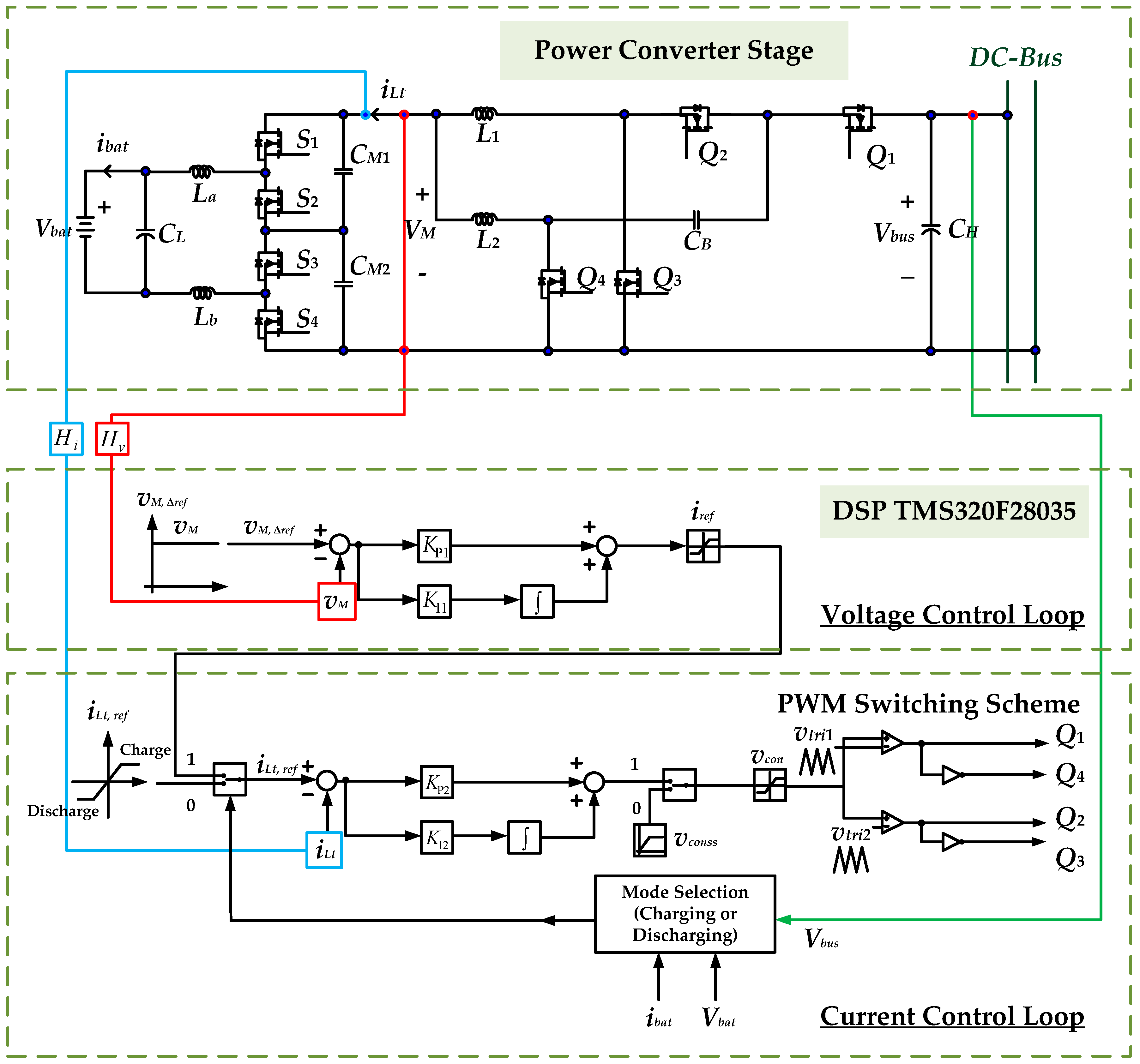
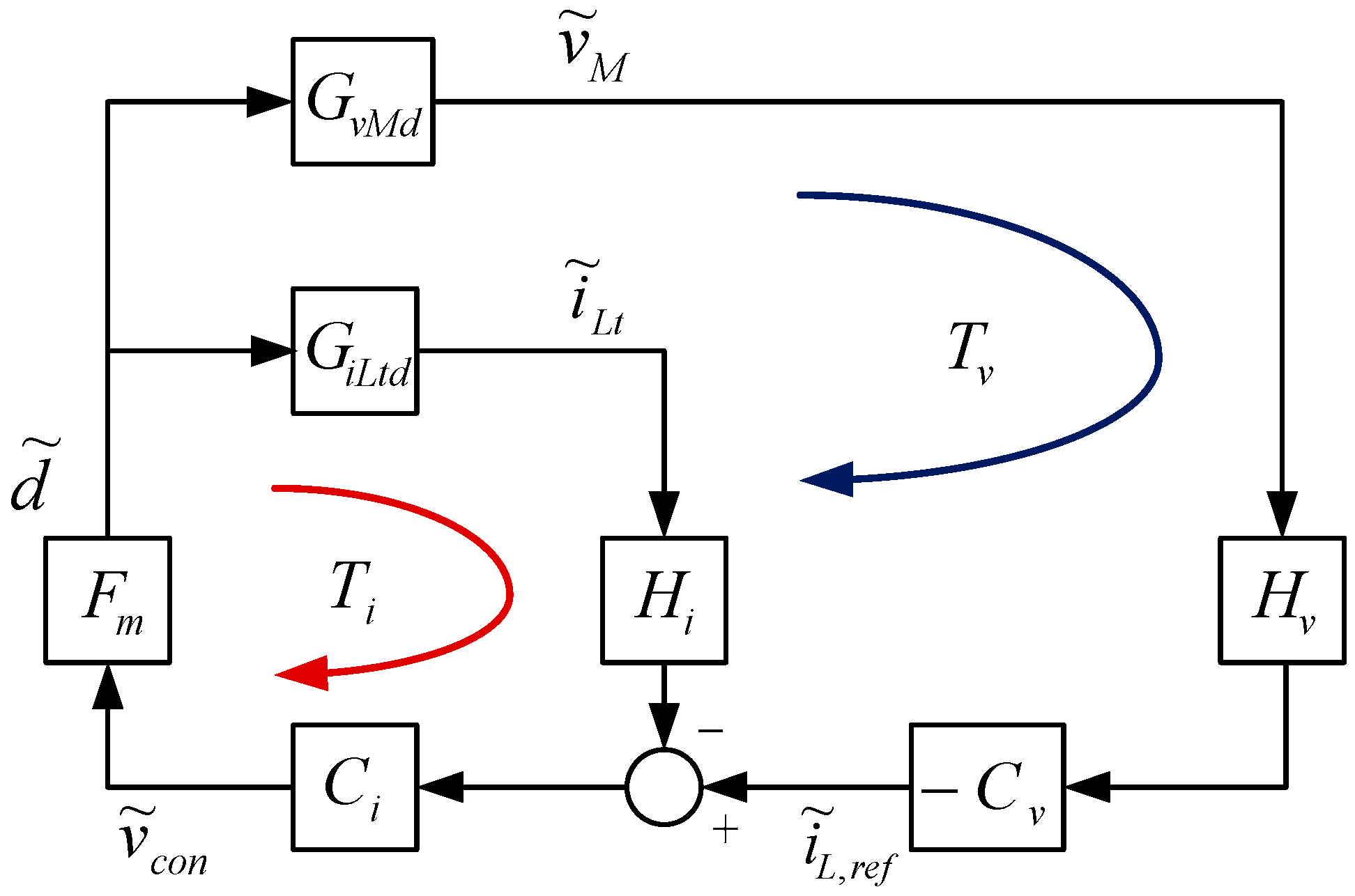
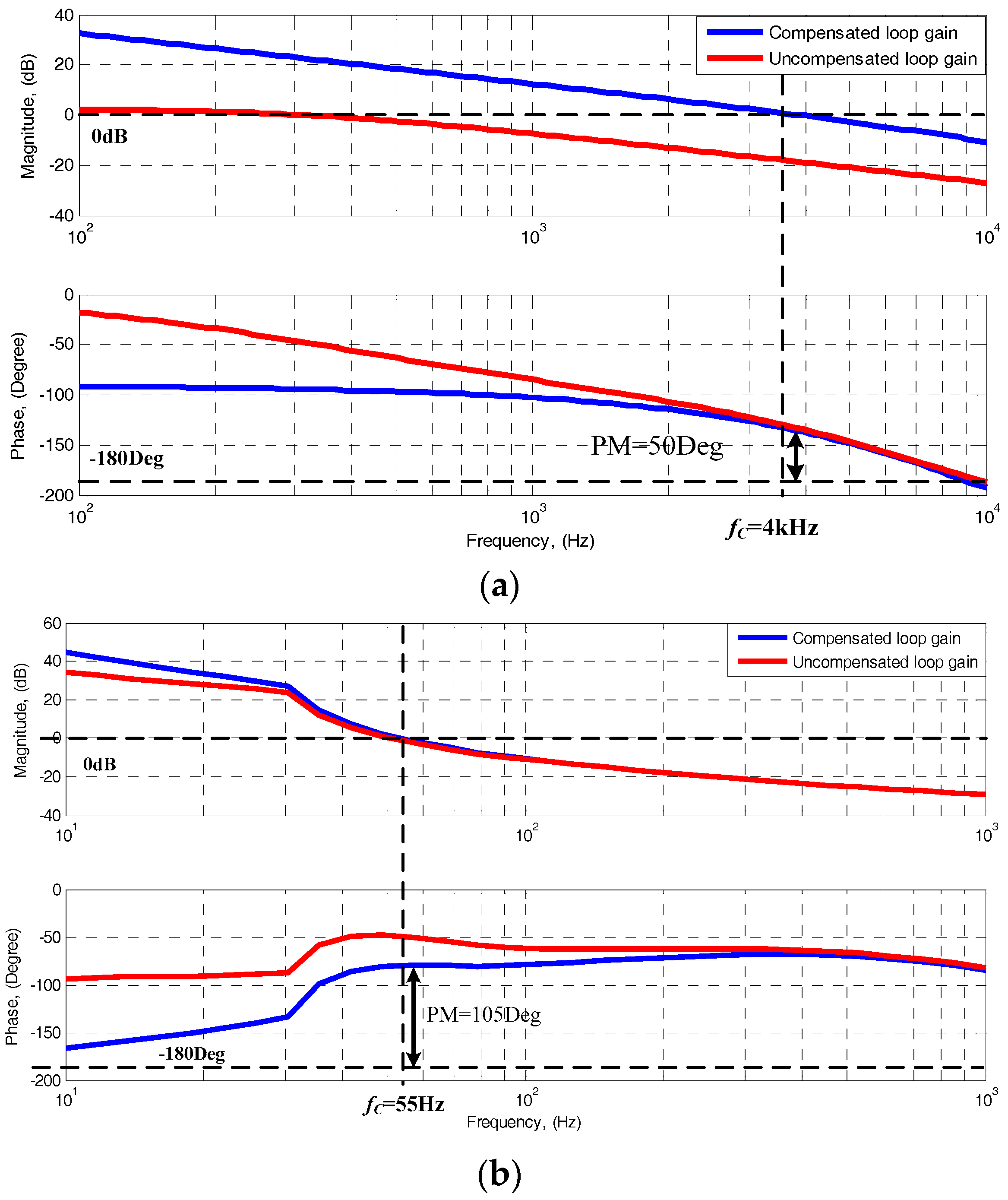
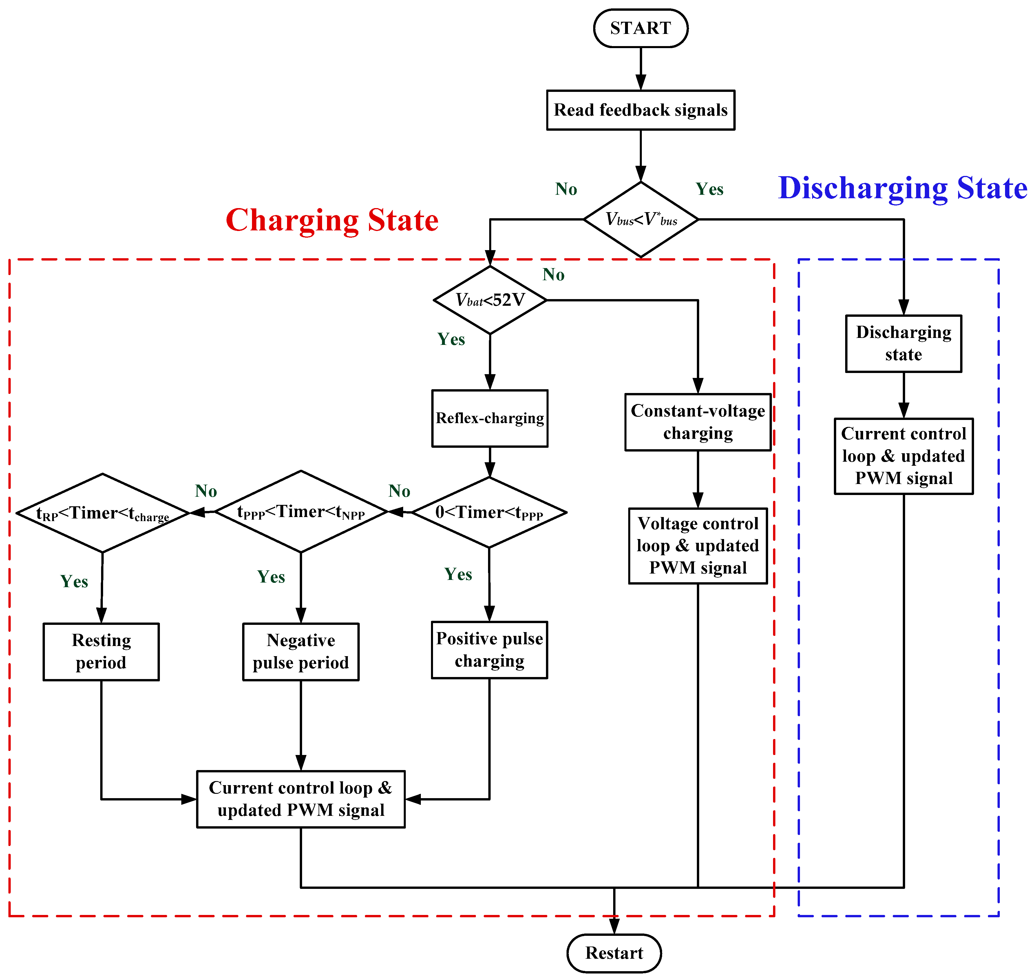
3. Controller Descriptions of the Proposed High-Gain RC-BDC

PSIM© simulation software (Powersim Inc., Rockville, MD, USA) was used to design the closed-loop controller with the following assumptions:
(1)
power switches and diodes are ideal;
(2)
equivalent series resistances (ESRs) of all the inductors and capacitors of the converter have precise dynamic model; and,
(3)
the converter works under continuous conduction mode (CCM) and ESRs (rL1 = rL2 = 180 mΩ; rCH = rCL = rCB = 60 mΩ). The circuit parameters for 500 W rating are L1 = L2 = 800 μH, CL = CH = 100 μF, CB = 10 μF.
Figure 3 illustrates the developed control system for the high-gain RC-BDC. The figure shows that the output voltage (Vbus), battery current (ibat) and battery voltage (Vbat) are monitored to determine the converter operating mode.
The middle voltage controller produces the total inductor reference current (iLt, ref) for the entire system. The equal current sharing between the two interleaved phases are also obtained here. During the system startup, soft start (Vconss) is used to avoid capacitor charge surge that can produce the current that damage the converter components.
The Block diagram of the closed-loop control scheme is shown in Figure 4. In the inner current control loop, FM is the constant gain of the PWM generator; GiLtd is the transfer function from the duty ratio to the total inductor current (iLt); Ci indicates the transfer function of current controllers; and, Hi is the sensing gain of the current sensor. In the outer voltage control loop, Gvd is the transfer function from the duty ratio to the middle-link voltage (VM); Cv indicates the transfer function of output voltage controller; and, Hv indicates the sensing gain of the voltage sensor.
From Figure 4, the gains from current and voltage loops are described by Equations (2) and (3), respectively.
T i ( s ) = F m H i G i L t d ( s ) C i ( s )
T v ( s ) = G v M d ( s ) H i H v G i L t d ( s ) H i T i ( s ) 1 + T i ( s ) C v ( s )
where, FM = 1/100, Hi = Hv = 1.
The small-signal transfer from the duty ratio to inductor current GiLtd is given by Equation (4) and the duty ratio to middle-link voltage GvMd is given by Equation (5).
G i L t d ( s ) = i ˜ L t ( s ) d ˜ ( s ) = C B α + σ s C B β + 2 λ
G v M d ( s ) = v ˜ M ( s ) d ˜ ( s ) = C M s + 1 s C B β + 2 λ
where, FM = 1/100, Hi = Hv = 1.
α = ( L 1 s D R C B + R L 1 + R C B ) ( V H + 2 I L 2 R C B )
β = ( L 1 s D R C B + R L 1 + R C B ) ( L 2 s D R C B + R L 2 + R C B )
λ = ( 1 D ) 2 ( L 2 s D R C B + R L 2 + R C B )
σ = 2 ( 1 D ) 2 ( V H + 2 I L 2 R C B )
The corresponding current/voltage controllers of the proposed high-gain RC-BDC are selected, as follows:
{ C i ( s ) = 20000 s + 2000 s ( s + 20000 ) C v ( s ) = 4 s + 200 s
Figure 5a,b show the loop gain frequency response of the compensated current and voltage loops under the full-load condition, respectively. The analyses indicate that 50-degree phase margin and 4-kHz crossover frequency are suitable for the compensated current loop, while the compensated voltage loop is most suitable with 105-degree phase margin and 55 Hz crossover frequency.

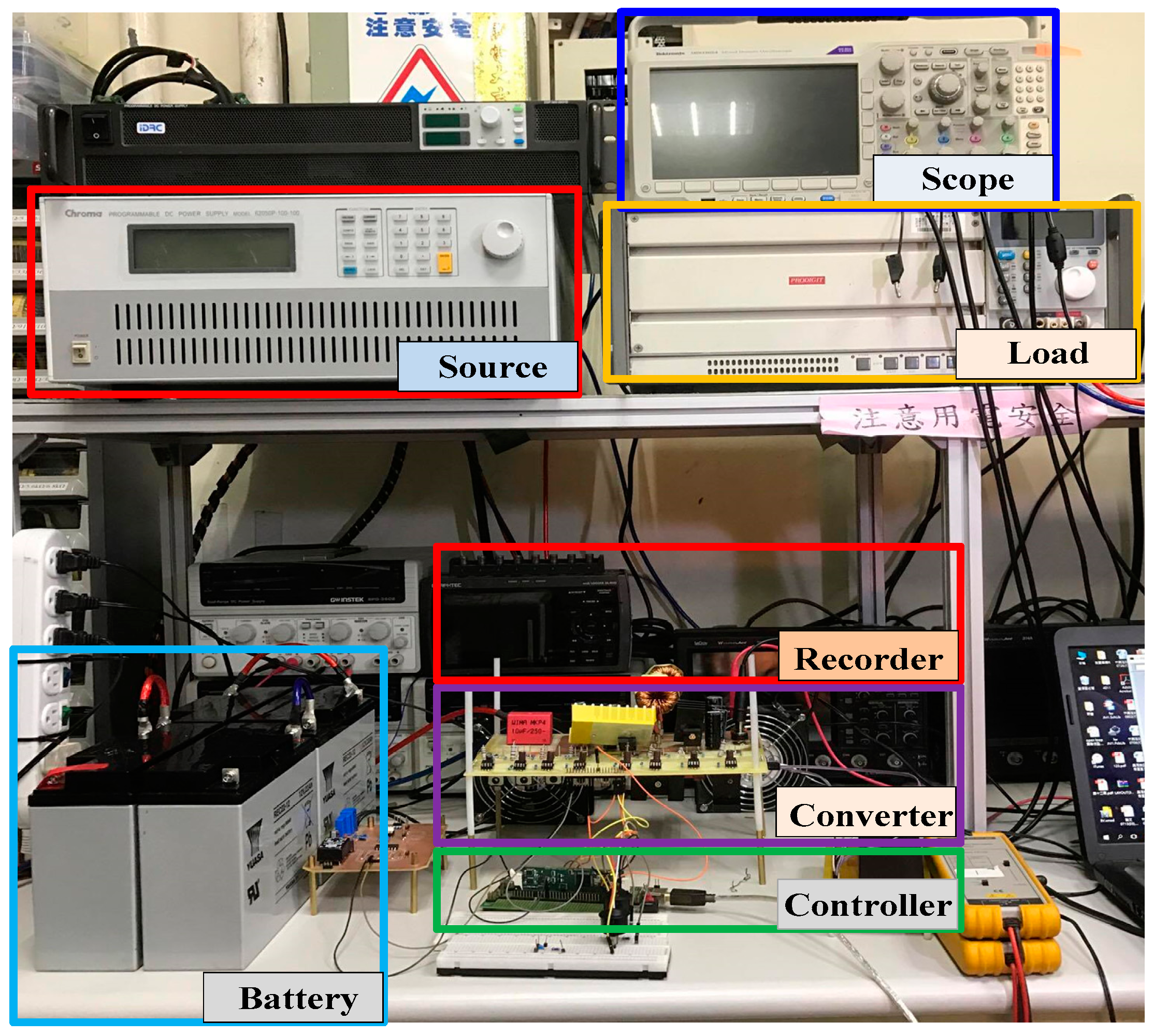
4. System Design and Implementations

Figure 6 shows the system flow chart. After starting, the system is initialized in order to determine whether the voltage on the DC-microgrid side is lower than the pre-set value. If the pre-set value is higher, the system enters the discharging state where the battery feeds the DC-microgrid. Otherwise, the system will enter the charging state where the battery voltage is compared to the 52 V. If the battery voltage is lower than 52 V, then the reflex-charging operation is executed. Then, staying in the PPP, NPP, and RP is determined using the counter time. Constant-voltage charging is executed when the battery voltage reaches 52 V.
In order to validate the proposed concept, a 500-W bidirectional DC charger system, as shown in Figure 7, is constructed as the test platform. At the low-voltage side of the platform, the voltage is set to 48 V by using four 12 V/22 Ah lead-acid batteries (REC22-12I, Taiwan Yuasa Battery Co., Ltd., Taiwan) connected in series. Lead-acid batteries were chosen due to its low cost and wide usage. For example, valve-regulated lead-acid batteries (VRLAs), such as absorbent glass mat (AGM) batteries and gel batteries, are widely used in micro hybrid electric [22,23,24].
At the high-voltage side, power supply and electronic loads are connected in parallel to simulate the actual voltage bus and its corresponding electrical units in a DC-microgrid. The parameters of the constructed converter are given in Table 1. All of the battery charging/discharging tests were recorded using the GL900 recorder (Graphtec Corporation, Tokyo, Japan).

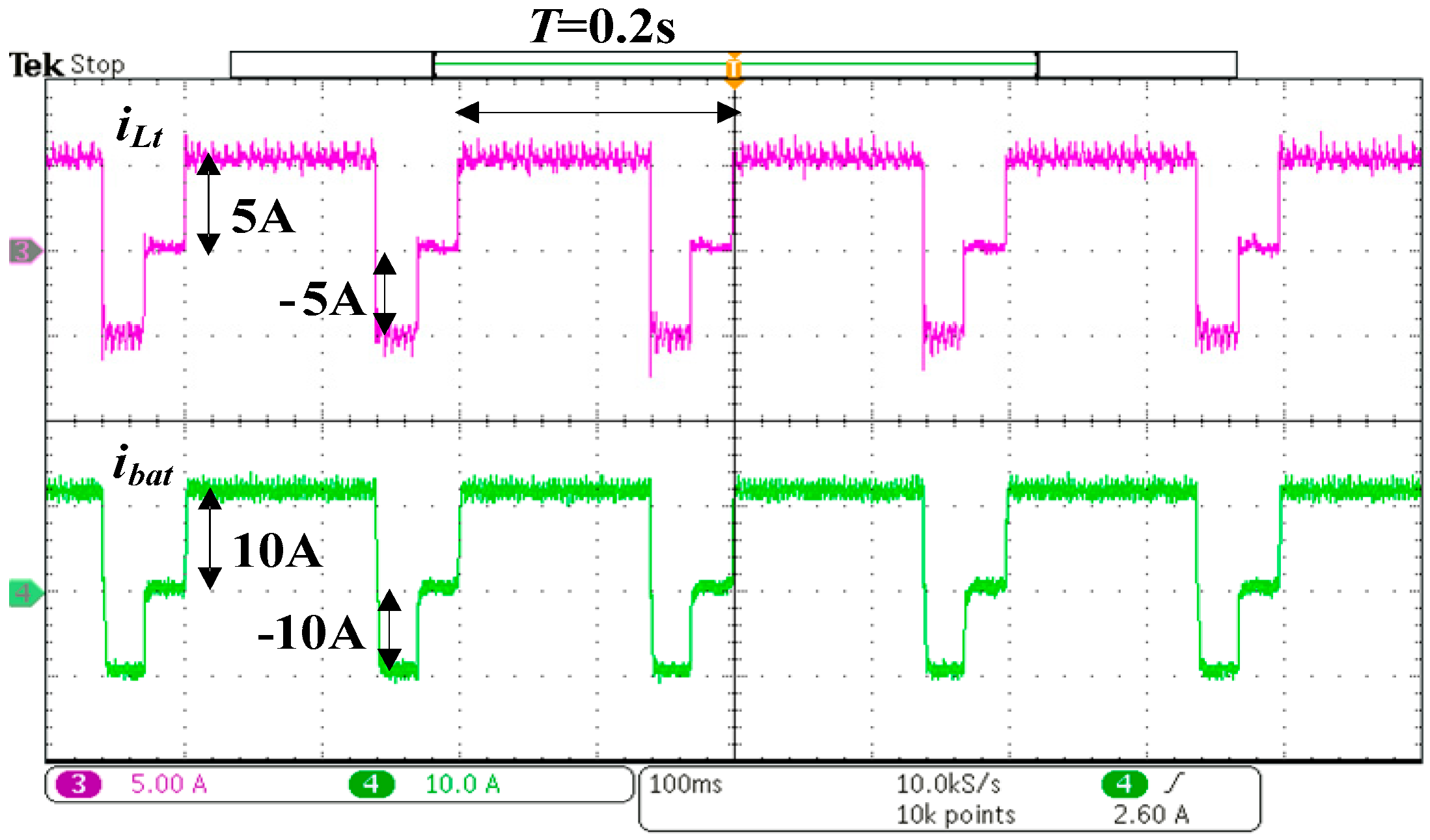
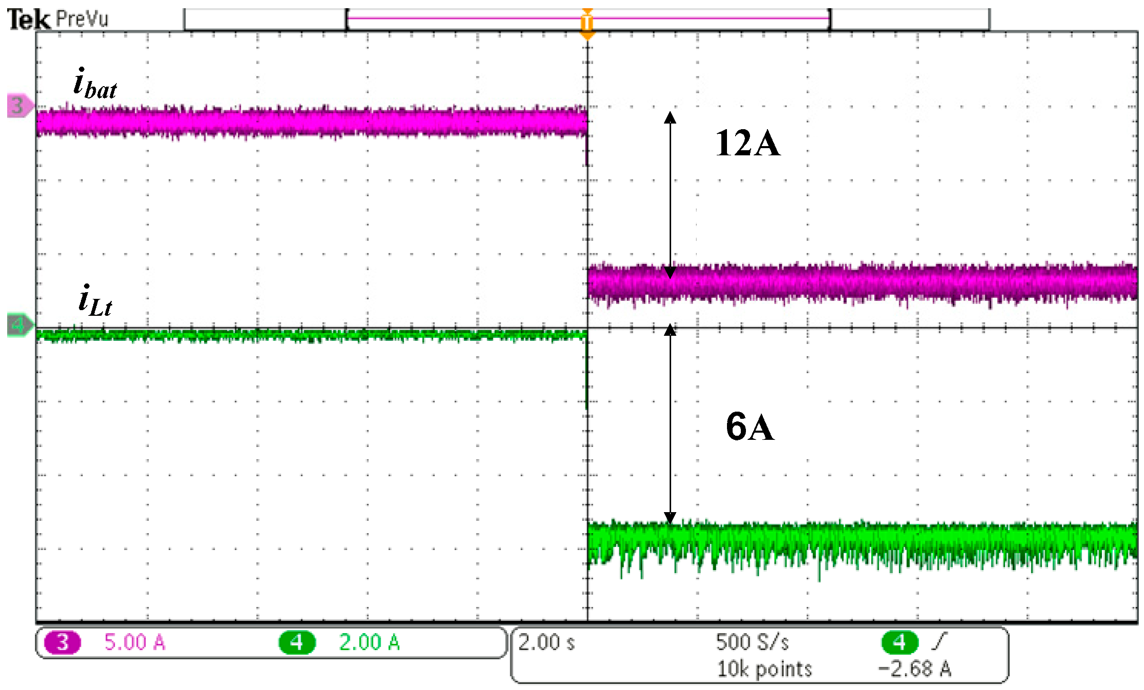
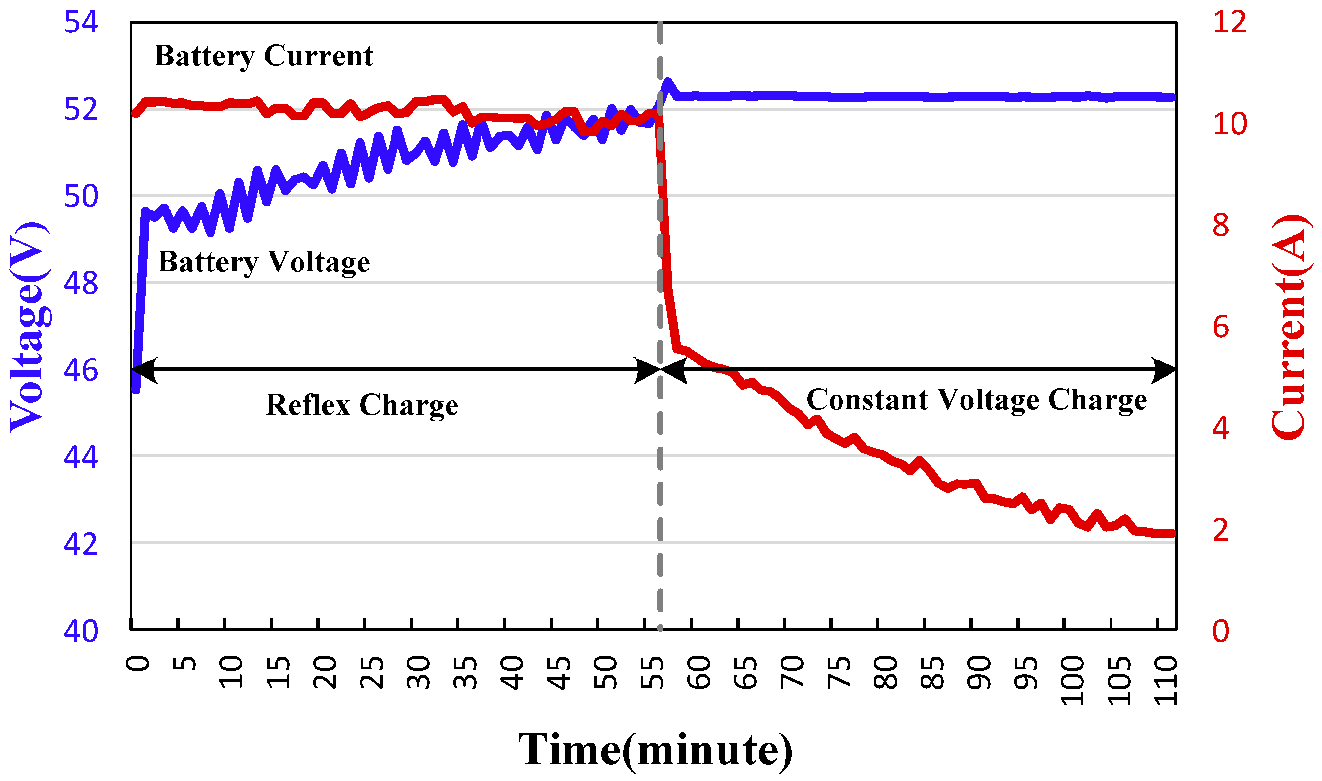
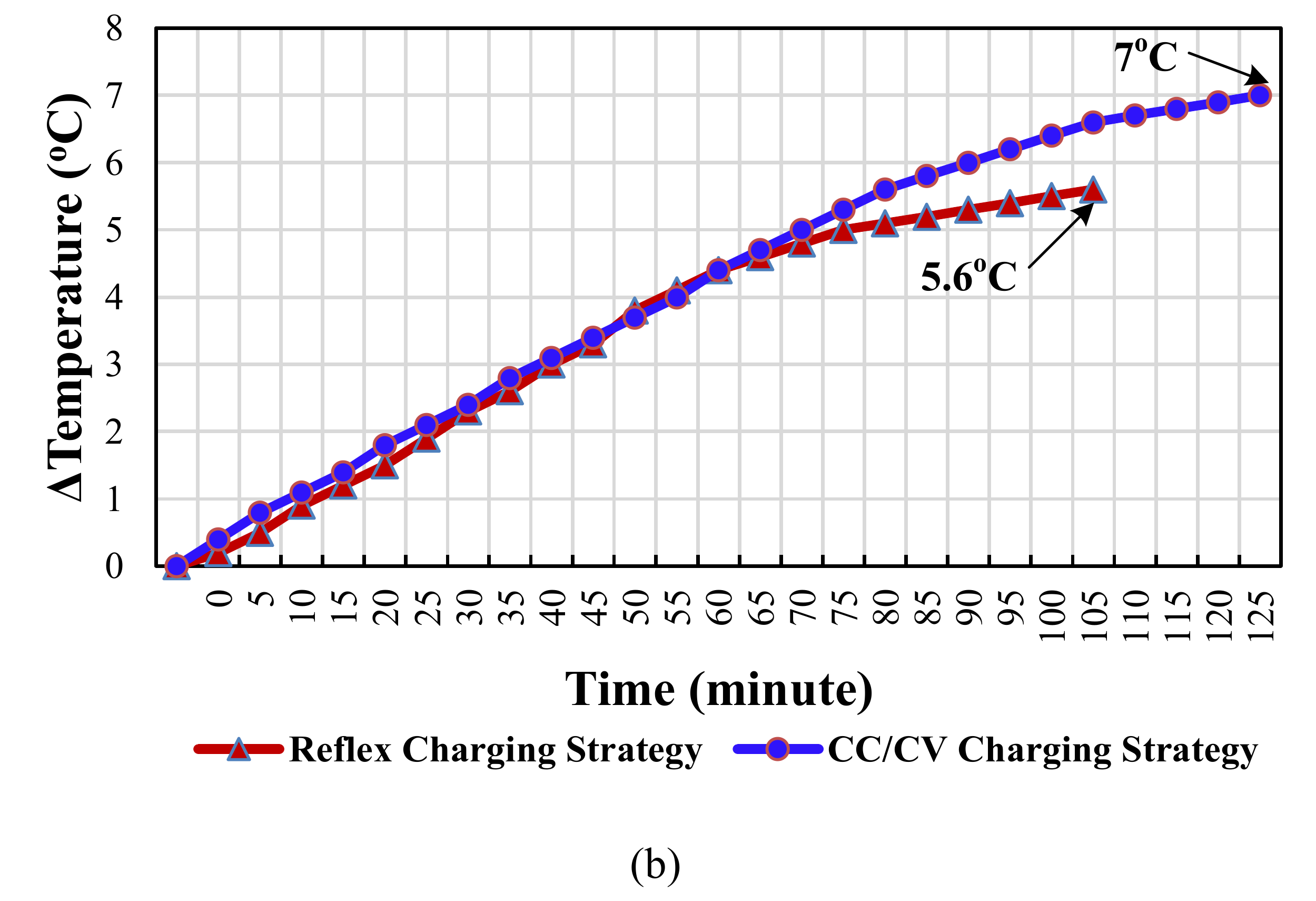
5. Experimental Results

Figure 8 illustrates the transient current control waveform of the proposed bidirectional converter. The figure shows that the battery charging current ibat rises from 5 A to 10 A and the total inductor current iLt rises from 2.5 A to 5 A (100% load). Figure 9 shows the converter waveform in the charging state. The positive charging current ibat = 10 A, whereas the negative discharging current ibat = −10 A. During PPP, the total inductor current iLt is 5 A, and it becomes −5 A during NPP. The reflex charging frequency is 5-Hz and the corresponding duty cycles for PPP and NPP are about 70% and 15%, respectively. Notably, a lot of methods [25,26,27] can be referred to adjust the reflex charging pattern (such as duty or frequency, etc.) for improving the charging efficiencies in future work.
Figure 10 shows the discharging process of the converter, it can be seen that the battery discharging current ibat is −12 A and the total inductor current iLt is −6 A. Figure 11 shows the charging curve of lead-acid batteries, which shows the reflex charging and constant-voltage charging stages. Reflex charging begins at 46 V and constant-voltage charging begins at 52 V. The charging process ends when the battery current drops to 2 A (about 0.1 C-rate). By recording the charging voltage and current of the battery every minute using the recorder, it is determined that the full charging time is 111 min.
In order to demonstrate the advantages of the proposed RC-BDC, its performance was compared with the conventional BDC with the CC/CV charging profile. Figure 12a,b show the battery charging current ibat and the increased battery temperature curves with respect to the charging time. From Figure 12a, it is clear that the charging time of the proposed RC-BDC and the typical BDC with CC/CV charging profile are about 1.85 h and 2.12 h, respectively. The charging speed of the proposed RC-BDC has been increased by about 12.7% as compared to the typical BDC. According to Figure 12b, the maximum increased in the battery temperature of the proposed RC-BDC and the typical BDC are 5.6 °C and 7 °C, respectively. The results also demonstrated that the maximum battery temperature of the proposed RC-BDC can be reduced by about 25%. This means that the thermal deterioration effect is improved by about 25% with the proposed RC-BDC.
Figure 13 shows the measured conversion efficiency of the proposed high-gain RC-BDC. The result indicates that the maximum efficiency points of charging and discharging states are 95.1% and 94.2%, respectively.

6. Conclusions

In this study, a high-gain RC-BDC for connecting LEVs to DC-microgrid is proposed. Based on the proposed controller, the high-gain bidirectional converter in [17] was able to achieve both reflex charging and energy recovery. A 500 W test platform consists of a 48-V battery connected to a 400-V DC-bus voltage was built. The experimental results verify the feasibility of the developed concept. In comparison with a typical CC/CV charging profile, the proposed high-gain RC-BDC battery charging speed and the battery thermal deterioration effect improve by about 12.7%, and 25%, respectively. In regards to the conversion efficiency, the experimental results show that the highest efficiencies that were achieved for charging and discharging states are 95.1% and 94.2%, respectively. Finally, it is worth mentioning that the proposed high-gain RC-BDC can be extended to the galvanic isolated configuration by using two high-frequency transformers as shown in Figure 14 for safety insulation requirement and higher voltage conversion ratio applications.

Acknowledgments

This research was funded by the Ministry of Science and Technology (MOST) of Republic of China under contracts 105-2221-E-027-096, 106-2218-E-027-010, 106-2622-E-027-006-CC2 and the USM Short Term Grant: 304.PELECT.60313051 and USM Bridging Grant 304.PELECT.6316117. The author would like to thank the student, Jie-Ting Li for for his help in the experiments and Yuan-Chih Lin for his suggestions.

Author Contributions

Ching-Ming Lai substantially contributed to the system design, the development of the control strategy, production and analysis of the results, and preparation of the manuscript for this study. Yun-Hsiu Li and Yu-Huei Cheng substantially contributed to the examination and interpretation of the results. Jiashen Teh substantially contributed to the review and proofreading of the manuscript.

Conflicts of Interest

The authors declare no conflict of interest.

References

  1. Hatziargyriou, N.; Asano, H.; Iravani, R.; Marnay, C. Microgrids. IEEE Power Energy Mag. 2007, 5, 78–94. [Google Scholar] [CrossRef]
  2. Pan, C.T.; Lai, C.M.; Cheng, M.C.; Hsu, L.T. A Low Switch Voltage Stress Interleaved Boost Converter for Power Factor Correction. In Proceedings of the IEEE International Conference on Power Electronics and Drive Systems Conference, Taipei, Taiwan, 2–5 November 2009; pp. 49–54. [Google Scholar]
  3. Lai, C.M.; Pan, C.T.; Cheng, M.C. High-efficiency modular high step-up interleaved boost converter for dc-microgrid applications. IEEE Trans. Ind. Appl. 2012, 48, 161–171. [Google Scholar] [CrossRef]
  4. Chukwu, U.C.; Mahajan, S.M. Real-time management of power systems with V2G facility for smart-grid applications. IEEE Trans. Sustain. Energy 2014, 5, 558–566. [Google Scholar] [CrossRef]
  5. Yilmaz, M.; Krein, P.T. Review of the impact of vehicle-to-grid technologies on distribution systems and utility interfaces. IEEE Trans. Power Electron. 2013, 28, 5673–5689. [Google Scholar] [CrossRef]
  6. Carrasco, J.M.; Franquelo, L.G.; Bialasiewicz, J.T.; Galván, E.; Guisado, R.C.P.; Prats, M.Á.M.; Leon, J.I.; Moreno-Alfonso, N. Power-electronic systems for the grid integration of renewable energy sources: A survey. IEEE Trans. Ind. Electron. 2006, 53, 1002–1016. [Google Scholar] [CrossRef]
  7. Guerrero, J.M.; Blaabjerg, F.; Zhelev, T.; Hemmes, K.; Monmasson, E.; Jemei, S.; Comech, M.P.; Granadino, R.; Frau, J.I. Distributed generation: Toward a new energy paradigm. IEEE Ind. Electron. Mag. 2010, 4, 52–64. [Google Scholar] [CrossRef]
  8. Pan, C.T.; Lai, C.M.; Cheng, M.C. A novel integrated single-phase inverter with auxiliary step-up circuit for low-voltage alternative energy source applications. IEEE Trans. Power Electron. 2010, 25, 2234–2241. [Google Scholar] [CrossRef]
  9. Vilathgamuwa, D.M.; Gajanayake, C.J.; Loh, P.C. Modulation and control of three-phase paralleled Z-source inverters for distributed generation applications. IEEE Trans. Energy Convers. 2009, 24, 173–183. [Google Scholar] [CrossRef]
  10. Lee, J.Y.; Yoon, Y.D.; Kang, J.W. A single-phase battery charger design for LEV based on DC-SRC with resonant valley-fill circuit. IEEE Trans Ind. Electron. 2015, 62, 2195–2205. [Google Scholar] [CrossRef]
  11. Lai, C.M.; Lin, Y.C.; Lee, D.S. Study and implementation of a two-phase interleaved bidirectional DC/DC converter for vehicle and dc-microgrid systems. Energies 2015, 8, 9969–9991. [Google Scholar] [CrossRef]
  12. Hu, K.W.; Liaw, C.M. Incorporated operation control of DC microgrid and electric vehicle. IEEE Trans. Ind. Electron. 2016, 63, 202–215. [Google Scholar] [CrossRef]
  13. Lin, F.J.; Hung, Y.C.; Hwang, J.C.; Chang, I.P.; Tsai, M.T. Digital signal processor-based probabilistic fuzzy neural network control of in-wheel motor drive for light electric vehicle. IET Electr. Power Appl. 2012, 6, 47–61. [Google Scholar] [CrossRef]
  14. Ke, Y.L.; Chuang, Y.C.; Kang, M.S.; Wu, Y.K.; Lai, C.M.; Yu, C.C. Solar Power Battery Charger with a Parallel-Load Resonant Converter. In Proceedings of the IEEE Industry Applications Society Annual Meeting, Orlando, FL, USA, 9–13 October 2011. [Google Scholar]
  15. Liang, T.J.; Wen, T.; Tseng, K.C.; Chen, J.F. Implementation of a regenerative pulse charger using hybrid buck-boost converter. In Proceedings of the IEEE International Conference on Power Electronics and Drive Systems, Denpasar, Indonesia, 25 October 2001; pp. 437–442. [Google Scholar]
  16. Hua, C.C.; Lin, M.Y. A study of charging control of lead-acid battery for electric vehicles. In Proceedings of the IEEE International Symposium on Industrial Electronics, Cholula, Puebla, Mexico, 4–8 December 2000. [Google Scholar]
  17. Chen, L.R.; Chu, N.Y.; Wang, C.S.; Liang, R.H. Design of a reflex-based bidirectional converter with the energy recovery function. IEEE Trans. Ind. Electron. 2008, 55, 3022–3029. [Google Scholar] [CrossRef]
  18. Wang, T.W.; Yang, M.J.; Shyu, K.K.; Lai, C.M. Design Fuzzy SOC Estimation for Sealed Lead-Acid Batteries of Electric Vehicle in ReflexTM. In Proceedings of the IEEE International Symposium on Industrial Electronics, Vigo, Spain, 4–7 June 2007; pp. 95–99. [Google Scholar]
  19. Tsai, C.T.; Kuo, Y.C.; Kuo, Y.P.; Hsieh, C.T. A Reflex Charger with ZVS and Non-Dissipative Cells for Photovoltaic Energy Conversion. Energies 2015, 8, 1373–1389. [Google Scholar] [CrossRef]
  20. Lai, C.M. Development of a novel bidirectional DC/DC converter topology with high voltage conversion ratio for electric vehicles and DC-microgrids. Energies 2016, 9, 410. [Google Scholar] [CrossRef]
  21. Lai, C.M.; Cheng, Y.H.; Li, Y.S.; Li, J.T.; Lin, Y.C. A Reflex-Charging Based Bidirectional DC Charger for Light Electric Vehicle and DC-Microgrid. In Proceedings of the IEEE Region 10 Conference, Penang, Malaysia, 5–8 November 2017; pp. 280–284. [Google Scholar]
  22. Micro Hybrid & Hybrid Vehicles Explained-Yuasa. Available online: https://www.yuasa.co.uk/info/technical/micro-hybrid-hybrid-vehicles-explained (accessed on 12 February 2018).
  23. Schaeck, S.; Stoermer, A.O.; Hockgeiger, E. Micro-hybrid electric vehicle application of valve-regulated lead-acid batteries in absorbent glass mat technology: Testing a partial-state-of-charge operation strategy. J. Power Sources 2009, 190, 173–183. [Google Scholar] [CrossRef]
  24. Valenciano, J.; Fernndez, M.; Trinidad, F.; Sanz, L. Lead-acid batteries for micro- and mild-hybrid applications. J. Power Sources 2009, 187, 599–604. [Google Scholar] [CrossRef]
  25. Chen, L.R. A design of an optimal battery pulse charge system by frequency-varied technique. IEEE Trans. Ind. Electron. 2007, 54, 398–405. [Google Scholar] [CrossRef]
  26. Chen, J.H.; Yau, H.T.; Lu, J.H. Chaos embedded particle swarm optimization algorithm-based solar optimal ReflexTM frequency charge. J. Appl. Res. Technol. 2015, 13, 321–327. [Google Scholar] [CrossRef]
  27. Wang, Z.; Wang, Y.; Rong, Y.; Li, Z.; Fantao, L. Study on the Optimal Charring Method for Lithium-ion Batteries Used in Electric Vehicles. Energy Procedia 2016, 88, 1013–1017. [Google Scholar] [CrossRef]
Figure 1. The proposed high-gain reflex-charging-based bidirectional DC charger (RC-BDC): (a) circuit topology [20], (b) battery current waveforms in charging and discharging states.
Energies 11 00623 g001
Figure 2. Schematic waveforms of the proposed high-gain RC-BDC at charging state.
Energies 11 00623 g002
Figure 3. The developed control system for the high-gain RC-BDC.
Energies 11 00623 g003
Figure 4. Block diagram for the closed-loop control scheme.
Energies 11 00623 g004
Figure 5. Frequency responses of the loop gain: (a) compensated current loop and (b) compensated voltage loop.
Energies 11 00623 g005
Figure 6. System operating flow chart.
Energies 11 00623 g006
Figure 7. Test platform for the proposed high-gain RC-BDC.
Energies 11 00623 g007
Figure 8. Transient current control waveform of the proposed high-gain RC-BDC.
Energies 11 00623 g008
Figure 9. Measured reflex charging waveform of the proposed high-gain RC-BDC.
Energies 11 00623 g009
Figure 10. Measured discharging waveform of the proposed high-gain RC-BDC.
Energies 11 00623 g010
Figure 11. The complete voltage/current charging profile of the proposed high-gain RC-BDC.
Energies 11 00623 g011
Figure 12. The comparison between the proposed RC-BDC and the conventional BDC with the CC/CV charging profile: (a) the battery charging current and (b) the increased battery temperature.
Energies 11 00623 g012aEnergies 11 00623 g012b
Figure 13. Conversion efficiency curves of the developed system for nominal voltage Vbat = 48 V and DC-bus voltage Vbus = 400 V under different loads.
Energies 11 00623 g013
Figure 14. The extended galvanic isolated configuration based on the proposed high-gain RC-BDC for safety insulation requirement and higher voltage conversion ratio applications.
Energies 11 00623 g014
Table 1. Specifications and parameters of the realized prototype.
Specifications
VH (DC-bus Voltage)380–410 V
VL (Battery Voltage)44–56 V Nominal: 48 V (four 12 V cells in series)
Power ratingPo: 500-W
Switching frequencyfs: 20 kHz
Parameters
CapacitorsCH = CL = 400 μF, CM1 = CM2 = 100 μF,
CB = 10 = 0 μF;
InductorsL1 = L2 = Ls = 800 μH;
La = Lb = 1.5 μH
MOSFETS1S4: IXFH160N15T2,
Q1Q4: W25NM60

