A Steady-State Analysis Method for Modular Multilevel Converters Connected to Permanent Magnet Synchronous Generator-Based Wind Energy Conversion Systems
Abstract
1. Introduction
- The analysis method is built on the proposed d-q frame mathematical model of MMC connected to a PMSG. Interactions of electrical quantities between the MMC and PMSG are comprehensively considered. In the d-q frame mathematical model, the time-varying quantities are transformed into constant quantities, which therefore simplifies the derivation. Due to this, the equivalent resistances in the MMC arms can be considered, and the algebraic solution of non-linear equations can be obtained to calculate the unknowns in the average switching functions.
- Only the wind speed (operating condition) is required as input, and all the electrical quantities in MMC, including the amplitudes, phase angles and their harmonics, can be calculated step by step, when the parameters, such as the capacitance and inductance in the MMC and the flux linkage in the PMSG, are set down.
- In order to improve the accuracy of the analysis, a new way to calculate the average switching functions in the mathematic model are adopted. In addition, the calculation results are obtainable at one stroke and no need for iteration. Therefore, the accuracy of analysis can be improved without sacrificing a lot calculation speed.
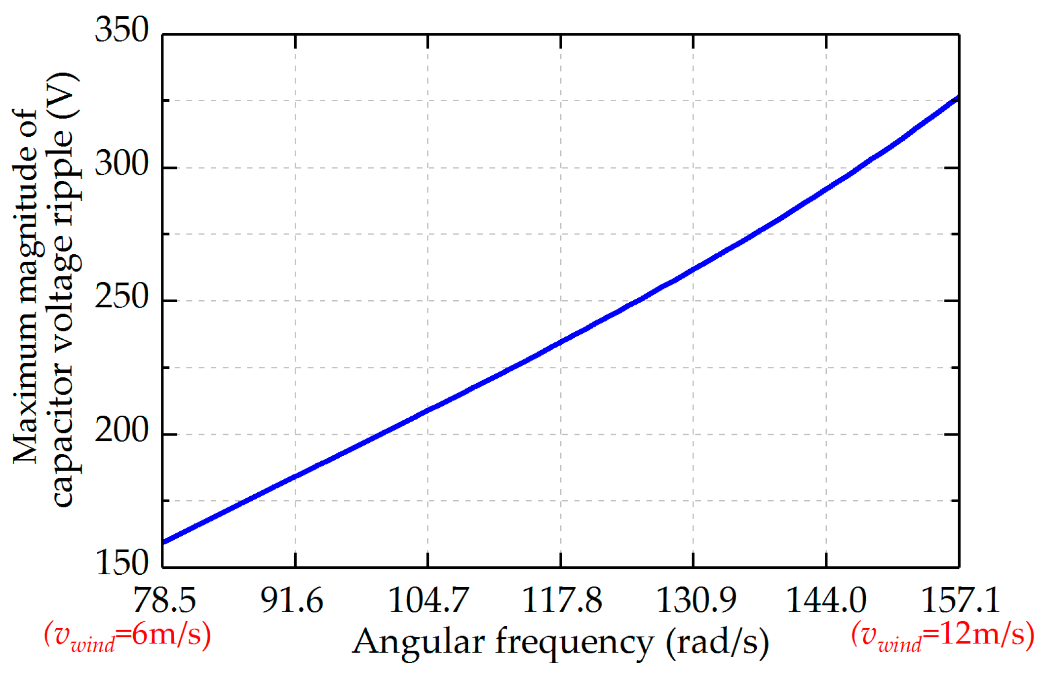
- Capacitor voltage ripple is one of the key problems in the MMC connected to variable-speed machines; this problem is further analyzed based on the proposed analysis method. The analysis results show that the MMC connected to PMSG has different characteristics from the MMC used for motor drives. A capacitor sizing method for MMC connected to PMSG is also proposed in this paper.
2. Modelling of MMC Connected to the PMSG-Based WECS
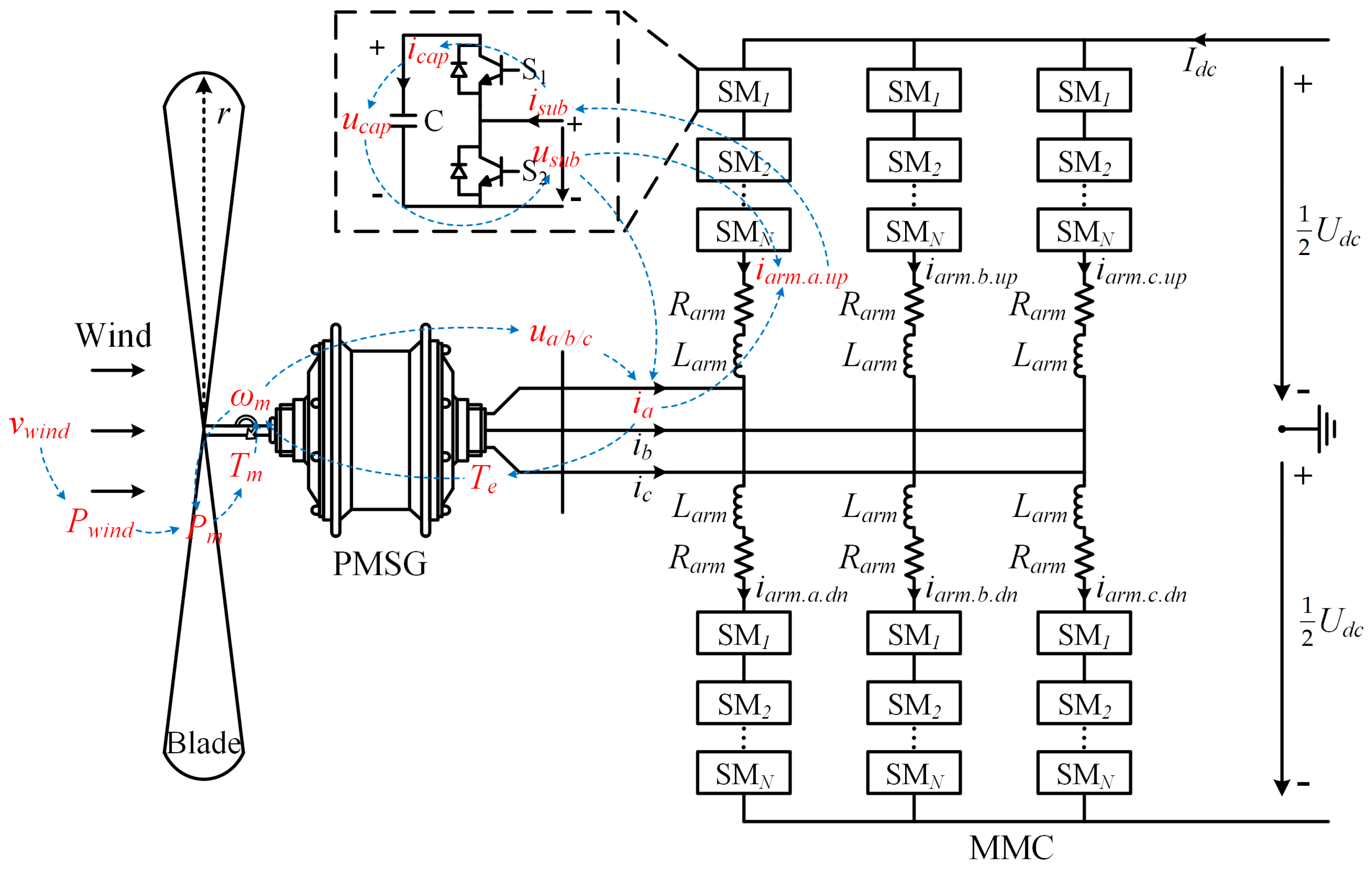
2.1. MMC Connected to the PMSG-Based WECS
2.2. Basic Configuration of MMC
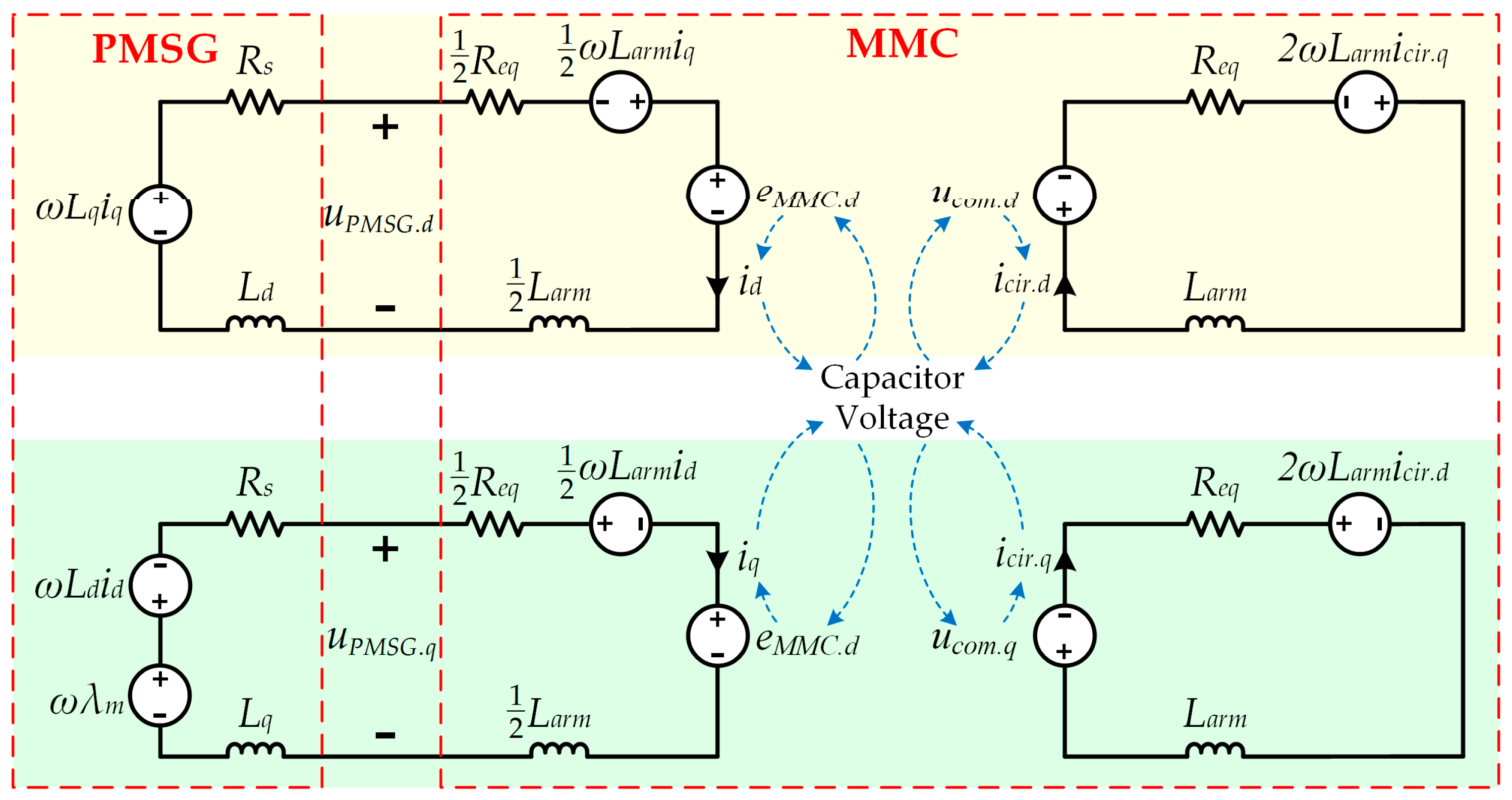
2.3. Modelling of MMC Connected to the PMSG-Based WECS
- Modelling MMC in the d-q frame facilitates the establishment of associations between the electrical quantities in PMSG and the electrical quantities in MMC, because the mathematical model of PMSG is built in the d-q frame, and the d-axis and q-axis synchronous inductances are not equal for the salient-pole PMSG.
- In the d-q frame mathematical model, the time-varying quantities are transformed into constant quantities, which therefore can simplify the derivation. Due to this, the equivalent resistances in the MMC arms can be considered in the analysis, and the algebraic solution of non-linear equations can be obtained to calculate the amplitudes and phase angles of average switching functions.
3. Calculation of the Electrical Quantities in MMC
3.1. A More Accurate Method to Calculate the Average Switching Function
- (a)
- Most of the electrical quantities in the MMC are influenced by the average switching functions, and hence adopting the more accurate average switching functions can improve the calculation accuracy.
- (b)
- Since the calculations are carried out in Matlab software, considering the 2nd harmonic component has only an insignificant influence on the calculation speed.
3.2. Calculation of the AC-Side Phase Current
3.3. Calculation of the DC-Side Current
3.4. Calculation of the Capacitor Voltage and Current
3.5. Calculation of the Sub-Module Voltage and Arm voltage
3.6. Calculation of the EMS and Common-Mode Voltage
4. The Proposed Steady-State Analysis Method
4.1. Solution Procedure of the Unknowns in the Average Switching Functions
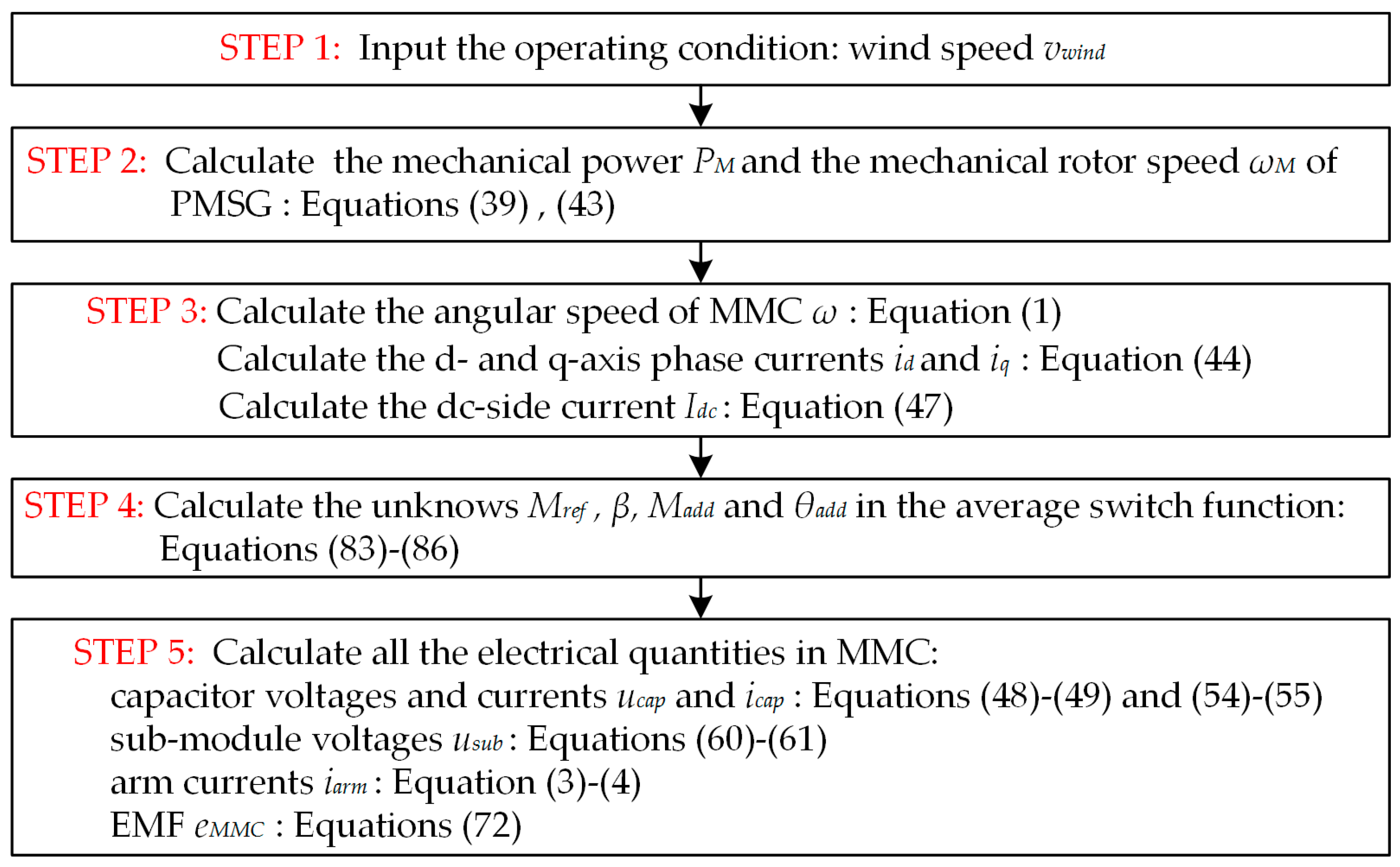
4.2. Flow Chart of the Proposed Analysis Method
- Step 1: the value of the wind speed is inputted, which decides the operating condition of WCES.
- Step 2: the mechanical power and the mechanical rotor speed of PMSG are calculated. It should be noted that the proposed method is also applicable for the condition, in which the wind turbine is not working under the MPPT control. In that condition, the first step is skipped, and the calculation procedure starts with the second step, which means the inputted operating condition is not the wind speed but the mechanical power and mechanical rotor.
- Step 3: the angular speed, phase currents and dc-side currents of MMC are calculated. The calculations of these electrical quantities are not relevant to the switching functions.
- Step 4: the unknown quantities in the average switching functions are calculated based on Equations (83)–(86).
- Step 5: all the electrical quantities of MMC, including the amplitudes, the phase angles, and their harmonics, can be obtained based on the formulas shown in this paper.
5. Application of the Proposed Analysis Method
5.1. Analysis of Capacitor Voltage Ripple in the MMC Connected to PMSG
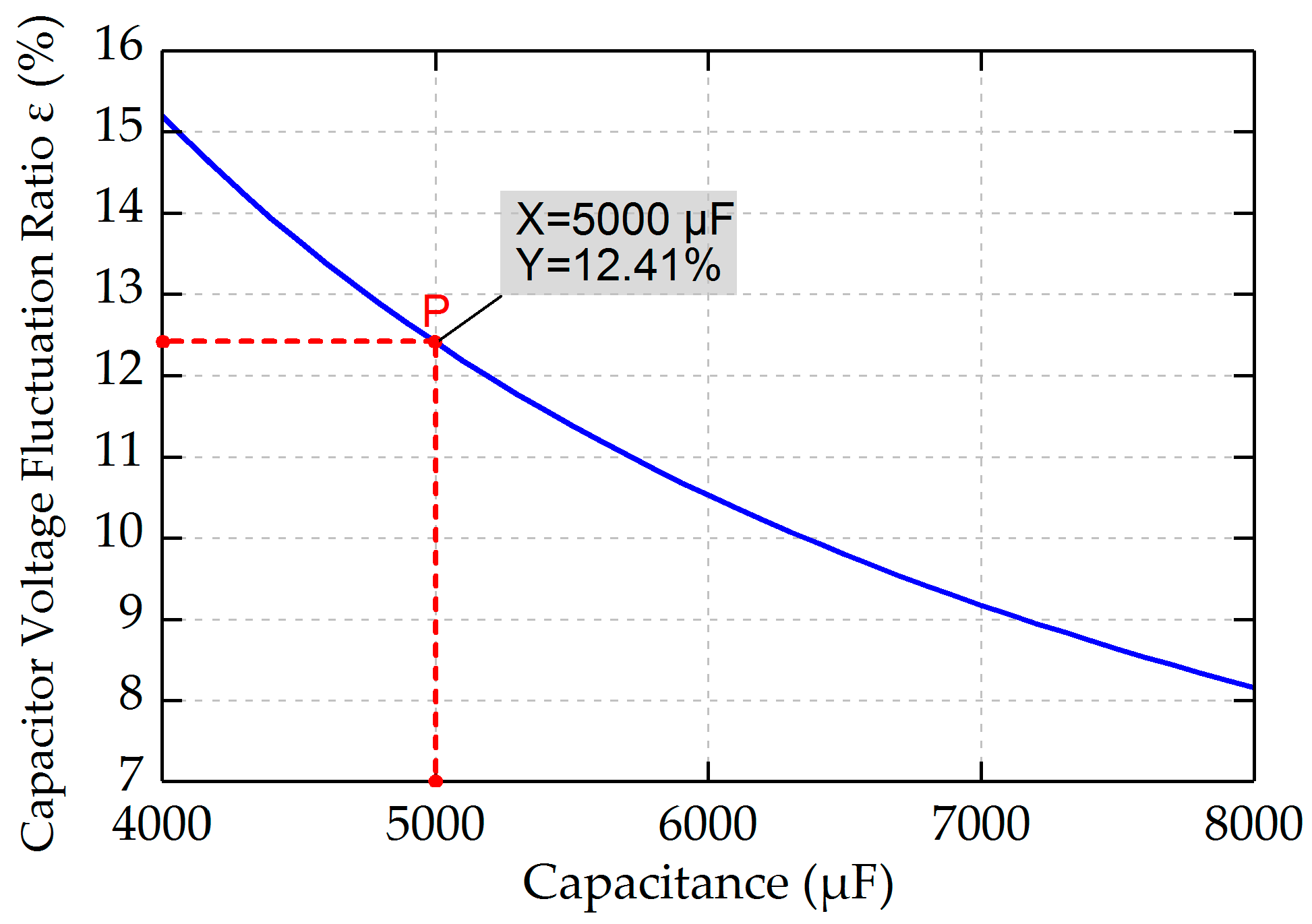
5.2. Capacitor Sizing For the MMC Connected to PMSG
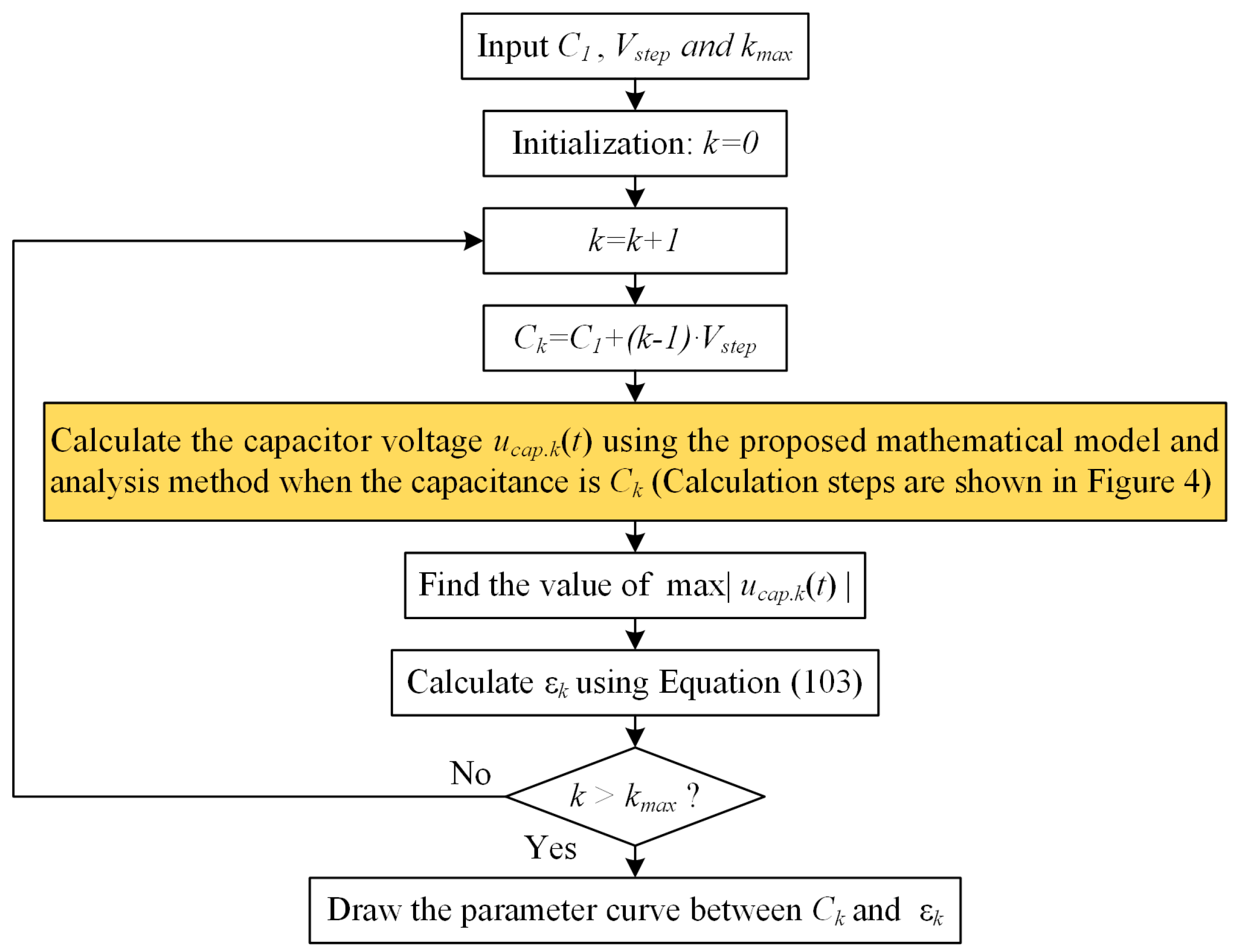
- Step 1: Draw the parameter curve based on the proposed mathematical model and analysis method shown in Section 4. The parameter curve describes the relationship between the capacitance and the capacitor voltage fluctuation ratio ε.
- Step 2: Select the appropriate value of capacitance according to the obtained parameter curve.
- (a)
- The parameter curve is drawn by using the software, such as MATLAB.
- (b)
- The calculation of the capacitor voltage is the key step, the calculation steps are elaborated in Section 4.
- (c)
- To find the value of , “max” function can be used in the program in MATLAB.
6. Simulation Results
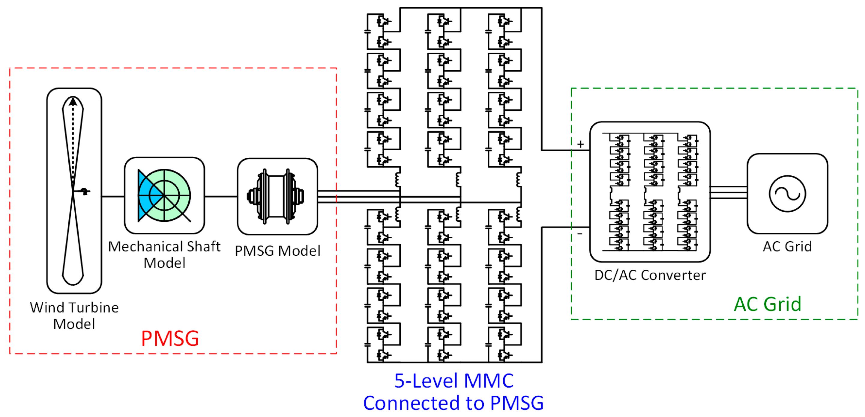
6.1. Simulation Model
- (a)
- In the PMSG part, the wind turbine model is built based on the wind power formula. The mechanical shaft model uses a two-mass rotor model, with separate masses for the turbine and generator. The PSMG model is the typical model provided by MATLAB/Simulink. More details of this part can be referred to the paper [32].
- (b)
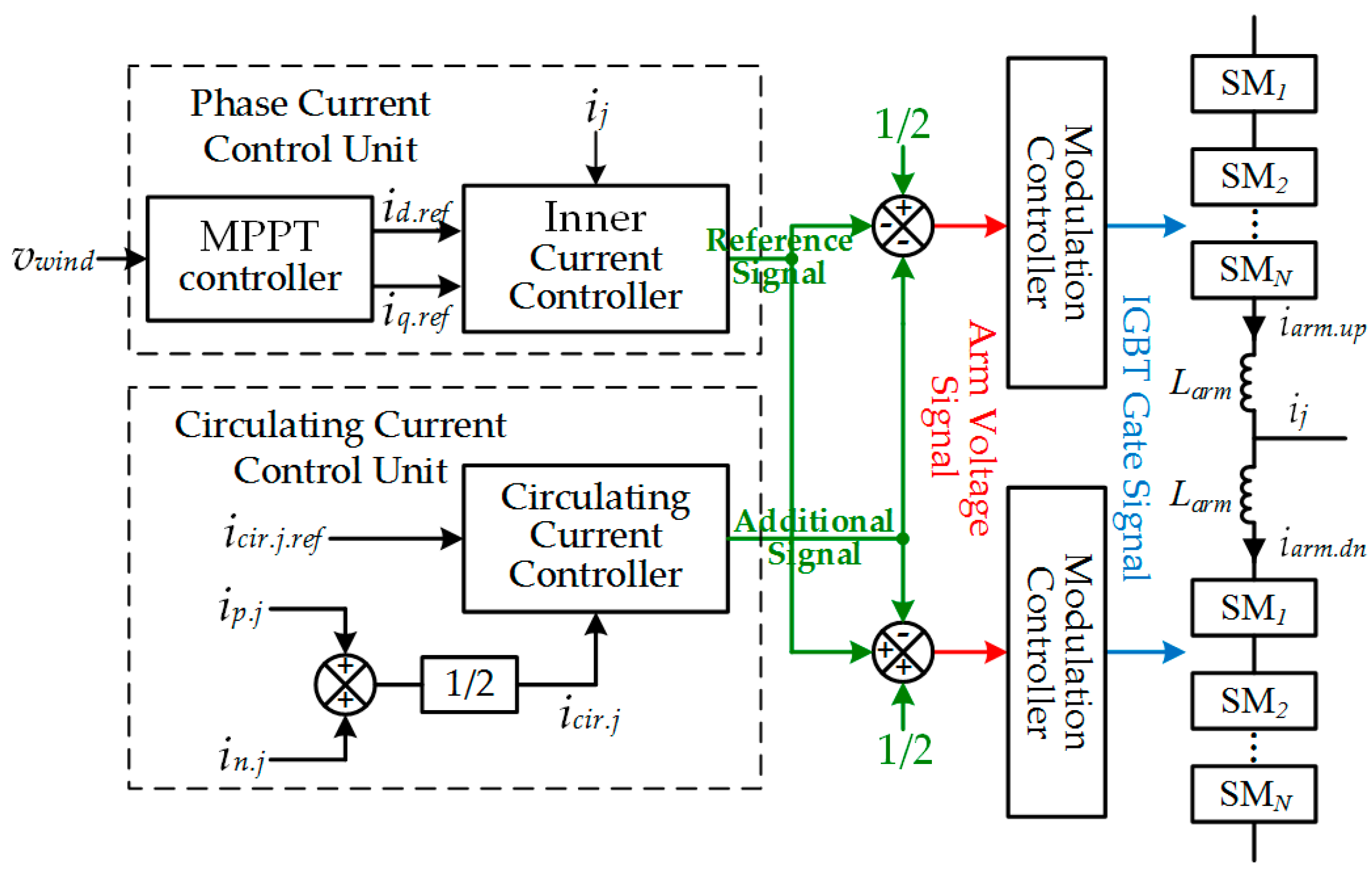
- In the MMC connected to PSMG part, a five level MMC is built. As is shown in Figure 7, the sub-modules use half-bridge topology. MPPT controller is used to make the PMSG obtain the highest possible power from wind. PI controllers are used to track the reference values in the inner current controller and the circulating current controller. The IGBT gate signals (the switching function in the mathematic model) are obtained by comparing the arm voltage signals with the carrier signals. Details of this part can be referred to the paper [12].
- (c)
- In the AC grid part, the DC/AC converter is the traditional modular multilevel converter used in HVDC [17]. The AC grid is substituted with a three-phase AC source, in which the frequency is 50 Hz.
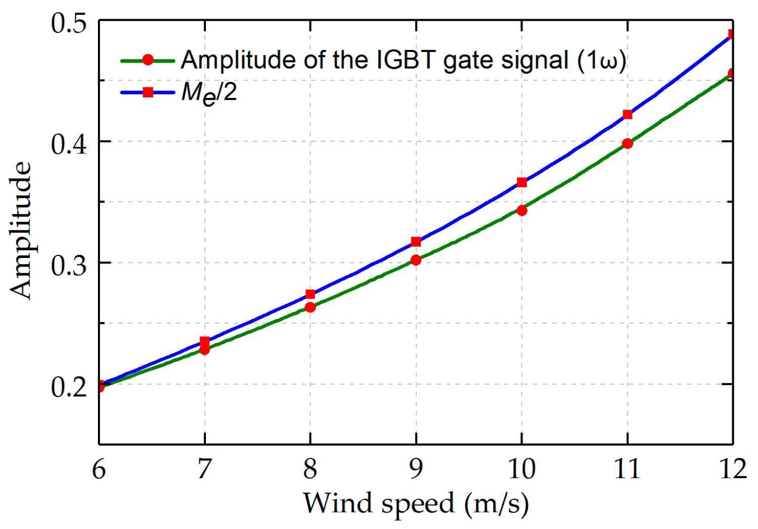
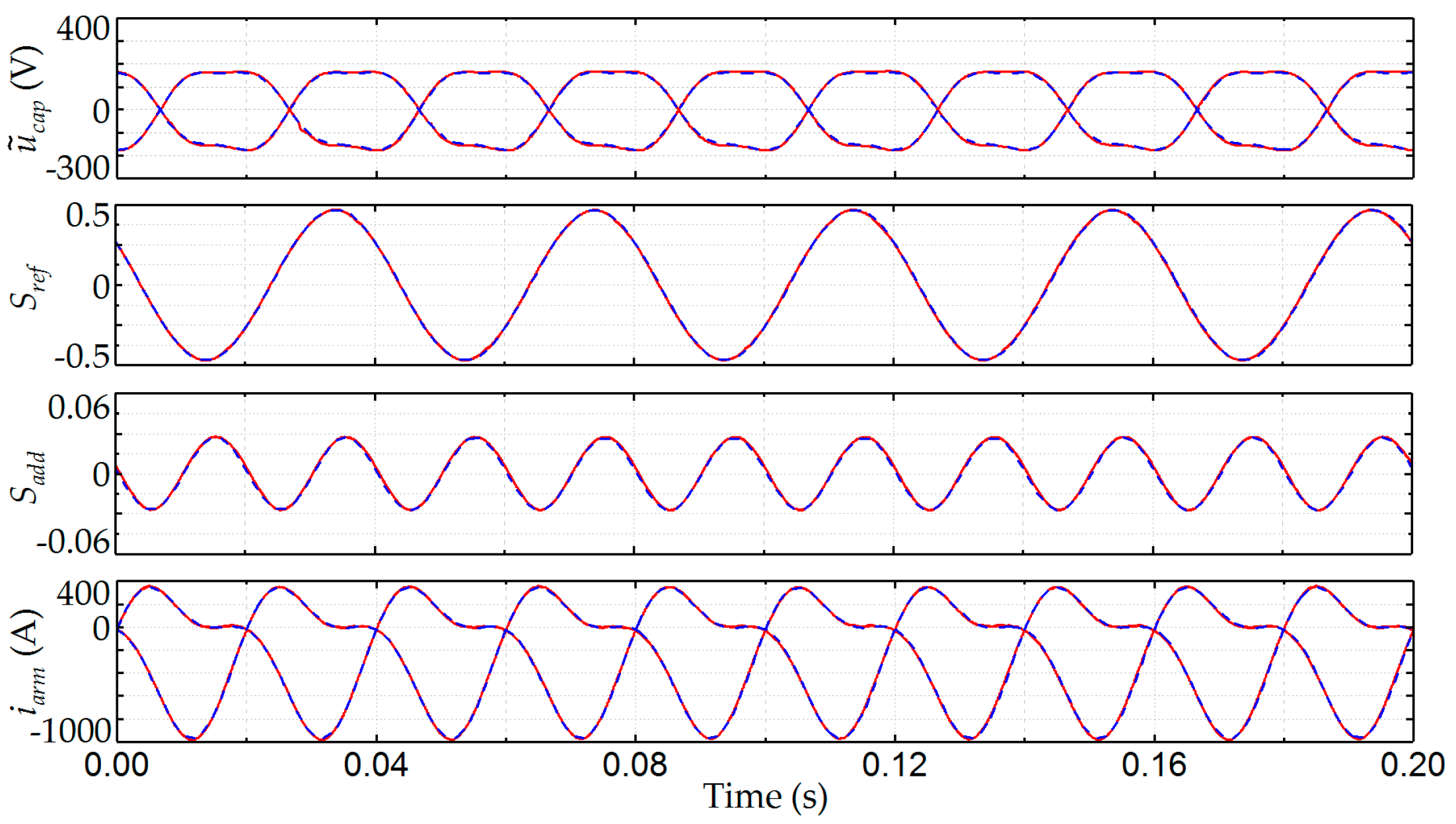
6.2. The Proposed Method to Calculate the Average Switching Functions
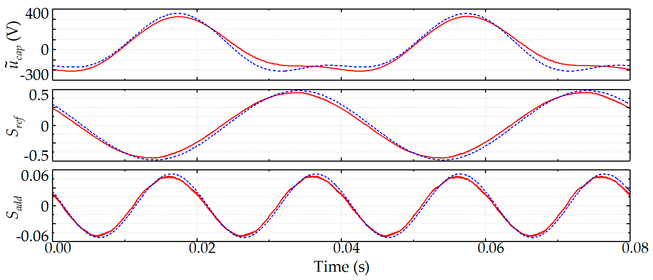
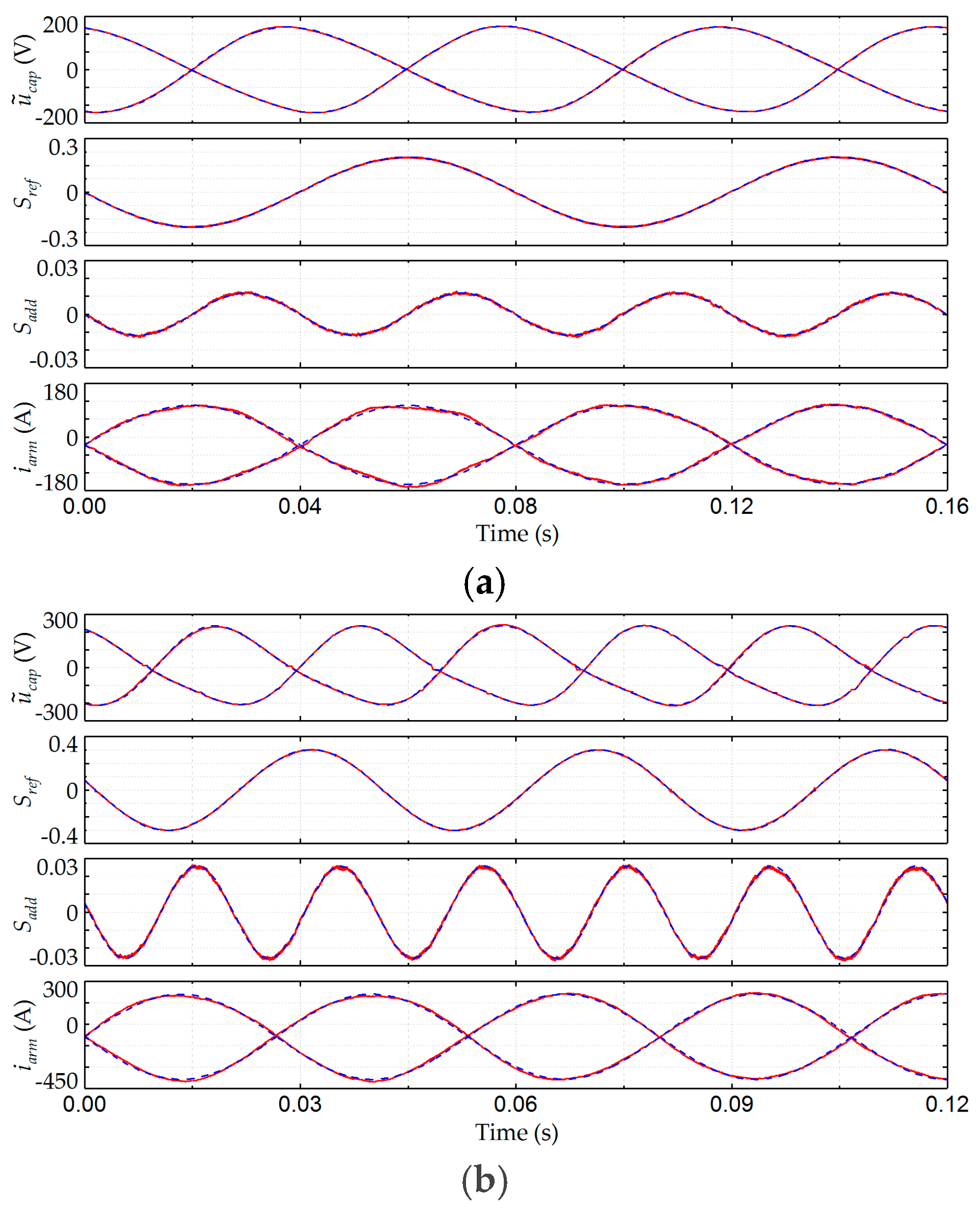
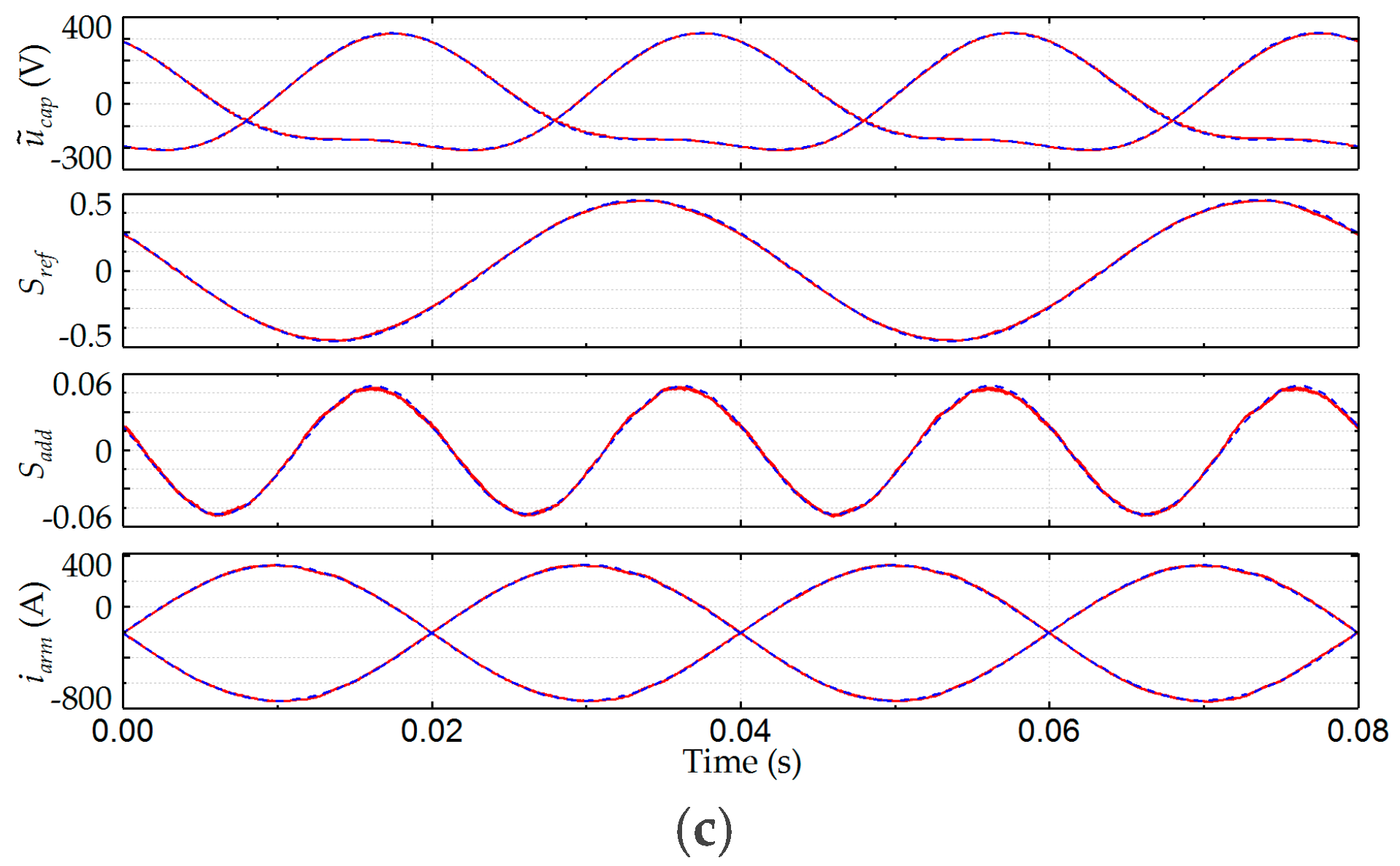
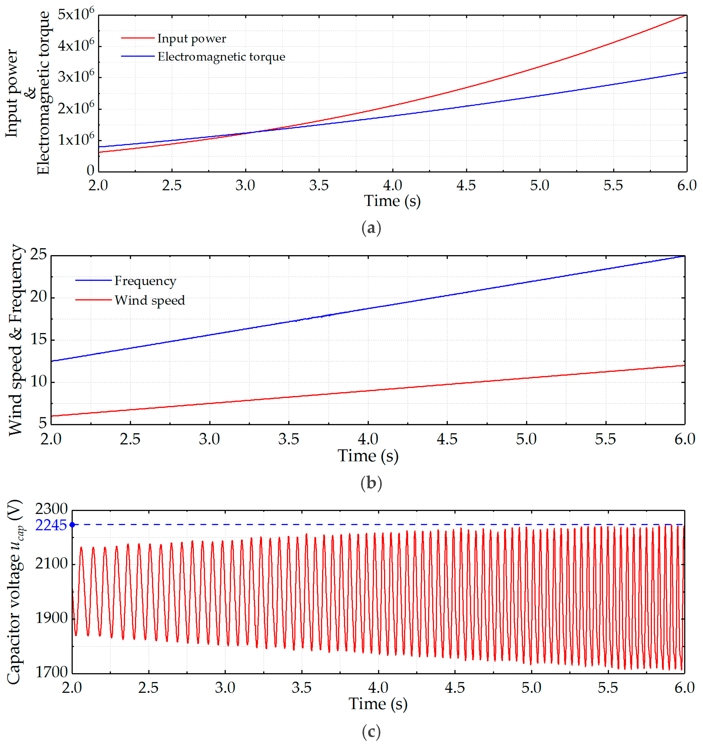
6.3. Simulation and Calculation Results for the Proposed Analysis Method
6.4. Simulation Results of the Capacitor Voltage Ripple
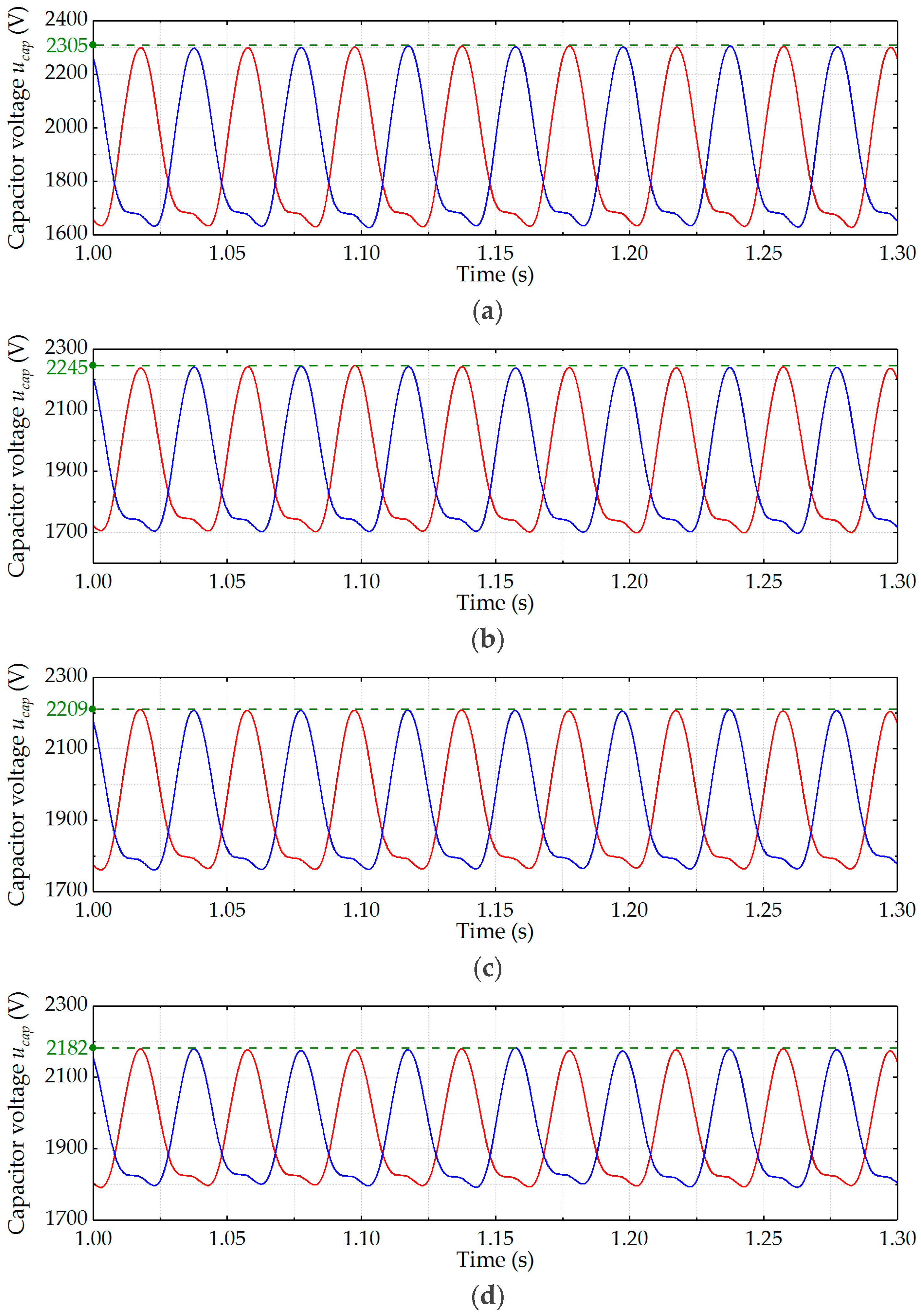
6.5. Simulation Results of the Capacitor Voltage Ripple under Different Capacitance Conditions
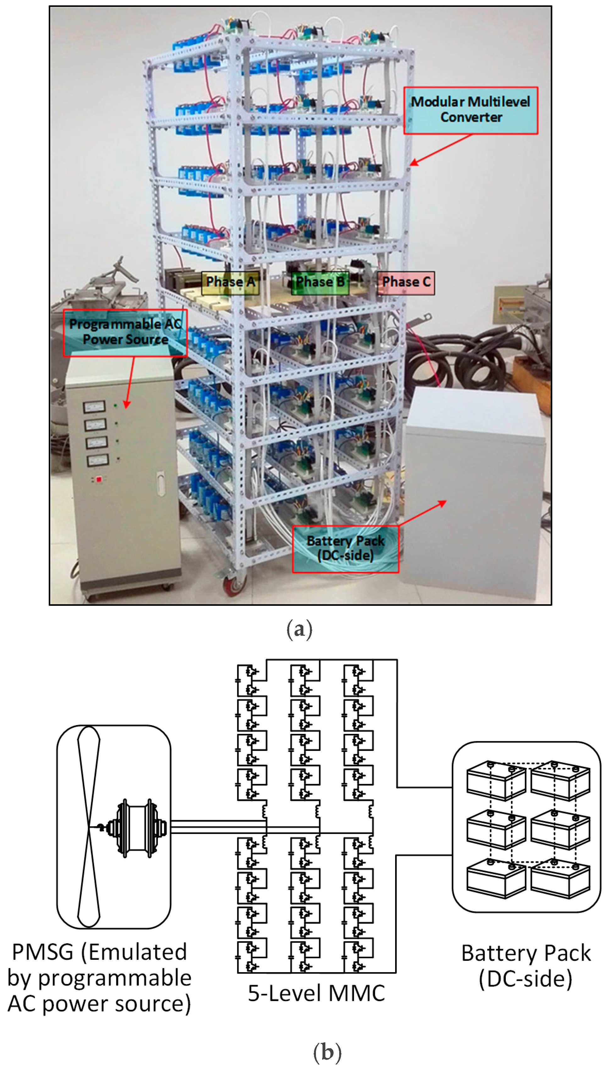
7. Experiment Validation
8. Conclusions
Acknowledgments
Author Contributions
Conflicts of Interest
References
- Chavira, F.; Ortega-Cisneros, S.; Rivera, J. A Novel Sliding Mode Control Scheme for a PMSG-Based Variable Speed Wind Energy Conversion System. Energies 2017, 10, 1476. [Google Scholar] [CrossRef]
- Yaramasu, V.; Wu, B.; Sen, P.C.; Kouro, S.; Narimani, M. High-power Wind Energy Conversion Systems: State-of-the-art and Emerging Technologies. Proc. IEEE 2015, 103, 740–788. [Google Scholar] [CrossRef]
- Zhao, L.; Adamiak, K. Numerical Simulation of the Effect of EHD Flow on Corona Discharge in Compressed Air. IEEE Trans. Ind. Appl. 2013, 49, 298–304. [Google Scholar] [CrossRef]
- Cheng, X.; Lee, W.J.; Sahni, M.; Cheng, Y.; Lee, L.K. Dynamic Equivalent Model Development to Improve the Operation Efficiency of Wind Farm. IEEE Trans. Ind. Appl. 2016, 52, 2759–2767. [Google Scholar] [CrossRef]
- Yaramasu, V.; Dekka, A.; Durán, M.J.; Kouro, S.; Wu, B. PMSG-based wind energy conversion systems: Survey on power converters and controls. IET Electr. Power Appl. 2017, 11, 956–968. [Google Scholar] [CrossRef]
- Yuan, X. A Set of Multilevel Modular Medium-Voltage High Power Converters for 10-MW Wind Turbines. IEEE Trans. Sustain. Energy 2014, 5, 524–534. [Google Scholar] [CrossRef]
- Abu-Rub, H.; Holtz, J.; Rodriguez, J.; Ge, B. Medium-Voltage Multilevel Converters-State of the Art, Challenges, and Requirements in Industrial Applications. IEEE Trans. Ind. Electron. 2010, 57, 2581–2596. [Google Scholar] [CrossRef]
- Hagiwara, M.; Nishimura, K.; Akagi, H. A Medium-Voltage Motor Drive with a Modular Multilevel PWM Inverter. IEEE Trans. Power Electron. 2010, 25, 1786–1799. [Google Scholar] [CrossRef]
- Antonopoulos, A.; Angquist, L.; Norrga, S.; Ilves, K.; Harnefors, L.; Nee, H.P. Modular Multilevel Converter AC Motor Drives with Constant Torque from Zero to Nominal Speed. IEEE Trans. Ind. Appl. 2014, 50, 1982–1993. [Google Scholar] [CrossRef]
- Iversen, T.M.; Gjerde, S.S.; Undeland, T. Multilevel converters for a 10 MW, 100 kV transformer-less offshore wind generator system. In Proceedings of the 15th European Conference on Power Electronics and Applications (EPE), Lille, France, 2–6 September 2013. [Google Scholar]
- Liu, H.; Ma, K.; Loh, P.C.; Blaabjerg, F. Online Fault Identification Based on an Adaptive Observer for Modular Multilevel Converters Applied to Wind Power Generation Systems. Energies 2015, 8, 7140–7160. [Google Scholar] [CrossRef]
- Wang, M.; Hu, Y.; Zhao, W.; Wang, Y; Chen, G. Application of modular multilevel converter in medium voltage high power permanent magnet synchronous generator wind energy conversion systems. IET Renew. Power Gener. 2016, 10, 824–833. [Google Scholar] [CrossRef]
- Holtsmark, N.; Bahirat, H.J.; Molinas, M.; Mork, B.A.; Hoidalen, H.K. An All-DC Offshore Wind Farm with Series-Connected Turbines: An Alternative to the Classical Parallel AC Model? IEEE Trans. Ind. Electron. 2013, 60, 2420–2428. [Google Scholar] [CrossRef]
- Parastar, A.; Kang, Y.C.; Seok, J.K. Multilevel Modular DC/DC Power Converter for High-Voltage DC-Connected Offshore Wind Energy Applications. IEEE Trans. Ind. Electron. 2015, 62, 2879–2890. [Google Scholar] [CrossRef]
- Liu, H.; Guo, H.; Liang, J.; Qi, L. Impedance-Based Stability Analysis of MVDC Systems Using Generator-Thyristor Units and DTC Motor Drives. IEEE J. Emerg. Sel. Top. Power Electron. 2017, 5, 5–13. [Google Scholar] [CrossRef]
- Ilves, K.; Antonopoulos, A.; Norrga, S.; Nee, H.P. Steady-State Analysis of Interaction between Harmonic Components of Arm and Line Quantities of Modular Multilevel Converters. IEEE Trans. Power Electron. 2012, 27, 57–68. [Google Scholar] [CrossRef]
- Song, Q.; Liu, W.; Li, X.; Rao, H.; Xu, S.; Li, L. A Steady-State Analysis Method for a Modular Multilevel Converter. IEEE Trans. Power Electron. 2013, 28, 3702–3713. [Google Scholar] [CrossRef]
- Vasiladiotis, M.; Cherix, N.; Rufer, A. Accurate Capacitor Voltage Ripple Estimation and Current Control Considerations for Grid-Connected Modular Multilevel Converters. IEEE Trans. Power Electron. 2014, 29, 4568–4579. [Google Scholar] [CrossRef]
- Wang, J.; Liang, J.; Gao, F.; Dong, X.; Wang, C.; Zhao, B. A Closed-Loop Time-Domain Analysis Method for Modular Multilevel Converter. IEEE Trans. Power Electron. 2017, 32, 7494–7508. [Google Scholar] [CrossRef]
- Ilves, K.; Antonopoulos, A.; Harnefors, L.; Norrga, S.; Angquist, L.; Nee, H.P. Capacitor Voltage Ripple Shaping in Modular Multilevel Converters Allowing for Operating Region Extension. In Proceedings of the IECON 2011—37th Annual Conference on IEEE Industrial Electronics Society, Melbourne, Australia, 7–10 November 2011. [Google Scholar]
- Ma, C.; Qu, L. Multiobjective Optimization of Switched Reluctance Motors Based on Design of Experiments and Particle Swarm Optimization. IEEE Trans. Energy Convers. 2015, 30, 1144–1153. [Google Scholar] [CrossRef]
- Kunjumuhammed, L.P.; Pal, B.C.; Gupta, R.; Dyke, K.J. Stability Analysis of a PMSG-Based Large Offshore Wind Farm Connected to a VSC-HVDC. IEEE Trans. Energy Convers. 2017, 32, 1166–1176. [Google Scholar] [CrossRef]
- Yazdani, A.; Iravani, R. A Neutral-Point Clamped Converter System for Direct-Drive Variable-Speed Wind Power Unit. IEEE Trans. Energy Convers. 2006, 21, 596–607. [Google Scholar] [CrossRef]
- Debnath, S.; Saeedifard, M. A New Hybrid Modular Multilevel Converter for Grid Connection of Large Wind Turbines. IEEE Trans. Sustain. Energy 2013, 4, 1051–1064. [Google Scholar] [CrossRef]
- Jung, J.J.; Lee, H.J.; Sul, S.K. Control Strategy for Improved Dynamic Performance of Variable-Speed Drives with Modular Multilevel Converter. IEEE J. Emerg. Sel. Top. Power Electron. 2015, 3, 371–380. [Google Scholar] [CrossRef]
- Yu, L.; Li, R.; Xu, L. Distributed PLL-based Control of Offshore Wind Turbine Connected with Diode-Rectifier based HVDC Systems. IEEE Trans. Power Deliv. 2017. [Google Scholar] [CrossRef]
- He, L.; Zhang, K.; Xiong, J.; Fan, S.; Xue, Y. Low-Frequency Ripple Suppression for Medium-Voltage Drives Using Modular Multilevel Converter with Full-Bridge Submodules. IEEE J. Emerg. Sel. Top. Power Electron. 2016, 4, 657–667. [Google Scholar] [CrossRef]
- Merlin, M.M.; Green, T.C. Cell Capacitor Sizing in Multilevel Converters: Cases of the Modular Multilevel Converter and Alternate Arm Converter. IET Power Electron. 2015, 8, 350–360. [Google Scholar] [CrossRef]
- Xu, Z.; Xiao, H.; Zhang, Z. Selection Methods of Main Circuit Parameters for Modular Multilevel Converters. IET Renew. Power Gener. 2016, 10, 788–797. [Google Scholar] [CrossRef]
- Li, R.; Fletcher, J.E. A Hybrid Modular Multilevel Converter with Novel Three-Level Cells for DC Fault Blocking Capability. IEEE Trans. Power Deliv. 2015, 30, 2017–2026. [Google Scholar] [CrossRef]
- Li, R.; Fletcher, J.E.; Xu, L.; Williams, B.W. Enhanced Flat-Topped Modulation for MMC Control in HVDC Transmission Systems. IEEE Trans. Power Deliv. 2017, 32, 152–161. [Google Scholar] [CrossRef]
- Miller, N.W.; Sanchez-Gasca, J.J.; Price, W.W.; Delmerico, R.W. Dynamic modeling of GE 1.5 and 3.6 MW wind turbine-generators for stability simulations. In Proceedings of the 2003 IEEE Power Engineering Society General Meeting, Toronto, ON, Canada, 13–17 July 2003. [Google Scholar]
- Diaz, M.; Cardenas, R.; Espinoza, M.; Rojas, F.; Mora, A.; Clare, J.C.; Wheeler, P. Control of Wind Energy Conversion Systems Based on the Modular Multilevel Matrix Converter. IEEE Trans. Ind. Electron. 2017, 64, 8799–8810. [Google Scholar] [CrossRef]


| Parameter | Simulation | Experiment |
|---|---|---|
| Rated power | 5 MVA | 6 kVA |
| Rated system frequency | 25 Hz | 40 Hz |
| Rated line voltage | 4000 V | 200 V |
| DC-link voltage | ±4000 V | ±200 V |
| Number of SMs per arm | 4 | 4 |
| SM capacitor | 5000 μF | 1500 μF |
| Arm inductrance | 3 mH | 1.5 mH |
| Equaivalent resistance | 0.2 Ω | 0.48 Ω |
| Carrier frequency | 2500 Hz | 4000 Hz |
| Parameter | Simulation | Experiment |
|---|---|---|
| Rated power | 5 MVA | 6 kVA |
| Rated wind speed | 12 m/s | 12 m/s |
| D-axis inductance | 5.3 mH | 5.4 mH |
| Q-axis inductance | 12.5 mH | 5.4 mH |
| Maximum flux | 20 Wb | 0.68 Wb |
| Number of pole-pairs | 100 | 4 |
| Wind Speed (m/s) | IGBT Gate Signal (1ω) | Proposed Method (1ω) | Traditional Method (1ω) | |||
|---|---|---|---|---|---|---|
| Ampl. | Ang. (°) | Ampl. | Ang. (°) | Ampl. | Ang. (°) | |
| 6 | 0.197 | −89.6 | 0.198 | −90.1 | 0.199 | −100.7 |
| 8 | 0.263 | −98.2 | 0.263 | −98.6 | 0.274 | −108.6 |
| 10 | 0.343 | −109.2 | 0.342 | −109.4 | 0.366 | −117.8 |
| 12 | 0.456 | −121.4 | 0.457 | −121.5 | 0.488 | −127.1 |
| Item | Simulation Results/Calculation Results/Errors | ||||
|---|---|---|---|---|---|
| Amplitude | Phase Angle (°) | ||||
| (V) | 1ω | 3912.4/3884.2 | 0.72% | 52.8/53.1 | 0.57% |
| (A) | 1ω | 1061.7/1061.1 | 0.06% | 90/90 | 0% |
| (A) | dc | −618.9/−617.8 | 0.18% | N/A | N/A |
| (A) | 1ω | 200.24/199.87 | 0.18% | −72.2/−71.7 | 0.69% |
| 2ω | 124.74/124.65 | 0.07% | 142.9/143.3 | 0.28% | |
| 3ω | 13.15/13.37 | 1.67% | 161.1/157.8 | 2.05% | |
| (V) | ω | 253.85/254.32 | 0.19% | −162.2/−161.6 | 0.37% |
| 2ω | 77.83/79.31 | 1.90% | 54.1/53.4 | 1.29% | |
| 3ω | 5.78/5.69 | 1.90% | 72.8/71.5 | 1.79% | |
| (A) | dc | −206.21/−205.93 | 0.14% | N/A | N/A |
| ω | 530.84/530.5 | 0.06% | −90/−90 | 0% | |
| ω | 0.457/0.461 | 0.88% | 58.5/58.0 | 0.85% | |
| 2ω | 0.049/0.050 | 2.04% | 68.2/67.7 | 0.73% | |
| Item | Calculation Time (s) | |||
|---|---|---|---|---|
| 100 Times | 1000 Times | 5000 Times | 10000 Times | |
| Traditional | 0.3071 | 2.953 | 14.821 | 28.633 |
| Accurate | 0.3532 | 3.264 | 15.906 | 31.058 |
| Item | Voltage Fluctuation Value ε | |||
|---|---|---|---|---|
| 4000 μF | 5000 μF | 6000 μF | 7000 μF | |
| Simulation | 15.25% | 12.25% | 10.45% | 9.10% |
| Calculation | 15.21% | 12.41% | 10.53% | 9.21% |
© 2018 by the authors. Licensee MDPI, Basel, Switzerland. This article is an open access article distributed under the terms and conditions of the Creative Commons Attribution (CC BY) license (http://creativecommons.org/licenses/by/4.0/).
Share and Cite
Liu, Z.; Li, K.; Sun, Y.; Wang, J.; Wang, Z.; Sun, K.; Wang, M. A Steady-State Analysis Method for Modular Multilevel Converters Connected to Permanent Magnet Synchronous Generator-Based Wind Energy Conversion Systems. Energies 2018, 11, 461. https://doi.org/10.3390/en11020461
Liu Z, Li K, Sun Y, Wang J, Wang Z, Sun K, Wang M. A Steady-State Analysis Method for Modular Multilevel Converters Connected to Permanent Magnet Synchronous Generator-Based Wind Energy Conversion Systems. Energies. 2018; 11(2):461. https://doi.org/10.3390/en11020461
Chicago/Turabian StyleLiu, Zhijie, Kejun Li, Yuanyuan Sun, Jinyu Wang, Zhuodi Wang, Kaiqi Sun, and Meiyan Wang. 2018. "A Steady-State Analysis Method for Modular Multilevel Converters Connected to Permanent Magnet Synchronous Generator-Based Wind Energy Conversion Systems" Energies 11, no. 2: 461. https://doi.org/10.3390/en11020461
APA StyleLiu, Z., Li, K., Sun, Y., Wang, J., Wang, Z., Sun, K., & Wang, M. (2018). A Steady-State Analysis Method for Modular Multilevel Converters Connected to Permanent Magnet Synchronous Generator-Based Wind Energy Conversion Systems. Energies, 11(2), 461. https://doi.org/10.3390/en11020461


