1. Introduction
In North America, Europe and China, ground-source heat pump (GSHP) systems have been installed more widely during recent years to provide heating and cooling for several applications. Being more energy efficient compared to the conventional air-source systems, such systems can offer reduced GHG emissions. GSHP systems can be divided into two categories, namely the secondary loop GSHP (SL-GSHP) and the direct expansion GSHP (DX-GSHP). In the former, the heat pump and the ground are generally connected by means of a closed loop where a heat-carrier fluid (water or a solution of antifreeze and water) flows and transfers heat from the soil to the refrigerant in the heat pump. Conversly in DX-GSHP systems, ground heat exchangers (GHE) or boreholes act as a condenser or evaporator, depending on the operation mode. In general, the performance of a GSHP system is influenced by many variables such as type of GHE, soil condition, local climate, building load characteristics, system design and control parameters [
1,
2,
3].
Although many studies have been performed on the SL-GSHP and GHEs with single-phase heat carrier fluid, modeling of the DX-GSHP systems has been rarely studied.
Kruse and Russmann [
4] and Bertsch et al. [
5] proposed a ground heat pipe technology with two-phase CO
2 as a heat carrier fluid for extracting heat from the ground and transferring it to the GSHP using the thermosyphon principle. Both studies used pipe-in-pipe configurations. They compared the proposed system with a conventional system using a single-phase water/brine solution.
Compared to the SL-GSHP, relatively few works have been published on the DX-GSHP, which mainly operates with R22 and R12 as the working refrigerant [
6,
7,
8,
9,
10,
11,
12]. Fannou et al. [
13], Wang et al. [
14] and Mineas [
15] investigated the possibility of replacing R22 with other refrigerants such as R410A, R134a and R407. They studied different types of GHE (horizontal, vertical, spiral and inclined) in the heating and cooling mode. Johnson [
8] Mineas [
15] and Goulburn [
16] performed several studies on horizontal GHEs in heating mode. Inclined GHEs have been investigated by [
17,
18]. Kim et al. [
19] evaluated a direct expansion vertical closed-loop ground source heat pump for residential application. A system using spiral copper GHE buried in three 17 m trenches has been built and tested by Lenarduzzi and Bennett [
20]. Some research has investigated the performance of the entire system experimentally using common refrigerants [
14,
21], while others have focused on simulation and modeling the complexity of two-phase flows in the ground heat exchanger [
11,
12,
22,
23]. Safemazandarani et al. [
24] introduced the first mathematical model of a direct expansion ground-coupled heat pump system. After that, Beauchamp et al. [
25] developed a transient GHE model that was refined in [
18] and presented in [
11]. However, the authors did not consider gravity in the void fraction model. Fannou et al. [
12] studied the heating capacity and the coefficient of performance (COP) of a vertical DX-GSHP using an artificial neural network method. In this research, the authors focused on the execution of the best control strategies of the DX-GHP operation. Rousseau et al. [
22] presented a numerical model for evaluating the transient behavior of a vertical U-tube direct-expansion ground heat exchanger performance using R-22 as the refrigerant. They analyzed the effects of mass flow rate, the length and the angle of the borehole on the heat flux rate. Moreover, Halozan and Rieberer [
26] evaluated the commercialization of DX-GSHP and the barriers facing the technology. Guo et al. [
27] carried out a techno-economic study to compare DX systems with secondary loop (SL) systems in cooling mode. Hakkaki-fard et al. [
28] made a techno-economic comparison of a DX-GSHP and an air-source heat pump system in the Canadian cold climate. Two comprehensive reviews of DX-GSHP systems have been presented by [
29,
30].
Regarding CO
2 as the refrigerant, Mastrullo et al. [
31] numerically modeled a CO
2-filled U-tube ground heat exchanger (borehole) under thermosyphon principles for the secondary loop GSHP systems. The authors investigated the effect of two main parameters: fluid flow rate and borehole inlet temperature. Eslami-Nejad et al. [
32] focused on the numerical modeling of CO
2-filled U-tube vertical boreholes under forced circulation mechanism. Recently, refs. [
33,
34] studied DX-GSHP operating with CO
2 as the refrigerant. The former developed a mathematical model of the buried pipe using an energy balance method. The important factors such as the shank spacing, the thermal conductivity of soil and backfill material, the inlet temperature and the mass flow rate of the refrigerant were studied. In the latter study, a numerical model was developed to evaluate the performance of CO
2 GSHP with a horizontal ground heat exchanger for space heating and domestic hot water production. They conducted two separate parametric studies: one with a fixed GHE length and another with a constant heating load.
Very few works have looked at the entire CO
2 GSHP cycle. Austin and Sumathy [
35] simulated a simple CO
2 transcritical cycle to analyze the performance of a CO
2 GSHP with a horizontal geothermal evaporator. However, they did not account for the dynamic characteristics of the system. Eslami-Nejad et al. [
36] developed a quasi-transient CO
2 transcritical ground source heat pump model along with numerical and experimental validation of the borehole section. Recently, the research work by Badache et al. [
37] experimentally investigated the CO
2 evaporation inside the ground heat exchanger and the effect of the number of active borehole on the overall performance of a DX CO
2 GSHP.
In the present study, the model from Eslami Nejad et al. [
36] was adopted, improved and validated using a set of experiments carried out at CanmetENERGY Research Laboratory. It was then employed to conduct a parametric analysis on a DX CO
2 GSHP.
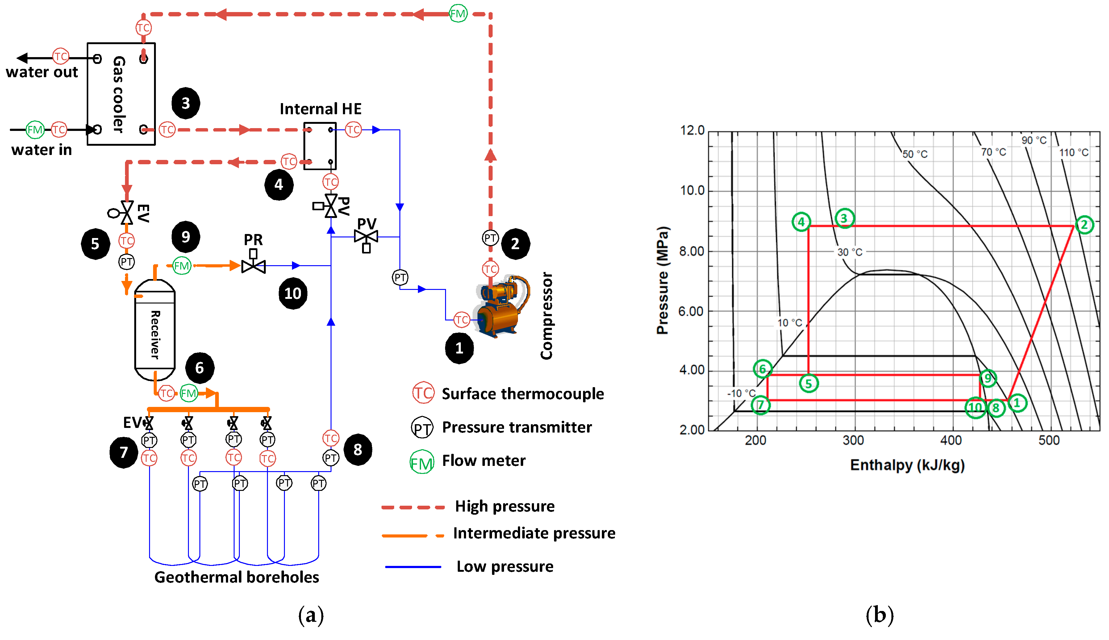
4. Application
For a better understanding of the system and to explore the actions required for performance improvement, a detailed performance analysis was undertaken using the theoretical model. This analysis focused on producing domestic hot water using the DX CO
2 GSHP (water temperature over 50 °C). Eight different cases were considered to be compared against the base case. A combination of the two best cases (#5 & #1) was also investigated in (#9). Two additional cases (BC2 and BC4) were also considered to investigate the effect of the number of boreholes. All system parameters that were different from those of the base case are presented in
Table 6. One by one each parameter was changed in isolation for each case (#1 to #8, BC2 and BC4) to evaluate the effect of the seven following parameters:the degree of superheat at the compressor suction (Δ
Tsh_comp), inlet water temperature to the gas cooler (
Tin_water), CO
2 gas cooler outlet temperature (
Tout_CO2), intermediate pressure (
Preceiver), water mass flow rate (
), IHE efficiency (
εIHE) and number of boreholes in GHE. To solely investigate the effect of one parameter at a time, the optimum pressure control was not adopted here for the parametric analysis and the CO
2 outlet temperature from the gas cooler was fixed. Superheat controls at the borehole outlet and at the compressor suction were combined here into one control at the compressor suction and the entire CO
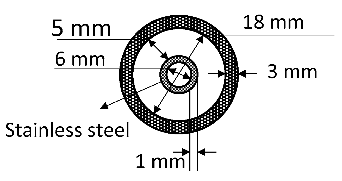
2 flow goes through the IHE. For the parametric study, the gas cooler was a co-axial countercurrent heat exchanger with a total length of 15 m and the cross section is presented in
Figure 4. The overall heat transfer coefficient (U) of the gas cooler varied from case to case and with the evaporating temperature due to changes in CO
2 mass flow rate and properties (UA
gc changes from 0.12 to 0.3 kW/K).
4.1. Result Presentation
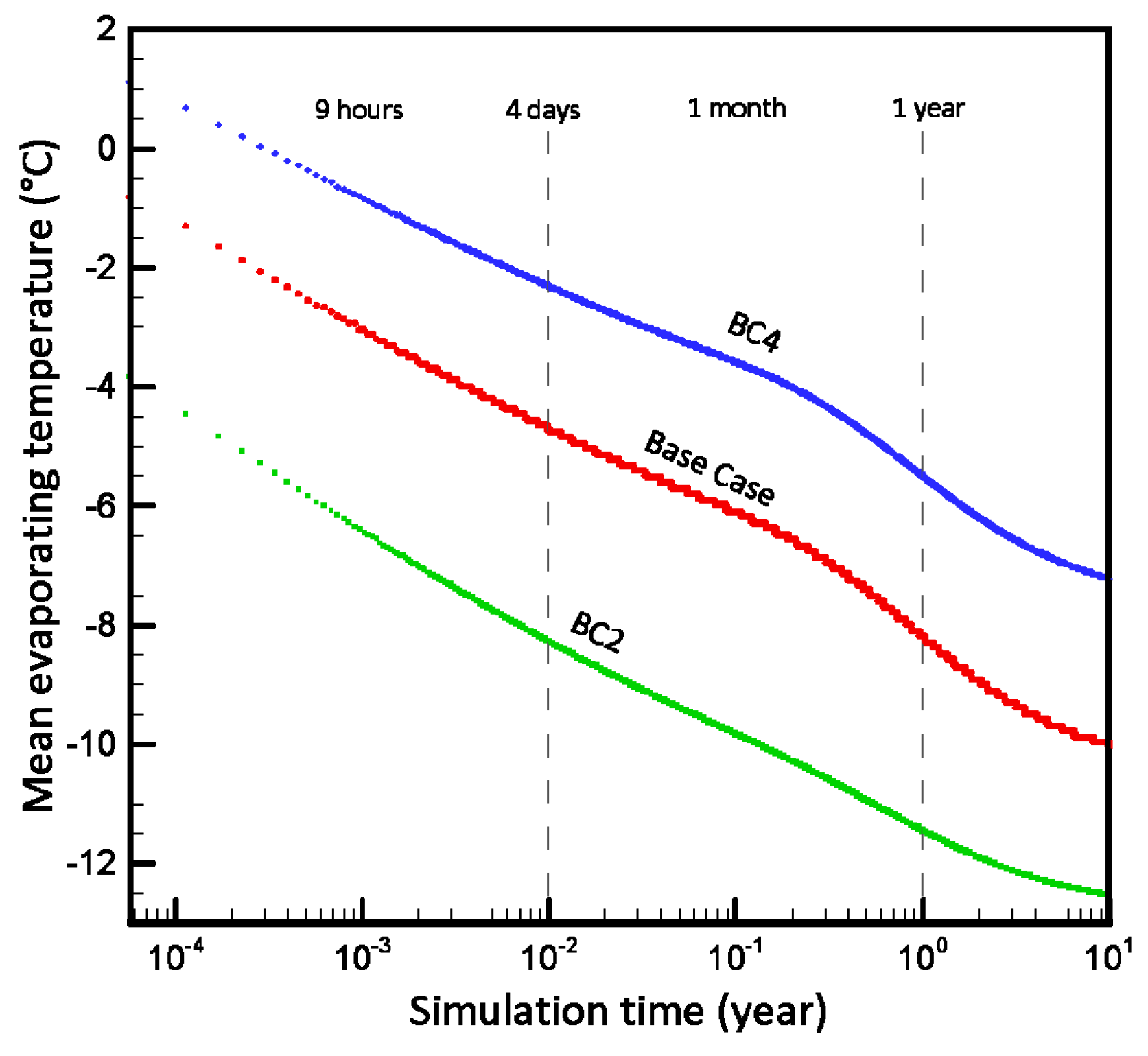
Simulation results summarize the detailed system characterization by presenting the effects of several parameters on COP, gas cooler heating capacity, compressor-work, discharge pressure, water outlet temperature, total borehole extraction rate and borehole pressure drop over the mean evaporating temperature. The evaporating temperature of the heat pump during operation depends on the amount of heat extracted from the soil over time, borehole performance and the soil thermal response. A relatively wide range is presented here for the mean evaporating temperature that corresponds to the transient behavior of the system during 10+ years. For instance, the evaporating temperature drops from the initial value to −8 °C, −5.5 °C and −11.5 °C after one year of continious operation for the base case, BC4 and BC2, respectively (
Figure 5). For other cases, the evaporating temperature values are between those of the BC2 and BC4 presented in
Figure 5.
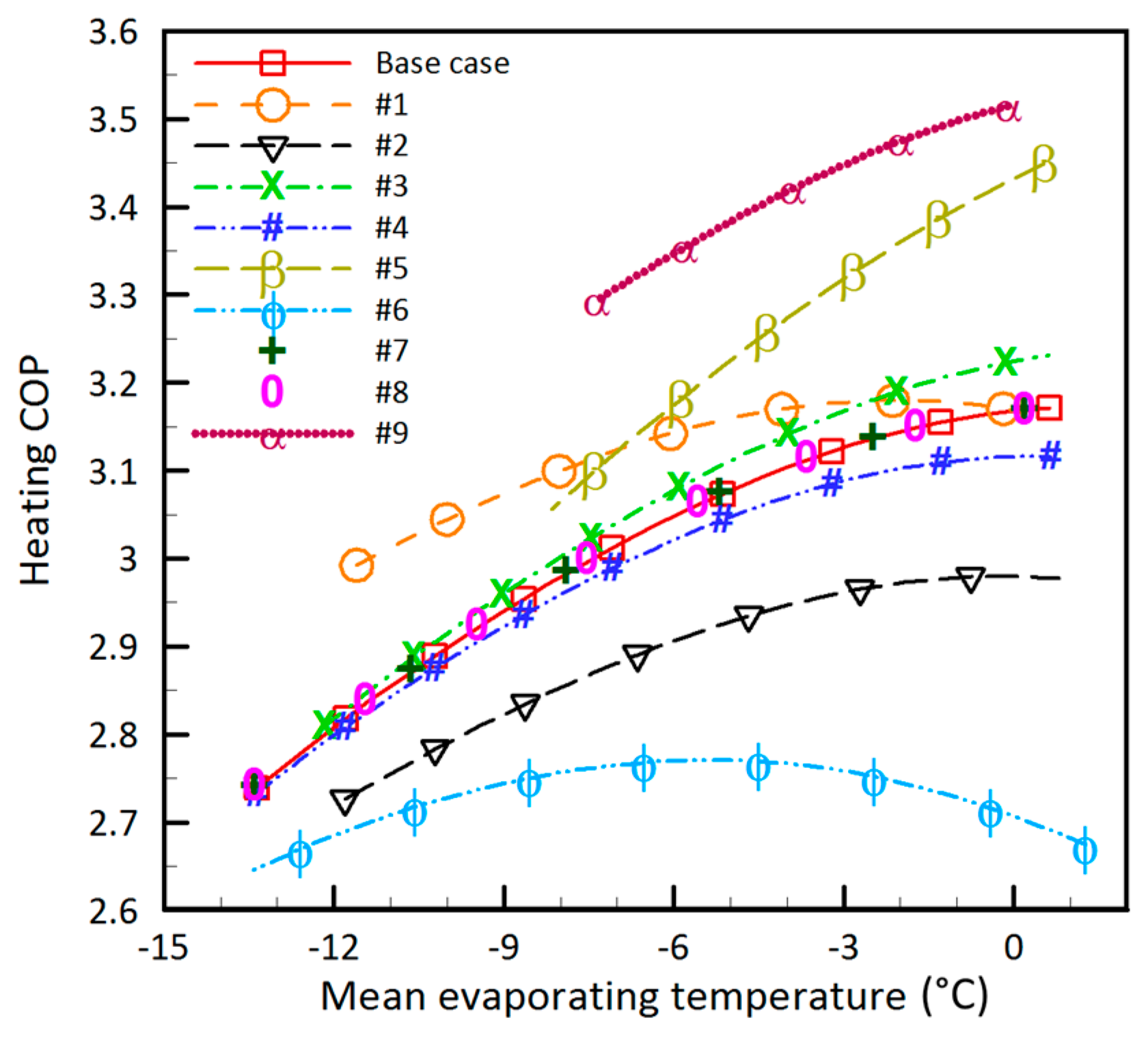
4.2. The Effect of Water Mass Flow Rate
The effect of water mass flow rate was studied in cases #5 and #6. As shown in
Figure 6, among the cases from #1 to #8, for evaporating temperatures from −6 °C to 0 °C, the highest and the lowest COP were presented by case #5 (
= 0.03 kg/s) and case #6 (
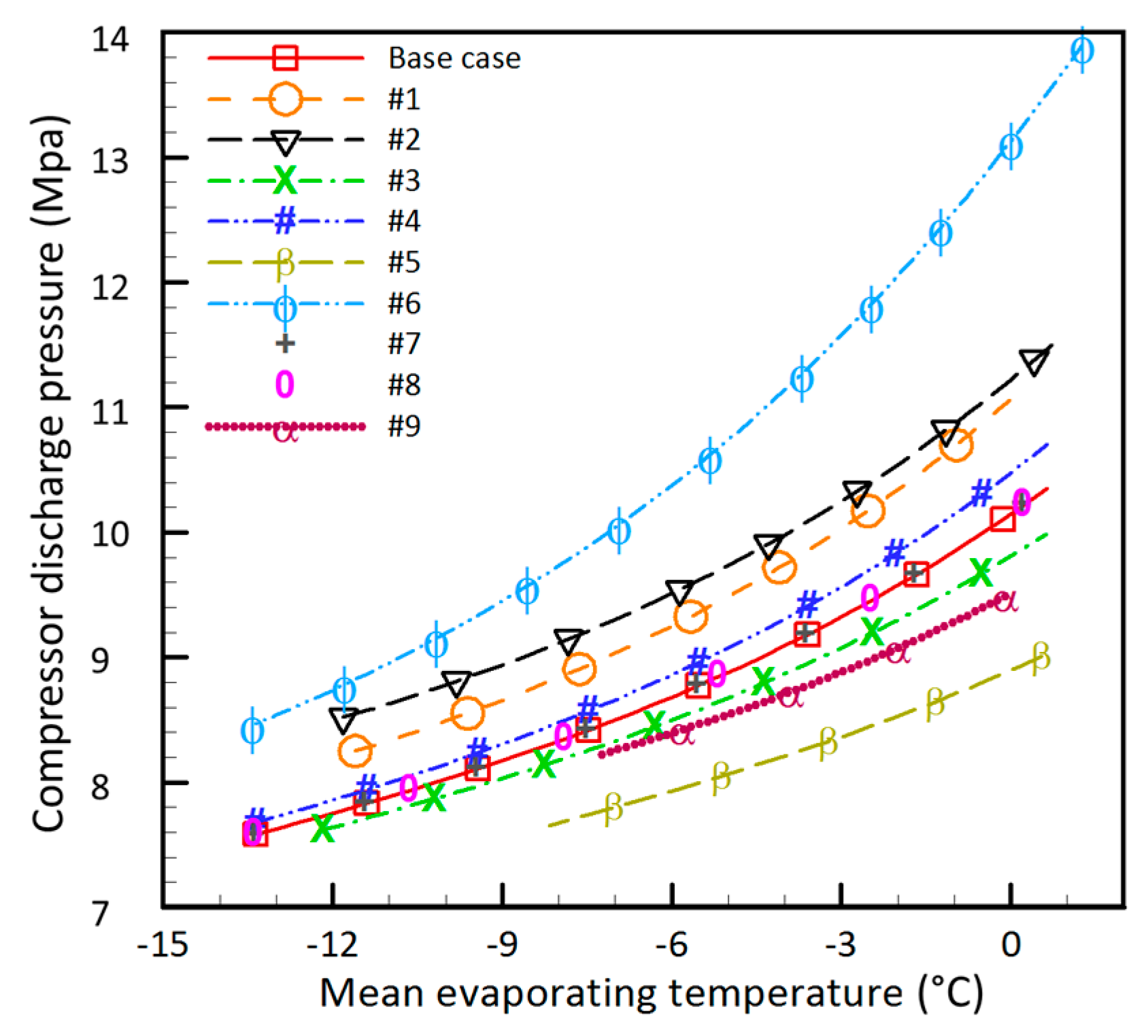
= 0.02 kg/s), respectively. For instance, at 0 °C evaporating temperature, case #5 offers up to 8% higher COP than the base case. On the other hand, reducing the water mass flow rate (case #6) significantly reduces the system COP by 15% at evaporating temperature of 0 °C in comparison with the base case. This is due to the fact that under the same CO
2 gas cooler outlet temperature the discharge pressure is significantly lower for case #5 compared to case #6 (
Figure 7). However, as shown in
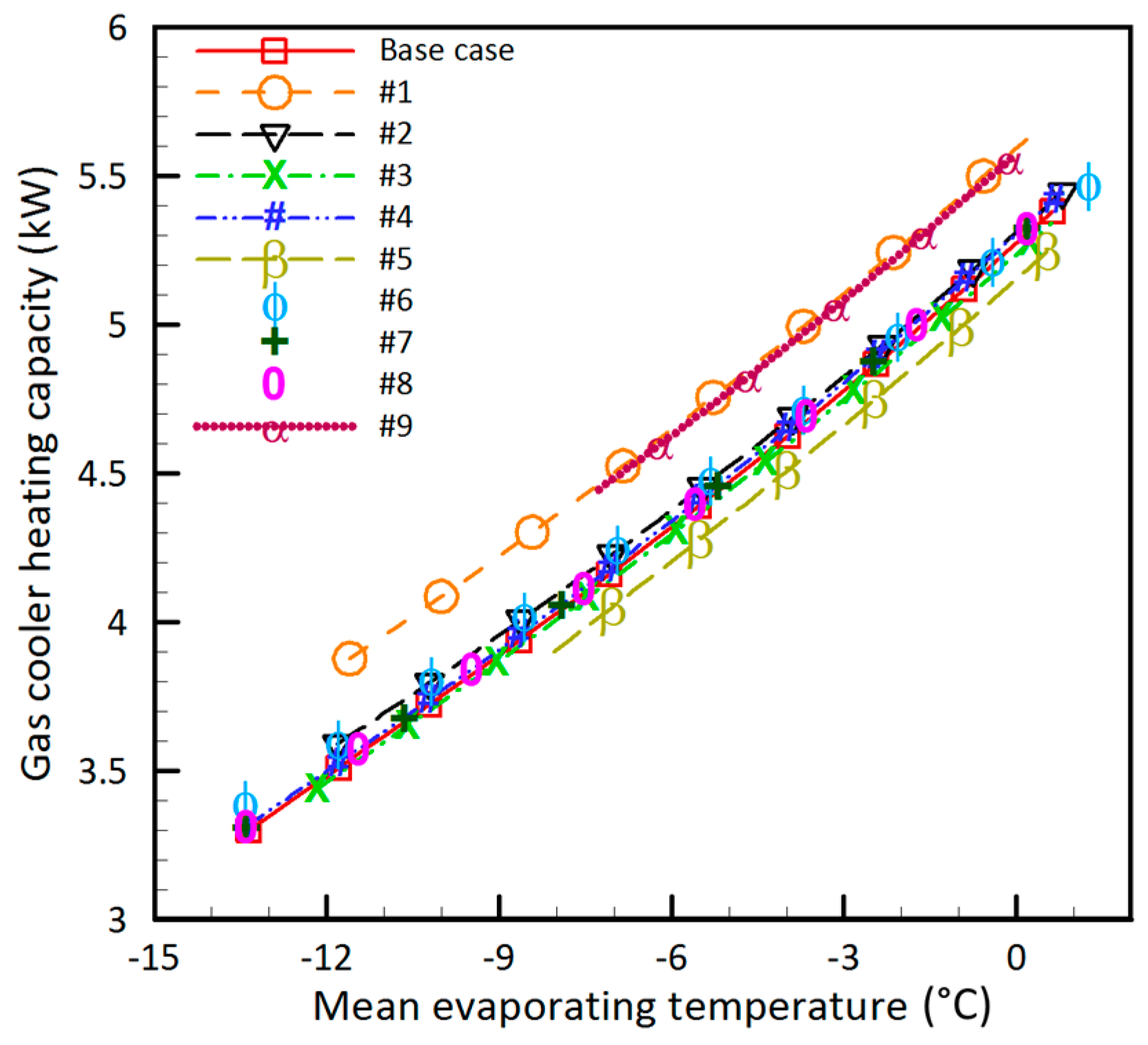
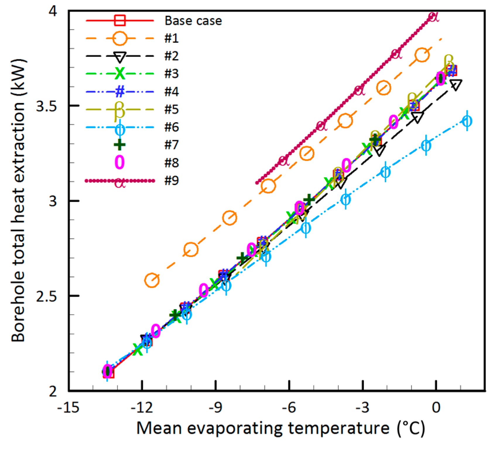
Figure 8, gas cooler heating capacity in case #5 and #6 differs slightly from the base case. Borehole extraction rate in case #5 shows a slight difference from the base case, while in case #6, it is 6% lower than that of the base case (
Figure 9).
4.3. The Effect of CO2 Gas Cooler Outlet Temperature
Reducing the CO
2 outlet temperature of the gas cooler (case #1) positively influences COP, particularly at low evaporating temperatures (up to 6% at −12 °C). The gas cooler heating capacity improves because of the increase in the discharge pressure (
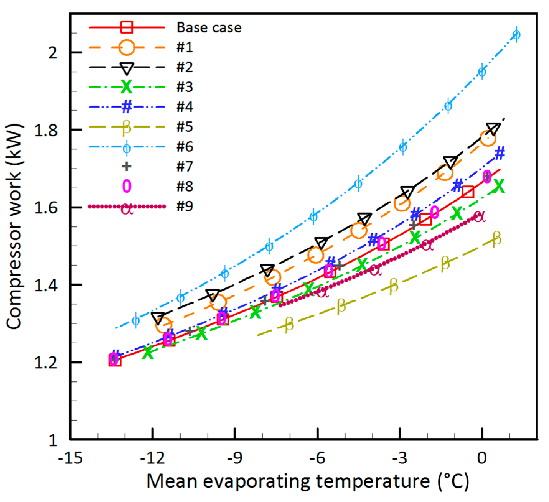
Figure 7). Meanwhile, the compressor work increases (
Figure 10) to discharge CO
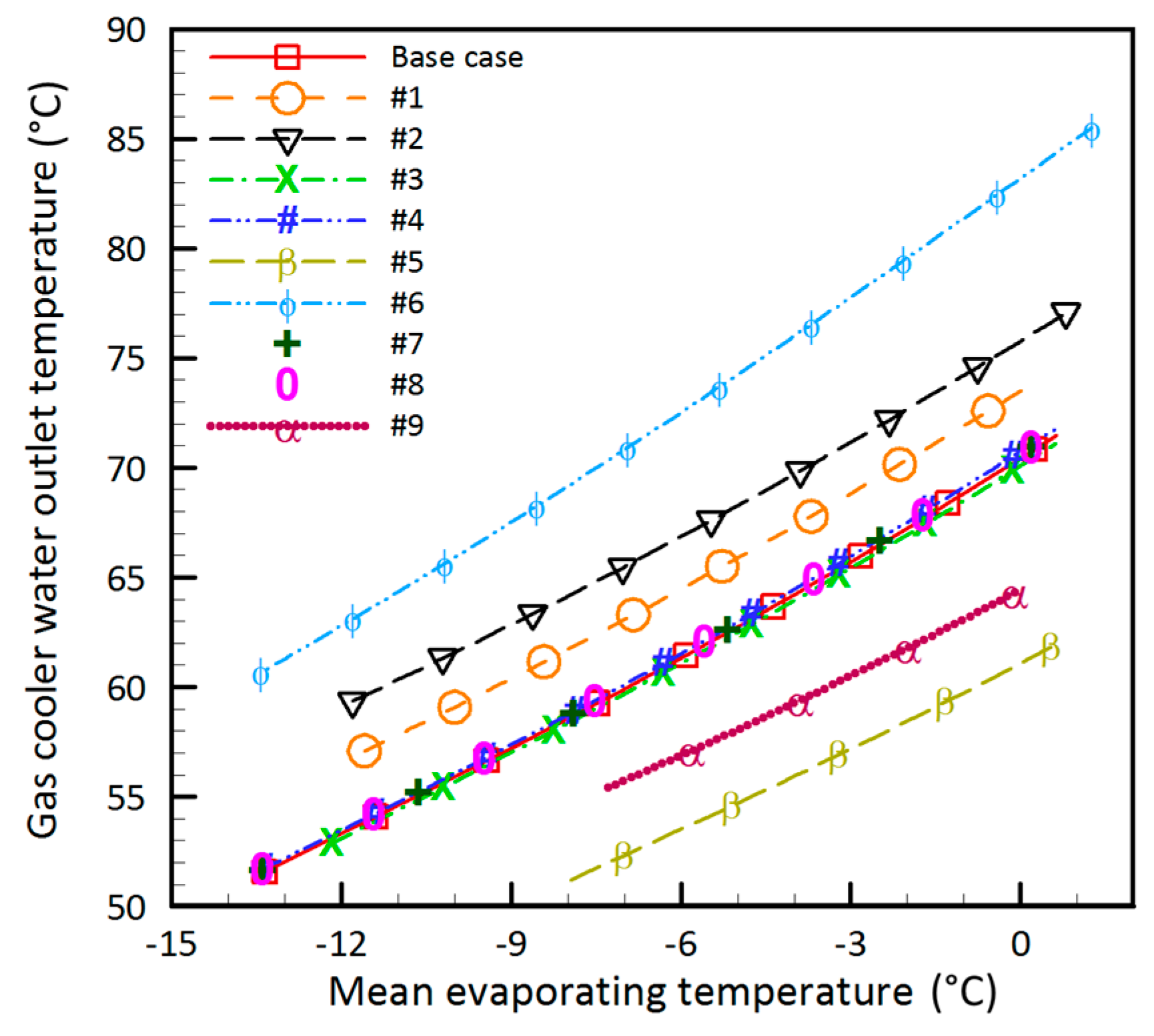
2 at a higher pressure. This is mainly due to the superior gas cooler performance at specific pressure and temperature conditions. Reducing the gas cooler outlet temperature also increases the liquid CO
2 mass flow rate into the boreholes and consequently enhances the total borehole extraction rate. Together with the higher work of the compressor and the higher gas cooler heating capacity, the water outlet temperature increases for the whole range of evaporating temperature (
Figure 11).
4.4. The Effect of Inlet Water Temperature to the Gas Cooler
Case #2 was designed to investigate the effect of water temperature entering the gas cooler. Increasing the water inlet temperature reduces the COP up to 6% due to the higher discharge pressure and therefore higher compressor work (
Figure 7 and
Figure 10). In other words, to keep the outlet CO
2 temperature constant, the compressor needs working more (
Figure 10) to discharge the fluid at a higher temperature and pressure.
4.5. The Effect of Superheat
The effect of superheat at the suction of the compressor is highlighted by cases #3 and #4. Under given conditions, higher superheat marginally improves the COP. At higher compressor suction temperatures, CO2 specific volume increases and therefore reduces both the mass flow rate and the compressor work. With a trivial effect on the gas cooler heating capacity, higher superheat at the compressor suction, slightly improves the COP of the system.
4.6. The Effects of IHE efficiency and the Intermediate Pressure
According to the results of cases #7 and #8, the intermediate pressure and the efficiency of the IHE do not noticeably affect the COP, qgc, water outlet temperature and the total borehole extraction rate.
4.7. The Combined Effect of CO2 Gas Cooler Outlet Temperature and Water Flow Rate
Cases #1 and #5 (the cases with the highest COP) were coupled (case #9) to investigate the effect of
Tout_CO2 and
together, on the performance of the system. Here,
Tout_CO2 and
were changed similar to cases #1 and #5, respectively. Results show a significant improvement in the COP of the system (up to 12% higher than the base case). Gas cooler capacity is also increased by 7.5% compared to the base case. Moreover, as shown in
Figure 9, case #9 offers the highest total borehole extraction rate among all cases for evaporating temperatures from −6 °C to 0 °C (up to 10% at 0 °C compared to the base case). Apparently, proper control over the discharge pressure of the compressor and appropriate design of the gas cooler significantly improve the performance of a DX-CO
2 GSHP.
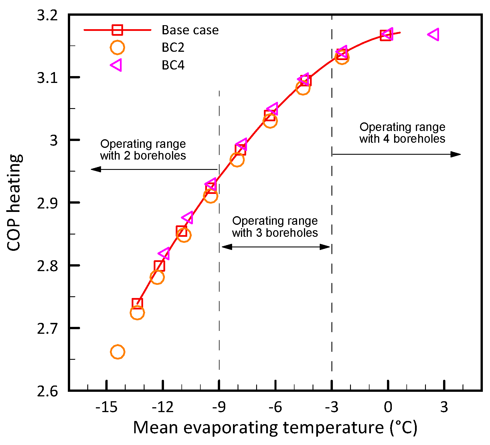
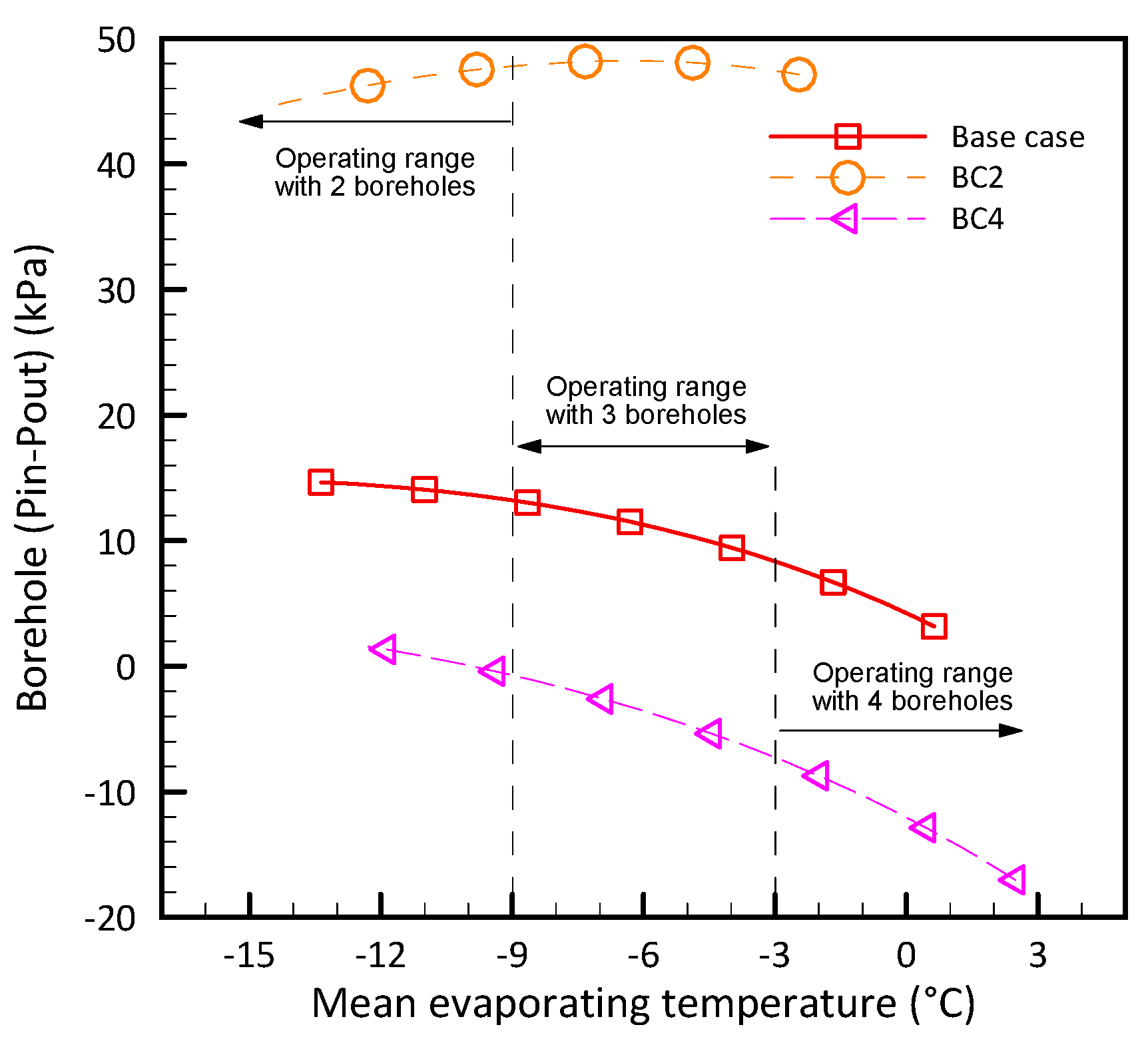
4.8. Effect of the Number of Boreholes
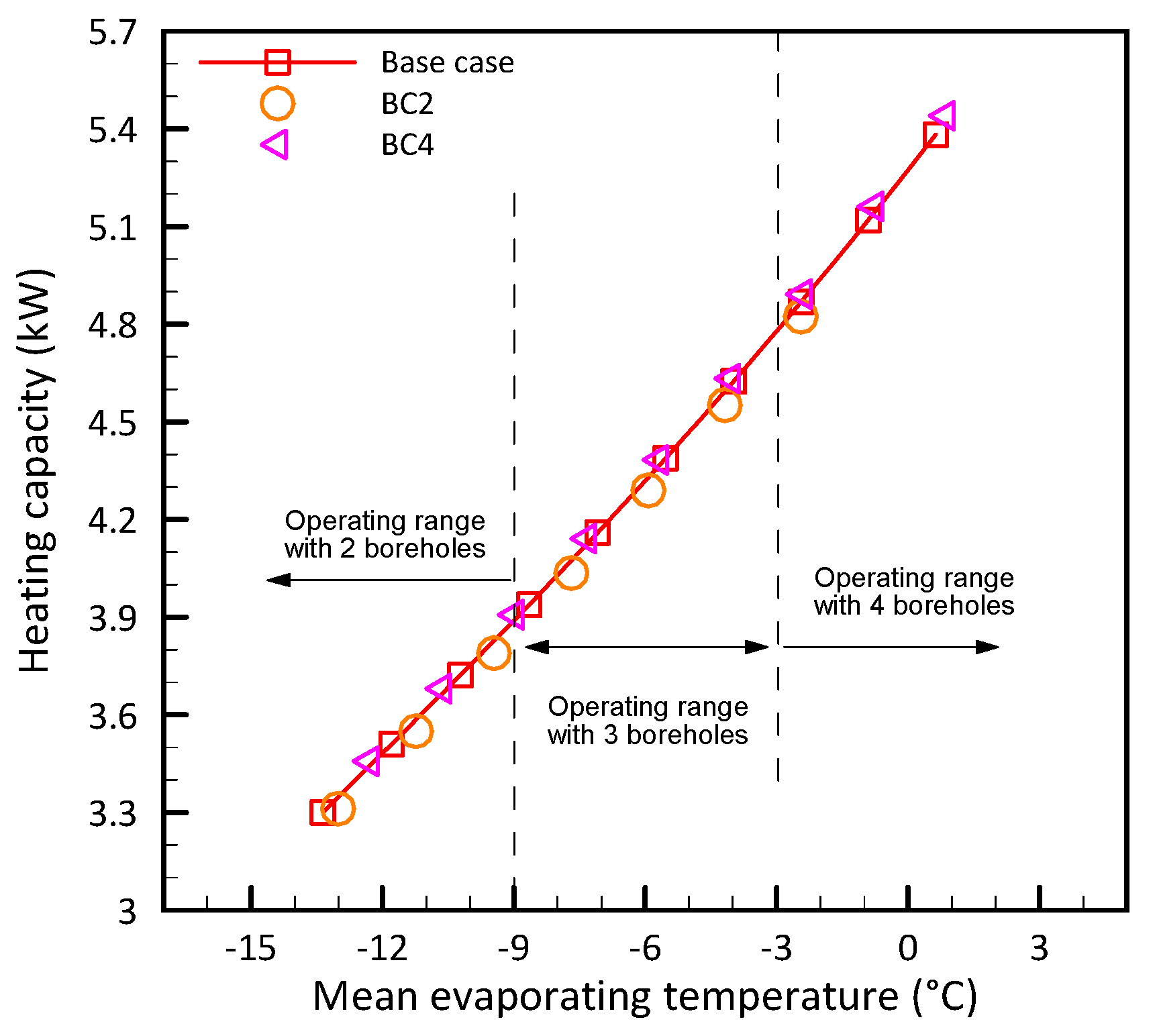
The effect of the number of boreholes on COP and gas cooler heating capacity is highlighted by cases BC2 and BC4 in
Figure 12 and
Figure 13, respectively. According to these figures, the system with a lower number of boreholes mainly operates with a lower evaporating temperature. Reducing the number of boreholes results in a smaller heat transfer area inside the ground and a higher CO
2 flow rate in each borehole. Therefore, to satisfy a certain superheat, the system needs to operate at a lower evaporating temperature and this creates a larger temperature difference between the CO
2 and the ground. Eventually, the gas cooler heating capacity is limited in the case with two boreholes. The average heating capacity of the gas cooler in the case with two boreholes is 28% less than the case with four boreholes. A similar phenomenon has been observed experimentally in [
37]. Although the flow rate per borehole is reduced by increasing the number of boreholes, the overall thermal resistance of the borehole does not change significantly. The calculated thermal resistances of the base case, four and two boreholes are 0.230, 0.232, and 0.228 [M·K/W], respectively.
As shown in
Figure 12 and
Figure 13, although the heat pump works at lower evaporating temperatures with fewer boreholes (
Figure 5), heat pump performance parameters (COP and heating capacity) follow an identical curve. However, in
Figure 14, the difference between the inlet and outlet pressure (pressure drop) of the borehole in BC2, BC4 and the base case is more evident. Negative values in
Figure 14 imply that the CO
2 flow pressure gain due to gravity is higher than the acceleration and friction pressure drop. Using two boreholes increases the pressure drop by up to 5 times more than that of the base case at certain evaporating temperatures (e.g., at −3 °C). There is a pressure gain in the borehole for BC4 over almost the whole operating range of the system. For BC4 and the base case, the pressure drop decreases as the evaporating pressure increases. However, the opposite behavior is observed from −15 °C to −5 °C for BC2 (pressure drop increases as the evaporating pressure increases).
5. Conclusions
While DX CO2 GSHP is an energy efficient and environmental friendly option for providing space heating and hot water in buildings, the lack of related technical knowledge of these systems hinders its application in the market. To address this issue, a previously developed theoretical model was modified and validated using experimental results. The experiments were conducted using a test bench built and commissioned at CanmetENERGY research laboratory, Varennes, Canada. A detailed performance analysis of the system was numerically carried out for water heating to identify the important parameters and their effects. Parameters, including the degree of superheat at the compressor suction, inlet water temperature to the gas cooler, CO2 gas cooler outlet temperature, intermediate pressure, water mass flow rate, IHE efficiency and number of boreholes in the GHE were selected. The effect of these parameters on the COP of the system, heating capacity of the gas cooler, compressor work, discharge pressure, water outlet temperature and total borehole extraction rate was investigated.
Results showed that efficient domestic hot water heating (COP of over 3) with relatively high temperature difference between inlet and outlet of the water tank (30 °C), is achievable using transcritical DX-GSHP systems. However, improper control of some parameters such as gas cooler CO2 outlet temperature and discharge compressor pressure can degrade the system performance up to 25%. Beside the proper design of the gas cooler, the controlling parameters (e.g., the discharge pressure) need to be set correctly as a base for the application. In addition to the heat capacity improvement of the gas cooler, proper control of the system allows the boreholes to work at their full capacity and eventually improves the performance of the system. Moreover, the size of the ground heat exchanger and the number of active boreholes significantly affect the evaporating temperature and consequently the performance of the system. For instance, the COP of the system dropped to 3.06 from 3.17 after a month of continuous operation in the base case (with three boreholes) of this study. However, after the same period, the COP of scenarios with four and two boreholes dropped to 3.11 and 2.89, respectively.


