A Key Review of Non-Industrial Greywater Heat Harnessing

Abstract
:1. Introduction
1.1. Background
- Consume minimal amounts of energy
- Be energy efficient
- Source their energy from renewable sources
1.2. Scope
1.3. Objectives
- The various output patterns of GW, and conventional methods used to source this data
- Commercially mature GW harnessing technologies used at different levels along sewage lines
- A critical analysis of the shortcomings of these technologies and their underlying hurdles, not making it to mainstream conventional buildings
- Upcoming ideas and technologies for harnessing along with the associated applications of potential usage
2. Characteristics of Greywater
2.1. Collection of Production Data
- (a)
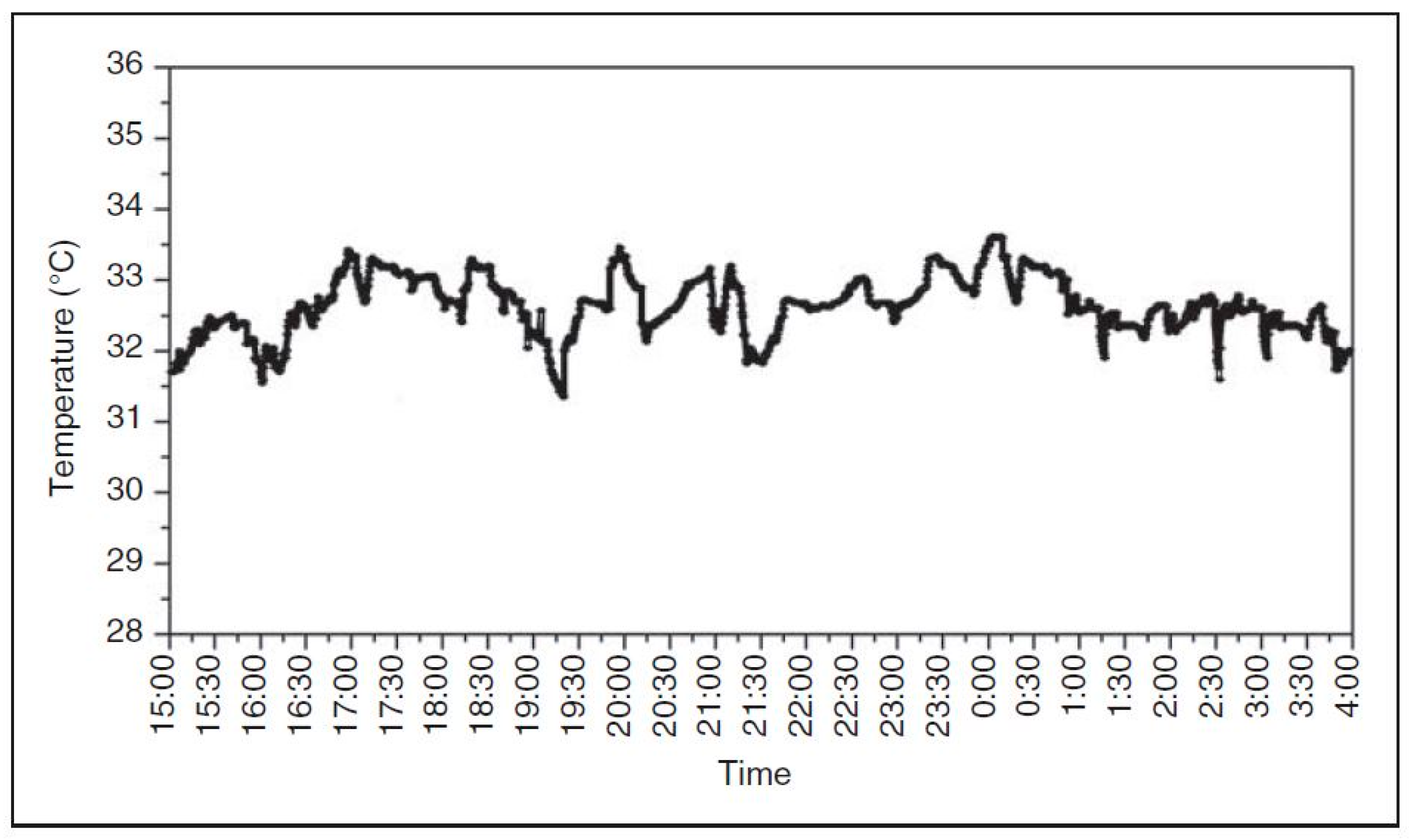
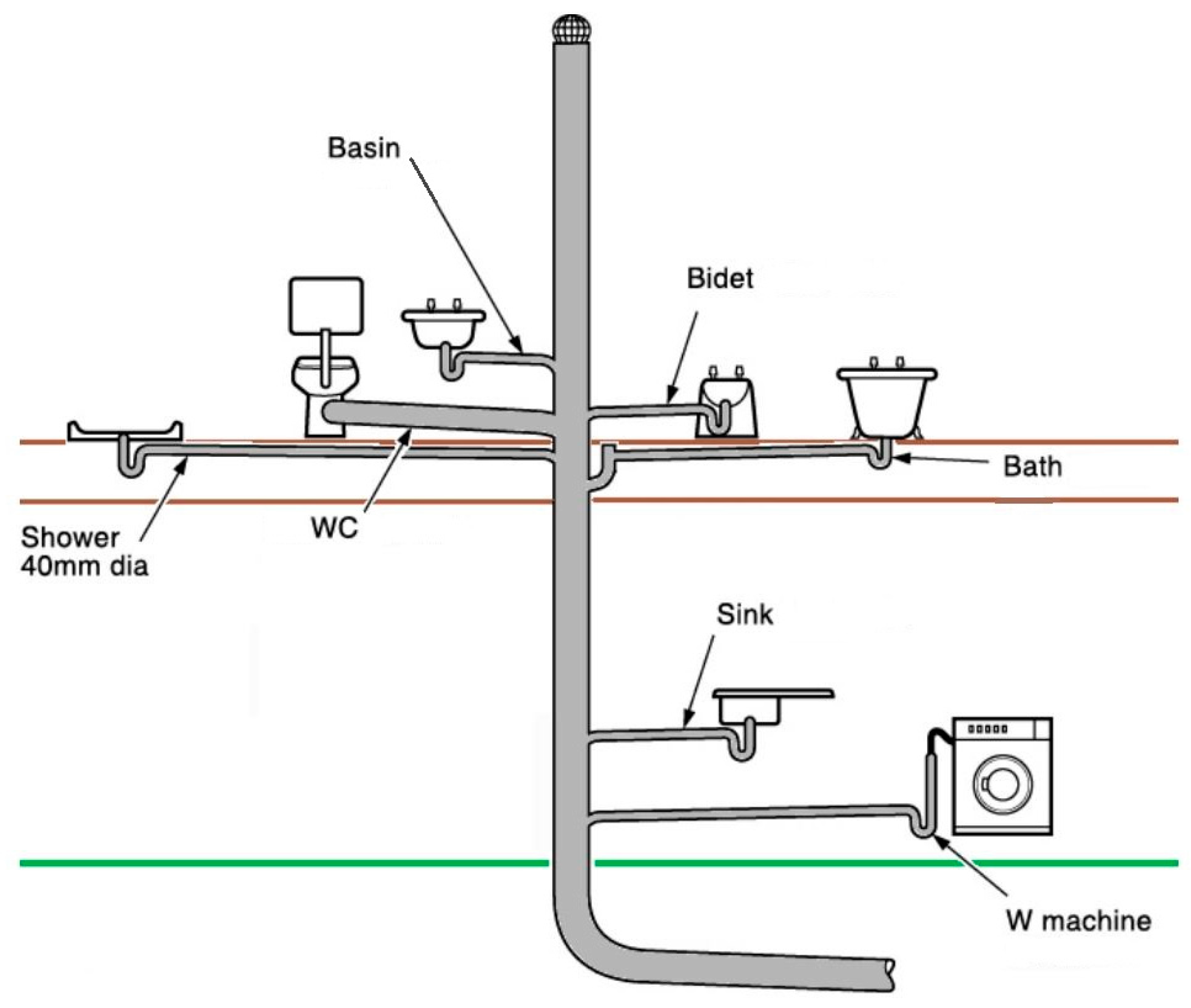
- Experimental/Field study: This is the more authentic way of collecting data, although considerable noise is present. One reason is, due to the unpredictable nature of the outflow of GW, that is highly dependent on the mood and characteristics of each user [10]. In a field study in the UK based on 25 houses, the water usage varied by a factor of seven, despite having homogenous specifications and building designs.For the application of heat harnessing, the flow rates and temperatures of the GW, are the only quantities measured at the outlet pipe of each appliance [11]. The monitoring device is attached to the specific pipe of the appliance, and not the stack of Figure 3, as it would include black water [22]. There are three main components used for monitoring data:
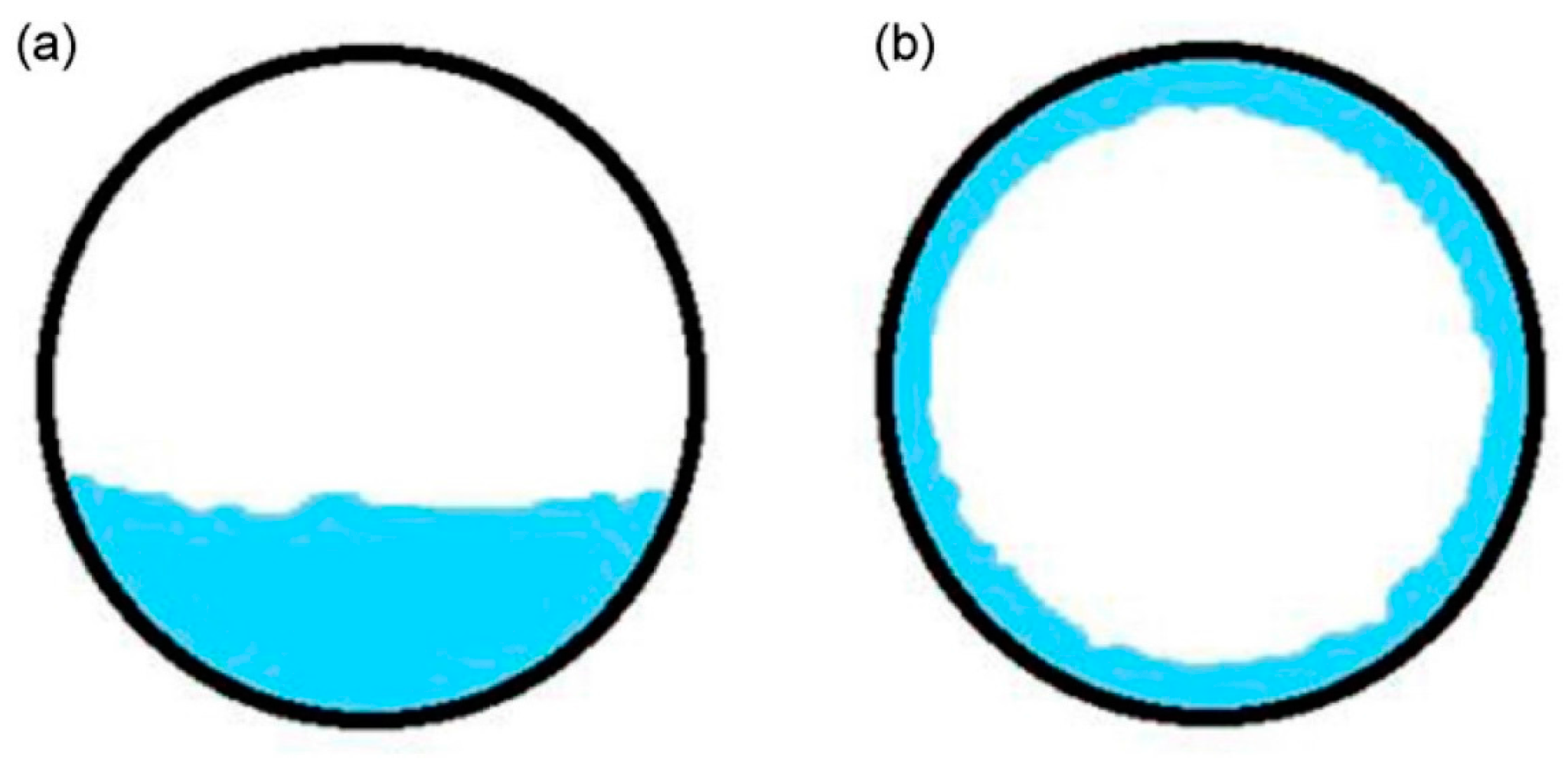
- The instruments: Due to the restrictive layout of the pipes and the inability to obstruct the flow, because of biofilm deposits and pressure losses, flow is usually measured with a non-intrusive and non-invasive device. The most commonly used flow-meters, pertaining to these characteristics are ultra-sonic flow meters functioning on the Doppler effect [24]. Magnetic induction meters are also used, but are less common. Most clamp-on ultrasonic meters are in the £500–2000 range, depending on the specifications and accuracy required. The output of such devices are in the form of pulses whose frequency is proportional to the flow rate [10]. Usually the calibration of these meters, can be done manually with timed volume measurement techniques, depending on the accuracy required [11].In terms of temperature measuring devices, a non-intrusive and non-invasive instrument is also used, for the same reasons. For sensors clamped on the pipe, it is important that errors due to the ambient temperature do not affect the measurement [12]. For some circumstances, sensors on probes can be used depending on the accuracy required and the access from the piping. The most common sensors include thermocouples and resistance based semiconductors, with prices starting at about £10 to about £500, depending on the materials and accuracy required [25]. These sensors operate on the Seeback principle and the change in resistance with temperature, respectively. Since these devices have self-adhesives or clamps, the accuracy is quite limited when measuring the flow in a half-full pipe [26]. Infrared sensors and fibre optic sensors based on the principles of radiation and the Raman effect, respectively, are more accurate substitutes. Their prices range from £100–£2000, depending on the specification and accuracy.
- Power source: There are three mechanisms to power a data collecting instrument. The first type requires an external DC-Voltage in the range of 0–30 V. The second type can be plugged into normal AC sockets in a building. While the third type are self-powered by internal rechargeable batteries, the connected data logger or the data transmitting source.
- Data transmitter: For acquiring long term data, a simple display LED on the instrument, does not suffice. There must be an external hard disk to record the time variation of data, over the period of observation, usually a few months [22]. This data is either transmitted wirelessly or through a communications cable i.e., Modbus, Ethernet, USB, etc. In some circumstances, it is transmitted directly to a hard disk via a connected data logger [11]. The frequency of transmission can be pre-defined depending on the precision required. Most household experiments use 5 to 10 min intervals, to record readings [10]. After acquiring the data, a cleaning process is required, to filter out errors for useful information [22].
- (b)
- Theoretical: This is a relatively unconventional way, but with advancements in artificial intelligence and computing algorithms, it is gaining popularity [27]. Normally the inflow of water from the main utility connection and/or the output from a boiler is measured. Based on statistical algorithms and artificial intelligence, the consumption and characteristics of the GW, at different points in the house are computed [15]. This method is called flow trace analysis [28]. Usually the model is validated based on field studies and has proved a reliable source usually having an accuracy of about 90% [27]. The versatility of these tools make it quite economical, considering that, they can be adjusted to different households and regions having different dynamics [27]. These theoretical models can also be economically used for forecasting, analysing the savings from harnessing devices and demand side management techniques [29]. In some circumstances, data with less precision is extrapolated to make it more precise over longer or more detailed time durations [10]. On the input of approximately 1 million users, the American Water Works Association, has developed one such comprehensive statistical prediction model [15]. Similarly, a water consumption calculator was launched in the UK for households, through a survey [13]. Based on statistical algorithms and input from over 100,000 users, on questions about usage patterns, a large dataset for domestic water usage was formulated. The ultimate objective of is similar to that of a smart meter, where households can assess their daily usage of water and associated heating energy, to eventually control wastage.
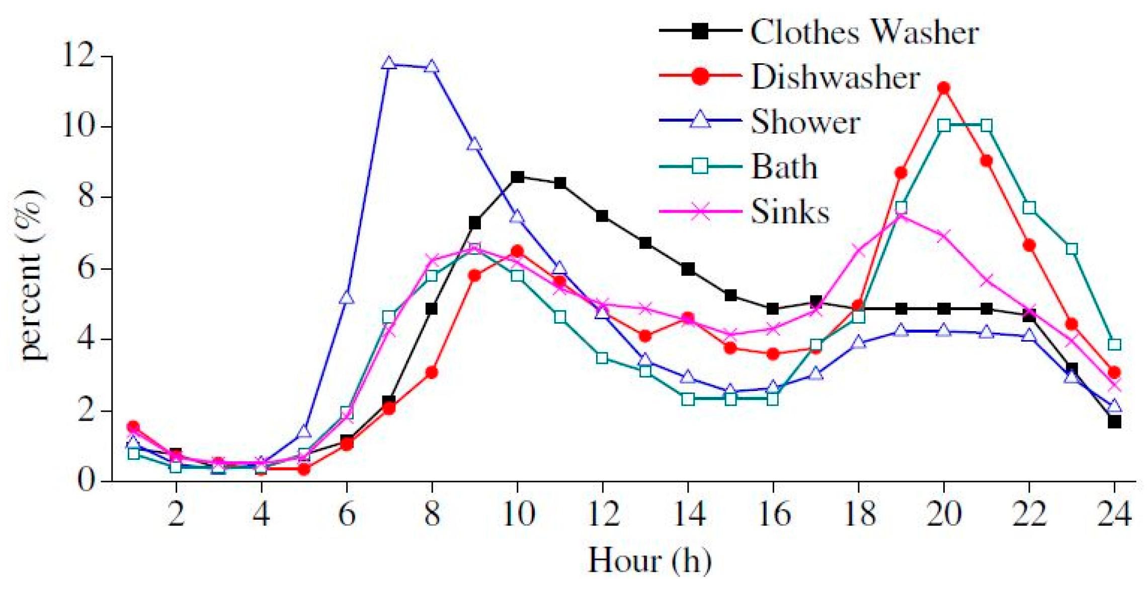
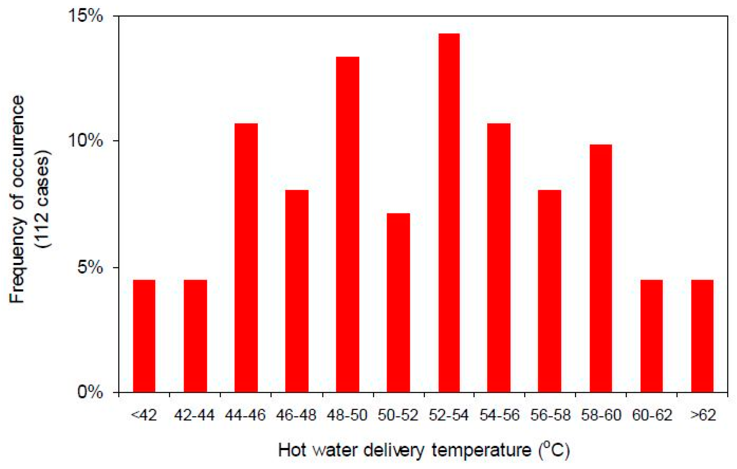
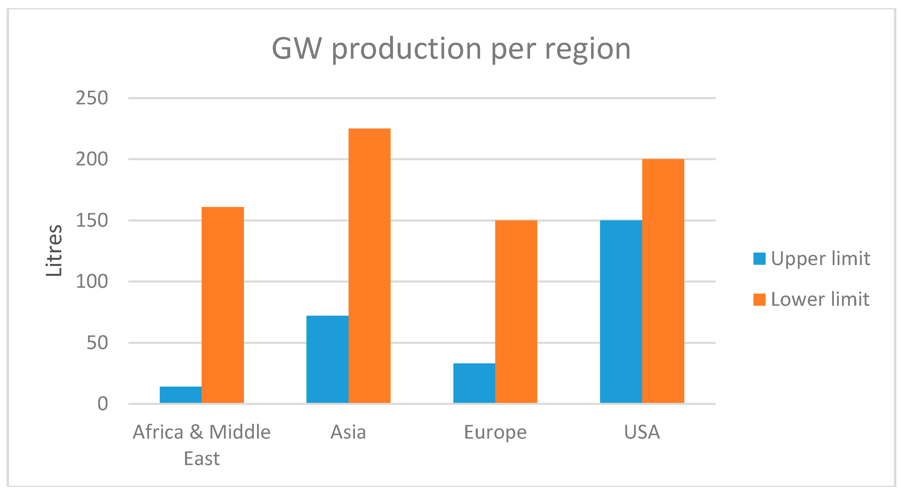
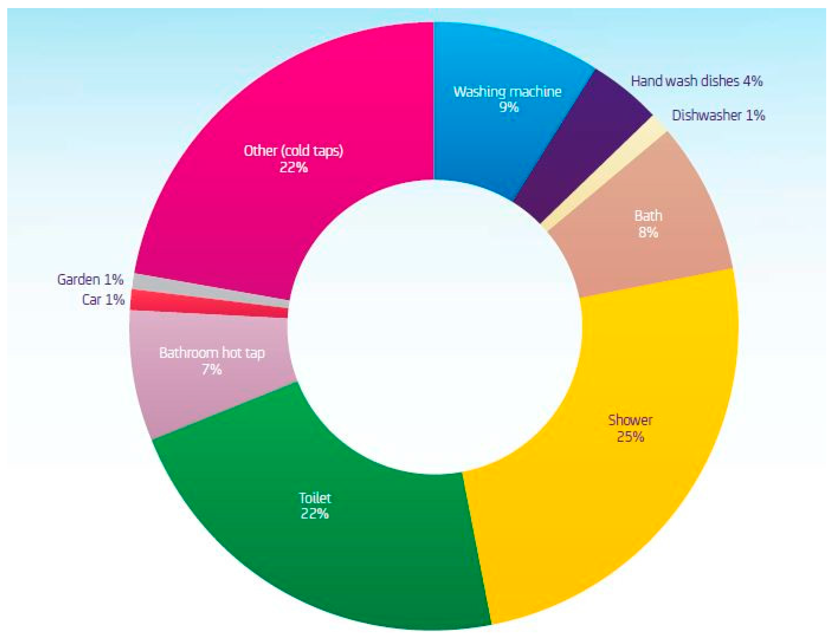
2.2. Production Patterns
2.2.1. Residential Buildings
- Showers/baths
- WC basins
- Dishwashers
- Kitchen sinks
- Washing machines
Showers/Baths & WC Basins
Dishwashers and Kitchen Sinks
Washing Machines
2.2.2. Commercial Buildings
2.3. Potential Usage
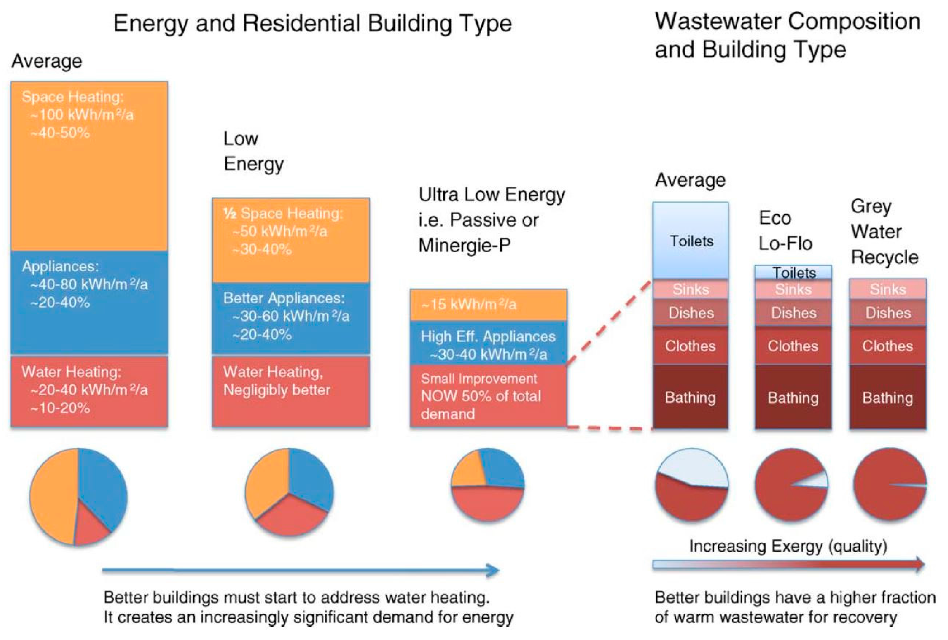
- The temperature profiles and the supply are almost consistent throughout the year, irrespective of the atmospheric conditions making, it predictable and reliable.
- The quantities and hence harnessing potential is quite significant especially in commercial buildings.
- Heat harnessing units are quite versatile in operation, and can be efficiently integrated into conventional plumbing systems.
- Most harnessing units have passive technologies, limiting maintenance and operational costs [35].
- These units extend the life of domestic water heaters, as their usage decreases [35].
- In countries having warm climates, there exists a possibility to remove heat from incoming water, to further cool it down, and add it to GW. Based on past experiences, it is more economical to use a co-generation facility for both heating and cooling [12].
3. Mature Heat Harnessing Technologies
3.1. Levels of Heat Harnessing
3.2. Heat Exchangers
3.2.1. Type
3.2.2. Orientation
3.2.3. Location
3.2.4. Anti-Fouling Mechanisms
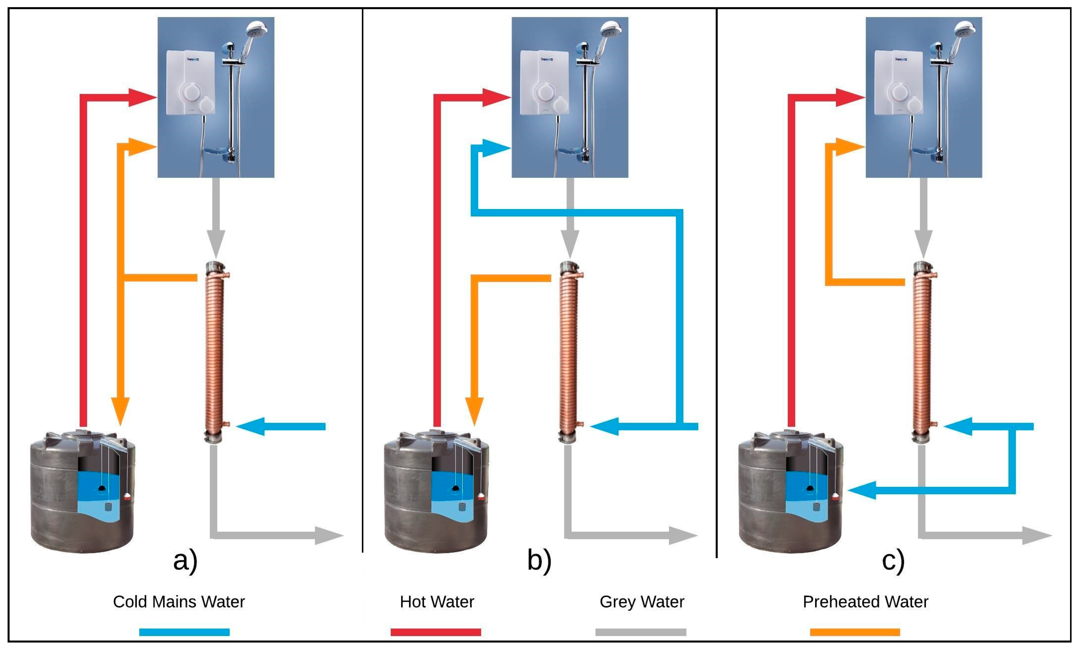
3.2.5. Operation Strategy
- (a)
- preheated water can flow to both the storage and appliance—balanced condition
- (b)
- preheated water flows only to the storage—unbalanced condition
- (c)
- preheated water flows only to the appliance—balanced condition
3.3. Heat Pumps
3.3.1. Type
3.3.2. Type of Heat Exchangers for the Evaporator and Condenser
3.3.3. Working Fluid
3.3.4. Location of Installation
3.3.5. Reversibility of Cycle
3.4. Hybrid Systems
3.4.1. With Conventional and Renewable Technologies
3.4.2. HE/HP Hybrids
4. Constraints and Shortcomings in Harnessing
- (a)
- Prices compared to conventional fossil fuels
- (b)
- Harnessing size and possible linkage of supply with demand
- (c)
- Enhancing the heat density for better utilization
5. Potential Heat Harnessing Applications and Upcoming Technologies
6. Conclusions
Author Contributions
Conflicts of Interest
Abbreviations
| GW | Grey water |
| BW | Black water |
| DC | Direct Current |
| AC | Alternating Current |
| min | Minutes |
| CO2 | Carbon Dioxide |
| HE | Heat Exchanger |
| HP | Heat Pump |
| WWTP | Waste Water Treatment Plant |
| MW | Mega Watts |
| GFX | Gravity Film Exchangers |
| CFR | Critical Flow Rate |
| HFC | Fluorinated hydrocarbon |
| CFC | Chlorofluorocarbon |
| COP | Coefficient of Performance |
| WW | Waste Water |
| ASHP | Air Source Heat Pump |
| DH | District Heating |
| LHS | Latent Heat Storage |
| SHS | Sensible Heat Storage |
| PCM | Phase Change Material |
References
- International Energy Agency. Technology Roadmap: Energy Efficient Buildings, Heating and Cooling Equipment; International Energy Agency: Paris, France, 2011. [Google Scholar]
- International Energy Agency. Tracking Clean Energy Progress 2016. In Energy Technology Perspectives 2016; International Energy Agency: Paris, France, 2016; pp. 1–82. [Google Scholar]
- Christoff, P. The promissory note: COP 21 and the Paris Climate Agreement. Environ. Politics 2016, 25, 765–787. [Google Scholar] [CrossRef]
- Schnieders, J.; Feist, W.; Rongen, L. Passive Houses for different climate zones. Energy Build. 2015, 105, 71–87. [Google Scholar] [CrossRef]
- Stephan, A.; Crawford, R.H.; de Myttenaere, K. A comprehensive assessment of the life cycle energy demand of passive houses. Appl. Energy 2013, 112, 23–34. [Google Scholar] [CrossRef]
- Meggers, F.; Leibundgut, H. The potential of wastewater heat and exergy: Decentralized high-temperature recovery with a heat pump. Energy Build. 2011, 43, 879–886. [Google Scholar] [CrossRef]
- International Energy Agency. Renewable Energy: RD & D Priorities; International Energy Agency: Paris, France, 2006; p. 221. [Google Scholar]
- Vatansever, D.; Siores, E.; Shah, T. Alternative Resources for Renewable Energy: Piezoelectric and Photovoltaic Smart Structures. Glob. Warm. Impacts Future Perspect. 2012, 263–290. [Google Scholar] [CrossRef]
- Yeatman, E.M. Energy harvesting–Small scale energy production from ambient sources. In Proceedings of the SPIE 7288, Active Passive Smart Structures and Integrated Systems, San Diego, CA, USA, 9–12 March 2009. [Google Scholar] [CrossRef]
- Gill, Z.M.; Tierney, M.J.; Pegg, I.M.; Allan, N. Measured energy and water performance of an aspiring low energy/carbon affordable housing site in the UK. Energy Build. 2011, 43, 117–125. [Google Scholar] [CrossRef]
- Wheatley, A.D.; Surendran, S. Greywater treatment and reuse results from a 50-person trial. Urban Water J. 2008, 5, 187–194. [Google Scholar] [CrossRef]
- Dürrenmatt, D.J.; Wanner, O. A mathematical model to predict the effect of heat recovery on the wastewater temperature in sewers. Water Res. 2014, 48, 548–558. [Google Scholar] [CrossRef] [PubMed]
- Energy Saving Trust. At Home with Water; Technical Report; Energy Saving Trust: London, UK, 2013. [Google Scholar]
- Energy Savings Trust. Measurement of Domestic Hot Water Consumption in Dwellings; Technical Report; Energy Saving Trust: London, UK, 2008; pp. 1–62. [Google Scholar]
- Ni, L.; Lau, S.K.; Li, H.; Zhang, T.; Stansbury, J.S.; Shi, J.; Neal, J. Feasibility study of a localized residential grey water energy-recovery system. Appl. Therm. Eng. 2012, 39, 53–62. [Google Scholar] [CrossRef]
- Nolde, E. Water and energy recycling at a residential passive house. In Proceedings of the Poster Sustainable Building Conference, Graz, Austria, 25–28 September 2013; pp. 1353–1360. [Google Scholar]
- Cautley, D. Drain Water Heat Recovery—A Field Study of Commercial Applications; ECW Report Number 272-1; Energy Center of Wisconsin: Madison, WI, USA, 2013. [Google Scholar]
- Wallin, J.; Claesson, J. Analyzing the efficiency of a heat pump assisted drain water heat recovery system that uses a vertical inline heat exchanger. Sustain. Energy Technol. Assess. 2013, 80, 7–16. [Google Scholar] [CrossRef]
- Al-Jayyousi, O.R. Greywater reuse: Towards sustainable water management. Desalination 2003, 156, 181–192. [Google Scholar] [CrossRef]
- Allen, L.; Christian-smith, J.; Palaniappan, M. Overview of Greywater Reuse: The Potential of Greywater Systems to Aid Sustainable Water Management; Pacific Institute for Studies in Development, Environment & Security: Oakland, CA, USA, 2010. [Google Scholar]
- Association of Plumbing & Heating Contractors Ltd. Sanitary Systems within the Home. Available online: http://www.aphc.co.uk/UNDERSTANDING%20SANITARY%20SYSTEMS%20WITHN%20THE%20HOME.pdf (accessed on 6 September 2017).
- Alsulaili, A.D.; Hamoda, M.F. Quantification and characterization of greywater from schools. Water Sci. Technol. 2015, 72, 1973–1980. [Google Scholar] [CrossRef] [PubMed]
- HM Government. The Buildings Regulation: Drainage and Waste Disposal; RIBA Enterprises Ltd.: Newcastle Upon Tyre, UK, 2015. [Google Scholar]
- National Measurement System. An Introduction to Non-Invasive Ultrasonic. Available online: http://www.tuvnel.com/_x90lbm/An_Introduction_to_Non-Invasive_Ultrasonic_Flow_Metering.pdf (accessed on 6 September 2017).
- Zaloum, C.; Lafrance, M. Drain Water Heat Recovery Characterization and Modeling; Sustainable Buildings and Communitiues, Natural Resource Canada: Ottawa, ON, Canada, 2007; pp. 0–42. [Google Scholar]
- Wallin, J.; Claesson, J. Investigating the efficiency of a vertical inline drain water heat recovery heat exchanger in a system boosted with a heat pump. Energy Build. 2014, 80, 7–16. [Google Scholar] [CrossRef]
- Corona-Nakamura, M.A.; Ruelas, R.; Ojeda-Magana, B.; Finch, D.W.C. Identification of domestic water consumption in a house based on fuzzy clustering algorithms. In Proceedings of the 2009 IEEE International Conference on Systems, Man and Cybernetics, San Antonio, TX, USA, 11–14 October 2009; pp. 3751–3756. [Google Scholar] [CrossRef]
- Zaloum, C.; Gusdorf, J.; Parekh, A. Performance Evaluation of Drain Water Heat Recovery Technology at the Canadian Centre for Housing Technology; Sustainable Buildings and Communitiues, Natural Resource Canada: Ottawa, ON, Canada, 2007. [Google Scholar]
- Eslami-Nejad, P.; Bernier, M. Impact of Grey Water heat recovery on the electrical demand of domestic hot water heaters. In Proceedings of the Eleventh International IBPSA Conference, Glasgow, UK, 27–30 July 2009; pp. 681–687. [Google Scholar]
- Boyjoo, Y.; Pareek, V.K.; Ang, M. A review of greywater characteristics and treatment processes. Water Sci. Technol. 2013, 67, 1403–1424. [Google Scholar] [CrossRef] [PubMed]
- Vavrin, J.L. A Quantitative Study of the Viability of Greywater Heat Recovery (GWHR); Defense Technical Information Center: Belvoir Fort, VA, USA, 2011. [Google Scholar]
- Shen, C.; Jiang, Y.; Yao, Y.; Deng, S.; Wang, X. A field study of a wastewater source heat pump for domestic hot water heating. Build. Serv. Eng. Res. Technol. 2013, 34, 433–448. [Google Scholar] [CrossRef]
- Seybold, C.; Brunk, M.F. In-house waste water heat recovery. REHVA J. 2013, 6, 18–21. [Google Scholar]
- Alnahhal, S.; Spremberg, E. Contribution to Exemplary In-House Wastewater Heat Recovery in Berlin, Germany. Procedia CIRP 2016, 40, 35–40. [Google Scholar] [CrossRef]
- Dieckmann, J.; Cooperman, A.; Brodrick, J. Drain Water Heat Recovery. ASHRAE J. 2011, 53, 58–64. [Google Scholar]
- Hepbasli, A.; Biyik, E.; Ekren, O.; Gunerhan, H.; Araz, M. A key review of wastewater source heat pump (WWSHP) systems. Energy Convers. Manag. 2014, 88, 700–722. [Google Scholar] [CrossRef]
- Schmid, F. Sewage water: Interesting heat source for heat pumps and chillers. In Proceedings of the 9th International IEA Heat Pump Conference, Zürich, Switzerland, 20–22 May 2008. [Google Scholar]
- Moran, M. Engineering Thermodynamics; CRC Press: Boca Raton, FL, USA, 1998. [Google Scholar]
- Energy Saving Trust. Domestic Heating by Oil: Boiler Systems—Guidance for Installers and Specifiers; Technical Report; Energy Saving Trust: London, UK, 2008; p. 64. [Google Scholar]
- Neugebauer, G.; Kretschmer, F.; Kollmann, R.; Narodoslawsky, M.; Ertl, T.; Stoeglehner, G. Mapping Thermal Energy Resource Potentials from Wastewater Treatment Plants. Sustainability 2015, 7, 12988–13010. [Google Scholar] [CrossRef]
- Kordana, S. SWOT analysis of wastewater heat recovery systems application. In Proceedings of the 9th Conference on Interdisciplinary Problems in Environmental Protection and Engineering EKO-DOK, Boguszow-Gorce, Poland, 23–25 April 2017. [Google Scholar]
- Cipolla, S.S.; Maglionico, M. Heat recovery from urban wastewater: Analysis of the variability of flow rate and temperature in the sewer of Bologna, Italy. Energy Procedia 2014, 45, 288–297. [Google Scholar] [CrossRef]
- Kimmels, A. Shower Heat Recovery Systems. Meander Heat Recovery. Available online: http://www.meanderhr.com/report/meanderhr_com_shower_dwhr_overview.pdf (accessed on 15 September 2017).
- Wavin. Showersave Product & Installation Guide; Wavin: Zwolle, The Netherlands, 2009. [Google Scholar]
- Schuitema, R.; Sijpheer, N.C.; Bakker, E.J. Energy performance of a drainwater heat recovery system Experimental results of drainwater heat recovery in 2005. In Proceedings of the European Conference and Cooperation Exchange on Sustainable Energy Systems 2005, Vienna, Austria, 5–8 October 2005. [Google Scholar]
- Timea, G.; Rusu, T.; Dan, V. Technological Variations for Domestic Waste Water Heat Recovery. ProEnvironment 2010, 3, 313–317. [Google Scholar]
- McNabola, A.; Shields, K. Efficient drain water heat recovery in horizontal domestic shower drains. Energy Build. 2013, 59, 44–49. [Google Scholar] [CrossRef]
- Collins, M.; Van Decker, G.; Murray, J. Characteristic Effectiveness Curves for Falling Film Drain Water Heat Recovery Systems. HVAC&R Res. 2013, 19, 649–662. [Google Scholar] [CrossRef]
- Manouchehri, R.; Banister, C.J.; Collins, M.R. Impact of small tilt angles on the performance of falling film drain water heat recovery systems. Energy Build. 2015, 102, 181–186. [Google Scholar] [CrossRef]
- Lee, J.; Lee, D.; Yang, C.; Chen, C.; Ting, C. Developing the footplate for shower drain water heat recovery. Am. J. Sci. Technol. 2014, 1, 89–94. [Google Scholar]
- Todoran, R. Modern Management Methods for Managing the Waste. Managing 2010, 12, 11–13. [Google Scholar]
- Słyś, D.; Kordana, S. Financial Analysis of the Implementation of a Drain Water Heat Recovery Unit in Residential Housing. Energy Build. 2014, 71, 1–11. [Google Scholar] [CrossRef]
- Beentjes, I.; Manouchehri, R.; Collins, M.R. An investigation of drain-side wetting on the performance of falling film drain water heat recovery systems. Energy Build. 2014, 82, 660–667. [Google Scholar] [CrossRef]
- Goth, J. Heat Pumps. Available online: https://www.energyinst.org/filegrab/?ref=3121&f=EI%2FEIBI+9.6 (accessed on 6 September 2017).
- Chao, S.; Yiqiang, J.; Yang, Y.; Shiming, D. Experimental performance evaluation of a novel dry-expansion evaporator with defouling function in a wastewater source heat pump. Appl. Energy 2012, 95, 202–209. [Google Scholar] [CrossRef]
- Nyers, J. COP and Economic Analysis of the Heat Recovery from Waste Water Using Heat Pumps. Acta Polytech. Hung. 2016, 13, 135–154. [Google Scholar]
- Hytiris, N.; Ninikas, K.; Emmanuel, R.; Aaen, B.; Younger, P. Heat Energy Recovery from Waste Water in the Glasgow Subway System. Procedia Eng. 2016, 165, 394–403. [Google Scholar] [CrossRef]
- Tanha, K.; Fung, A.S.; Leong, W.H. Investigating the performance of two types of Solar Domestic Water Heating (SDWH) systems with drain water heat recovery through computer simulation and experimental analysis. ASHRAE Trans. 2012, 118, 214–221. [Google Scholar]
- Liu, L.; Fu, L.; Jiang, Y. Application of an exhaust heat recovery system for domestic hot water. Energy 2010, 35, 1476–1481. [Google Scholar] [CrossRef]
- Dong, J.; Zhang, Z.; Yao, Y.; Jiang, Y.; Lei, B. Experimental performance evaluation of a novel heat pump water heater assisted with shower drain water. Appl. Energy 2015, 154, 842–850. [Google Scholar] [CrossRef]
- Chen, W.; Liang, S.; Guo, Y.; Cheng, K.; Gui, X.; Tang, D. Investigation on the thermal performance and optimization of a heat pump water heater assisted by shower waste water. Energy Build. 2013, 64, 172–181. [Google Scholar] [CrossRef]
- Dunsmore, I. Heat from Wastewater. Available online: http://www.waterprojectsonline.com/case_studies/2016/Scottish_SHARC_2016.pdf (accessed on 15 September 2017).
- Lund, H.; Werner, S.; Wiltshire, R.; Svendsen, S.; Thorsen, J.E.; Hvelplund, F.; Mathiesen, B.V. 4th Generation District Heating (4GDH): Integrating smart thermal grids into future sustainable energy systems. Energy 2014, 68, 1–11. [Google Scholar] [CrossRef]
- Baradey, Y.; Hawlader, M.N.A.; Ismail, A.F. Waste Heat Recovery in Heat Pump Systems: Solution to Reduce Global Warming. Eng. J. 2015, 16, 31–42. [Google Scholar]
- Sharma, A.; Tyagi, V.V.; Chen, C.R.; Buddhi, D. Review on thermal energy storage with phase change materials and applications. Renew. Sustain. Energy Rev. 2009, 13, 318–345. [Google Scholar] [CrossRef]
- Yagi, J.; Akiyama, T. Storage of thermal energy for effective use of waste heat from industries. J. Mater. Process. Technol. 1995, 48, 793–804. [Google Scholar] [CrossRef]
- López-Sabirón, A.M.; Royo, P.; Ferreira, V.J.; Aranda-Usón, A.; Ferreira, G. Carbon footprint of a thermal energy storage system using phase change materials for industrial energy recovery to reduce the fossil fuel consumption. Appl. Energy 2014, 135, 616–624. [Google Scholar] [CrossRef]
- Nomura, T.; Okinaka, N.; Akiyama, T. Waste heat transportation system, using phase change material (PCM) from steelworks to chemical plant. Resour. Conserv. Recycl. 2010, 54, 1000–1006. [Google Scholar] [CrossRef]
- Beyhan, B.; Ahan, N.Ş.; Paksoy, H.Ö. Phase Change Material Applications for Domestic Appliances; Çukurova University Turkey: Adana, Turkey, 2008. [Google Scholar]
- Paksoy, H.; Yilmaz, S.; Ozgul, G.; Yilmaz, M.Ö.; Mazma, H.E. Thermal Energy Storage for More Efficient Domestic Appliances; World Energy Council: London, UK, 2007. [Google Scholar]
- Robert, L.; Longardner, W.J.L. Phase Change Heat Exchanger. U.S. Patent 5220954 A, 22 June 1993. [Google Scholar]
- Devaraj, P.; Vishnu, S. Waste Heat Storage Using PCM; Thiagarajar College of Engineering: Madurai, India, 2012; pp. 35–38. [Google Scholar]
- Alhamdo, M.H.; Theeb, M.A.; Golam, A.S. Finned double-tube PCM system as a waste heat storage. IOP Conf. Ser. Mater. Sci. Eng. 2015, 95, 12033. [Google Scholar] [CrossRef]
- Al-Abidi, A.A.; Bin Mat, S.; Sopian, K.; Sulaiman, M.Y.; Lim, C.H.; Th, A. Review of thermal energy storage for air conditioning systems. Renew. Sustain. Energy Rev. 2012, 16, 5802–5819. [Google Scholar] [CrossRef]
- Gu, Z.; Liu, H.; Li, Y. Thermal energy recovery of air conditioning system—Heat recovery system calculation and phase change materials development. Appl. Therm. Eng. 2004, 24, 2511–2526. [Google Scholar] [CrossRef]
- Zhang, X.; Yu, S.; Yu, M.; Lin, Y. Experimental research on condensing heat recovery using phase change material. Appl. Therm. Eng. 2011, 31, 3736–3740. [Google Scholar] [CrossRef]
- Prabu, S.S.; Asokan, M.A. A study of waste heat recovery from diesel engine exhaust using phase change material. Int. J. Chem. Tech. Res. 2015, 8, 711–717. [Google Scholar]
- Kiran, C.S.; Reddy, R.M. Experimental Analysis of a Thermal Energy Storage System-Waste Heat Recovery. Int. J. Innov. Res. Sci. Eng. Technol. 2015, 4, 7768–7774. [Google Scholar] [CrossRef]
- Altstedde, M.K.; Rinderknecht, F.; Friedrich, H. Integrating Phase-Change Materials into Automotive Thermoelectric Generators. J. Electron. Mater. 2014, 43, 2134–2141. [Google Scholar] [CrossRef]
- Shon, J.; Kim, H.; Lee, K. Improved heat storage rate for an automobile coolant waste heat recovery system using phase-change material in a fin-tube heat exchanger. Appl. Energy 2014, 113, 680–689. [Google Scholar] [CrossRef]
- Nagano, K.; Ogawa, K.; Mochida, T.; Hayashi, K.; Ogoshi, H. Thermal characteristics of magnesium nitrate hexahydrate and magnesium chloride hexahydrate mixture as a phase change material for effective utilization of urban waste heat. Appl. Therm. Eng. 2004, 24, 221–232. [Google Scholar] [CrossRef]
- Cipollone, R.; Bianchi, G.; Battista, D.D. Experimental and numerical analyses on a plate heat exchanger with phase change for waste heat recovery at off-design conditions. J Phys. Conf. Ser. 2015, 12038. [Google Scholar] [CrossRef]
- Azzouz, K.; Leducq, D.; Gobin, D. Performance enhancement of a household refrigerator by addition of latent heat storage. Int. J. Refrig. 2008, 31, 892–901. [Google Scholar] [CrossRef]


| Type | Source | Contents |
|---|---|---|
| Light or low-load GW. | Showers, WC basins, bathtubs. | Shampoo, soap, hair, bacteria, organic particles. |
| Heavy/dark-high load GW. | Dishwashers, kitchen basins, washing machines. | Surfactants, detergents, phosphates, heavy metals, suspended solids, organic particles, oil, grease, higher pH, bacteria. |
| Blackwater (BW). | Toilets, bidets. | Feces, urine, toilet paper. |
| Level | Temperatures | Flow Rates | Technologies | Possible Recovery |
|---|---|---|---|---|
| At a building level, immediately after the GW exits the drain of an appliance | 30–65 °C | 2–20 L/min | HE and HPs | 70–90% of the original energy content |
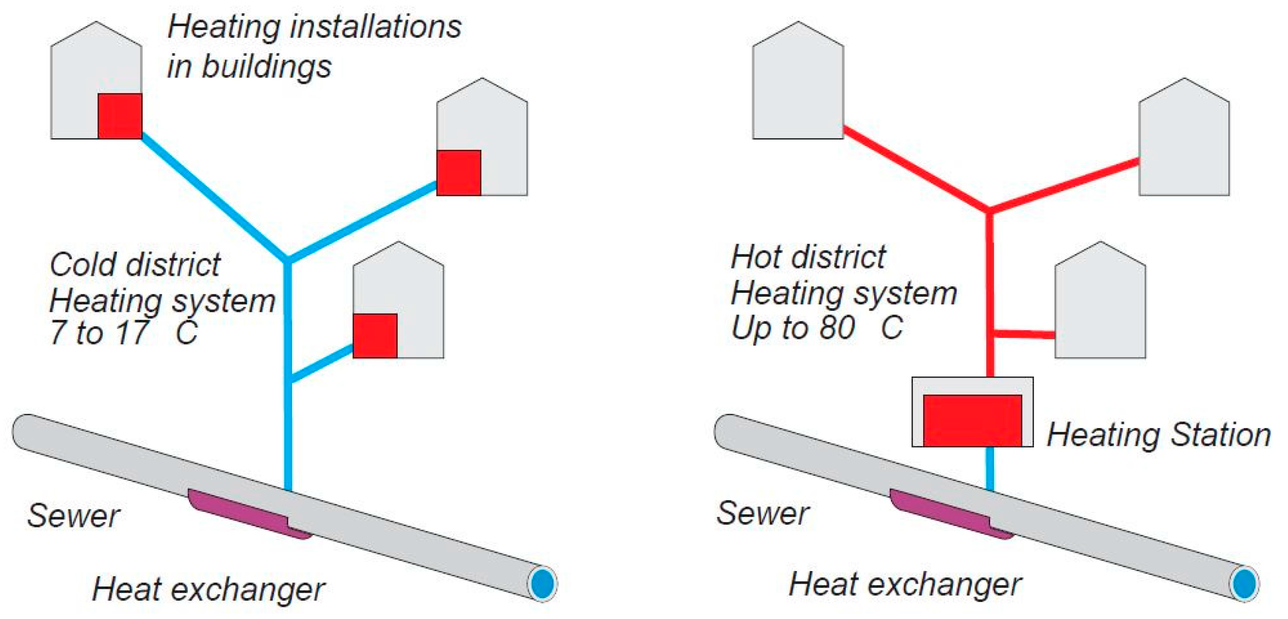
| At a larger district level, where the GW enters the sewage lines | 15–30 °C | 10,000 > L/min depending on the location and pipe diameter | Both in-line (plate HEs) and out-line (HEs & HPs) using additional pumps | A higher content of contaminants—40–50% of the original energy content |
| At a waste water treatment plant (WWTP), along with the purification process | 10–20 °C | 10,000 < L/min | HPs to transport the large quantities over distance | 10–30% depending on before/ after purification |
| Type | Manufacturers | Cost | Images |
|---|---|---|---|
| Falling Film/Gravity |
| £300–925 |  |
| Concentric pipes |
| £250–600 |  |
| Plate |
| £300–2000 | 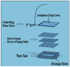 |
| Shell and tube tank |
| £1150 |  |
| In-line sewage HE (plate type) |
| £750–1700 per kW | 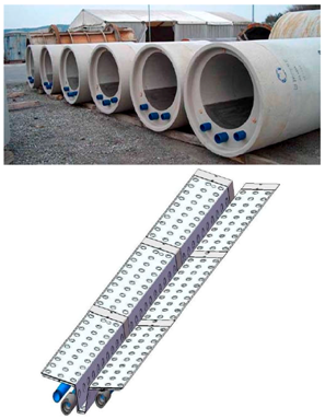 |
| Off-line HE |
| £5000< |  |
| S.No | Issues | Constraints Highlighted in the Study |
|---|---|---|
| 1. | Biological impurities & fouling. | The GW has many biological impurities and detergents within it. When this water is in contact with a heat exchanging device, film deposits and fouling on the exchange surface are vulnerable. In the long term, this greatly effects the performance of the harnessing technology and requires higher efforts in maintenance. It is simply not worth it especially in small scale applications. |
| 2. | Low pressure of incoming water streams. | The mains inflow cold water in the UK has typical pressures of about 1 bar with a minimum legal requirement of 0.7 bars. Transferring heat, to this, with flow restrictions in the exchanging surface, would lower the pressure, which is bearable to an extent. In the case of GW, the pressure is even lower with water flowing only due to the vertical pull of gravity, which makes the cushion for having pressure losses minimal. Unless additional pumps are used, which increases energy requirements and costs, going against the overall objective of passive heating mechanisms. |
| 3. | High flow rates. | From the last two points, it is obvious that constrictions in the flow of GW, to extract the heat, are unacceptable. However, at the same time, the flowrate of this water is in the range of 6–15 L/min, depending on the application. This makes the extraction of heat difficult in a short amount of time without a fast heat transferring mechanism. |
| 4. | Intermittent supply and demand patterns. | The flow of the GW is intermittent, with a high flow rate within a short interval of time. The usage pattern is also unpredictable depending on the user. This calls for a passive storage mechanism to decouple demand and supply with the need for a fast heat conducting mechanism. |
| 5. | Space constraints. | Space is always a constraint especially in non-industrial setups. The installation space within appliances or even within the sewage system is limited. Heat can either be extracted at the exit of appliances or at the beginning of the main sewage pipe of a household. A compact, low cost, maintenance free extractor is required. |
| 6. | Separation of GW and BW. | Usually in most buildings, there is a common stack without the separation of GW and BW. This limits the harnessing to be carried out before the GW enters the stack. |
| Conventional Harnessing | Proposed Schema |
|---|---|
| Usually single-appliance based or single building based | Flexibility to be utilized with single appliances, single buildings or at a district level |
| Limited exergetic efficiencies | Higher heat extraction potential to enhance exergetic efficiency |
| Mechanical moving parts and high maintenance costs | Simple parts with higher reliability |
| Cost intensive | Mediocre costs reducing with research advancements in the future |
| Supply and demand coupled together since hot water must be produced when GW flows | Decoupled demand and supply, where the heat of the GW can be stored without the need to immediately transfer it |
| Limited demand side management and optimization techniques | Stored energy could be utilized by efficiently managing all resources since the constraint of time is removed |
| Heat recovery and heat storage done separately | Integrated heat recovery and storage in a single system |
| Usually only applicable to sensible heat storage on a small-scale level | Usage of high density latent heat storage, so heat could be transferred to any secondary source at any level making the versatility of usage applications larger |
| Only linked to a single building | Has the potential to be dynamically utilized on a large scale, with a smart controller Buildings could be utilized as a decentralized heat source on a district level conforming with the overall concept of smart energy grids |
| Must be custom designed based on application and topography | Applicable to a range of conditions only with minor changes |
| Application | Reference | Overview | Results/Conclusions |
|---|---|---|---|
| Waste industrial heat at 500 K. | [66,67] | An experimental study was conducted to mimic the actual circumstances, on a large scale, where PCMs were used to recover and transfer latent heat from industrial waste at a temperature of over 500 K. Experiments were conducted for encapsulated PCMs and the packed bed configurations. The characteristics of six different PCMs were ranked according to different thermodynamic, chemical and economic considerations. | The metallic encapsulated design showed better transfer rates. While con-current flow compared with counter flow strategies provided better heat transfer rates. |
| Waste heat from a steel plant to a chemical plant. | [68] | In this theoretical study, the feasibility of using PCMs to transfer heat, at over 300 °C, from one industrial setup to another is analyzed. NaOH is used as the PCM, having a melting temperature of 320 °C. The feasibility analysis is done in terms of energy savings, exergy potential improvements, carbon emissions and economic aspects. Theoretically transferring 8.15 GJ of heat was analyzed, with different parameters and characteristics in comparison with conventional sensible storage heat mechanisms. | Compared to a sensible storage mechanism, about 2.76 times more energy is transferred. Comparatively this setup consumes only 8.6% of the energy, has 38% more exergy efficiency and 18% more carbon savings than a conventional system. |
| Recovering waste heat in dishwashers/washing machines. | [69,70] | In this experimental study, four different PCMs were used to preheat the cold water in a second cycle from the waste heat of the first cycle, in a washing machine and dishwashers. Thermal cycling was also investigated by testing the PCM in 1000 thermal cycles. | A temperature increase of 13.4 °C was achieved in the second cycle. The PCMs remained chemically stable with only a loss of 10% of the latent heat. |
| Simple PCM heat exchanger. | [71] | In this published patent, a coaxial heat exchanger with two cylindrical pipes is designed. The inner cylinder stores heat from a fluid to the PCM while the second cylinder contains the fluid, to which it must be transferred. | Although the heat exchanger can be used in a wide range of applications, the patent intends to use it for waste heat recovery applications. |
| Waste heat storage from cooking stoves. | [72] | This is a simulative study, in which a design is proposed for commercial stove tops to limit convective heat losses from the top. After storage of this otherwise wasted heat, the PCM can be discharged in other useful applications. The stove top is numerically analyzed to view the temperature and thermodynamic performance. | It is only feasible to use this stove top in commercial applications, since efficiencies are too low in domestic conditions. |
| Exhaust heat from an air-conditioning unit. | [73,74,75,76] | In this study, a PCM is used to capture the waste heat ejected from the condenser of an air conditioning unit and heat incoming cold water. Analysis is focused on using the finned tube heat exchanger to capture the waste heat, with different variations. An experimental test rig, with the different configurations investigates this phenomenon. | Results show that a Spiral Finned Double Tube exchanger in vertical position is best suited for this application. The PCM also has graphite embedded in it to enhance conductivity. COP of the air conditioner was enhanced as well. |
| Waste heat recovery from engine exhaust. | [77,78,79] | About 30% of the heat of combustion leaves a diesel engine via the exhaust. In this experimental study, a PCM heat exchanger integrated with a storage tank is used to extract this heat, with different loading conditions. A similar analysis is done for normal IC engines varying the parameters and conditions, in experimental and numerical studies. | About 10–15% of the heat of combustion is recovered, which is about 7% of the fuel energy, corresponding to about 86.45 kg/KJ of energy. Results show that the flow rate of the exhaust gas is a bottleneck yet to be addressed effectively. |
| Automobile coolant waste heat recovery. | [80] | In this experimental study, two important criteria; the heat transfer rate and time required to store energy from an engine coolant to a fin and tube heat exchanger filled with a PCM was analyzed. The recovered heat by this PCM, could be used to heat the engine during start-up. A PCM with a melting temperature of about 100 °C was selected. | The warm-up time of an engine was decreased by 34% using 4.2 kg of PCM by extracting heat from approximately 5.5 L of coolant. |
| Waste heat from a fuel cell. | [81] | A PCM was experimentally tested and analyzed for use in this application to harness waste heat from a fuel cell, normally between 60–100 °C. The addition of additives is also analyzed to enhance the thermal and chemical properties of the PCM. The effects of 1000 cycles on the long-term stability was also analyzed. | Magnesium nitrate Hexahydrate was analyzed for this specific application with several additives. Such additives, made the PCM extremely suitable to the application having all the desired properties. |
| Waste heat recovery from industrial air compressors. | [82] | The performance of a small-scale plate heat exchanging evaporator (2–5 kW) to recover waste heat from a compressor, using an organic PCM was experimentally tested. Using a numerical method, multiple conditions were simulated and analyzed for this specific application. The PCM is part of an organic Rankine cycle to eventually convert this heat to electrical energy. | Although it is feasible, proper control strategies varying with external conditions must be ensured, for smooth operation due to the unstable thermodynamics of the PCM. |
| Improving efficiency in household refrigerators. | [83] | A PCM slab is experimentally added on the outside surface of the evaporator of a common household refrigerator. The theory is that the PCM is capable of extracting the waste heat from the refrigerator and sharing the load with the evaporator. At times of low peak this energy is released back from the PCM, hence ensuring that the loads and performance of the refrigeration cycle are more or less consistent. | Such enhancement techniques by the addition of a PCM, enhances the heat transfer rate allowing a higher evaporating temperature. An increase in 5–15% of the COP is witnessed. |
© 2018 by the authors. Licensee MDPI, Basel, Switzerland. This article is an open access article distributed under the terms and conditions of the Creative Commons Attribution (CC BY) license (http://creativecommons.org/licenses/by/4.0/).
Share and Cite
Mazhar, A.R.; Liu, S.; Shukla, A. A Key Review of Non-Industrial Greywater Heat Harnessing. Energies 2018, 11, 386. https://doi.org/10.3390/en11020386
Mazhar AR, Liu S, Shukla A. A Key Review of Non-Industrial Greywater Heat Harnessing. Energies. 2018; 11(2):386. https://doi.org/10.3390/en11020386
Chicago/Turabian StyleMazhar, Abdur Rehman, Shuli Liu, and Ashish Shukla. 2018. "A Key Review of Non-Industrial Greywater Heat Harnessing" Energies 11, no. 2: 386. https://doi.org/10.3390/en11020386
APA StyleMazhar, A. R., Liu, S., & Shukla, A. (2018). A Key Review of Non-Industrial Greywater Heat Harnessing. Energies, 11(2), 386. https://doi.org/10.3390/en11020386