A Structural Design Concept for a Multi-Shell Blended Wing Body with Laminar Flow Control

 , and
, and
Abstract
:1. Introduction
2. Fuselage Segment Model
2.1. Structural Components
2.2. Material
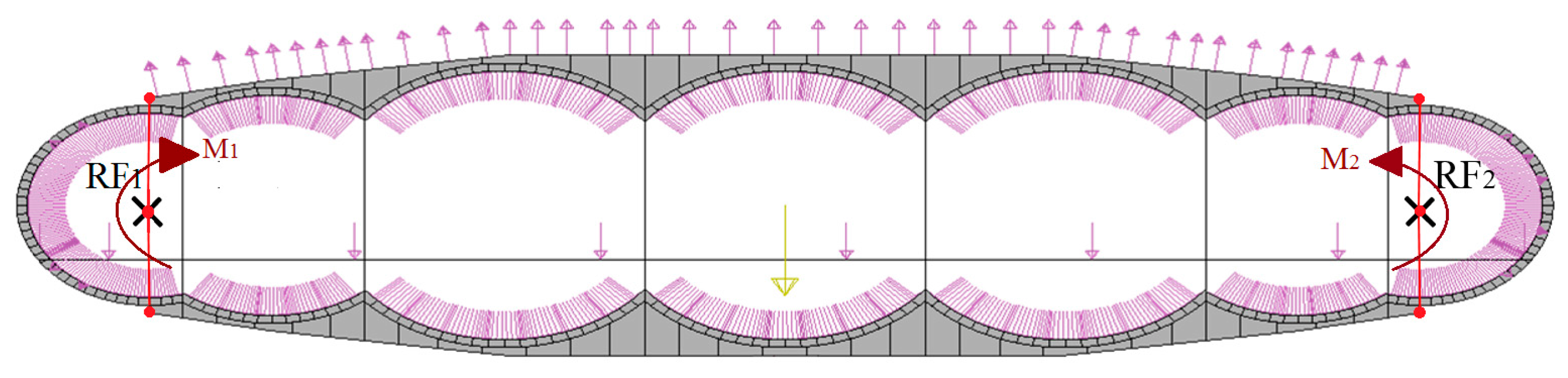
2.3. Loads and Boundary Conditions for the Static Analysis
2.4. Static Failure Criterion
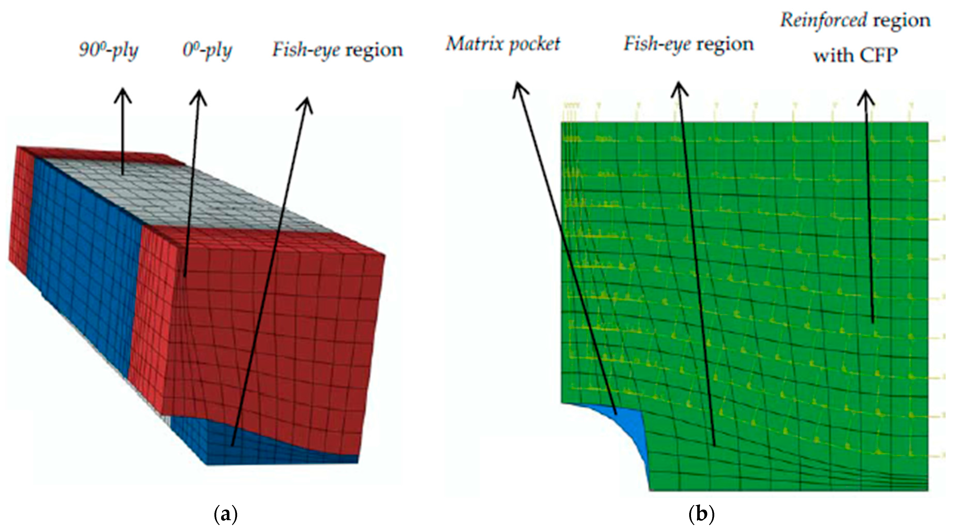
3. Micro Model for the Perforated Outer Skin
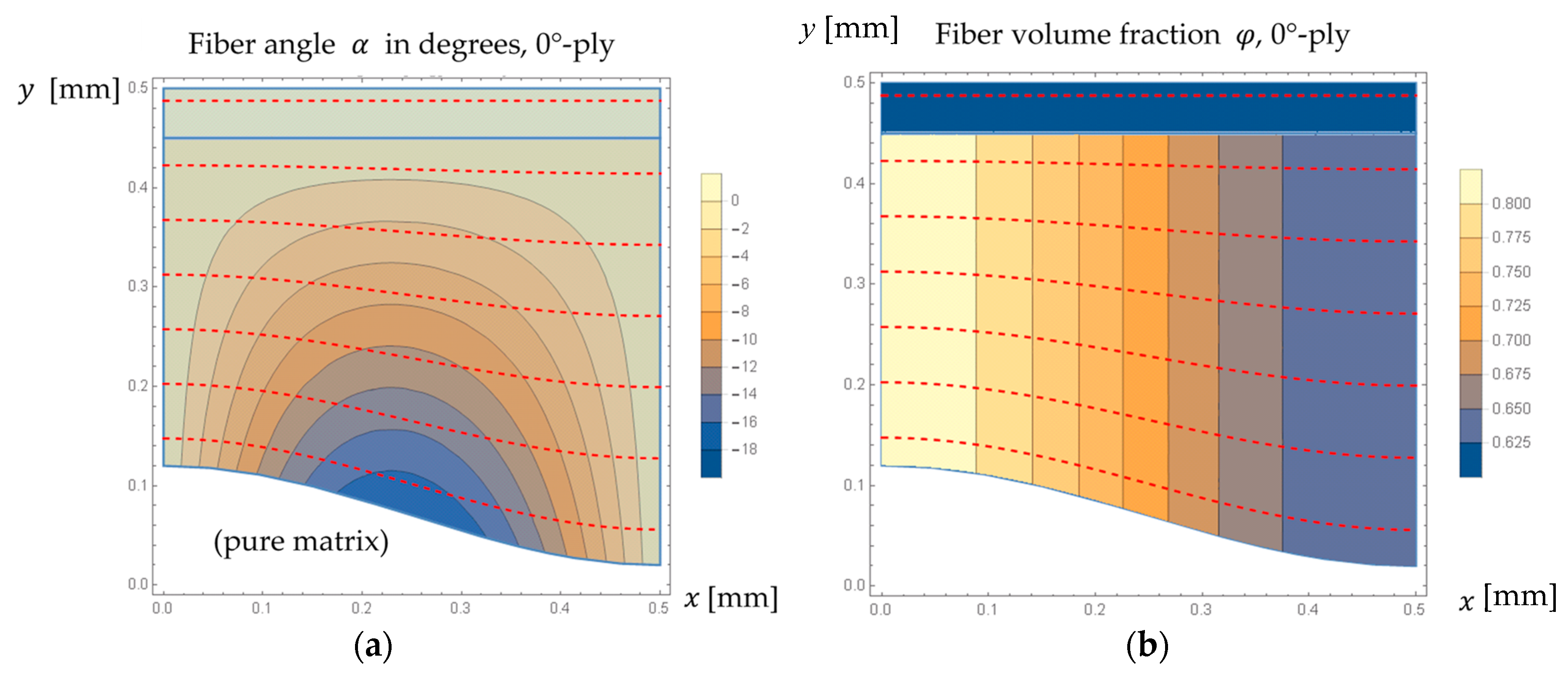
3.1. Fiber Placement
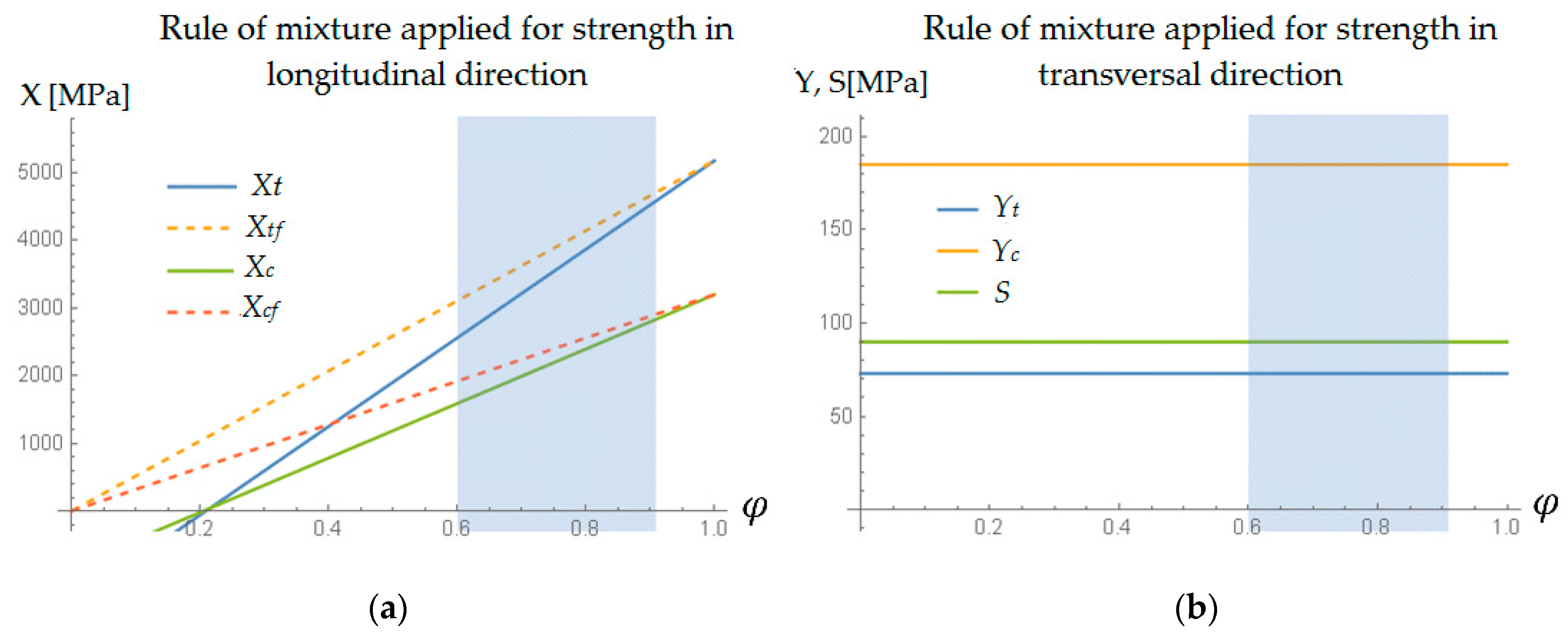
3.2. Variation in Material Properties
3.3. Simplified Layup and Consequent Extensional Stiffness Matrix
4. Static Analysis
5. Fatigue Analysis
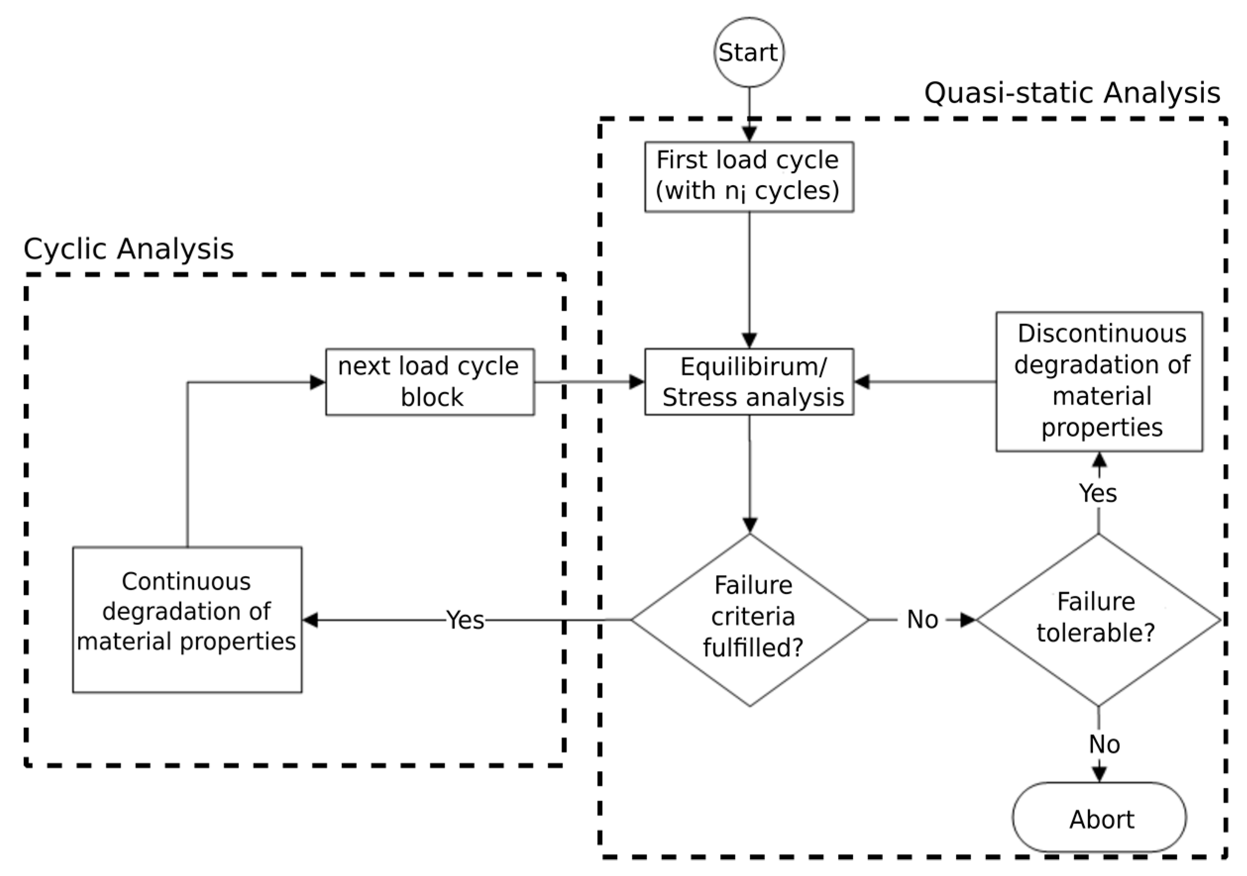
5.1. Fatigue Damage Model (FDM)
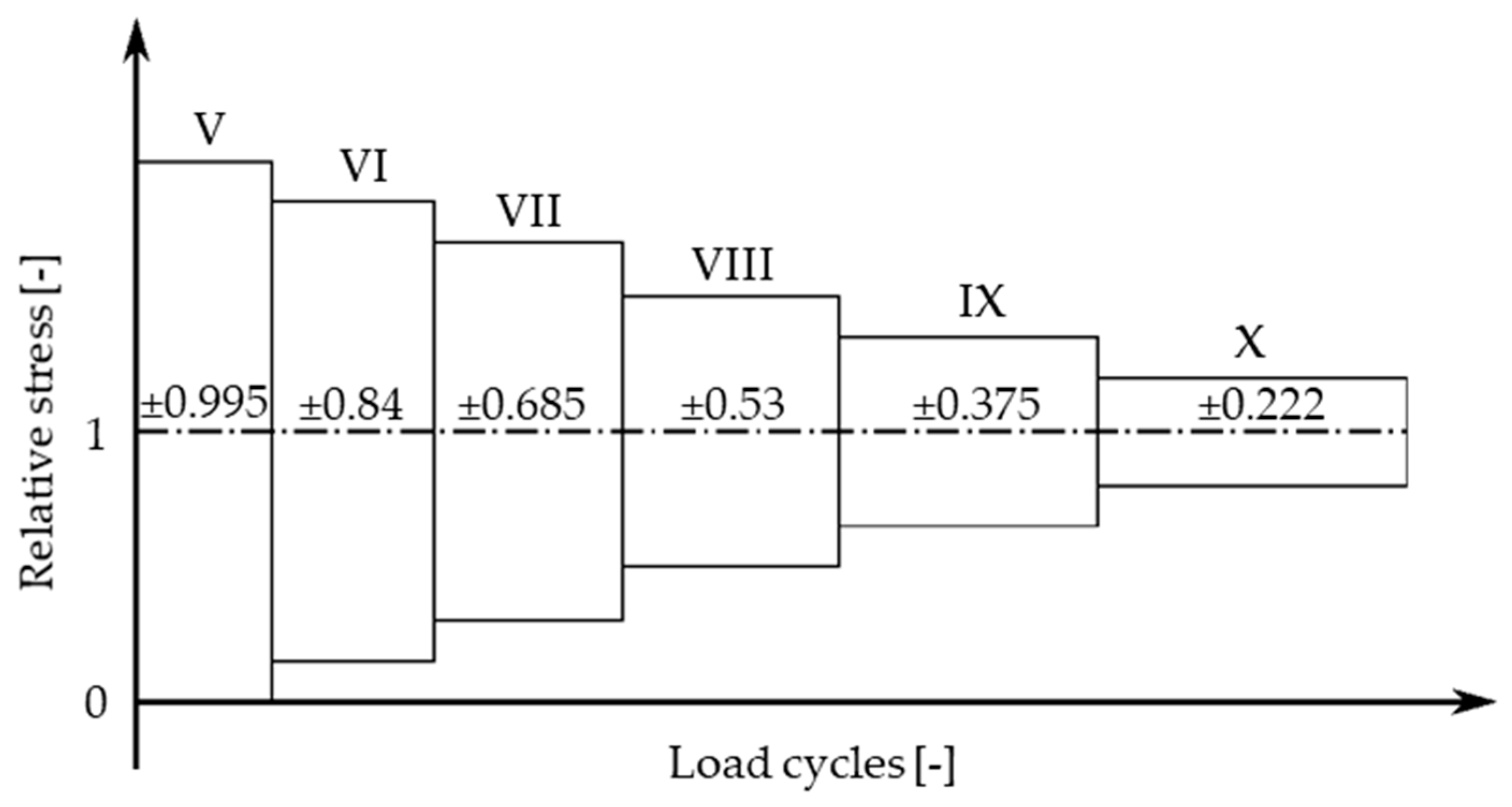
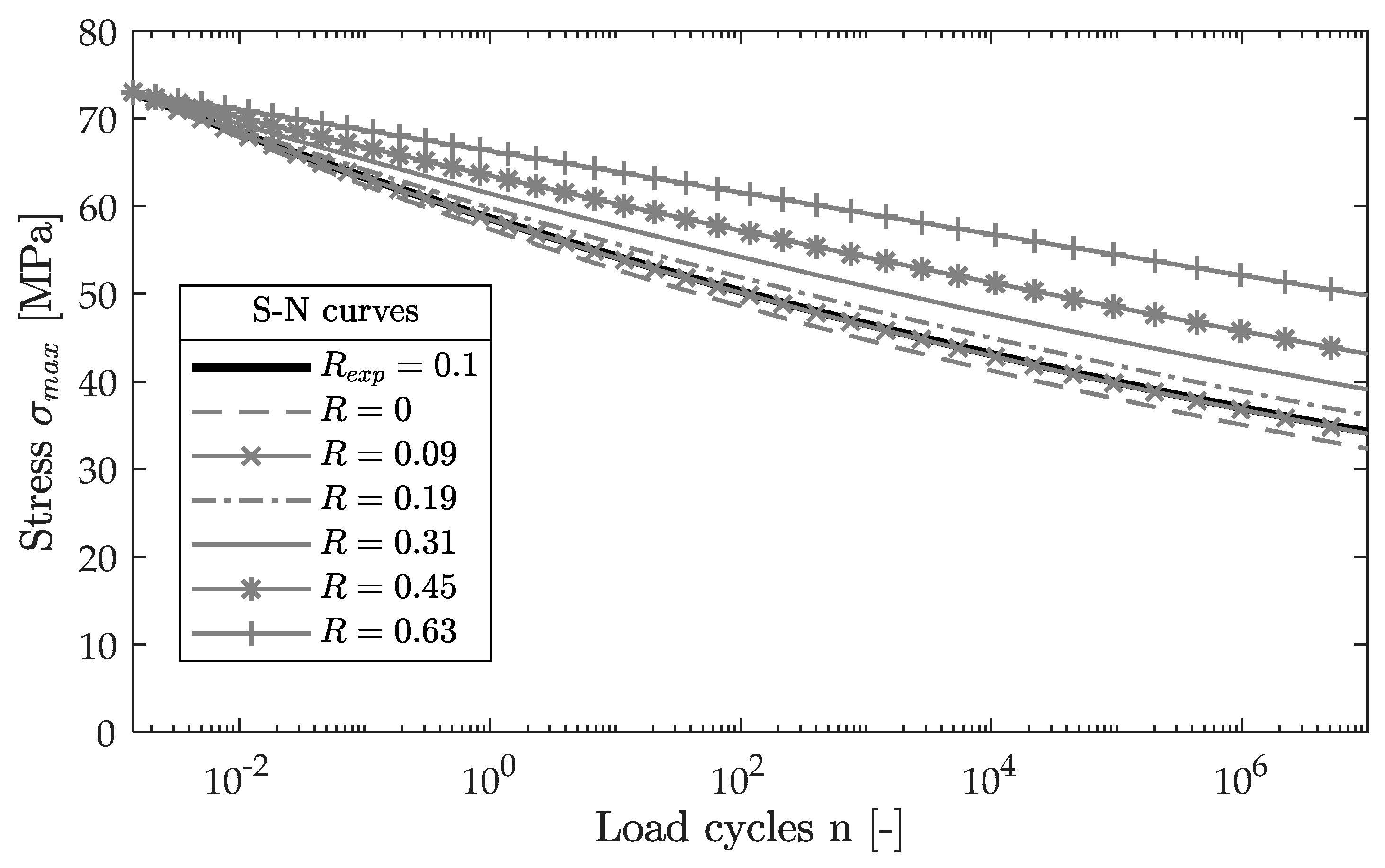
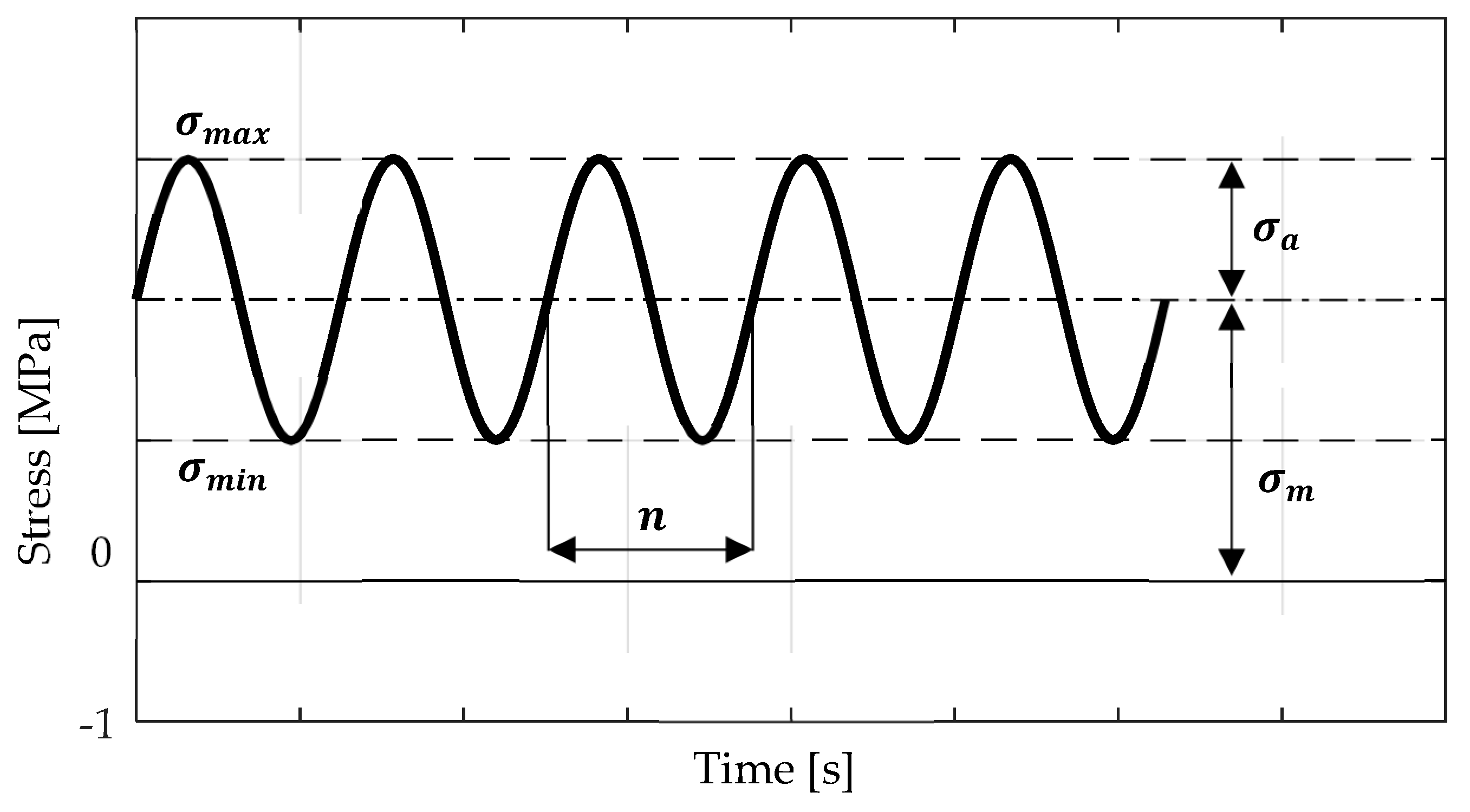
5.2. Load Spectrum and Load Ratios
5.3. Determination of Appropriate S-N Curves
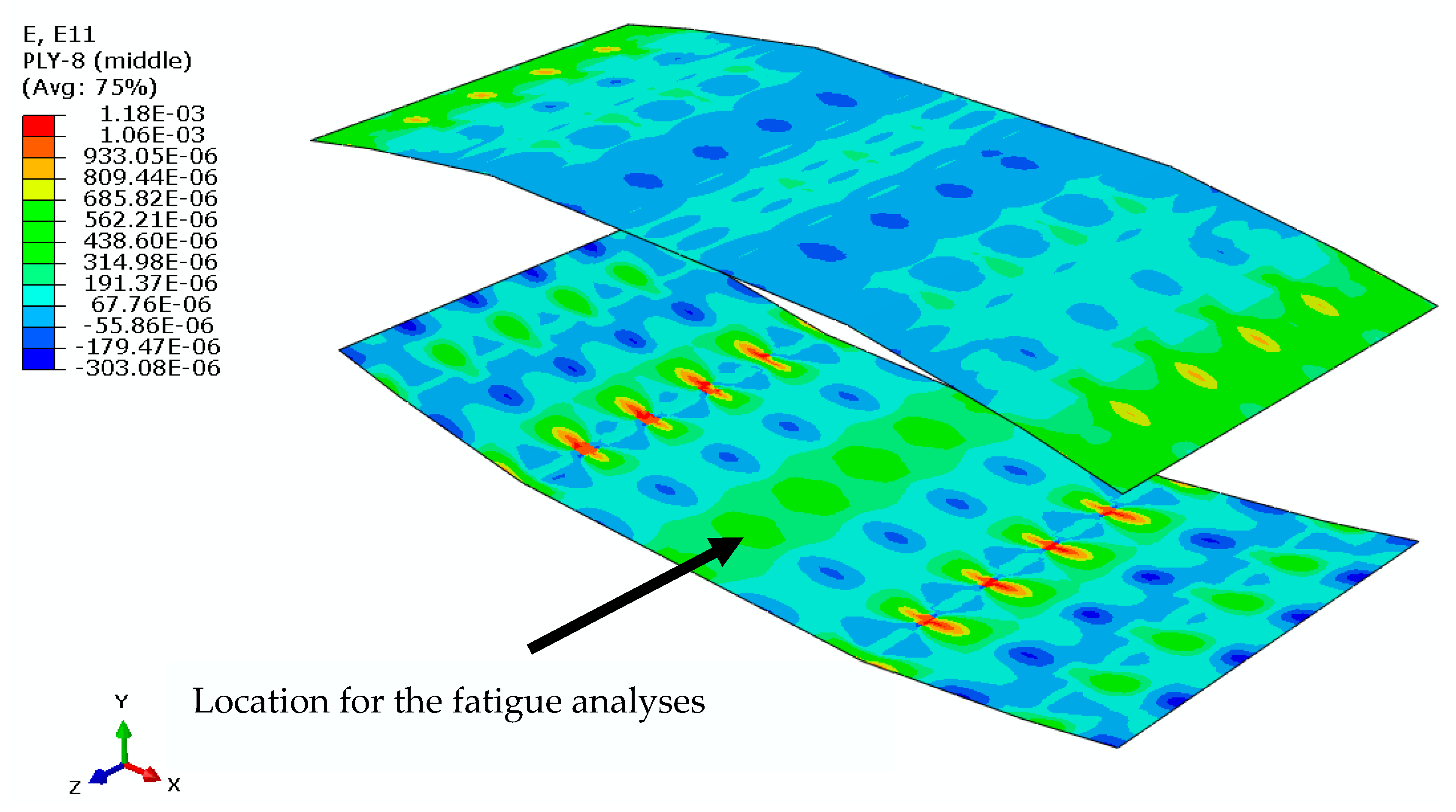
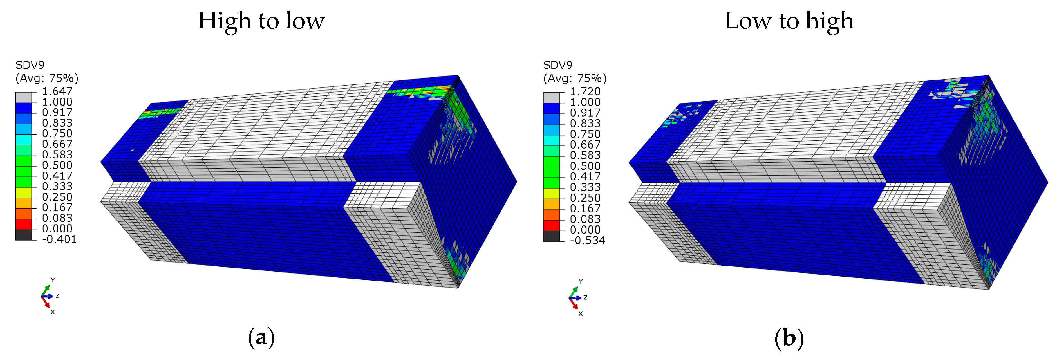
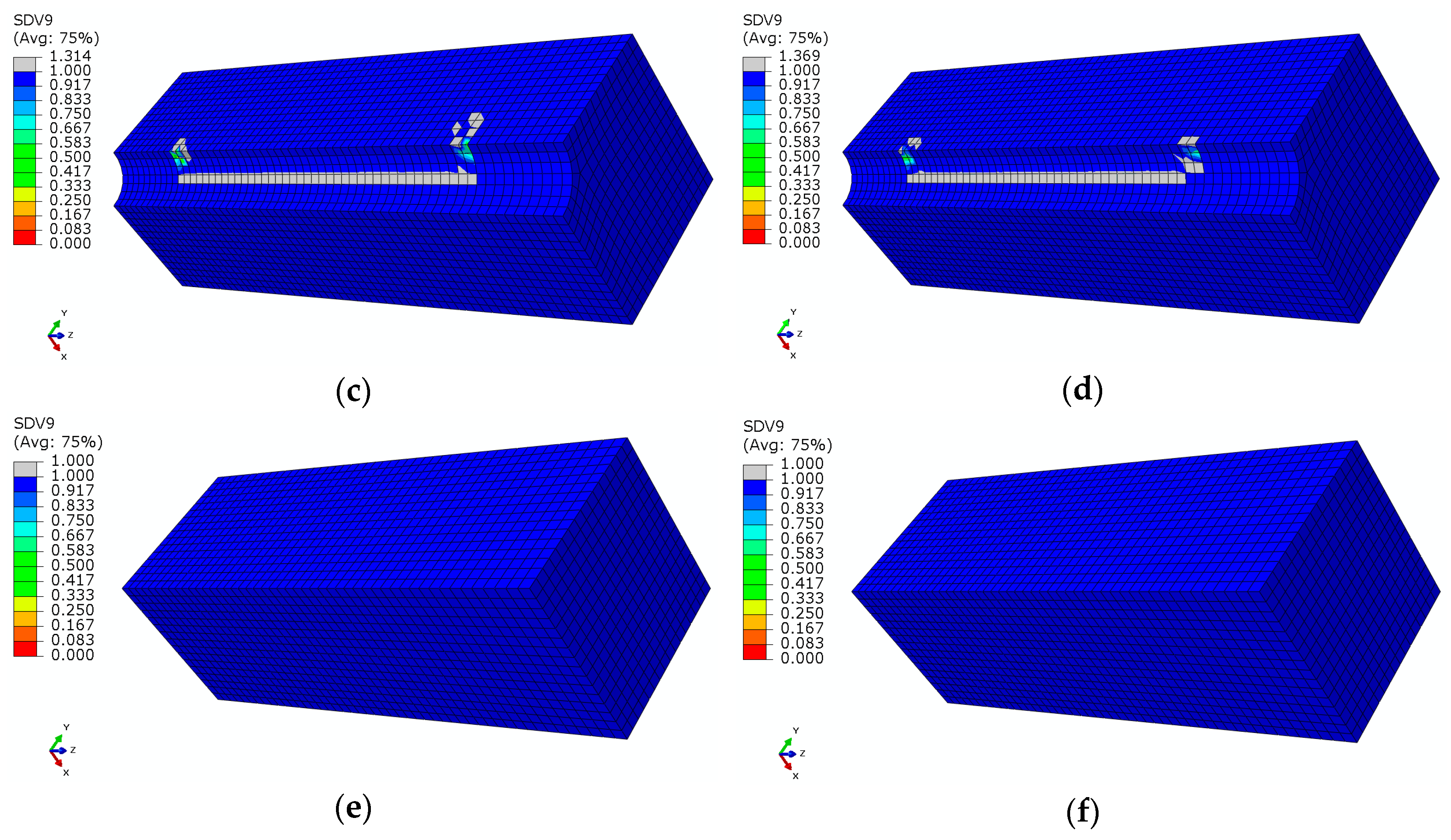
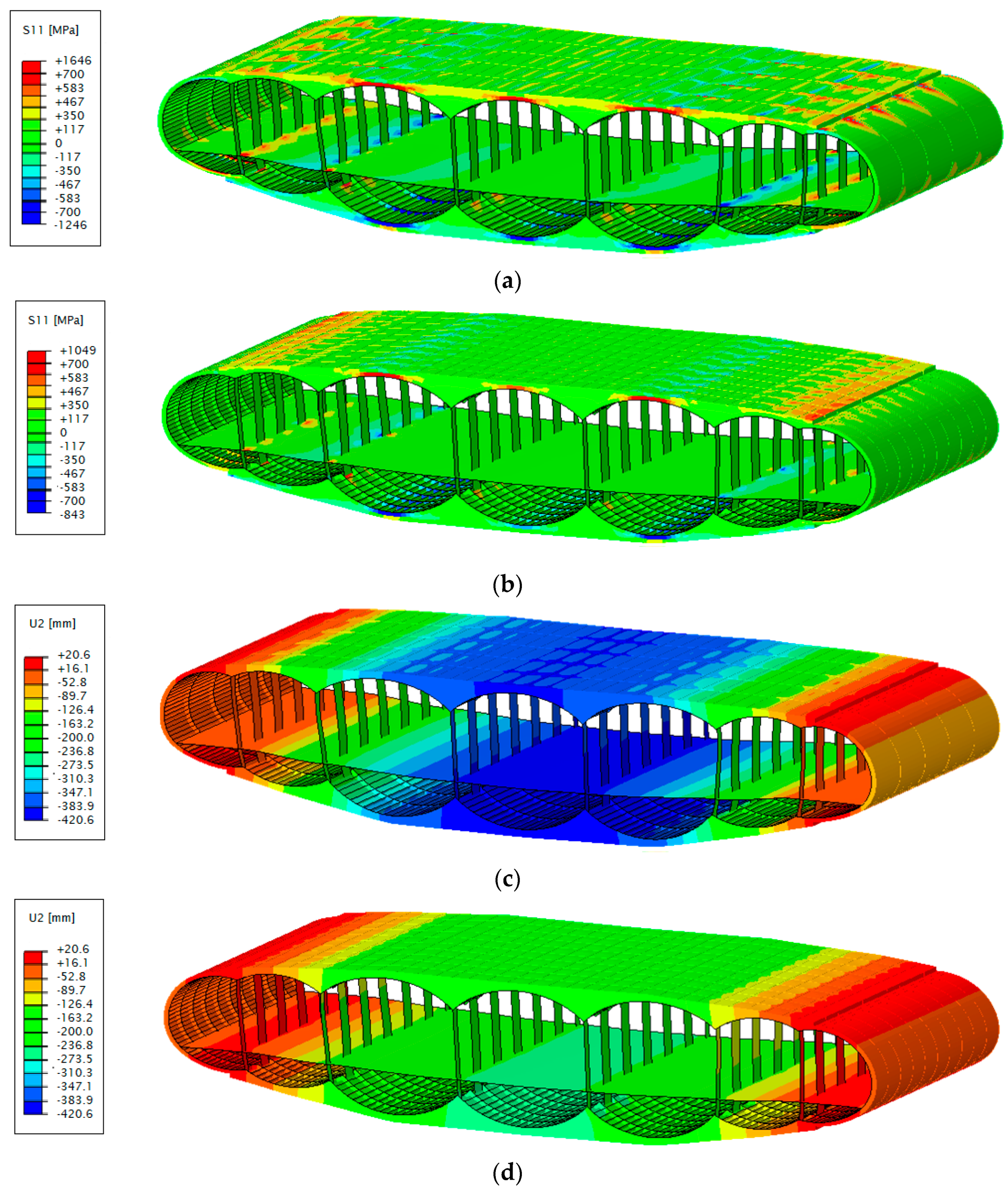
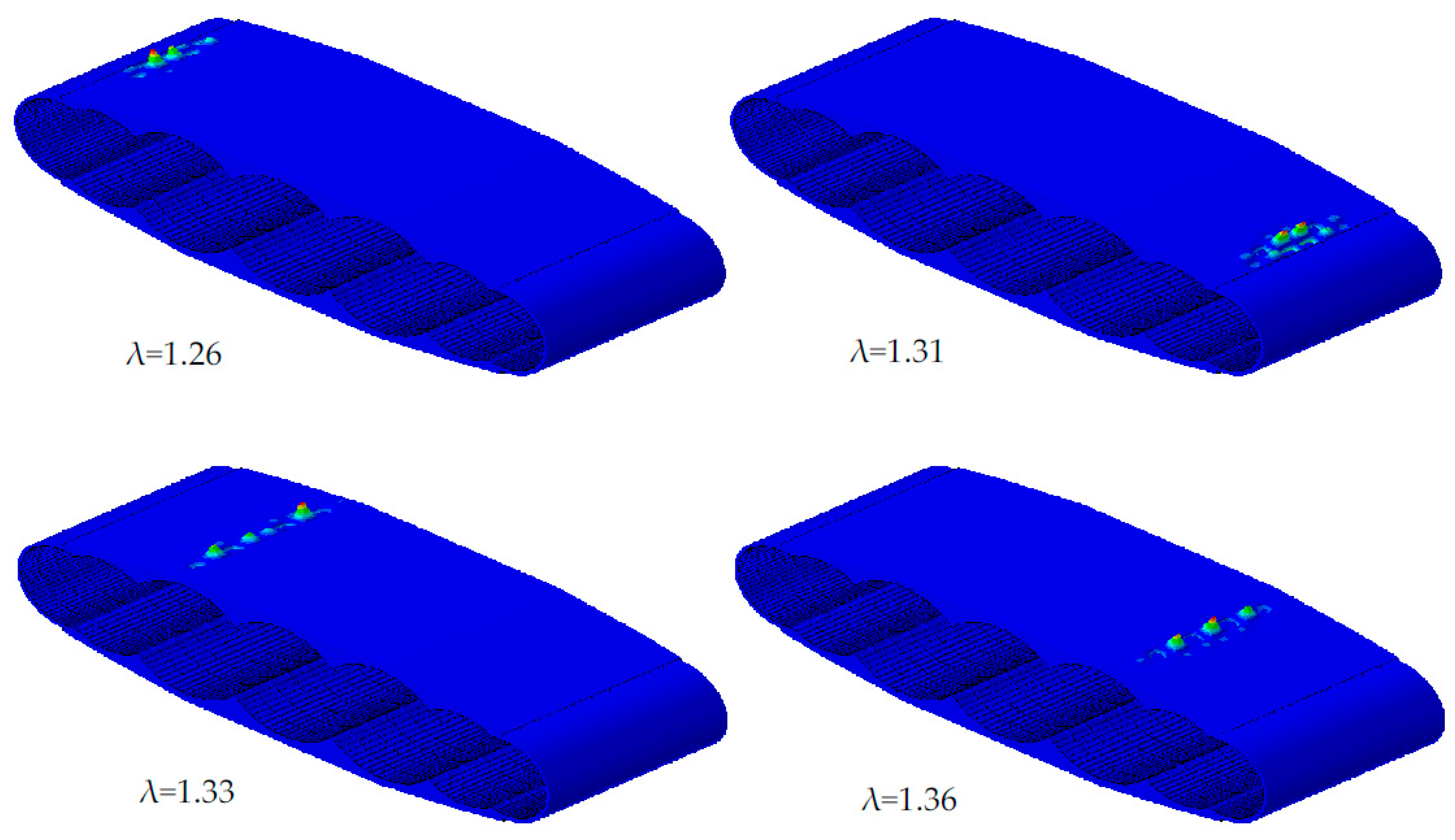
6. Results and Conclusions
Acknowledgments
Author Contributions
Conflicts of Interest
References
- Liebeck, R.; Page, M.; Rawdon, B. Blended-wing-body subsonic commercial transport. In Proceedings of the 36th AIAA Aerospace Sciences Meeting and Exhibit, Reno, NV, USA, 12–15 January 1998; American Institute of Aeronautics and Astronautics: Reston, VA, USA, 1998. [Google Scholar]
- Mukhopadhyay, V. Structural concepts study of non-circular fuselage configurations. In Proceedings of the SAE/AIAA World Aviation Congress, Los Angeles, CA, USA, 22–24 October 1996. [Google Scholar]
- Mukhopadhyay, V. Blended wing body (BWB) fuselage structural design for weight reduction. In Proceedings of the 46th AIAA/ASME/ASCE/AHS/ASC Structures, Structural Dynamics and Materials Conference, Austin, TX, USA, 18–21 April 2005; p. 2349. [Google Scholar]
- Mukhopadhyay, V.; Sobieszczanski-Sobieski, J.; Kosaka, I.; Quinn, G.; Charpentier, C. Analysis, Design and Optimization of Non-Cylindrical Fuselage for Blended-Wing-Body (BWB) Vehicle. J. Aircr. 2004, 41, 925–930. [Google Scholar] [CrossRef]
- Joslin, R.D. Aircraft laminar flow control. Annu. Rev. Fluid Mech. 1998, 30, 1–29. [Google Scholar] [CrossRef]
- Collier, F., Jr. An overview of recent subsonic laminar flow control flight experiments. In Proceedings of the 23rd Fluid Dynamics, Orlando, FL, USA, 6–9 July 1993; American Institute of Aeronautics and Astronautics: Reston, VA, USA, 1993. [Google Scholar]
- Beck, N.; Landa, T.; Seitz, A.; Boermans, L.; Liu, Y.; Radespiel, R. Drag Reduction by Laminar Flow Control. Energies 2018, 11, 252. [Google Scholar] [CrossRef]
- Liu, Y.; Elham, A.; Horst, P.; Hepperle, M. Exploring Vehicle Level Benefits of Revolutionary Technology Progress via Aircraft Design and Optimization. Energies 2018, 11, 166. [Google Scholar] [CrossRef]
- Marsh, G. Automating aerospace composite production with fibre placement. Reinf. Plast. 2011, 55, 32–37. [Google Scholar] [CrossRef]
- Schuetz, D.; Lowak, H.; De Jonge, J.B.; Schijve, J. A Standardized Load Sequence for Flight Simulation Tests on Transport Aircraft Wing Structures; LBF-Report FB-106; NLR-Report TR 73; National Aerospace Laboratory (NLR): Amsterdam, The Netherlands, 1973. [Google Scholar]
- Krueger, H. Ein Physikalisch Basiertes Ermüdungsschädigungsmodell zur Degradations-Berechnung von Faser-Kunststoff-Verbunden. Ph.D. Thesis, Institute of Structural Analysis, University of Hanover, Hannover, Germany, 2012. [Google Scholar]
- Krüger, H.; Rolfes, R. A physically based fatigue damage model for fibre-reinforced plastics under plane loading. Int. J. Fatigue 2015, 70, 241–251. [Google Scholar] [CrossRef]
- Der Voet, Z.V.; Geuskens, F.J.M.M.; Ahmed, T.J.; Van Eyben, B.N.; Beukers, A. Configuration of the Multibubble Pressure Cabin in Blended Wing Body Aircraft. J. Aircr. 2012, 49, 991–1007. [Google Scholar] [CrossRef]
- Geuskens, F.; Bergsma, O.K.; Koussios, S.; Beukers, A. Pressure Vessels & Pressure Cabins for Blended Wing Bodies. In Proceedings of the ICCM-17 17th International Conference on Composite Materials, Edinburgh, UK, 27–31 July 2009; Volume 27, pp. 1–12. [Google Scholar]
- Hansen, L.U.; Heinze, W.; Horst, P. Blended wing body structures in multidisciplinary pre-design. Struct. Multidiscip. Optim. 2008, 36, 93–106. [Google Scholar] [CrossRef]
- Kaddour, A.; Hinton, M.; Smith, P.; Li, S. Mechanical properties and details of composite laminates for the test cases used in the third world-wide failure exercise. J. Compos. Mater. 2013, 47, 2427–2442. [Google Scholar] [CrossRef]
- Hexcel Corporation. HexWeb® CR III Corrosion Resistant Specification Grade Aluminum Honeycomb; Product Data; Hexcel Corporation: Stamford, CT, USA, 2017. [Google Scholar]
- Hibbitt, K.; Sorensen. ABAQUS/Standard User’s Manual; Hibbitt; Karlsson & Sorensen: Johnston, RI, USA, 2001. [Google Scholar]
- Hashin, Z. Failure Criteria for Unidirectional Fiber Composites. J. Appl. Mech. ASME 1980, 47, 329–334. [Google Scholar] [CrossRef]
- Hashin, Z.; Rotem, A. A fatigue failure criterion for fiber reinforced materials. J. Compos. Mater. 1973, 7, 448–464. [Google Scholar] [CrossRef]
- Koricho, E.G.; Khomenko, A.; Fristedt, T.; Haq, M. Innovative tailored fibre placement technique for enhancd damage resistance in notched composites. Compos. Struct. 2015, 378–385. [Google Scholar] [CrossRef]
- Mattheij, P.; Gliesche, K.; Feltin, D. Tailored fibre placement—Mechanical properties and applications. J. Reinf. Plast. Compos. 1998, 17, 774–786. [Google Scholar] [CrossRef]
- Chamis, C.C. Mechanics of Composite Materials: Past, Present, and Future. J. Compos. Technol. Res. 1989, 11, 3–14. [Google Scholar]
- Dvorak, G.J. Elementary Concepts and Tools. In Micromechanics of Composite Materials; Springer: Berlin, Germany, 2013; pp. 35–77. [Google Scholar]
- Degrieck, J.; Van Paepegem, W. Fatigue damage modeling of fibre-reinforced composite materials. Appl. Mech. Rev. 2001, 54, 279–300. [Google Scholar] [CrossRef]
- Madhusoodanan, H.; Jansen, E.; Rolfes, R. Simulation of damage behavior in GFRPs in the very high cycle regime. In Proceedings of the VHCF7—Seventh International Conference on Very High Cycle Fatigue, Dresden, Germany, 3–5 July 2017. [Google Scholar]
- Reifsnider, K.L.; Jamison, R. Fracture of fatigue-loaded composite laminates. Int. J. Fatigue 1982, 4, 187–197. [Google Scholar] [CrossRef]
- Puck, A. Festigkeitsanalyse von Faser-Matrix-Laminaten: Modelle für Die Praxis; Hanser: Munich, Germany, 1996. [Google Scholar]
- Knops, M. Analysis of Failure in Fiber Polymer Laminates: The Theory of Alfred Puck; Springer Science & Business Media: Berlin, Germany, 2008. [Google Scholar]
- Pfanner, D. Zur Degradation von Stahlbetonbauteilen unter Ermüdungsbeanspruchung; VDI-Verlag: Düsseldorf, Germany, 2002. [Google Scholar]
- Nijssen, R.P.L. Optidat-Database Reference Document—The Knowledge Centre Wind Turbine Materials and Constructions; Delft University of Technology: Wieringerwerf, Germany, 2005. [Google Scholar]
- Schijve, J. The Accumulation of Fatigue Damage in Aircraft Materials and Structures; AGARDograph No. 157; National Aerospace Laboratory NLR: Amsterdam, The Netherlands, 1972. [Google Scholar]
- Schijve, J. Fatigue damage in aircraft structure, not wanted, but tolerated. Int. J. Fatigue 2009, 31, 998–1011. [Google Scholar] [CrossRef]
- Wanhill, R.J.H. Flight Simulation Fatigue Crack Growth Guidelines; No. 545; National Aerospace Laboratory NLR: Amsterdam, The Netherlands, 2001. [Google Scholar]
- El Kadi, H.; Ellyin, F. Effect of stress ratio on the fatigue of unidirectional glass fibre/epoxy composite laminae. Composites 1994, 25, 917–924. [Google Scholar] [CrossRef]
- Kawai, M. A phenomenological model for off-axis fatigue behavior of unidirectional polymer matrix composites under different stress ratios. Compos. Part A Appl. Sci. Manuf. 2004, 35, 955–963. [Google Scholar] [CrossRef]
- Goodman, J. Mechanics Applied to Engineering, 4th and enl. ed.; Longmans, Green and Co.: London, UK, 1904. [Google Scholar]
- Hussain, M.S.; Anilchandra, A.R.; Jagannathan, N.; Manjunatha, C.M. Fatigue life prediction of a unidirectional carbon fiber composite under off-axis spectrum loads using 3D constant life diagram. Mater. Perform. Charact. 2016, 5, 132–147. [Google Scholar] [CrossRef]
- Buch, A. Fatigue Strength Calculation; Trans Tech Publ: Zürich, Switzerland, 1988. [Google Scholar]
- Cuntze, R. Progress reached?—Lifetime Prediction for UD-materials by using S-N curves, Kawai’s Modified Fatigue Strength Ratio and Novel Haigh Diagrams. In Proceedings of the Simulation von Composites—Bereit für Industrie 4.0? Hamburg, Germany, 26–27 October 2016. [Google Scholar]


| Long Range Blended Wing Body (BWB) Aircraft | |
|---|---|
| Passengers | 300–400 |
| Maximum takeoff weight MTOW (t) | 132 |
| Operating empty weight OWE (t) | 78 |
| Outer wing area (m2) | 133 |
| Outer wingspan (m) | 53.3 |
| Energy conversion | Intercooled recuperated gas turbine, synchronized electric motor |
| Energy storage | Synthetic fuel |
| Type | Laminate Configuration/Thickness [mm] | Total Thickness [mm] |
|---|---|---|
| Global fuselage laminate | [45/0/-45/90/45/90/-45/90]s/(0.125) | 2 |
| Simplified micro model | ||
| Without perforation | [0/90]s/(0.27/0.52) | 1.58 |
| With perforation, no CFP | [0/90]s/(0.29/0.61) | 1.81 |
| With perforations, with CFP | [0/90]s/(0.27/0.57) | 1.68 |
| Numerical Results | Conf. 1 | Conf. 2 |
|---|---|---|
| Max. stress (MPa) | 1646 | 1049 |
| Max. deflection (mm) | 421 | 257 |
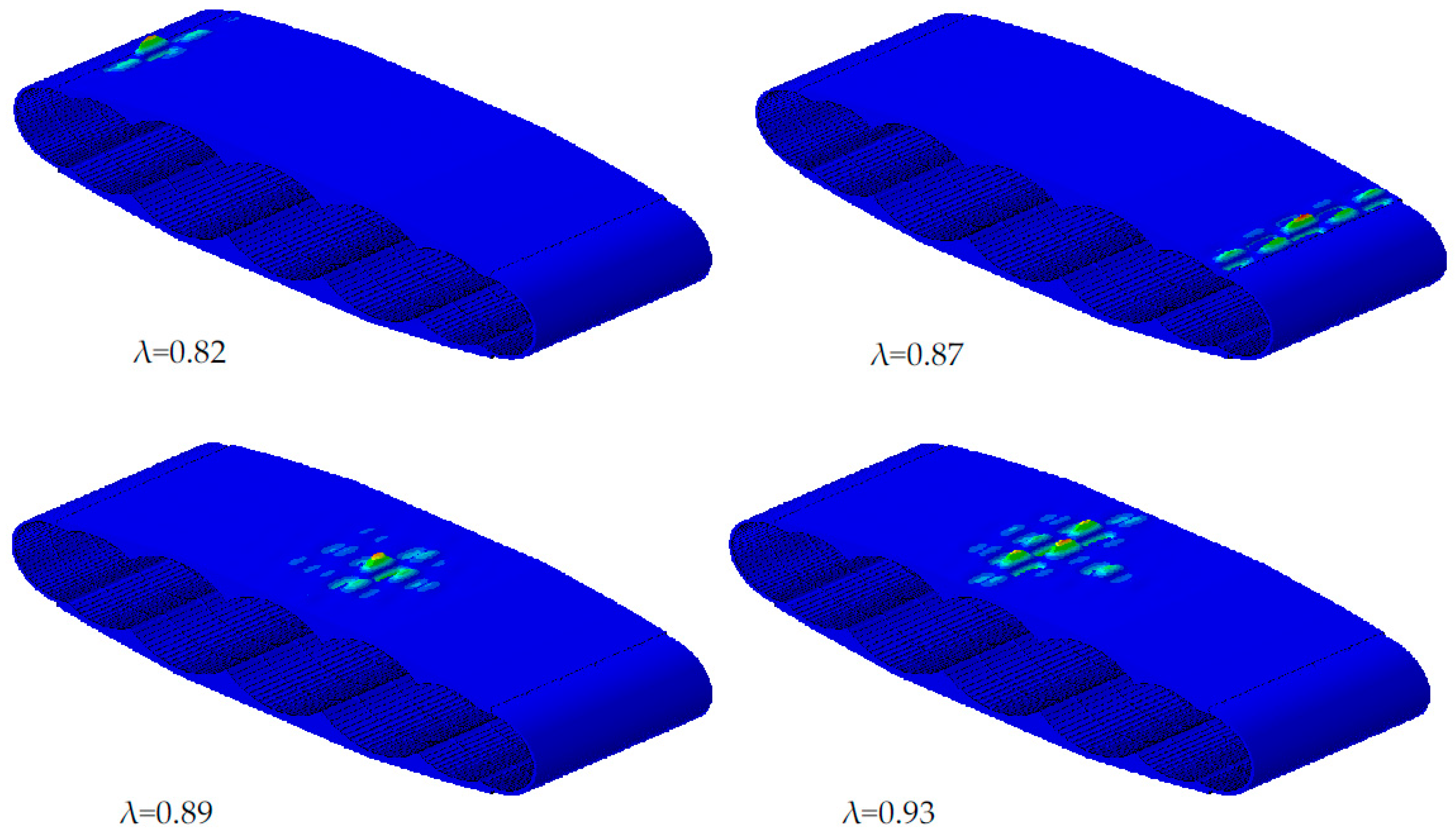
| First four eigenvalues λ | 0.82, 0.87, 0.89, 0.93 | 1.26, 1.31, 1.33, 1.36 |
| Weight (kg/m2) | 34.63 | 38.68 |
| Weight of damaged elements to segment weight | ||
| Matrix compression | 1.26% | 0.58% |
| Matrix tension | 0.28% | 0.03% |
| Fiber compression | 0.00% | 0.00% |
| Fiber tension | 0.00% | 0.00% |
| Numerical Results | t = 2 mm | t = 3 mm | t = 4 mm | t = 5 mm |
|---|---|---|---|---|
| Max. stress (MPa) | 1811 | 1646 | 1542 | 1472 |
| Max. deflection (mm) | 439 | 421 | 410 | 403 |
| Weight (kg/m2) | 33.91 | 34.63 | 35.35 | 36.06 |
| Weight of damaged elements to segment weight | ||||
| Matrix compression | 1.50% | 1.26% | 1.05% | 0.97% |
| Matrix tension | 0.39% | 0.28% | 0.20% | 0.15% |
| Fiber compression | 0.00% | 0.00% | 0.00% | 0.00% |
| Fiber tension | 0.00% | 0.00% | 0.00% | 0.00% |
| Numerical Results | [45/0/-45/90/ 45/90/-45/90]s | [45/90/-45/0/ 45/0/-45/0]s | [45/-45/45/-45/ 45/-45/45/-45]s |
|---|---|---|---|
| Max. stress (MPa) | 1646 | 1672 | 1663 |
| Max. deflection (mm) | 421 | 423 | 422 |
| Weight (kg/m2) | 34.63 | 34.63 | 34.63 |
| Weight of damaged elements to segment weight | |||
| Matrix compression | 1.26% | 1.27% | 1.27% |
| Matrix tension | 0.28% | 0.29% | 0.28% |
| Fiber compression | 0.00% | 0.00% | 0.00% |
| Fiber tension | 0.00% | 0.00% | 0.00% |
| Load Block | V | VI | VII | VIII | IX | X |
|---|---|---|---|---|---|---|
© 2018 by the authors. Licensee MDPI, Basel, Switzerland. This article is an open access article distributed under the terms and conditions of the Creative Commons Attribution (CC BY) license (http://creativecommons.org/licenses/by/4.0/).
Share and Cite
Bishara, M.; Horst, P.; Madhusoodanan, H.; Brod, M.; Daum, B.; Rolfes, R. A Structural Design Concept for a Multi-Shell Blended Wing Body with Laminar Flow Control. Energies 2018, 11, 383. https://doi.org/10.3390/en11020383
Bishara M, Horst P, Madhusoodanan H, Brod M, Daum B, Rolfes R. A Structural Design Concept for a Multi-Shell Blended Wing Body with Laminar Flow Control. Energies. 2018; 11(2):383. https://doi.org/10.3390/en11020383
Chicago/Turabian StyleBishara, Majeed, Peter Horst, Hinesh Madhusoodanan, Martin Brod, Benedikt Daum, and Raimund Rolfes. 2018. "A Structural Design Concept for a Multi-Shell Blended Wing Body with Laminar Flow Control" Energies 11, no. 2: 383. https://doi.org/10.3390/en11020383
APA StyleBishara, M., Horst, P., Madhusoodanan, H., Brod, M., Daum, B., & Rolfes, R. (2018). A Structural Design Concept for a Multi-Shell Blended Wing Body with Laminar Flow Control. Energies, 11(2), 383. https://doi.org/10.3390/en11020383