Article

Continuous Steering Stability Control Based on an Energy-Saving Torque Distribution Algorithm for a Four in-Wheel-Motor Independent-Drive Electric Vehicle

1
National Engineering Laboratory for Electric Vehicles, Beijing Institute of Technology, Beijing 100081, China
2
Co-Innovation Center of Electric Vehicles in Beijing, Beijing Institute of Technology, Beijing 100081, China
3
BAIC BJEV Inc., Beijing 100021, China
*
Author to whom correspondence should be addressed.
Energies 2018, 11(2), 350; https://doi.org/10.3390/en11020350
Submission received: 14 December 2017 / Revised: 13 January 2018 / Accepted: 25 January 2018 / Published: 2 February 2018
(This article belongs to the Collection Electric and Hybrid Vehicles Collection)

Abstract

:
In this paper, a continuous steering stability controller based on an energy-saving torque distribution algorithm is proposed for a four in-wheel-motor independent-drive electric vehicle (4MIDEV) to improve the energy consumption efficiency while maintaining the stability in steering maneuvers. The controller is designed as a hierarchical structure, including the reference model level, the upper-level controller, and the lower-level controller. The upper-level controller adopts the direct yaw moment control (DYC), which is designed to work continuously during the steering maneuver to better ensure steering stability in extreme situations, rather than working only after the vehicle is judged to be unstable. An adaptive two-hierarchy energy-saving torque distribution algorithm is developed in the lower-level controller with the friction ellipse constraint as a basis for judging whether the algorithm needs to be switched, so as to achieve a more stable and energy-efficient steering operation. The proposed stability controller was validated in a co-simulation of CarSim and Matlab/Simulink. The simulation results under different steering maneuvers indicate that the proposed controller, compared with the conventional servo controller and the ordinary continuous controller, can reduce energy consumption up to 23.68% and improve the vehicle steering stability.

1. Introduction

With the increasing use of electric vehicles (EVs) and the rapid development of motor-integration technology, a four in-wheel-motor independent-drive electric vehicle (4MIDEV) emerged [1,2,3]. The 4MIDEV, unlike the traditional centralized-drive vehicles, is driven by four motors integrated into four wheel hubs. The traction/braking torques of the four driven wheels can be accurately controlled [4,5], which brings more flexibility to the control strategy design. The studies focused on the 4MIDEV platform, especially on its steering-stability controller design, have recently been a very hot research topic [6,7,8].
A great deal of valuable work has been done on the 4MIDEV’s stability controller to improve the steering stability. Zhao et al. [9] investigated a non-linear control allocation scheme based on the predictive control model to improve the steering stability in critical driving conditions. Song et al. [10] developed a hierarchical model-based control methodology consisting of five layers to enhance vehicle stability. Li et al. [11] and He et al. [12] separately studied an optimal torque distribution control strategy for improving the steering stability. Nevertheless, few studies considered energy saving in the design of the steering stability controller, which is an important performance index of the EVs. It is necessary to study a new steering stability controller for the 4MIDEV to improve the energy consumption efficiency while maintaining the stability in steering maneuvers.
In general, the steering stability control of a 4MIDEV is mainly designed as a hierarchical structure, including an upper-level controller with direct yaw moment control (DYC) and a lower-level controller with a torque distribution algorithm [13,14]. In previous studies, the DYC in the upper-level controller usually chooses the sideslip angle and the yaw rate or one of them as the control target [15,16]. Hu et al. [17] investigated a robust yaw moment control for motion stabilization to realize an accurate control of the yaw rate. Ding et al. [18] developed two categories of sliding mode control for DYC to control the yaw rate of the vehicle. However, the integrated control of the yaw rate and the sideslip angle is usually determined after the vehicle is judged to be losing stability. For example, Zhai et al. [4] and Kang et al. [19] separately developed a stability judgment controller and a supervisory controller to determine the control mode, in order to control both yaw rate and sideslip angle after judging whether the vehicle tends to be unstable. This kind of upper-level controller with stability judgement turns out to improve the steering stability to a certain degree, but may cause instability in extreme conditions because of the delayed control [20]. At the same time, compared with a control mode working continuously, a larger torque is also required for this control mode to restrain the tendency of the vehicle to lose its stability, which is not conducive to energy saving. A continuous upper-level controller is needed to better ensure the steering stability and improve the energy consumption efficiency in extreme situations.
In the lower-level controller, the optimal torque distribution algorithm, in general, was proved to be the most effective among the commonly used distribution algorithms, such as average distribution [14], dynamic load distribution [19], and so on. The optimal torque distribution algorithm allocates each wheel torque rationally on the premise of achieving one or more optimal objectives as far as possible, so as to achieve the desired steering control [21,22,23]. Many studies have focused their optimal objectives on steering stability and control error. Zhai et al. [4] chose tire workload usages as the optimal objective for torque distribution, which was proved to improve the steering stability effectively. Yamakawa et al. [22] selected the equivalent longitudinal force control error and the tire workload usages as optimal objectives to ensure the accuracy of the control, and, in [11], Li et al. minimized the control error of the longitudinal force and yaw moment in the allocation algorithm. However, few studies considered energy saving in the optimal distribution algorithm. A proper torque distribution under different conditions can achieve a high energy consumption efficiency and meet the energy saving needs. Moreover, the friction ellipse constraint of the torque distribution was usually oversimplified [4] or overly complex [23], which may bring additional control errors or increase the difficulty and time to solve the distribution problem. There is a need to study an energy-saving torque distribution algorithm in the lower-level controller thus achieving a more energy-efficient torque distribution.
In order to solve the above problems, this paper proposes a continuous steering stability controller based on an energy-saving torque distribution algorithm for the 4MIDEV, including a reference model level, an upper-level controller, and a lower-level controller. The reference model level is used to generate the desired vehicle dynamics parameters such as sideslip angle and yaw rate. The upper-level controller works continuously during the steering maneuvers to achieve the integrated control of the yaw rate and the sideslip angle, rather than performing first a stability judgement. An adaptive two-hierarchy energy-saving torque distribution algorithm is developed in the lower-level controller to realize a multi-objective optimization of energy saving and steering stability. The friction ellipse constraint is introduced as a basis for judging whether the two-hierarchy distribution algorithm needs to be switched.
The organization of this study is as follows: Section 2 illustrates the design of the proposed steering-stability controller; the system modeling and simulation analysis and verification are presented in Section 3; finally, conclusions are provided in Section 4.

2. Design of the Steering Stability Controller Based on an Energy-Saving Torque Distribution Algorithm for 4MIDEV

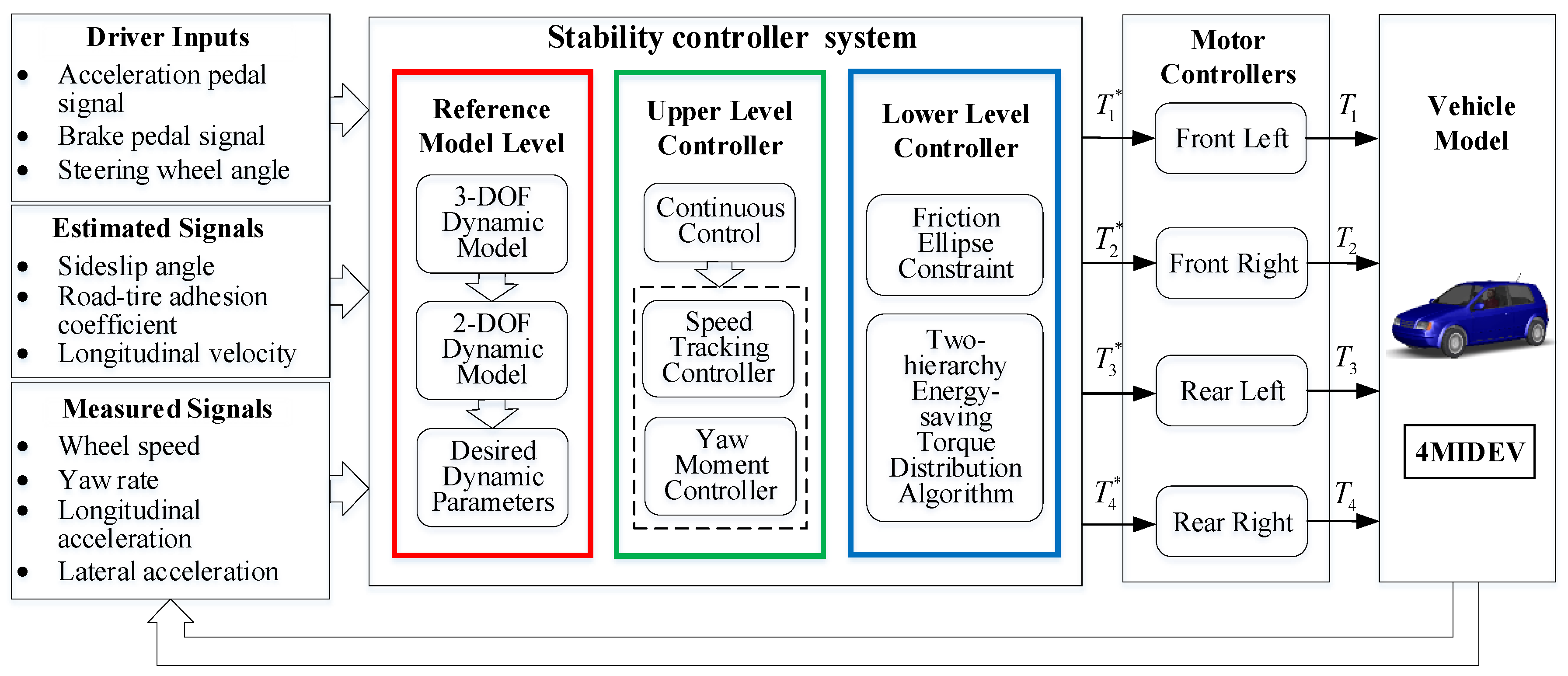
2.1. Overall Structure

The steering stability controller proposed for the 4MIDEV in this paper is designed as a hierarchical structure, including a reference model level, an upper-level controller, and a lower-level controller, as shown in Figure 1. The reference model level is designed to acquire the desired steering dynamic parameters according to the driver inputs and the estimated or measured signals. The upper-level controller generates the virtual dynamics control commands to target the desired steering dynamic parameters. The lower-level controller allocates the virtual commands to four in-wheel-motor controllers as torque commands to meet the drivers’ steering requirements. The proposed steering-stability controller schematic is shown in Figure 2. The two-degree-of-freedom (2-DOF) dynamic model is introduced in the reference model level to generate the desired yaw rate and sideslip angle for vehicle stability, according to the driver inputs and signals inputs from the driver model. The continuous upper-level controller consists of a speed-tracking controller with proportional-integral-derivative (PID) control and a yaw moment controller with fuzzy PID control, which realize the integrated control of vehicle speed, sideslip angle and yaw rate based on the 2-DOF dynamic model and drive inputs. A two-hierarchy energy-saving torque distribution algorithm is developed in the lower-level controller to distribute the motor-driving torques or the regenerative-braking torques Ti (i = 1, 2, 3, and 4). Ti* are the commands to four motor controllers from the torque distribution algorithm.

2.2. Reference Model Level

Ignoring the pitch and roll motions, there are three degrees of freedom for the vehicle’s planar motion: yaw motion, longitudinal motion, and lateral motion. A schematic of the three-degree-of-freedom (3-DOF) dynamic model is shown in Figure 3. The dynamic equations can be expressed as:
{ a x = V ˙ x V y γ = 1 m F x a y = V ˙ y + V x γ = 1 m F y γ ˙ = 1 I z M z
where a x and a y respectively denote the longitudinal and lateral acceleration, m denotes the mass of the vehicle, γ ˙ is the derivative of the yaw rate γ , V ˙ x and V ˙ y are, respectively, the derivative of the longitudinal velocity V x and the lateral velocity V y , I z is the yaw inertia of the vehicle. F x , F y , and M z are, respectively, the total longitudinal force, lateral force, and yaw moment of the vehicle, which can be defined by:
{ F x = ( F x f l + F x f r ) cos δ ( F y f l + F y f r ) sin δ + F x r l + F x r r F y = ( F y f l + F y f r ) cos δ + ( F x f l + F x f r ) sin δ + F y r l + F y r r M z = ( F y f l sin δ F x f l cos δ + F x f r cos δ F y f r sin δ ) d + ( F x r r F x r l ) d ( F y f r + F y r r ) b + ( ( F y f r + F y f l ) cos δ + ( F x f r + F x f l ) sin δ ) a
where F x i j and F y i j are, respectively, the longitudinal and lateral forces of the respective wheels, where i { f , r } denotes the front or the rear and j { l , r } denotes the left or the right.
To simplify the design and make the steady-state response of the vehicle linear with the driver input, a 2-DOF dynamic model, as shown in Figure 3, is introduced in the reference model level to generate the desired steering dynamic parameters, which reflect the driver’s intent more clearly and directly. The kinetic equations can be expressed as follows [24]:
{ m V x ( β ˙ + γ ) = F y f cos δ f + F y r I z γ ˙ = a F y f cos δ f b F y r
where γ ˙ and β ˙ are the derivatives of the yaw rate γ and the sideslip angle β , respectively, δ f is the front wheel steering angle, a and b respectively denote the distance between the center of gravity and the front axle and rear axle, F y f and F y r denote the lateral tire force of the front and rear wheels, which can be simplified to be proportional to the slip angle:
{ F y f = K f α f F y r = K r α r
where K f and K r denote the front and rear tire cornering stiffness, respectively, and α f and α r are the sideslip angles of the front wheel and rear wheel, respectively, which can be expressed as follows:
{ α f = β + a γ V x δ f α r = β b γ V x
The yaw rate and the sideslip angle are chosen as the stability representation in the 2-DOF vehicle’s stable steering characteristic. The yaw rate and the sideslip angle can be simplified as follows:
{ γ = G r δ f β = G β δ f
where G γ = 1 1 + A V x 2 V x l , G β = 1 ( m / l ) [ a / ( b K r ) ] V x 2 1 + A V x 2 b l , A = m l 2 a K f b K r K f K r , and l is the distance between the front axle and the rear axle.
The influence of the road adhesion coefficient should also be taken into account [4]:
| γ d e s | | μ g V x |
From (6) and (7), the desired yaw rate γ d e s can be expressed as follows:
| γ d e s | = min { | γ | | γ | } sign ( δ f )
where γ = μ g V .

2.3. Upper-Level Controller

The upper-level controller consists of a speed-tracking controller and a yaw-moment controller, which realize the integrated control of vehicle speed, sideslip angle, and yaw rate. In addition, the upper level is designed to work continuously during the steering maneuvers, so to ensure a better steering stability of the 4MIDEV, with the motor torques and their fluctuations reduced.

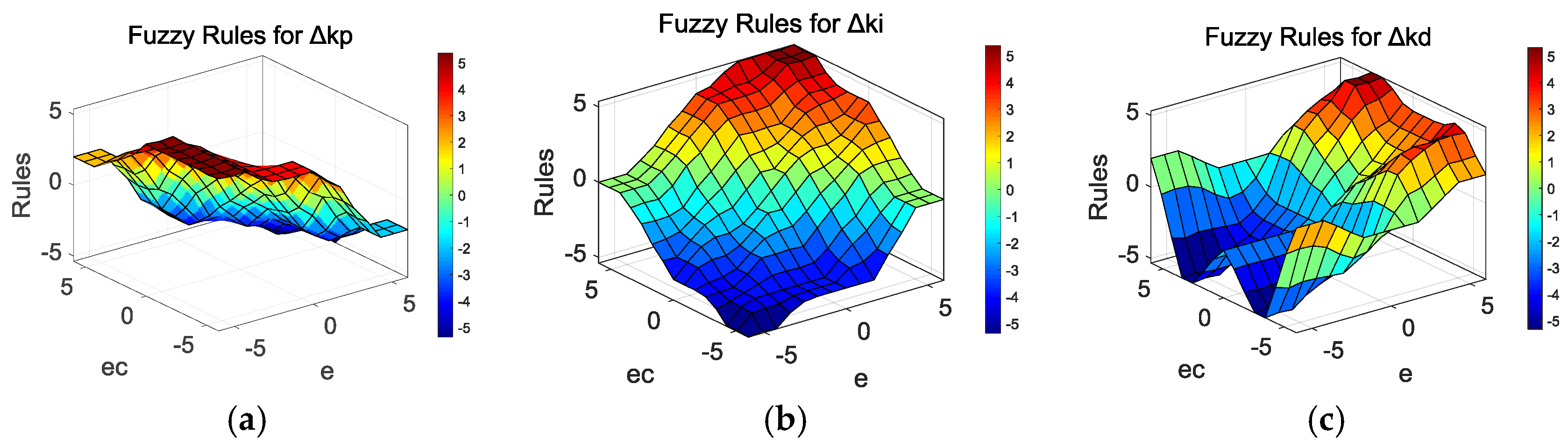
2.3.1. Speed-Tracking Controller

In order to meet the driver’s demand for speed, a speed tracking controller is built to guarantee the vehicle speed during the steering maneuvers, and the PID control method is selected to reduce the cost of calculation. The input to the speed tracking controller, as shown in Figure 2, is the longitudinal speed error Δ V x between the actual speed V x and the desired speed V x d e s , and its output is the longitudinal traction force F x d e s . The V x can be estimated by the rotation speed signal n i (i = 1, 2, 3, 4) of four in-wheel motors [25].

2.3.2. Yaw-Moment Controller

The proposed yaw-moment controller, as shown in Figure 2, is designed as a fuzzy PID controller to adapt to the nonlinear system, which chooses the sideslip angle and the yaw rate as controlled variables to calculate the target yaw moment M z d e s . The inputs of the yaw-moment controller are the errors of the vehicle yaw rate and the sideslip angle, and the output is the target yaw moment. The errors of the yaw rate and sideslip angle are treated in different ways and they are simply weighted according to their different influences on the steering stability. The fuzzy rules of the yaw rate in the yaw-moment controller are shown in Table 1, Table 2 and Table 3, in which Δ k p , Δ k i and Δ k d are, respectively, the adaptive variables of the proportion coefficient k p , integration coefficient k i , and differentiation coefficient k d . There are seven linguistic terms to describe the values of inputs and outputs, i.e., Negative-Big (NB), Negative-Medium (NM), Negative-Small (NS), Zero (Z), Positive-Small (PS), Positive-Medium (PM), and Positive-Big (PB). The relevant fuzzy surfaces of Δ k p , Δ k i , and Δ k d are shown in Figure 4. The fuzzy rules are determined by a large amount of data and experience. Some basic relationships can be used for qualitative reasoning: (1) in the case of big errors, in order to speed up the system response and avoid large overshoot, big Kp and small Kd and Ki can be taken; (2) when the errors are medium, small Kp and appropriate Kd and Ki can be used to make the system overshoot smaller; (3) when the errors are small, big Kp and Ki and appropriate Kd can be taken to make the system have a better steady-state performance.

2.4. Lower-Level Controller

The lower level controller allocates the target yaw moment and the equivalent traction force from the upper-level controller to four in-wheel-motor controllers as driving/regenerative braking torque commands, so as to achieve the desired steering operation.
The tire longitudinal force F x and target yaw moment M z can be simplified as follows [4]:
{ F x = F x f l cos δ f + F x f r cos δ f + F x r l + F x r r M z = d ( F x f l c o s δ f + F x f r c o s δ f F x r l + F x r r ) + a F x f l sin δ f + a F x f r sin δ f
The relationship between the lower-level controller and the upper-level controller is thus expressed as follows:
v = B u
where u = [ T f l T f r T r l T r r ] T , v = [ F x d e s    M z d e s ] T , B = 1 R [ cos δ f cos δ f 1 1 d cos δ f + a sin δ f d cos δ f + a sin δ f d d ] .

2.4.1. Friction Ellipse Constraint

During the torque distribution in the lower-level controller, the road adhesion constraint, i.e., the friction ellipse constraint, should be taken into account in order to avoid the longitudinal and lateral tire forces from exceeding the road adhesion limit. The friction ellipse constraint can be expressed as:
F x i j 2 + F y i j 2 ( μ i j F z i j ) 2
where F z i j denotes the vertical load on the corresponding wheel and μ i j is the tire–road adhesion coefficient. The longitudinal tire force F x i j is related to the torque applied on the wheel, which can be expressed as:
ω ˙ i j = 1 J c ( T i j F x i j R M f i j )
where ω ˙ i j denotes the wheel angle acceleration, J c denotes the moment of inertia, T i j is the driving/braking torque applied on the wheel, R is the rolling radius, M f i j is the rolling resistance moment. In general, the dynamics response of the wheels is much faster than the vehicle dynamics response, and the traction/braking torque T i j can be expressed as:
T i j = F x i j R + M f i j
The lateral tire force F y i j in (11) can be calculated from the tire model. In order to improve the real-time performance of the system, the simplified tire model in [7] is used as follows:
F y i j = K α i j 1 ( F x i j μ i j F z i j ) 2 μ i j k tan 1 ( k μ i j α i j ) k = K α i j π 2 F z i j
where μ i j is the road adhesion coefficient, k is a constant coefficient, K α i j is the lateral stiffness of each tire, and α i j denotes the tire slip angle; α i j and F z i j can be obtained as follows [22]:
{ α f l = δ f + tan 1 ( V y + γ a V x γ d ) α f r = δ f + tan 1 ( V y + γ a V x + γ d ) α r l = tan 1 ( V y γ b V x γ d ) α r r = tan 1 ( V y γ b V x + γ d )
{ F z f l = m g b 2 l m a x h 2 l m a y h b 2 d l F z f r = m g b 2 l m a x h 2 l + m a y h b 2 d l F z r l = m g a 2 l + m a x h 2 l m a y h a 2 d l F z r r = m g a 2 l + m a x h 2 l + m a y h a 2 d l
where m ω denotes the total mass of the wheel, h is the height of the center of gravity to the ground, and d is half of the tread.

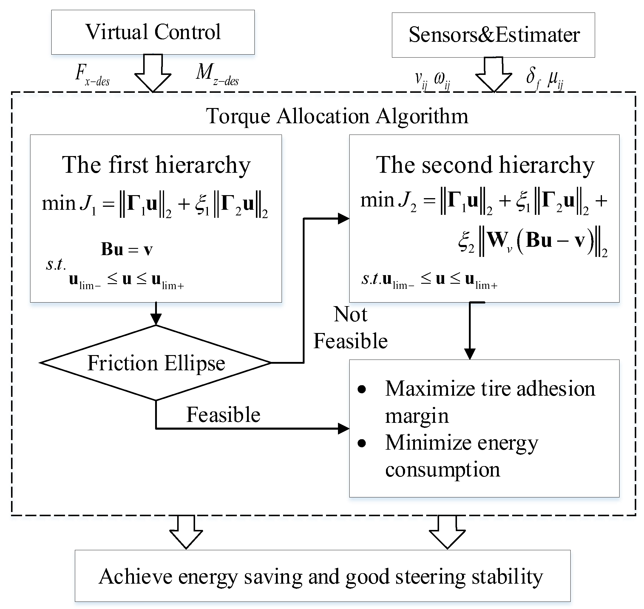
2.4.2. Energy-Saving Torque Distribution Algorithm

An adaptive two-hierarchy energy-saving torque distribution algorithm is developed in the lower-level controller to realize the multi-objective optimization of energy saving and steering stability based on torque distribution, as shown in Figure 5.
In this paper, tire workload usages and total instantaneous power are selected to reflect the vehicle steering stability and energy consumption efficiency, respectively, which can be formulated as:
Ω 1 = F x i j 2 μ i j 2 F z i j 2
Ω 2 = F x i j 2 R 2 ω i j 2
With the decrease of the tire objective Ω 1 and the power objective Ω 2 , the vehicle stability margin and the energy consumption will be respectively increased and reduced.
In addition, considering that the friction ellipse constraint is non-linear, the difficulty and time of solving will increase if it is introduced directly into the optimization process. However, if the friction ellipse constraint is linearized, the accuracy of the solution will also be affected. Therefore, the friction ellipse constraint, in this paper, is introduced as a basis for judging whether the two-hierarchy distribution algorithm needs to be switched.
(1) The main target of the first-hierarchy torque distribution algorithm is to maximize stability margin and energy consumption efficiency, while the torque distribution fully satisfies the virtual commands from the upper-level controller. This optimization problem can be formulated as:
min J 1 = F x i j 2 μ i j 2 F z i j 2 + ξ 1 ( F x i j R ω i j ) 2
Constraint: { B u = v u lim < u < u lim + .
where ξ1 is the weighting factor of the energy consumption penalty term. The above equations can be written in matrix form:
min J 1 = Γ 1 u 2 + ξ 1 Γ 2 u 2
Γ 1 = d i a g ( 1 R μ i j F z i j ) Γ 2 = d i a g ( ω i j )
The results of the above optimization problem are then substituted into (13) and (14) to obtain the longitudinal and lateral tire forces, so as to further determine if the friction ellipse constraint is satisfied. If there is no feasible solution to the optimization problem or the feasible solution exceeds the friction ellipse constraint, the algorithm will be switched to the second hierarchy.
(2) In the second-hierarchy torque distribution algorithm, the equality constraint B u = v is converted to min W v ( B u v ) 2 and introduced into (20) as a penalty item to reduce the constraint intensity of the control error. The optimization problem can be reformulated as:
min J 2 = Γ 1 u 2 + ξ 1 Γ 2 u 2 + ξ 2 W v ( B u v ) 2
Constraint: u lim < u < u lim + .
where Wv represents the distribution weight matrix and ξ2 is the weighing coefficient.
The (22) can be simplified as follows:
J 2 = arg min u lim u u lim + ( ξ 2 1 2 W v B Γ 1 Γ 1 ) u ( ξ 2 1 2 W v v 0 0 ) 2 2 = A u C 2 2
The above equation can be solved by the active set method to obtain the value of each in-wheel-motor torque.

3. Simulation Analysis

The proposed stability controller for the 4MIDEV was implemented and evaluated in the co-simulation based on Matlab/Simulink (R2016a, MathWorks, Natick, MA, USA) and CarSim (2016.1, Mechanical Simulation Corporation, Ann Arbor, MI, USA). To further prove the improvement in energy savings and steering stability, the proposed stability controller, referred to as “energy-saving continuous control,” was compared with other two controllers. One of the two controllers, referred to as “servo control” in this paper, is proposed in [4] and only works after the vehicle is judged to be losing stability, whereas the other controller is referred to as “ordinary continuous control” and works continuously, adopting the torque distribution algorithm proposed in [4]. The aforementioned stability controllers were evaluated at step steer maneuver and double-lane-change (DLC) maneuver under different conditions. The parameters of the vehicle and in-wheel motors used in this study are presented in Table 4.

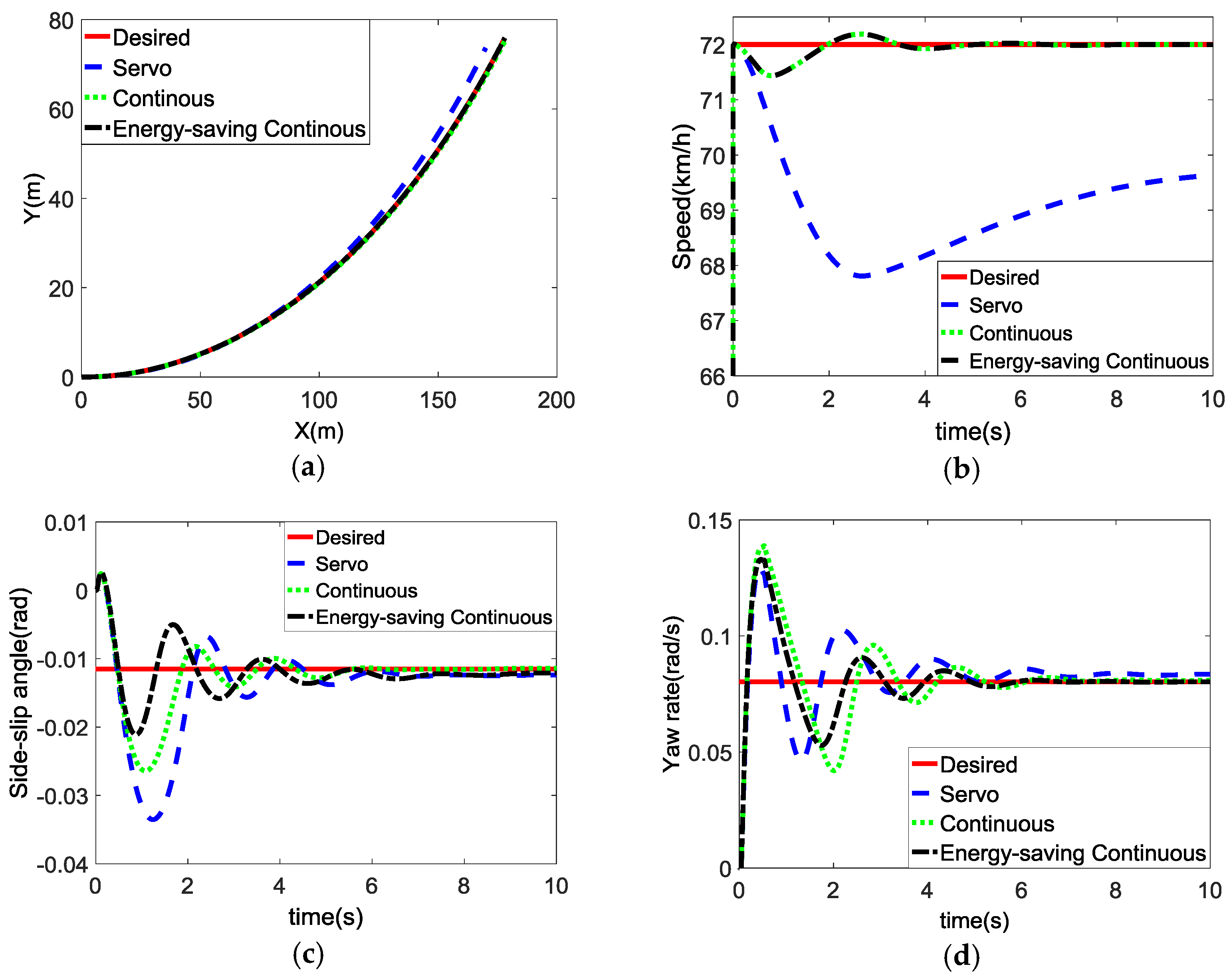
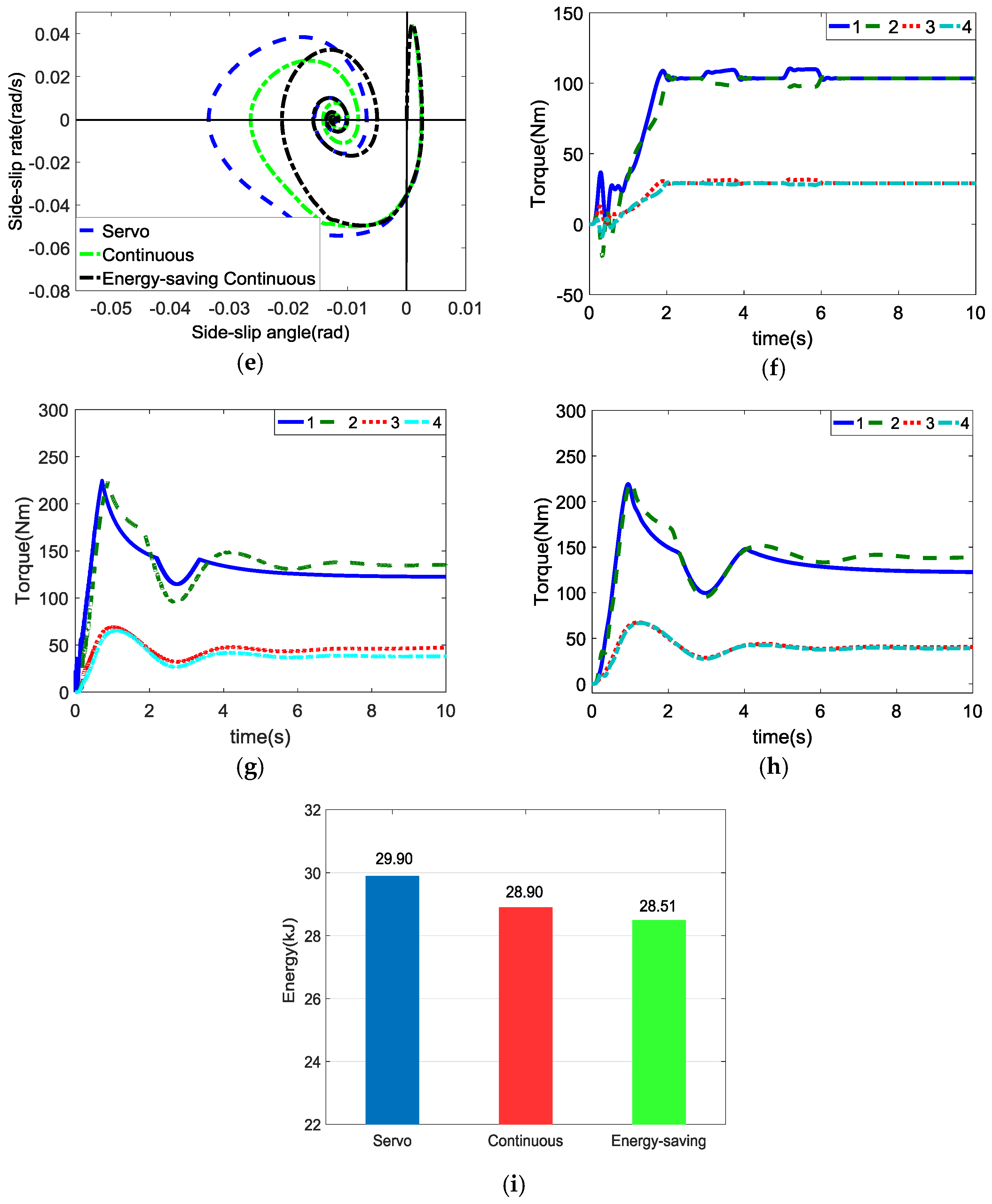
3.1. Step Steer Maneuve
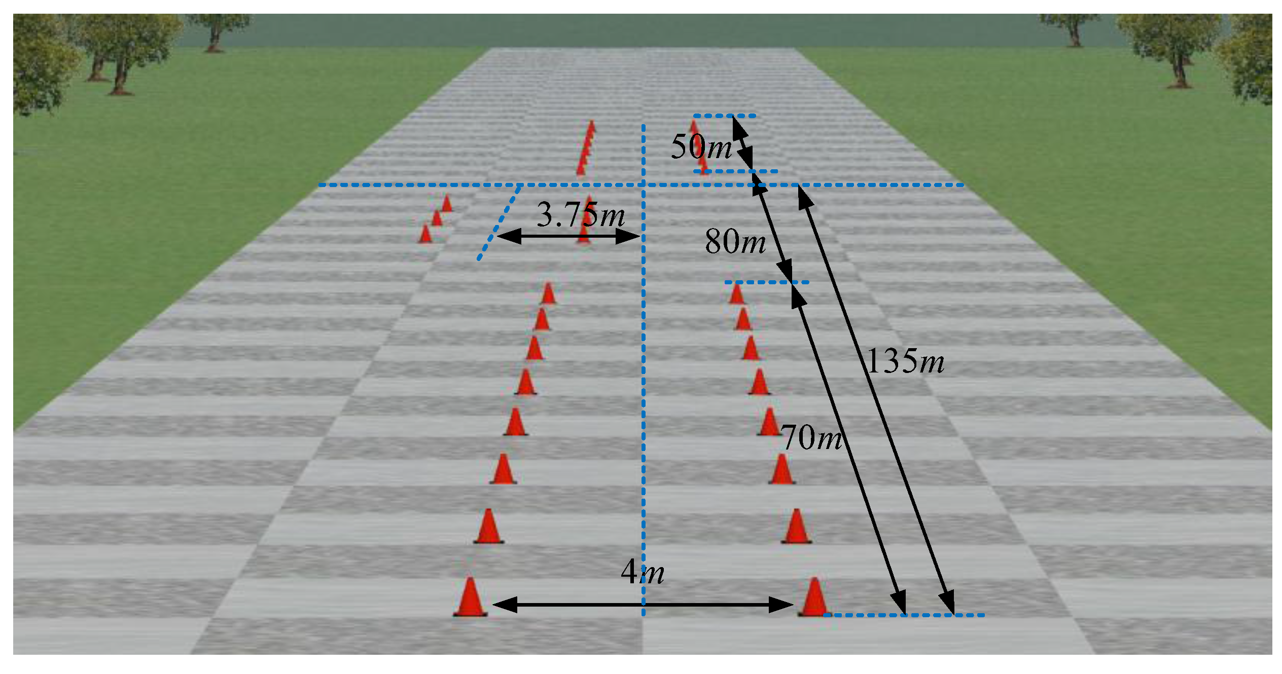
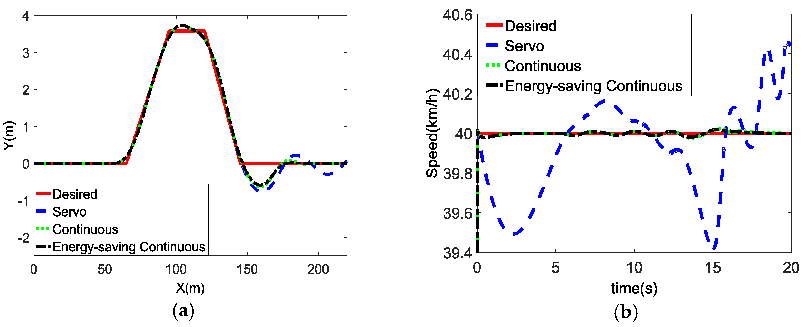
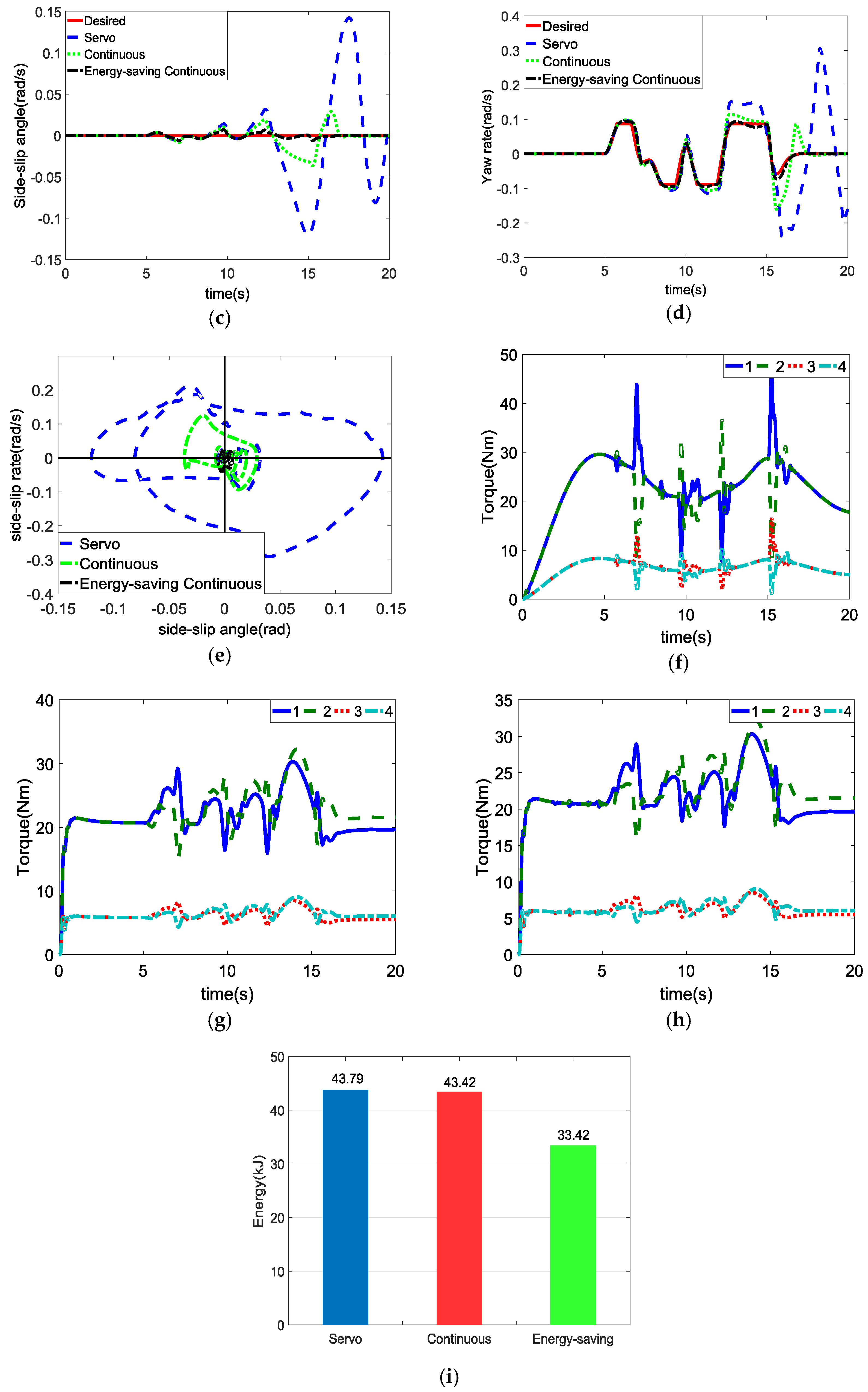
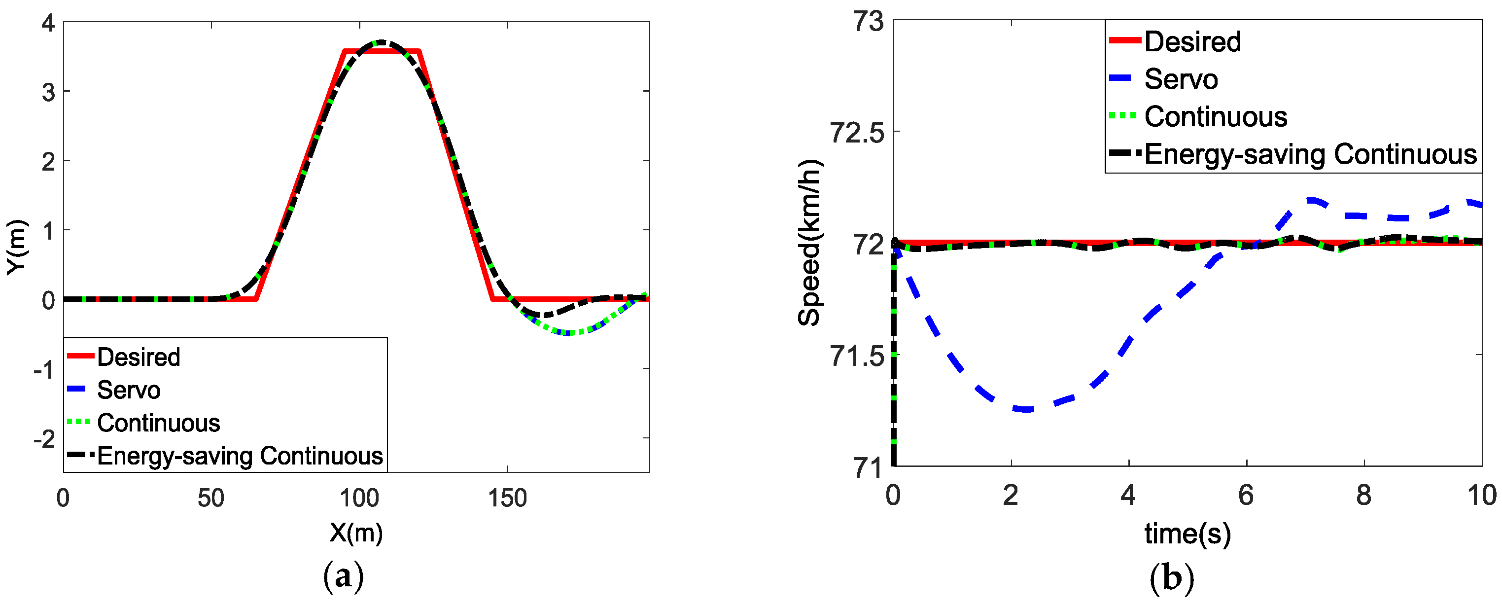
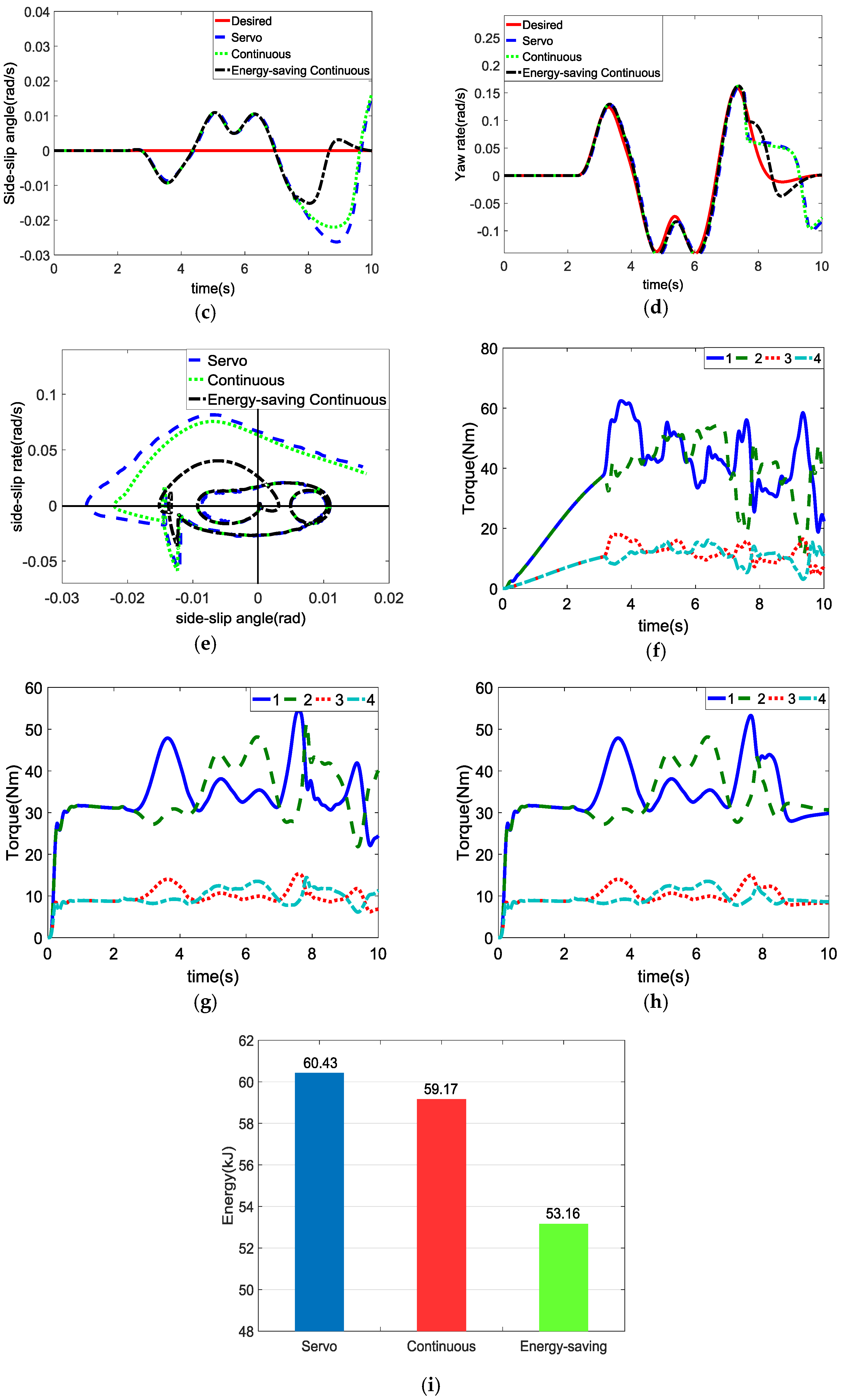
The open-loop simulation for a step steer maneuver was conducted at a constant speed of 72 km/h on asphalt road with μ = 0.75 , with the steering wheel angle increasing from 0° to 72° in 0.5 s and held until the maneuver was completed. The steering angle increased from 0° to about 7°. The vehicle dynamics responses are shown in Figure 6.
Figure 6a,b show the vehicle’s track and speed response, respectively, under the three aforementioned stability controllers. It can be seen that the trajectory and speed of the servo controls deviated from the desired value, with the speed reduced to 68 km/h. Nevertheless, the vehicles under the continuous control and energy-saving continuous control could basically follow the desired trajectory while maintaining the constant speed.
Figure 6c,d show the sideslip angle and yaw rate response of the vehicle, respectively. Under the energy-saving continuous control, the sideslip angle and yaw rate had the shortest response time and the minimum overshoot. In addition, the ordinary continuous control showed a worse steering dynamics response, and the servo control was the worst.
Figure 6e shows the sideslip angle and sideslip angle rate in the phase plane, where the controller with the plots most centralized to the origin is supposed to perform the best stability control [10,26]. The curves related to the servo control, ordinary continuous control, and energy-saving continuous control, tended to be more focused on the origin, which means that the stability control effect of the aforementioned controllers increased gradually.
Figure 6f–h show the torque of each in-wheel motor under the servo control, ordinary continuous control, and energy-saving continuous control, respectively. It can be seen that the servo stability controller has a more stable motor torque output than the other two controllers because it does not work unless the vehicle is about to lose stability. Despite the good torque response under the servo control, the servo control sacrifices vehicle stability and controllability considering the response of the other stability parameters.
Figure 6i shows the total energy consumed by the in-wheel motors under the control of three aforementioned controllers in the step steer maneuver, respectively. The energy-saving continuous control, compared with the other controls, had the highest energy consumption efficiency. It is noteworthy that, compared with the servo control, the energy-saving continuous control can reduce energy consumption by 4.6% even in 10 s.

3.2. DLC Maneuver

The closed-loop simulations for the DLC maneuver were respectively conducted on slippery road and joint road, as shown in Figure 7. The driver preview time was set to 0.5 s to study the driver–vehicle system for emergency avoidance.

3.2.1. Slippery Road: μ = 0.1

The adhesion coefficient of the slippery road was set to 0.1, and the speed of the vehicle remained constant at 40 km/h during the DLC maneuver. The simulation results are shown in Figure 8.
Figure 8a,b show the vehicle’s track and speed response, respectively. It can be seen that, after the vehicle enters the second straight line, the trajectory of the servo control produces a quasi-continuous oscillation with a large fluctuation of the vehicle speed, indicating that the vehicle almost loses its stability. However, the energy-saving continuous control and ordinary continuous control can restrain the trend of instability before the vehicle loses controllability, and the energy-saving continuous control performs a little better.
Figure 8c,d show the sideslip angle and the yaw rate response of the vehicle, respectively. Both the sideslip angle and the yaw rate of the servo control and ordinary continuous control appeared to deviate from the desired values when the vehicle was entering the second straight section, i.e., after about 13 s. However, the energy-saving continuous control could make these two quantities basically follow the desired values, which indicates that the steering stability can be ensured even under extreme conditions.
Figure 8e shows the sideslip angle and sideslip angle rate in the phase plane. The curve of the energy-saving continuous control is mostly concentrated on the origin, which means that the energy-saving continuous control, compared with the other controls, has the best performance in stability control. In addition, the stability responses under continuous control are better than those under servo control
Figure 8f–h show the torque of each in-wheel motor under the servo control, ordinary continuous control, and energy-saving continuous control, respectively. It can be seen that the continuous control can achieve a smaller and more stable torque output than the servo control, which reflects the advantages of a distributed drive.
Figure 8i shows the total energy consumed by the in-wheel motors under the control of the three aforementioned controllers in the DLC maneuver on slippery road. The energy-saving continuous control, compared with the servo control and the ordinary continuous control, reduced the energy consumption by about 23.68% to 23.03% in 20 s respectively, which is an obvious improvement in energy saving.

3.2.2. Joint Road: μ = 0.75–0.1

The adhesion coefficient of the joint road was initially set to 0.75 and suddenly changed to 0.1 when the vehicle was about to complete the final steering operation at a distance of 135 m from the starting position, as shown in the Figure 7. The speed of the vehicle remained constant at 72 km/h during the DLC maneuver. The simulation results are shown in Figure 9.
Figure 9a,b show the vehicle’s track and speed response, respectively. It can be seen that all the tracks of the three aforementioned controllers appeared to deviate from the scheduled track when the road adhesion coefficient was abruptly changed after about 8 s. Nevertheless, energy-saving strategies can suppress disturbances in the shortest time and better maintain the steering stability while maintaining the desired speed.
Figure 9c,d show the sideslip angle and yaw rate response of the vehicle, respectively. Figure 9e shows the sideslip angle and sideslip angle rate in the phase plane. Both the sideslip angle and the yaw rate of the three aforementioned controllers began at different degrees of disturbance after about 8 s. However, the energy-saving continuous control, compared with the other controls, restrained the disturbance in a relatively fast time, thus achieving the best steering stability.
Figure 9f–h show the torque of each in-wheel motor under the servo control, ordinary continuous control, and energy-saving continuous control, respectively. It can be seen that the proposed energy-saving controller could achieve the most stable torque output, while the torque under the other controllers began to fluctuate as the adhesion coefficient changed.
Figure 9i shows the total energy consumed by the in-wheel motors under the control of three aforementioned controllers in the DLC maneuver on joint road. Compared with the servo controller and the ordinary continuous controller, the proposed energy-saving controller could reduce the energy consumption by 12.03% and 10.16% in 10 s, respectively.

4. Conclusions

This paper proposes a continuous steering stability controller based on an energy-saving torque distribution algorithm for a four in-wheel-motor-independent-drive electric vehicle to improve the energy consumption efficiency while maintaining the steering stability. The proposed controller consists of a reference model level, an upper-level controller, and a lower-level controller. The reference model level is used to generate the desired vehicle dynamics parameters such as sideslip angle and yaw rate. The upper-level controller works continuously during the steering maneuvers to achieve the integrated control of the yaw rate and the sideslip angle, rather than performing first a stability judgement. An adaptive two-hierarchy energy-saving torque distribution algorithm is developed in the lower-level controller to realize the multi-objective optimization of energy saving and steering stability on the basis of torque distribution.
The proposed stability controller for the 4MIDEV was implemented and evaluated in the co-simulation based on Matlab/Simulink and CarSim, where the step steer maneuver and the double-lane-change maneuver were conducted under different conditions. The results show that the proposed controller, compared with the conventional servo controller and ordinary continuous controller, can reduce energy consumption up to 23.68% and improve the vehicle steering stability. In future work, the controller will be tested through the hardware-in-the-loop test, and then the platform test.

Acknowledgments

This work was supported by the National Natural Science Foundation of China for financially supporting this project (51475045).

Author Contributions

Li Zhai and Tianmin Sun proposed the innovation of the overall system and helped with the control methods, Rufei Hou developed the control strategy and the simulation. Li Zhai and Rufei Hou wrote the manuscript and Steven Kavuma polished the manuscript. All authors read and approved the manuscript.

Conflicts of Interest

The authors declare no conflict of interest.

References

  1. Liu, M.; Gu, F.; Zhang, Y. Ride Comfort Optimization of In-Wheel-Motor Electric Vehicles with In-Wheel Vibration Absorbers. Energies 2017, 10, 1647. [Google Scholar] [CrossRef]
  2. Zhang, X.; Göhlich, D. Integrated Traction Control Strategy for Distributed Drive Electric Vehicles with Improvement of Economy and Longitudinal Driving Stability. Energies 2017, 10, 126. [Google Scholar] [CrossRef]
  3. Zhai, L.; Huang, H.; Kavuma, S. Investigation on a Power Coupling Steering System for Dual-Motor Drive Tracked Vehicles Based on Speed Control. Energies 2017, 10, 1118. [Google Scholar] [CrossRef]
  4. Zhai, L.; Sun, T.; Wang, J. Electronic Stability Control Based on Motor Driving and Braking Torque Distribution for a Four In-Wheel Motor Drive Electric Vehicle. IEEE Trans. Veh. Technol. 2016, 65, 4726–4739. [Google Scholar] [CrossRef]
  5. Ono, E.; Hattori, Y.; Muragishi, Y.; Koibuchi, K. Vehicle dynamics integrated control for four-wheel-distributed steering and four-wheel-distributed traction/braking systems. Veh. Syst. Dyn. 2006, 44, 139–151. [Google Scholar] [CrossRef]
  6. Xu, D.; Wang, G.; Cao, B.; Feng, X. Study on optimizing torque distribution strategy for independent 4WD electric vehicle. J. Xian Jiaotong Univ. 2012, 68, 42–46. [Google Scholar]
  7. Chen, Y.; Wang, J. Design and Evaluation on Electric Differentials for Overactuated Electric Ground Vehicles with Four Independent In-Wheel Motors. IEEE Trans. Veh. Technol. 2012, 61, 1534–1542. [Google Scholar] [CrossRef]
  8. Wang, J.; Longoria, R.G. Coordinated and Reconfigurable Vehicle Dynamics Control. IEEE Trans. Control Syst. Technol. 2009, 17, 723–732. [Google Scholar] [CrossRef]
  9. Zhao, H.; Ren, B.; Chen, H.; Deng, W. Model predictive control allocation for stability improvement of four-wheel drive electric vehicles in critical driving condition. IET Control Theory Appl. 2015, 9, 2688–2696. [Google Scholar] [CrossRef]
  10. Song, P.; Tomizuka, M.; Zong, C. A novel integrated chassis controller for full drive-by-wire vehicles. Veh. Syst. Dyn. 2015, 53, 215–236. [Google Scholar] [CrossRef]
  11. Li, B.; Goodarzi, A.; Khajepour, A.; Chen, S.K.; Litkouhi, B. An optimal torque distribution control strategy for four-independent wheel drive electric vehicles. Veh. Syst. Dyn. 2015, 53, 1172–1189. [Google Scholar] [CrossRef]
  12. He, P.; Hori, Y. Optimum traction force distribution for stability improvement of 4WD EV in critical driving condition. In Proceedings of the IEEE International Workshop on Advanced Motion Control, Istanbul, Turkey, 27–29 March 2006; pp. 596–601. [Google Scholar]
  13. Novellis, L.D.; Sorniotti, A.; Gruber, P.; Orus, J.; Fortun, J.M.R.; Theunissen, J.; Smet, J.D. Direct yaw moment control actuated through electric drivetrains and friction brakes: Theoretical design and experimental assessment. Mechatronics 2015, 26, 1–15. [Google Scholar] [CrossRef] [Green Version]
  14. Nam, K.; Fujimoto, H.; Hori, Y. Lateral Stability Control of In-Wheel-Motor-Driven Electric Vehicles Based on Sideslip Angle Estimation Using Lateral Tire Force Sensors. IEEE Trans. Veh. Technol. 2012, 61, 1972–1985. [Google Scholar]
  15. Zhang, H.; Wang, J. Vehicle Lateral Dynamics Control through AFS/DYC and Robust Gain-Scheduling Approach. IEEE Trans. Veh. Technol. 2016, 65, 489–494. [Google Scholar] [CrossRef]
  16. Zhang, L. Vehicle Stability Enhancement through Hierarchical Control for a Four-Wheel-Independently-Actuated Electric Vehicle. Energies 2017, 10, 947. [Google Scholar]
  17. Hu, J.S.; Wang, Y.; Fujimoto, H.; Hori, Y. Robust Yaw Stability Control for In-wheel Motor Electric Vehicles. IEEE/ASME Trans. Mechatron. 2017, 22, 1360–1370. [Google Scholar] [CrossRef]
  18. Ding, S.; Liu, L.; Zheng, W. Sliding Mode Direct Yaw-Moment Control Design for In-Wheel Electric Vehicles. IEEE Trans. Ind. Electron. 2017, 64, 6752–6762. [Google Scholar] [CrossRef]
  19. Kang, J.; Yoo, J.; Yi, K. Driving Control Algorithm for Maneuverability, Lateral Stability, and Rollover Prevention of 4WD Electric Vehicles with Independently Driven Front and Rear Wheels. IEEE Trans. Veh. Technol. 2011, 60, 2987–3001. [Google Scholar] [CrossRef]
  20. Li, B.; Du, H.; Li, W. Optimal Distribution Control of Non-Linear Tire Force of Electric Vehicles with In-Wheel Motors. Asian J. Control 2016, 18, 69–88. [Google Scholar] [CrossRef]
  21. Kim, W.; Son, Y.S.; Chung, C.C. Torque-Overlay-Based Robust Steering Wheel Angle Control of Electrical Power Steering for a Lane-Keeping System of Automated Vehicles. IEEE Trans. Veh. Technol. 2016, 65, 4379–4392. [Google Scholar] [CrossRef]
  22. Yamakawa, J.; Kojima, A.; Watanabe, K. A method of torque control for independent wheel drive vehicles on rough terrain. J. Terramech. 2007, 44, 371–381. [Google Scholar] [CrossRef]
  23. Jin, L.Q.; Liu, Y. Study on Adaptive Slid Mode Controller for Improving Handling Stability of Motorized Electric Vehicles. Math. Probl. Eng. 2014, 2014, 240857. [Google Scholar] [CrossRef]
  24. Kim, D.; Kim, H. Vehicle Stability Control with Regenerative Braking and Electronic Brake Force Distribution for a Four-Wheel Drive Hybrid Electric Vehicle. Proc. Inst. Mech. Eng. Part D J. Automob. Eng. 2006, 220, 683–693. [Google Scholar] [CrossRef]
  25. Wang, Z.; Liu, M.; Zhou, Y. Estimation of Longitudinal Speed of In-wheel Motor Driven Vehicle Using Fuzzy Extended Kalman Filter. J. Southwest Jiaotong Univ. 2015, 6, 1094–1099. [Google Scholar] [CrossRef]
  26. Zhang, H.; Li, X.; Shi, S.; Liu, H.; Guan, R.; Liu, L. Phase Plane Analysis for Vehicle Handling and Stability. Int. J. Comput. Intell. Syst. 2011, 4, 1179–1186. [Google Scholar] [CrossRef]
Figure 1. Configuration of the proposed steering-stability controller.
Energies 11 00350 g001
Figure 2. Schematic of the proposed steering-stability controller.
Energies 11 00350 g002
Figure 3. Dynamic models of the 4MIDEV.
Energies 11 00350 g003
Figure 4. The fuzzy rules for the yaw-moment controller: (a) fuzzy rules for Δkp; (b) fuzzy rules for Δki; (c) fuzzy rules for Δkd.
Energies 11 00350 g004
Figure 5. The structure of the energy-saving torque distribution algorithm.
Energies 11 00350 g005
Figure 6. Simulation results for the step steer maneuver on asphalt road (μ = 0.75): (a) track; (b) Speed; (c) sideslip angle; (d) yaw rate; (e) phase plane; (f) torque under the servo control; (g) torque under the ordinary continuous control; (h) torque under the energy-saving continuous control; (i) total energy consumption.
Energies 11 00350 g006aEnergies 11 00350 g006b
Figure 7. The path of the DLC maneuver.
Energies 11 00350 g007
Figure 8. Simulation results for DLC on slippery road (μ = 0.1): (a) track; (b) speed; (c) sideslip angle; (d) yaw rate; (e) phase plane; (f) torque under the servo control; (g) torque under the ordinary continuous control; (h) torque under the energy-saving continuous control; (i) total energy consumption.
Energies 11 00350 g008aEnergies 11 00350 g008b
Figure 9. Simulation results for DLC on joint road (μ = 0.75–0.1): (a) track; (b) speed; (c) sideslip angle; (d) yaw rate; (e) phase plane; (f) torque under the servo control; (g) torque under the ordinary continuous control; (h) torque under the energy-saving continuous control; (i) total energy consumption.
Energies 11 00350 g009aEnergies 11 00350 g009b
Table 1. The fuzzy rules of Δkp.
Δkpe(s)
NBNMNSZPSPMPB
Δe(s)NBPBPBPMPMPSNSNS
NMPBPBPMPMPSNSNS
NSPBPBPMPSNSNMNM
ZPBPBPMZNSNMNB
PSPMPMPSNSNMNBNB
PMPSPSNSNMNMNBNB
PBPSPSNSNMNMNBNB
Table 2. The fuzzy rules of Δki.
Δkie(s)
NBNMNSZPSPMPB
Δe(s)NBNBNBNMNMNMZZ
NMNBNMNMNMNSZZ
NSNMNMNSNSZPSPS
ZNMNSNSZPSPSPM
PSNSNSZPSPSPMPM
PMZZPSPMPMPBPB
PBNBNBNMNMNMZZ
Table 3. The fuzzy rules of Δkd.
Δkde(s)
NBNMNSZPSPMPB
Δe(s)NBPSPSZZZPSPB
NMNBNBNMNSPMPBPM
NSNBNBNMNSPSPSPM
ZNSNSNSNSZPSPB
PSNBNBNMNSPSPBPB
PMNBNBNMNSPMPBPB
PBPSPSZZZPSPS
Table 4. The parameters of the vehicle and in-wheel motors.
NameSymbolValue
vehicle massm1411 kg
length from the center of gravity (CG) to the front wheel axisa1.04 m
length from the CG to the rear wheel axisb1.56 m
tread widthd1.48 m
tire radiusr0.3 m
height of the center of masshg0.54 m
moment of inertia about the yaw axisIz2031.4 kgm3
rated powerPe14 kW
maximum powerPm28 kW
rated speedne800 rpm
maximum speednm1200 rpm
rated torqueTe170 Nm
maximum torqueTm340 Nm

