1. Introduction
Electrification in commercial and military ships has been a trend in recent past in order to reduce emissions and to improve efficiency [
1,
2,
3,
4]. The International Marine Organization (IMO) in 2012 stated that global SO
x and NO
x emissions from entire shipping exhibits about 13% and 15% of global SO
x and NO
x respectively [
5]. It further states that for international shipping total CO
2 emissions are around 796 million tons, which are approximately 2.2% of the global CO
2 emissions. The CO
2 emissions from ships all over the globe is found to be 2.6% of the global CO
2 emissions. Moreover, IMO predicts that by 2050, CO
2 emissions in case of international shipping could raise in between 50% to 250%. IMO announced guidelines and regulations in Jan 2015 for Emission Controlled Areas (ECA) as a consequence of modifications applied in the International Convention of the Prevention of Pollution from ships [
6]. The European Commission set forth a novel climate agreement (
the Paris Protocol) with an elongated ambition of diminishing global emissions up to 60% by 2050 as compared to 2010 levels [
7].
In past, cost of energy and environmental concerns were not of greater importance as of now in marine power systems. In order to save fuel and decrease emissions, several solutions have been proposed. For instance: substituting alternative fuels, exhaust gases after treatment, and using hybrid propulsions are the frequently applied approaches implemented to achieve environmental guidelines imposed by IMO. However, these solutions for reducing emissions (SOx, NOx, CO2, etc.) are not fundamental. Therefore, novel concepts such as hybrid energy storage systems (HESS) should be investigated in the shipboard microgrids.
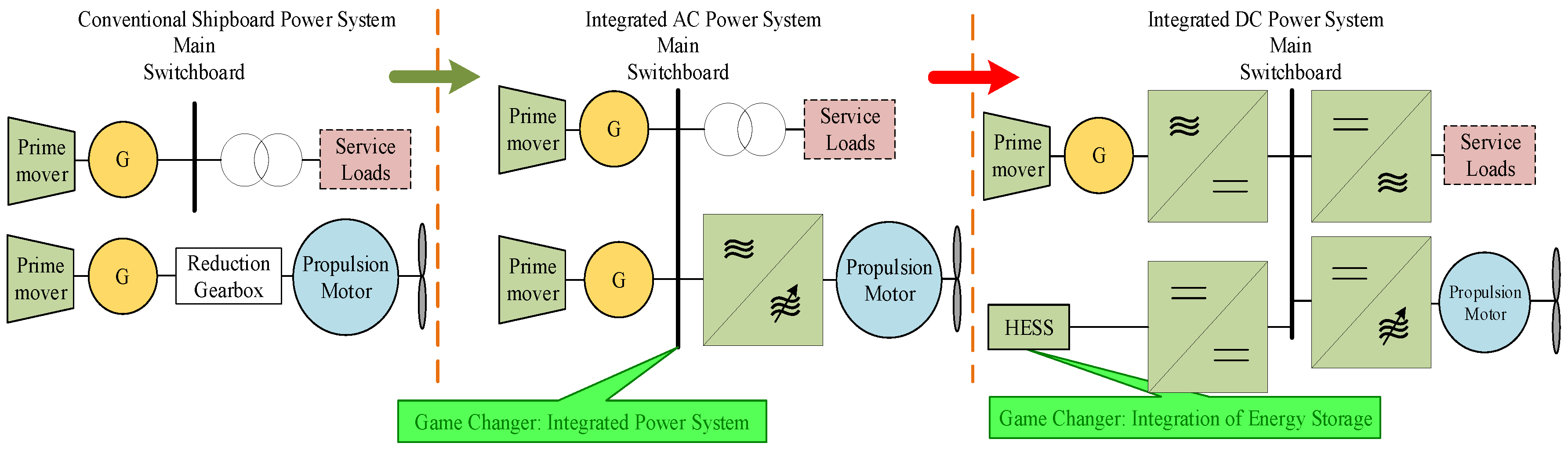
There is an enormous evolvement over past few decades in shipboard microgrids due to their complex power architecture, power electronics interface based high power sources and loads. Hence, modern shipboard microgrids have become almost similar to terrestrial islanded microgrids, but due to the presence of high dynamic loads, complex control, and power management further complex the shipboard microgrids compared to terrestrial microgrids. Traditional power system relies on radial structure, which is used to have a separate generation for service and propulsion loads. However, due to the development of power electronics-based devices, the use of common power systems for both propulsion and service loads have been growing in the past few decades.
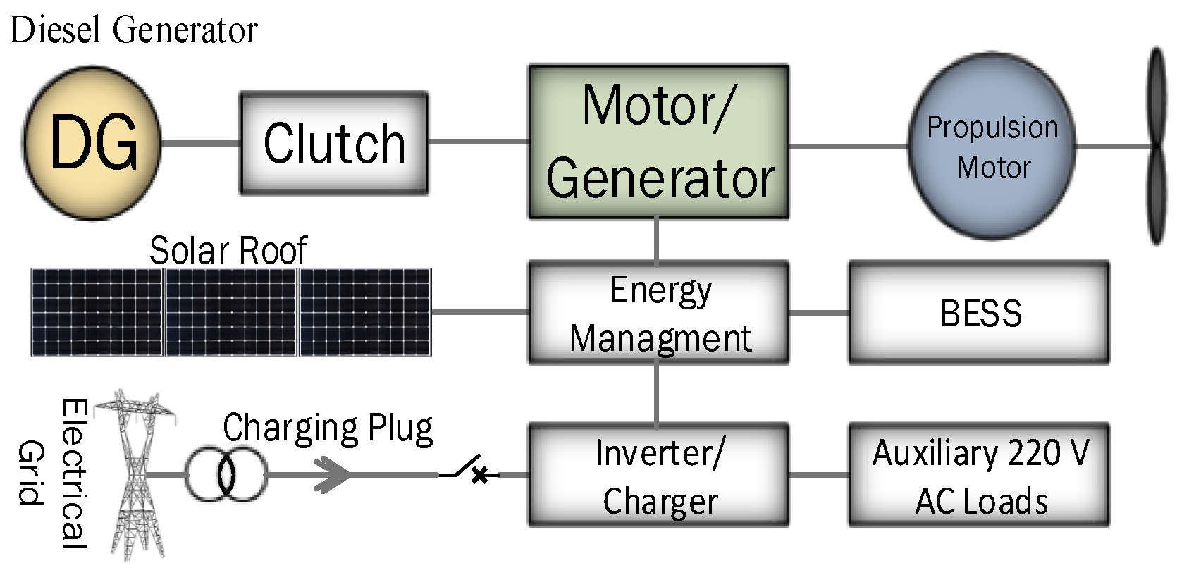
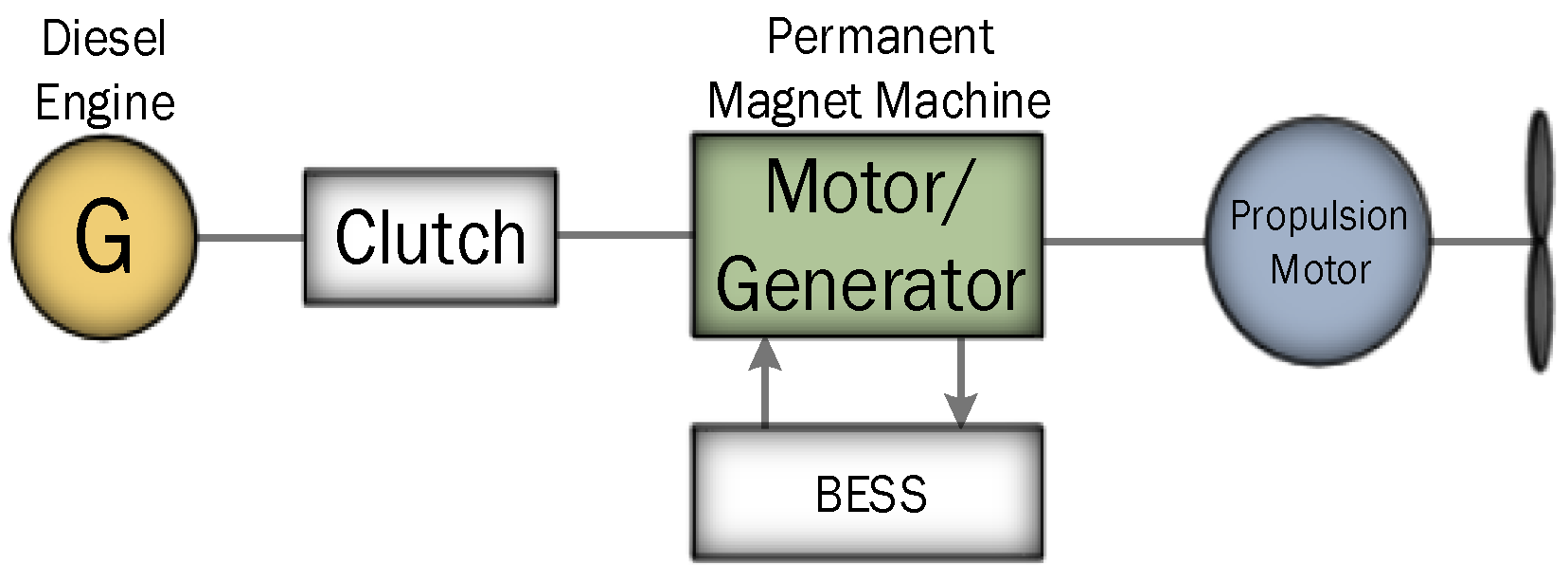
Figure 1 depicts a single line diagram of the evolution of shipboard power systems.
The fast growth of electric and hybrid transportation systems open doors for further developments in ESS. Currently, the solutions are not technologically and commercially adequate in several features causing barriers to their broader usage. The ESS technologies vary from each other in terms of expense and technical aspects such as power density, energy density, charge and discharge time, operating temperature, lifetime, environmental impact, and maintenance requirement. Several works have been conducted in recent years, especially in the last decade, to improve ESS capacity. A typical single ESS technology, which can provide higher power and energy density, greater lifetime, and other such specifications, is not likely to be developed in near future. Therefore, in order to improve the capabilities, two or more ESS technologies can be hybridized.
Numerous modern technologies are being introduced in the maritime industry to meet the regulations imposed by various authorities. These technologies include liquid natural gas (LNG) as an alternative fuel, exhaust catalyst, hybrid propulsion, and so on. The implementation of Integrated Power Systems (IPS) have been firstly implemented in terrestrial Microgrid, then this application is extended to All Electric Ships (AES). The increased concerns over fuel economy and environmental issues have enforced maritime transport industry to hunt for fuel-efficient and lesser emission solutions. In marine vessels, power electronics offer a major role in fuel saving, particularly by the integration of ESS and electrification of propulsion systems through Variable Speed Drives (VSD). In order to address fluctuations caused by propulsion loads, several solutions have been proposed such as the use of thruster biasing for ships with dynamic positioning systems [
8]. A thruster biasing is a situation in which thrusters on a ship start to act against each other, using more power than it is necessary to generate the commanded thrust. The thrust allocation algorithms such as presented in [
9] bias the thrusters in such a manner that it consume a particular amount of surplus power. Later on, this surplus power can be released in order to prevent from blackout when the power generation capacity is reduced due to faults. This approach is applied in dynamic positioning systems and mainly suitable for low-frequency fluctuations. The other well-known solution is the integration of energy storage system to smooth the load power [
10,
11,
12]. Using a single ESS technology may result in increasing the size, cost, and weight of the operated electric ships [
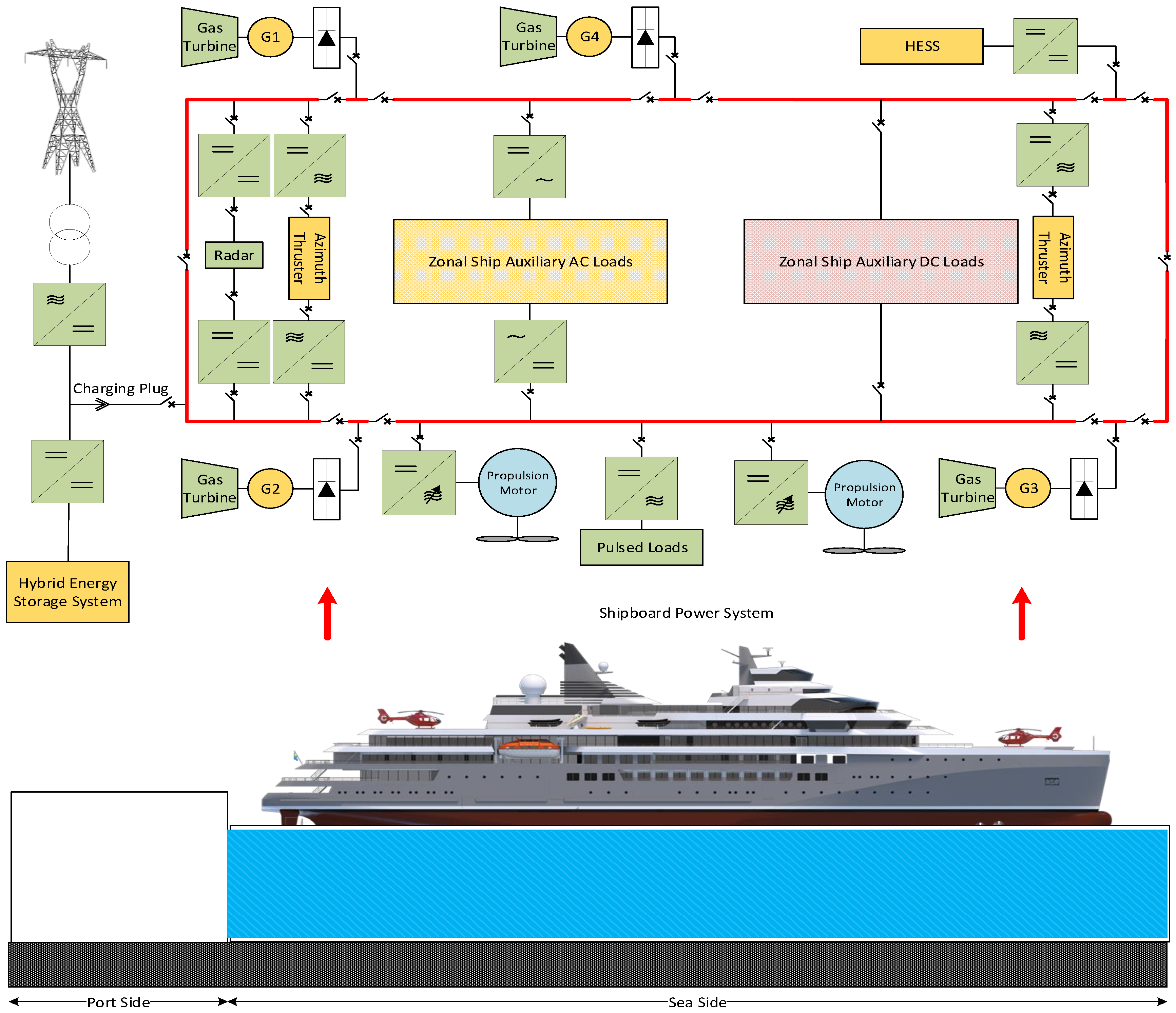
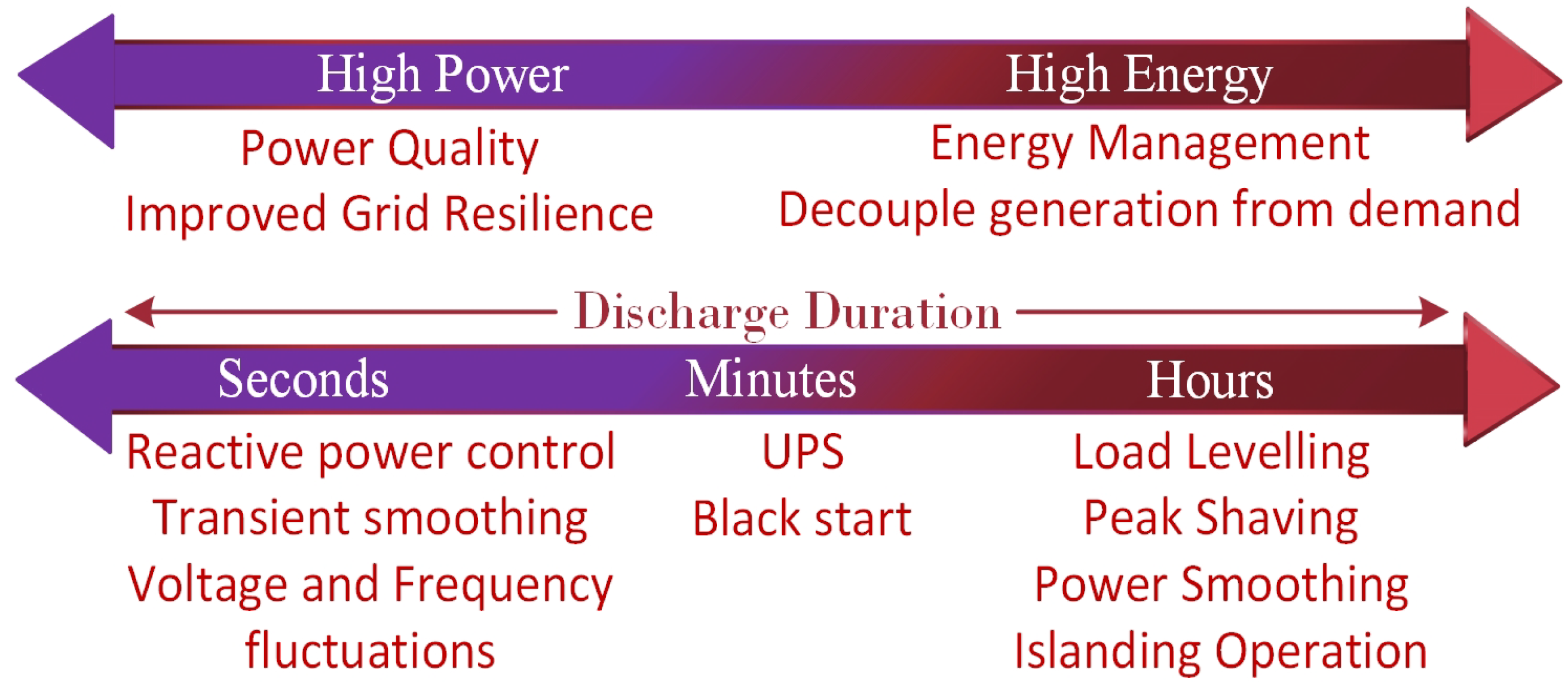
13]. Therefore, HESS is found out to be a promising solution to cater to transients in shipboard power systems in an effective and efficient manner. Lately, mostly ESS is being used as an emergency power supply in the shipboard power systems. It can be helpful especially for offshore vessels in a dynamic positioning (DP) operation where the occurrence of faults may leads to the blackout, hence, in this scenario, ESS can power the propulsion systems for a shorter duration and can reposition the vessel during the fault until the ship is re-powered. Thus, there is a greater possibility of using HESS in future shipboard power systems as a power generation source for load levelling, peak shaving, and for reducing voltage and frequency deviations, which consequently may contribute in enhancing the power quality of the electrical power system.
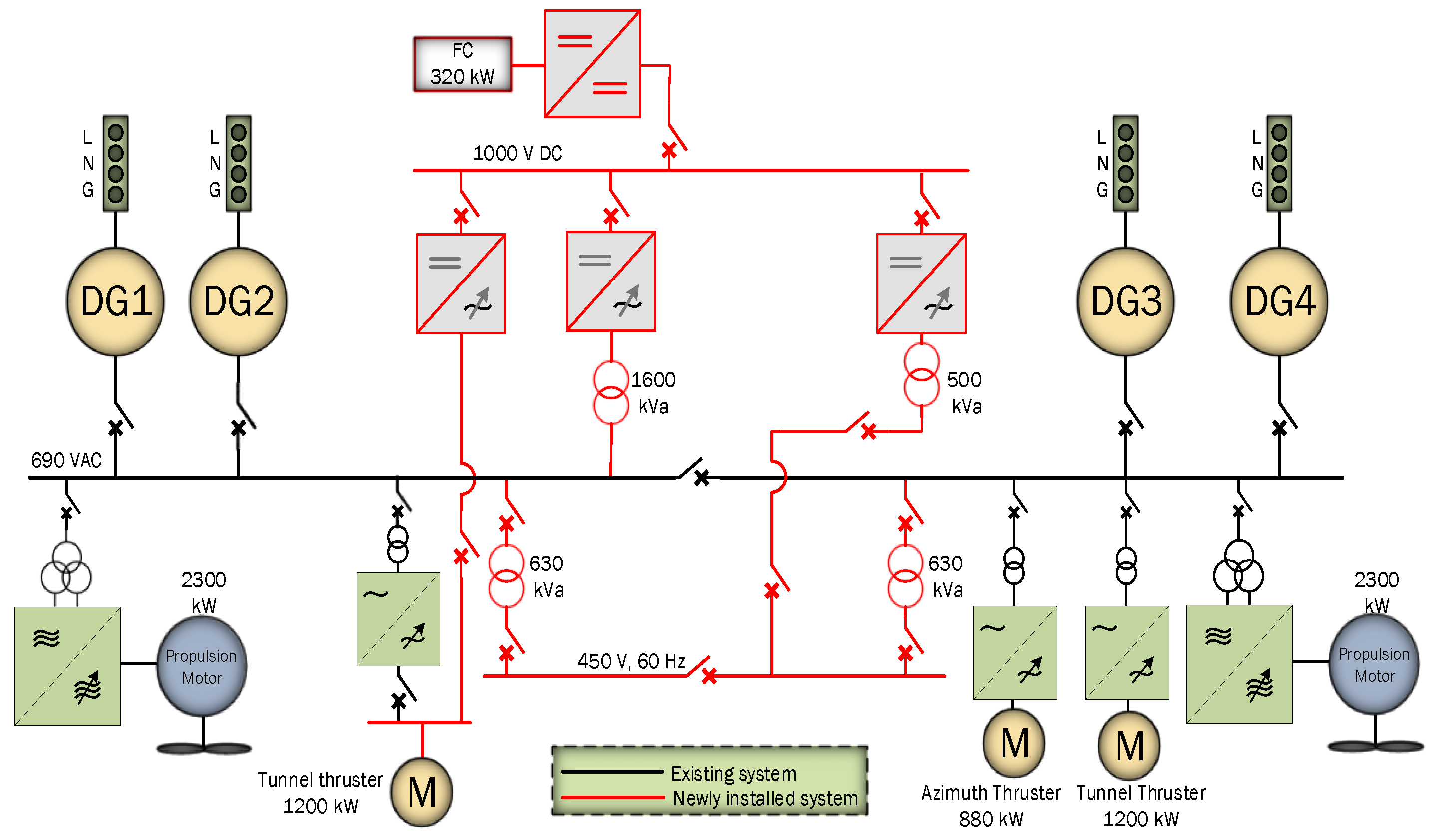
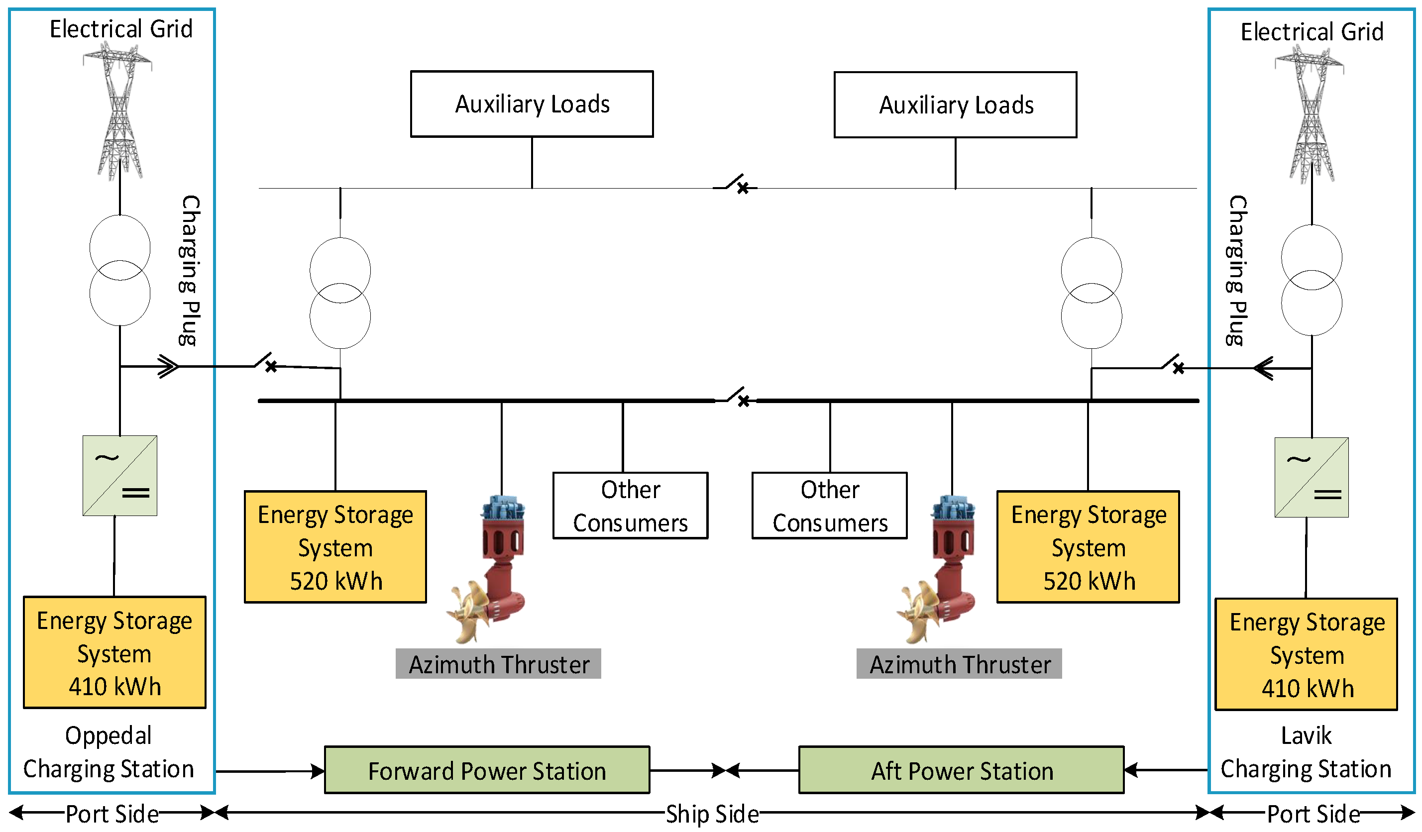
Figure 2 shows future shipboard zonal power system with an integration of HESS.
The aim of this paper is to critically review
Different types of energy storage devices such as batteries (lead-acid, Nickel Cadmium, Sodium Sulphur, Lithium ion), Ultra-capacitors, Flywheel, Superconducting Magnetic Energy Storage, and Fuel cells
The energy storage devices that have already been used in marine vessels
The most used hybrid combinations such as Battery-Ultracapacitors, Battery-SMES, Battery-Flywheel, and Battery-Fuel cell
How the energy storage devices can enhance shipboard power systems
What are the key challenges of integrating the ESS into the shipboard power systems
The rest of the paper is organized as follows:
Section 2 presents an overview of different energy storage technologies. In
Section 3, comprehensive analysis of the hybrid energy storage system are presented. Energy storage applications in shipboard power systems are discussed in
Section 4. The challenges which occur while integrating an energy storage system in shipboard power systems are elaborated in
Section 5. Finally, conclusion drawn from the study and authors opinion are presented in
Section 6.
2. Energy Storage Technologies
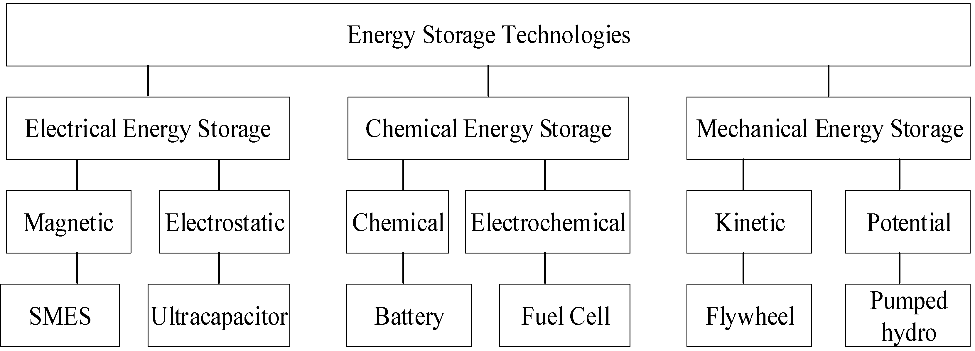
An energy storage system comprises of an energy storage device, conversion of power and its control. Energy storage devices consist of secondary batteries, flywheels, capacitors, Superconducting Magnetic Energy Storage (SMES) systems, Fuel Cells (FCs), and pumped hydro. These devices differ from each other in terms of charge and discharge rate, life cycle, energy and power density, efficiency, etc. They are generally categorized into three groups with regard to the type of stored energy, i.e., electrical, chemical, and mechanical energy storage as shown in
Figure 3.
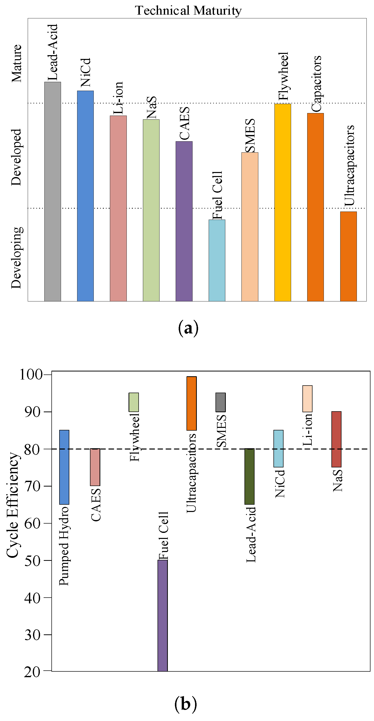
The maturity of different energy storage systems are depicted in
Figure 4a, which are divided into three categories, mature, developed, and developing technologies. Lead-Acid is a mature technology, which has been used for over 100 years. NiCd, NaS, flywheel, ultra-capacitor, and SMES are the developed technologies that are commercially available. However, up till now, they are not used for large-scaled utility purposes. The fuel cell is still in the development phase as storing hydrogen is the key issue in this technology. The cycle efficiency of ESS is defined as
=
where
and
is the output and input energy respectively. The efficiency of different energy storage technologies is depicted in
Figure 4b, which shows that flywheel, SMES, and ultra-capacitor are highly efficient technologies.
2.1. Batteries
Batteries are devices that transform chemical energy directly into electrical energy through an electrochemical oxidation-reduction reaction, and they are categorized as primary and secondary types of batteries. The former one cannot be charged electrically whereas the latter can. Lead acid battery is the most commonly used battery in the market. They are used in Uninterruptible power supply (UPS) [
17,
18,
19,
20], automobiles [
21,
22,
23], etc. The increase in energy and power demands particularly, from hybrid electric vehicles results in large demand of batteries that are capable to produce higher energy density than lead-acid battery. The batteries that can provide an improved energy and power density are nickel metal hydride (NiMH) and lithium ion (Li-ion). Although their cost is high, still they are commercially adopted in various application, mainly in the automobile industry, cameras, medical instruments and in mobile phones.
Table 1 shows the different type of energy storage system with their power density, energy density, cost, efficiency, and lifetime, whereas
Table 2 compares different type of energy storage technologies suitable for marine vessels. It can be seen that batteries such as lead acid, NiCd, NaS, and Li-ion are higher energy density devices, while flywheel, ultra-capacitor, and SMES are higher power density devices.
2.1.1. Lead Acid
Lead acid batteries are the most used batteries in the world since 1890s [
26] and are still extensively used in cost-sensitive applications where limited life cycle and less energy density are not of greater concern [
27]. Their application includes stand-alone system with photovoltaic (PV) [
28], emergency power supply system [
29], mitigating output fluctuations from wind power systems [
30], and as a starter batteries in transportation such as in vehicles [
31]. They have small daily self discharge rate, typically less than 0.3%, fast response time, low capital cost, and relatively high cycle efficiency. The cycle life is around 1500 cycles at 80% discharge depth and the efficiency ranges between 80 to 90% . Furthermore, lead-acid battery is a mature technology, available at lower cost, easy recyclability, and simpler charging technique [
32]. However, the drawbacks of this type of battery lies in lower energy density and using lead (a hazardous material). Moreover, it is not suitable for discharges over 20% of its rated value as it further reduces the life cycle.
2.1.2. Nickel Cadmium
Nickel Cadmium (NiCd) batteries have been commercially in use since 1915s. The battery uses metallic cadmium at the negative electrode and nickel oxyhydroxide at the positive electrode. It has a greater number of cycles, higher power and energy density as compared to lead-acid batteries. The lifetime of NiCd batteries at deep discharge range from 1500 to 3000 cycles depends on the type of the used plate [
33]. This type of batteries are featured by the ability of working even at a lower temperature ranging from −20
C to −40
C. Moreover, these batteries are currently implemented only in stationary applications, which is prohibited in Europe on consumer use due to the toxicity of Cadmium and higher cost [
34]. The best performance is achieved when discharged between 20% to 50% of the rated value [
35].
2.1.3. Sodium Sulphur
Sodum Sulphur (NaS) batteries consist of liquid sodium at the negative electrode and liquid sulphur at the positive electrode, in between these two materials there is beta aluminium tube acting as an electrolyte. The cycle life of NaS batteries is 4500 cycles which is a bit higher than lead-acid batteries and the efficiency is around 75%. It is being particularly used in Japan over 200 sites for peak shaving. The temperature of this battery is kept in range of 300 C to 350 C. In order to maintain this temperature within that range, a heat source is needed so that their performance can be improved using its own mechanism, which results in affecting their performance.
2.1.4. Lithium Ion
Lithium-ion batteries in recent times have been of greater importance since the start of 2000, particularly in the area of mobile and portable applications such as laptops, cell phones, and electric cars. It has been proved that these batteries have exceptional performance especially in medical devices and portable electronics [
36]. The nominal voltage level of each cell is around 3.7 volts as compared to 1.2 volts in the case of NiCd batteries. Another advantage is its higher energy and power density as compared to NiCd and lead-acid batteries. The main obstacle in using it, is the high cost, which is more than 600
$/kWh due to the overcharge protection and its specific packaging. Moreover, the efficiency of these batteries are quite high usually in the range of 95–98%, and the cycle life is around 5000. Safety is another severe issue in Li-ion batteries as most of metal oxide electrodes are unstable and may decompose at elevated temperature. Hence, in order to cater to this situation, the batteries are equipped with a monetizing unit such that to avoid over-discharging and over-charging.
2.2. Ultra-Capacitors
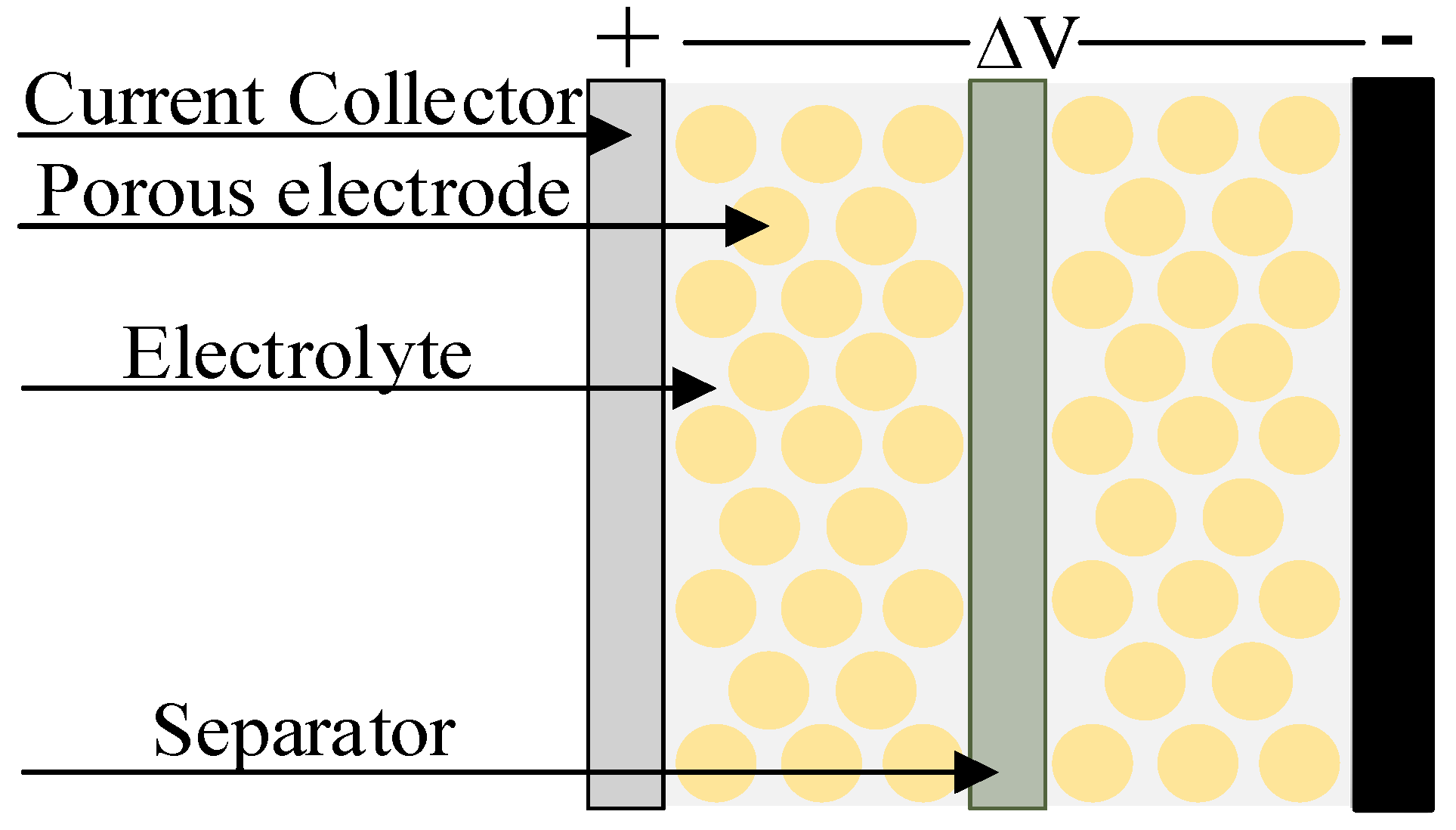
Capacitors store energy in terms of an electric field and generally known for their high symmetrical charge and discharge rates. Usually, capacitors have a quite low equivalent series resistances that enable them to supply the power efficiently. They are generally used in those applications where higher power is required for the shorter duration of time. The applications include camera flashes, filters, and compensation of reactive power. Capacitors are generally categorized by their dielectric medium, electrode material. They are further categorized as super-capacitors (also known as ultra-capacitors), electrolytic capacitors, and electrostatic capacitors.
Figure 5 illustrates the individual structure of an ultra-capacitor. The key characteristics of ultra-capacitors are higher power density, faster charging and discharging due to lower internal resistance, enhanced life cycle, low voltage, and higher cost per Watt-hour (up to 20 times compared to Li-ion batteries). One of the main drawbacks of these ESSs is high sensitivity to over-voltage and, thus, overcharging. The other drawbacks include relatively low energy density, linear discharge voltage, high self discharge, and low cell voltage.
The life cycle of the battery is quite low in terms of charging and discharging cycles. Hence, in order to increase the lifetime of the battery and in particular to preserve system voltage above the minimum threshold, ultra-capacitors are hybridized with batteries in hybrid vehicles [
37,
38,
39]. The use of hybrid electric vehicles comprises of batteries and ultra-capacitors are suggested in [
40,
41] and a commercially available ultra-capacitor based electric bus developed by Sinautec Automobile technologies [
42], the range is around 5.5 miles. The studies have proved that by hybridizing battery and ultra-capacitor results in improving the lifetime, performance, and cycle life of the battery for hybrid vehicles.
2.3. Flywheel
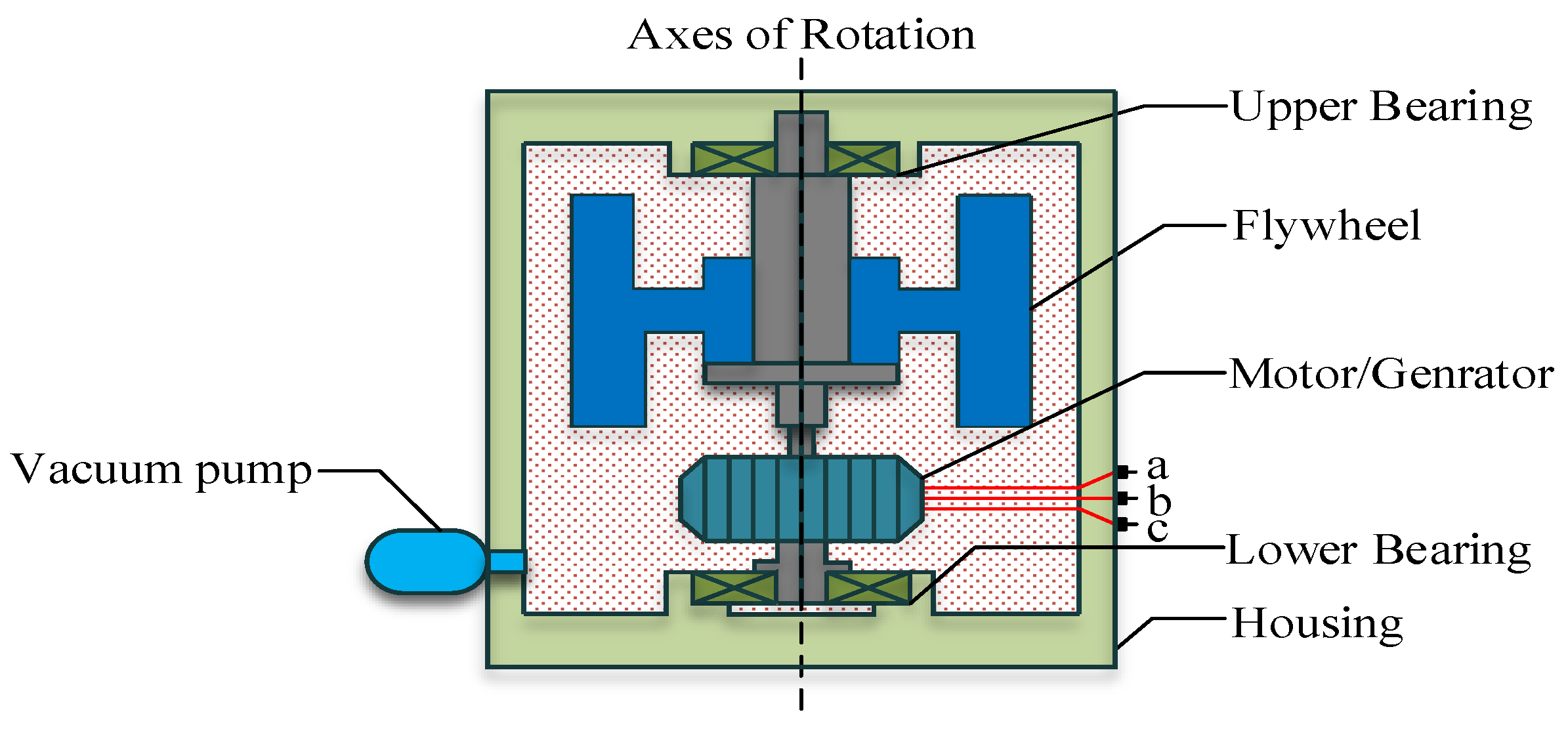
Flywheel stores energy in terms of kinetic energy in rotating mass or rotor. The measure of energy stored depends on rotor mass, location of the mass, and rotor’s rotational speed. In case of a certain amount of energy is stored in a flywheel, this could lead to an accelerating torque, which consequently results a flywheel to speed up. Moreover, when the energy is provided it could lead to decelerating torque, which might results in slowing down the flywheel. The energy stored
E in a high-speed flywheel is given by:
where
I = ∫
(kg·m
) denotes the moment of inertia of flywheel rotor and
(rad/s) is the angular speed of the flywheel. The basic layout of flywheel is shown in
Figure 6. In order to transform rotational kinetic energy to electrical energy, a flywheel must include a generator and motor. Likewise capacitors, the flywheel may have charge and discharge rates equal. They can be useful in improving power quality, peak shaving, power factor correction, and load leveling. Flywheels have been used widely in different applications such as UPS [
43], frequency response [
44], smoothing wind power [
45], and heavy haul locomotives [
46]. As compared to ultra-capacitors, flywheel provides intermediate characteristics in terms of power and energy density. Flywheel technology caters with many shortcomings of prior energy storage technologies by having limited temperature sensitivity, chemical hazardless, the similar rate of charge and discharge cycle, higher life cycle, reduced space, and weight.
The study in [
47] investigated and developed Flywheel energy storage system (FESS) for shipboard zonal power system. The main aim was to know where ESS can improve operation and/or reduce the maintenance cost. The applications where ESS can be beneficial includes “dark” start capability, system stability, pulse weapons, uninterruptible power supply, and load levelling. J. McGroarty et al. focuses “dark” start capability as an application of FESS in order to provide enough power capability and start opportunities to allow and help a gas turbine engine to come online from an off state. The optimization model for optimal sizing of FESS and dispatching controllable units economically for a drill-ship power system is presented in [
48]. An optimization model of power management is proposed such that the optimization cost of vessel is minimized considering operational and technical parameters should not be violated. The proposed method further addresses how much flywheel energy storage system required to be installed and scheduling of various power plants considering several mission profiles and loading levels.
In the future, due to the increase size of all-electric ships there will be large amount of power sharing among different high power loads. In order to evaluate it, a model of a power train has been developed and is implemented in [
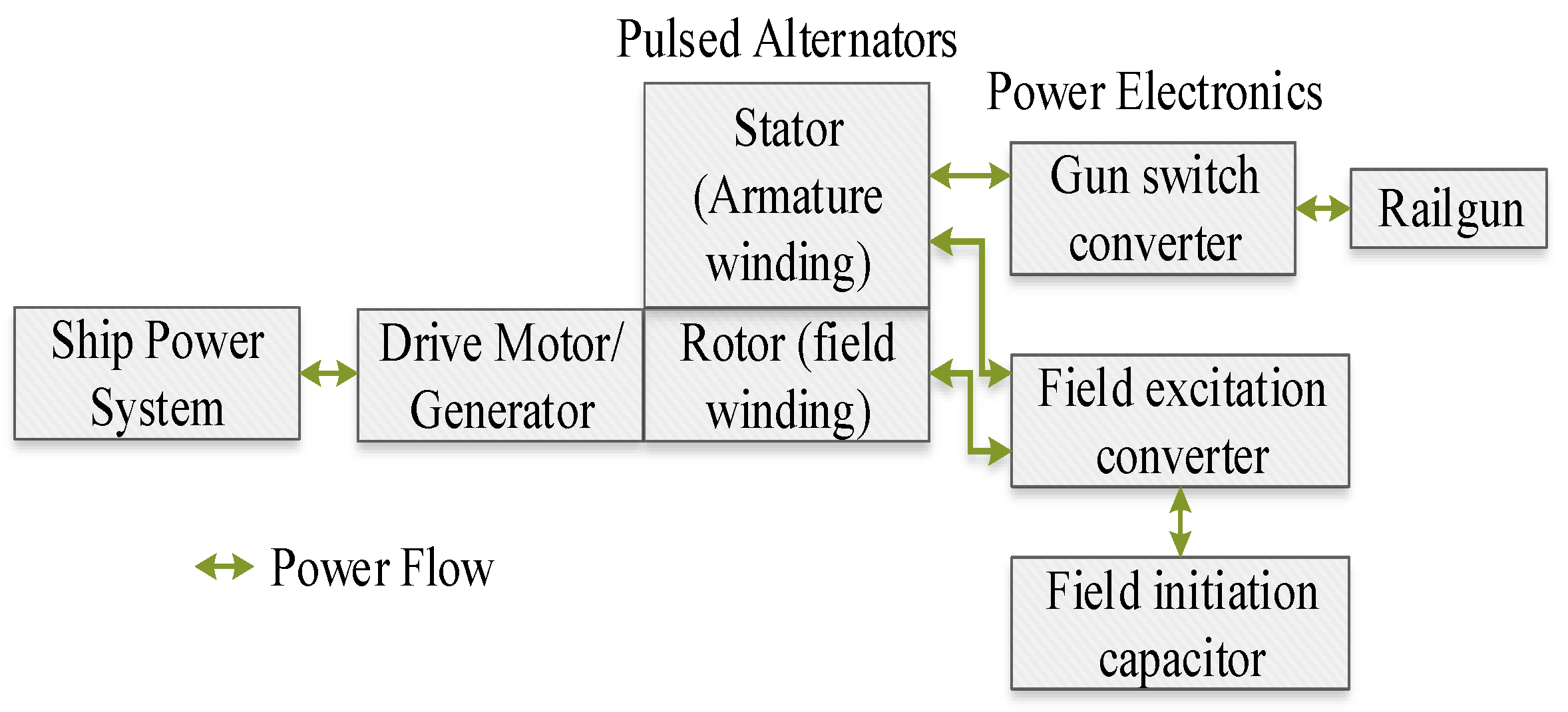
49] for an electric ship. By using this model, the behavior of rotating machine power source have been explored in three different ways for a shipboard rail-launcher. Firstly, the impact of rapid charging of rotating machine on the shipboard power system is discussed by charging the rail launcher through 5 MW motors. Due to this, there would be a voltage sag that can be managed using stored energy in rotating machine (conceptually a FESS) to an appropriate level. Secondly, stored energy in the rotating machine is then used to improve the power quality of shipboard power system. In this study, by using an appropriate power electronics, the stored energy in the rail launcher can be used to correct the power quality issues introduced by rest of ship’s power system. Finally, the energy stored in rotor of an alternator can be used to power a free electron laser for ship’s defense. The rail-gun’s power system is shown in
Figure 7; the prime mover for the system is mainly fed from the ship’s main power grid. The drive motor uses the power from the power grid in order to accelerate the rotor, which results into an energy storage in the rotating mass. Conceptually at this instant, system is having active components similar to a FESS. The stored energy is then used to launch the rail gun instead of using it elsewhere in ship. A capacitor is then discharged via rotor winding and to bootstrap the system to its full power, the induced current in the stator is fed back to the rotor, it takes around 30 ms. After achieving full power, the alternator launches the rail-gun. The pulsed alternator systems have low impendence field windings that rely on positive feedback self excitation or boot-strapping action in order to energize the field winding. So, a capacitor is used for the self-excitation process, which is discharged directly into the field winding. Furthermore, the field initiation capacitor is recharged through ship’s main power system by a bi-directional converter.
The study in [
50] addresses the use of high power FESS for DDG51 Arleigh Burke class destroyers to deal with high-power loads and to minimize the consumption of fuel. In the case of failure on one generator side, energy storage is responsible to power the critical loads up till another generator starts. The proposed study can mitigate transients in the system and provides a ride-through up to 10 min in order to start the backup generator. The study in [
51] simulated FESS on the electrical power system based on offshore plants, which contains DP system such that to prevent from blackout, improve fuel efficiency, and mitigate voltage sags that usually take place in case of fault or the pulse loads. In the scenario, when there is an outage event of generator failure, the FESS will provide power until a backup generator starts. There are some particular rules specified for DP class, i.e., when the generator is operating at no load condition, at a nominal voltage level, and suddenly there is an additional loading, in this scenario the instantaneous voltage drop across the terminals of the generator should not be more than 15% of the nominal voltage. Furthermore, variations in the frequency should not exceed ±10% of the rated frequency and must be recovered within 5 seconds when the step load is turned off. It is observed that by the use of FESS, the power system will overcome frequency drop and voltage sag within the limits to refrain from tripping other generators or blackout of power system. In [
52], FESS is applied on the electrical network at the shipyard for powering the vessels from the shore distribution system such that to minimize fuel consumption on engines, avoid from blackout, and mitigate voltage sags. The simulation results show that there is around 15% drop in the rated voltage by the start of 2.25 HP motor in case when FESS is not integrated. On the other hand, by integrating FESS the voltage drop reduced to 4%.
2.4. Superconducting Magnetic Energy Storage (SMES)
Energy stored in SMES is in the form of a magnetic field created by superconducting coil. Initially, Ferrier introduced it in 1969 and originally it was anticipated as a load-levelling device [
53]. It is an energy storage method based on the fact that current will remain flowing through a superconductor even after the removal of voltage across it because of zero resistance [
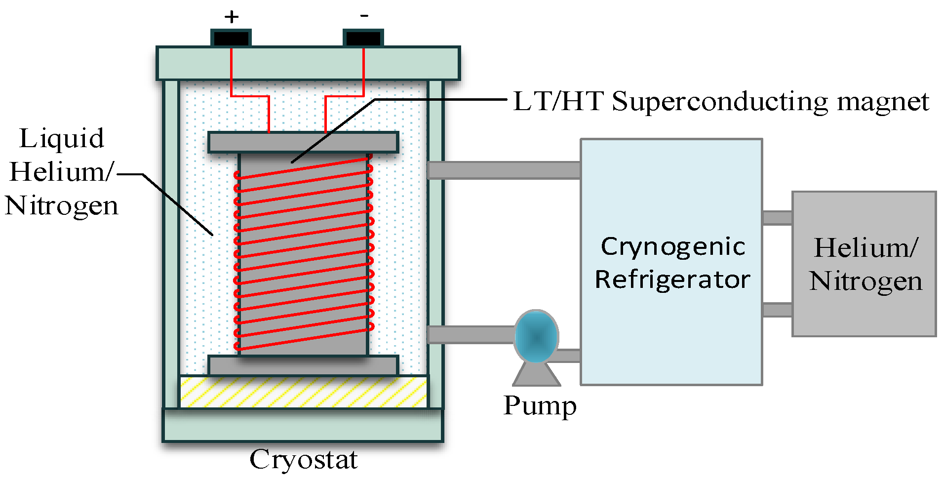
54]. In order to have negligible or zero resistance, the superconducting coil is sustained below the critical superconducting temperature with the use of an external cooling pump. The stored energy in the superconducting coil can then be released by discharging the coil. SMES storage devices are found to be highly efficient, i.e., greater than 95% as compared to other energy storage devices. The power electronic interfaces are needed that produces 2–3% loss in either direction. It has tiny deterioration because of cycling however, it has a high rate of self-discharge because of mechanical stability issues and energy spent on cooling it with cryogenic liquid. The magnetic energy stored in a conducting coil is given by:
where
L is the inductance and
I is the current. SMES system consist of three main components that are a super conducting coil, a cryostat system, and a power conversion system [
55] as shown in
Figure 8. Us Navy is trying to pull out from a stage dominated with hydraulic, pneumatic, and mechanical-based devices to a stage governed by electromechanical-based devices and with full electric control [
56]. Future naval electric weapons require higher power pulses of electrical energy [
57]. It is predicted that 200 MJ pulse forming network is necessary for the Navy’s railgun to attain the anticipated muzzle energy of 63 MJ
[
58]. SMES is found to be an attractive technology for this application, as it exhibits high energy density, zero resistance, and an efficient stored medium. SMES can further be helpful in providing power for onboard submarines, ships, and for naval applications [
59].
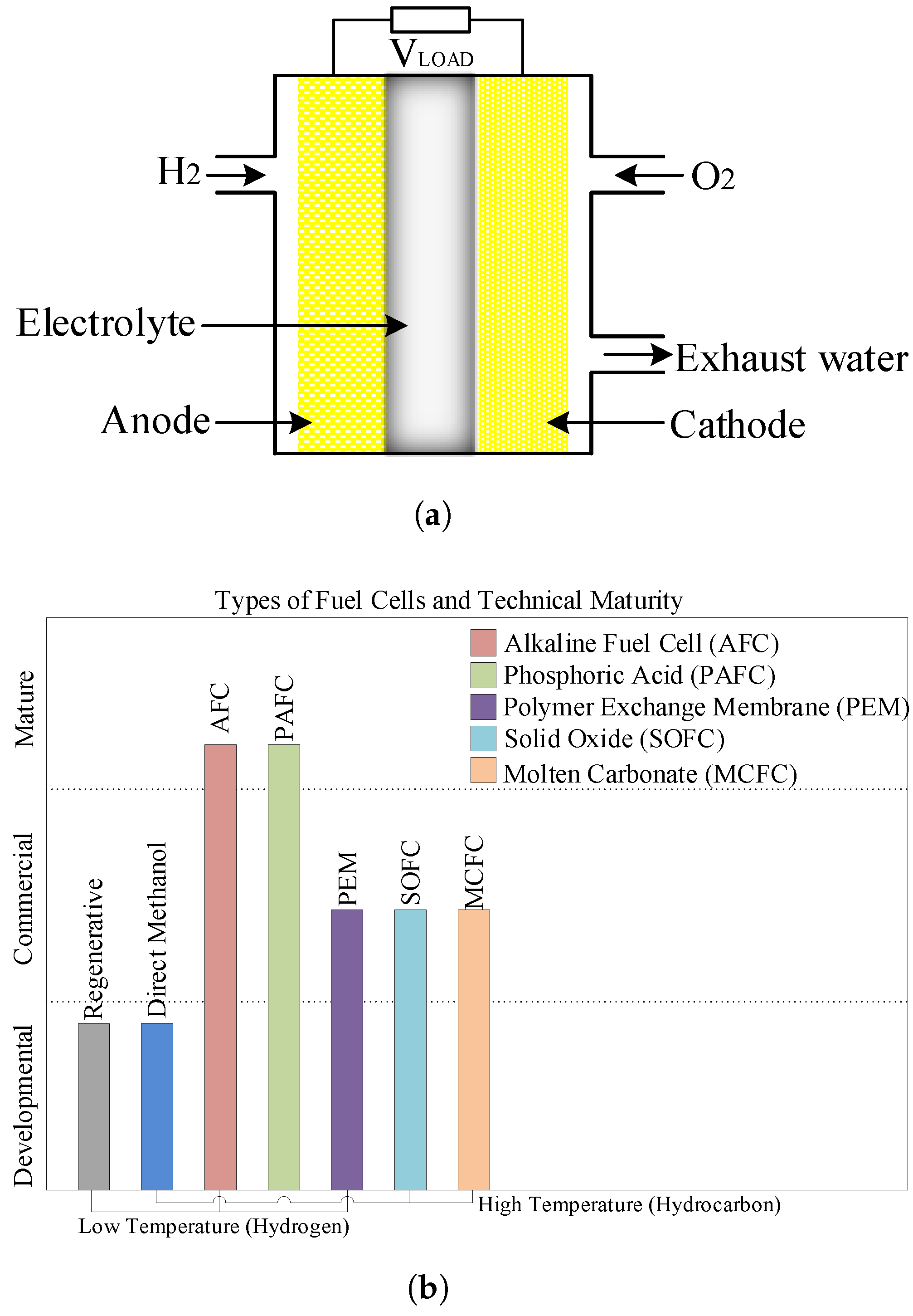
2.5. Fuel Cell
Fuel cell transforms chemical energy directly into electrical energy and have the capability to be an alternative technology to the diesel engine, the individual structure of fuel cell is shown in
Figure 9a. It has been proved to be more efficient as it produces lower or zero-emissions and functions cleaner as compared to a traditional gas turbine and an internal combustion engine. Polymer exchange membrane (PEM) fuel cell has been used to power Howaldtswerke-Deutsche Werft (HDW) submarines. Nine Siemens PEM-based fuel cells were installed for propulsion purposes [
60] ranging from 30–40 kW each. The first passenger ship to use fuel cell based propulsion is FCS Alsterwasser. The goal of the project was to test a ship that is free from emissions and to encourage the use of it for maritime applications [
61]. The storage and hydrogen fuel distribution are the main challenging features for its wider use. As there are severe challenges to store hydrogen at a comparable energy density to hydrocarbon fuels such as liquid natural gas (LNG) or Marine Diesel Oil (MDO) [
62]. It was suggested by Carlton et al. [
63] that the technologies such as Molten Carbonate Fuel Cell (MCFC) and Solid Oxide Fuel Cell (SOFC) will be more favorable for ship propulsion as they use hydrocarbon fuels. The US energy department enlists several types of fuel cell [
64] technology and are categorized as depicted in
Figure 9b.
Fuel cell for low emission ships (FellowSHIP), a research and development project with an involvement of industrial partners that comprises of Det Norske Veritas (DNV) (for the classification rules), Wärtsilä (for the energy), and Eidesvik Offshore (ship provider). The project is funded by Research council of Norway and its main goal was to integrate FC on offshore platforms and on-board vessels. In this research based project, a 330 kW FC is integrated with the
Viking Lady as exhibited in
Figure 10, an offshore supply vessel (OSV), the only commercially available vessel that uses fuel cell technology. It was docked in Copenhagen at the end of 2009 in order to replace traditional machinery to integrate fuel cell technology. The vessel is powered with dual fuel, i.e., liquified natural gas (LNG) and diesel-electric power plant. Four Wartsila based diesel engines and four main generators are installed to power the propulsion system and service loads. The vessel further uses molten carbonated based fuel cell and LNG to meet all the power needs. The Molten Carbonate Fuel Cell (MCFC) generates approximately 320 kW power and is operated around 650
C. Hence, the combined use of gas engine and fuel cell results in the reduction of nitrogen oxide, sulphur oxide, and carbon dioxide emissions [
65], and the efficiency of FC generated electric power was found to be 52.1% [
66]. The concept study based projects that used fuel cell in the shipboard microgrids is enlisted in
Table 3.
3. Hybrid Energy Storage System (HESS)
The Hybrid Energy Storage System (HESS) is a combination of dissimilar energy storage technologies that have different characteristics with regard to energy capacity, cycle life, charging and discharging rates, energy and power density, response rate, shelf life, and so on.
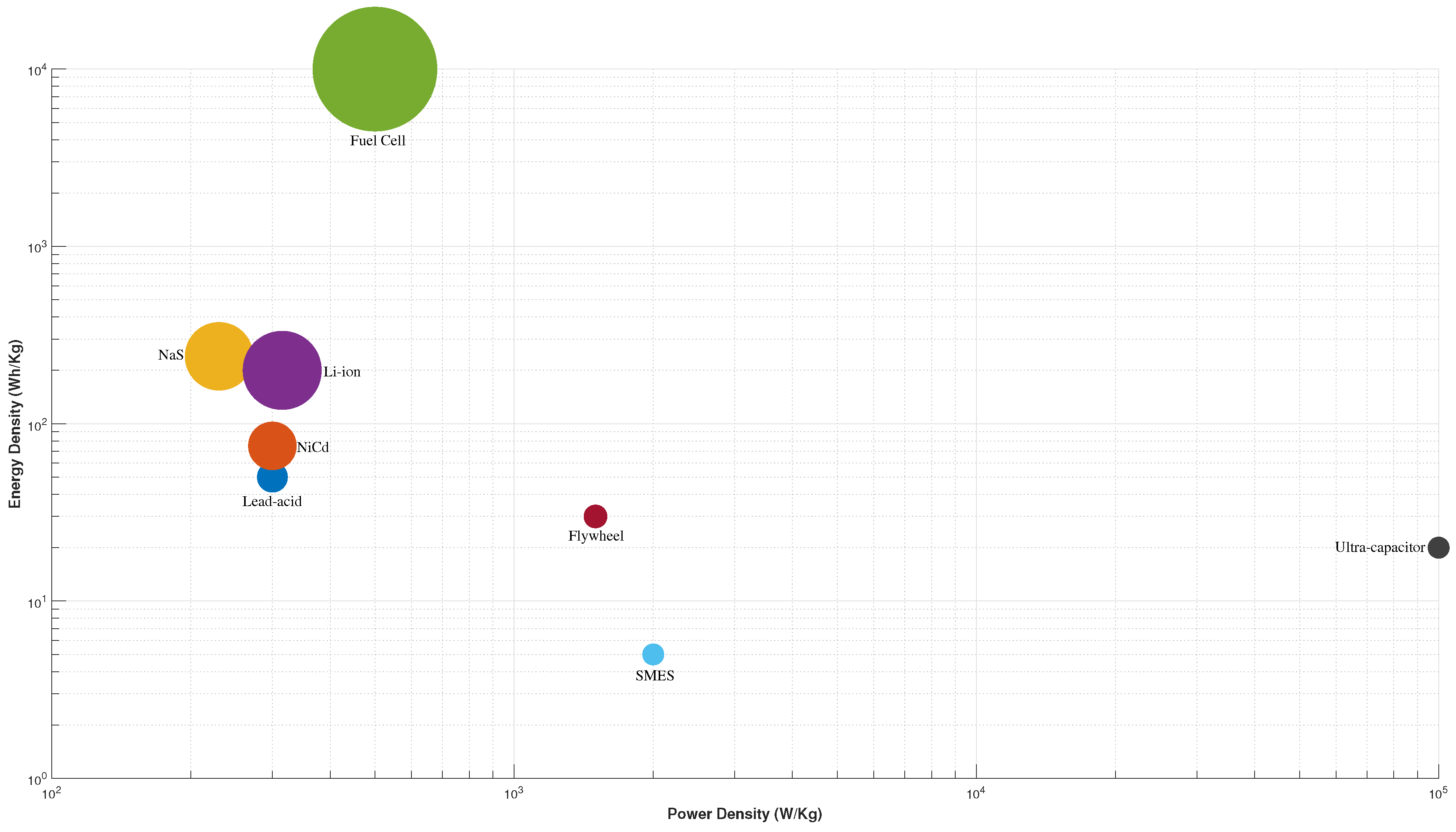
Figure 11 depicts the comparison of energy density, power density and their cost (
$/kW).
ESS technologies can be categorized further into higher energy and power technologies. Higher energy devices such as a battery, fuel cell, pumped hydro, and CAES can supply energy for the longer duration of time but their power is low. On the other hand, higher power devices such as a flywheel, super-capacitor, SMES, and higher power batteries can supply very high power but for a shorter duration of time. It is observed that battery technology can be employed in both categories due to their wide characteristics range. Hence, hybridization of higher energy density devices with higher power density device will yield to a better ESS. In this way, high-energy devices will provide long-term power needs, whereas higher power devices will cater with short duration but higher power needs. Based on the above discussion, the possible combinations, which are extensively used in literature for different applications are depicted in
Table 4.
3.1. Battery-Ultracapacitor
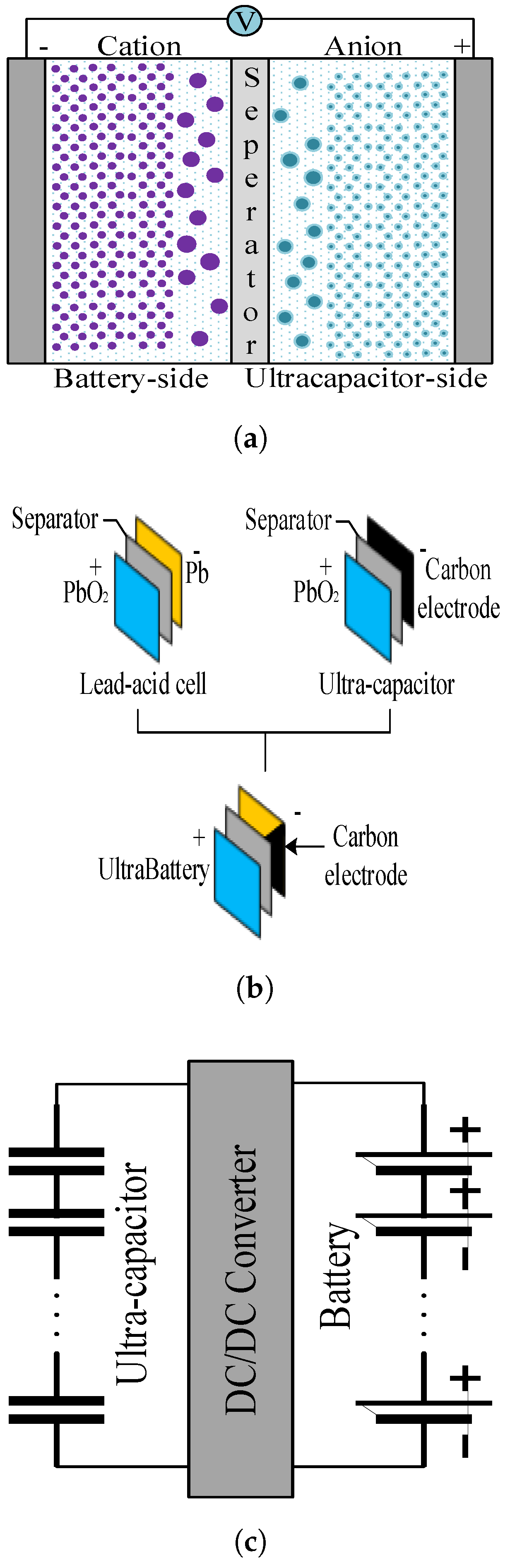
Among all hybridized technologies, hybridization of ultra-capacitor and battery has been proposed in literature quite extensively. The rechargeable batteries are generally with high energy density and low power density normally below 1 kW/kg. The life cycle of the battery is quite low ranging from 1500 to 4500 cycles as compared to ultra-capacitors. In some literature, ultra-capacitors are named as supercapacitors and electrochemical double layer capacitors as well. This energy storage device has low energy density, typically below 10 kWh/kg and higher power density typically above 10 kW/kg. Furthermore, it possesses a high life cycle normally above 50,000. Generally, hybridization can be carried out via several methods, which can be categorized as internal and external hybridization [
89]. In case of internal hybridization, the devices are developed by the hybridization of battery and ultra-capacitor on the electrode level as shown in
Figure 12a. The hybrid battery pack system “UltraBattery” [
90] is an example of internal hybridization as shown in
Figure 12b. It is the hybridization of lead-acid battery and ultra-capacitor and was developed by Commonwealth Scientific and Industrial Research Organization (CISRO) in Australia. On the other hand, the hardwire connection between a ready available battery and ultra-capacitor is categorized as “external hybrid” as shown in
Figure 12c. Among the methods mentioned above, the external hybrid method is the extensively used method in several applications.
Yichao tang et al. [
79] explores the feasibility by hybridizing battery and ultra-capacitor energy storage for naval applications. A dual active bridge based topology is proposed to control the bi-directional power flow through phase shifting for both charging and discharging ultra-capacitors and batteries. The topology is designed in such manner that it can meet the requirements of both 1 MW pulsed load and 100 to 500 kW propulsion system. Higher frequency switching devices were selected such that to achieve DC-DC conversion at higher power and voltage levels. The electric propulsion system in vessel experiences large torque and power fluctuations on their drive shaft because of waves and rotational motion of propeller. Jun Hou et al. [
80] explores novel solutions to address such fluctuations by exploring energy management strategies and integration of ultra-capacitor and battery. The two main objectives, i.e., mitigation of power fluctuations and HESS loss minimization are assessed at different sea conditions. The simulation results depict that substantial benefits can be attained in terms of reduction in fluctuations and losses. During navigation of ships at sea, it suffers from a constant rocking motion and is affected by ship navigation parameters and surrounding sea conditions, which further increases the uncertainty involved with the use of solar energy in ships. In [
91], a mathematical model is considered for generating power through PV modules while considering both the sea conditions and movement of the ship. The rocking motion of vessels fluctuates the power typically for 10–20 s and it can reduce the lifetime of the battery to quite an extent. Hence, to cater to situation hybridization of ultra-capacitor with lithium-ion battery is proposed to improve the stability and reliability of the power system. The hybrid energy storage system based on ZEBRA batteries and ultra-capacitors modules for All-electric ships were considered in [
92] to decrease the battery charge and discharge peak currents. Ultra-capacitor modules were considered in order to extend the expected life of the battery. Cohen et al. [
93] presented an actively controlled Li-ion battery hybridized with ultra-capacitor for pulsed power applications aiming to maximize the energy density of Li-ion battery and also to maximize the energy and power density of Ultra-capacitor. Furthermore, the authors designed, constructed, and validated the hybrid model using commercial off-the-shelf technologies and it is observed that the generator’s frequency and voltage deviations are massively improved.
3.2. Battery-SMES
The capacitor’s nominal voltage is quite low ranging from 1 to 2.5 V due to the fact that the series connection of numerous units is required in order to provide higher voltages. However, connecting several units together in series can cause voltage imbalance. So, in order to balance the voltage, some protection circuits are required, these interfaces further may cause fluctuations in the power system, hence, step-down and step-up converters are further installed to adjust the output voltage. The change in output voltage in ultra-capacitors varies with its charge and discharge and is proportional to the stored energy. In contrast to ultra-capacitors, superconducting magnetic energy storage (SMES) does not require any step-down or step-up converters. It is basically a superconducting coil that stores energy in the form of a magnetic field. It has the capability to deliver from/to power system with outstanding characteristics such as high efficiency, high power density, fast response time, and higher life cycle. The implementation of SMES system is difficult, as it requires the refrigeration mechanism that is quite costly and involves complex maintenance. The special site requirements further limit its application that is stationary such as railway supply substation and renewable generation sites. Some researchers who proposed and investigated battery-SMES-based HESS system for transportation applications are as follows.
The demand for all-electric ships (AESs) amplified rapidly in recent times and load fluctuations in the system may lead to severe issues such as increased fuel consumption, voltage fluctuation, and environmental emissions. HESS comprising of a battery (higher energy density) and SMES (higher power density) proposed in [
81] in order to cater to shiploads that cause sudden changes such as maneuvering and pulse loads. As the ramp-rate of vessel-generators such as gas-generators usually are in between 30–50 MW/min range and on the other hand, pulsed load require 100 MW/s ramp-rate that is far higher than the ramp-rate of generators [
94]. Hence, ESS has become vital to deliver a huge amount of energy within a short period.
3.3. Battery-Flywheel
Jun Hou et al. [
82] proposed a hybrid battery and flywheel energy storage system in order to isolate load fluctuations from the shipboard power network. The effectiveness and feasibility of the proposed hybrid system to mitigate load fluctuations for all-electric ships under various sea conditions are shown through simulations. Li-ion battery was used due to their higher power and energy densities than other batteries.
In [
83] the authors explored a novel solution by using flywheel and battery as a hybrid model in order to address fluctuations in load power. It is shown through simulations that with the use of battery-flywheel, the effectiveness and feasibility is quite high such that to mitigate load fluctuations, especially at high sea states. As power fluctuations may result into reduction in electrical efficiency, uncertain consumption of power, and most probably affect shipboard power quality. In [
95] flywheels have been analyzed such that to address pulse power loads. The results depict that by using flywheel energy storage system, the stability of shipboard power system can be maintained during operation of pulse load. AT Elsayed et al. [
96] presented a comparative study in order to determine the optimal hybridization of batteries, flywheel, and ultra-capacitors to minimize the frequency and voltage fluctuations, which are produced in a result of adding pulsed loads to the shipboard power system either on the AC or DC side. Hai Lan et al. [
97] modeled a high-speed FESS in order to smooth the photovoltaic power fluctuations and hence improving the power quality of a large oil tanker. The sinusoidal pulse width modulation (SPWM) along with constant torque angle control method is proposed such that to control charging and discharging of a flywheel.
3.4. Battery-Fuel Cell
Hydrogen-based fuel cell presently has been of greater importance in the maritime industry which includes: Nemo H2, Hydrogenesis, Hydra, and fuel cell ship (FCS) Alsterwasser. Reduction in consumption of fuel, lesser emissions, negligible noise, lower maintenance requirements, and minimal vibration are the key features which led in developing maritime fuel cell technology. In 2008, Alster-Touristik GmBH developed FCS Alsterwasser, it was a first passenger tourist vessel that was entirely powered by fuel cells. FCS Alsterwasser can withstand up to 100 passengers operating at cruising speed of 8 knots, it has two 50 kW fuel cells powering 100 kW hybrid electric propulsion system in combination with lead-acid batteries [
48]. Henderson further states that it is estimated that approximately 220 kg of SO
x, 77 tons of CO
2, and 1000 kg of NO
x is saved annually as compared to the traditional diesel-powered vessel. In December 2009, Nemo H2, a zero-emission canal boat was developed by Fuel Cell Boat B.V. It has the capacity of 87 passengers and 1 crew member operating at a cruise speed of 16 km/h. A hybrid propulsion system comprising of 60–70 kW PEM-based fuel cells with 30–50 kW batteries were installed. 24 kg of Hydrogen is stored in 6 cylinders at a pressure of 35 MPa [
68].
The requirements of military submarines are quite severe, such as they longer underwater operation, low transfer of heat to sea water, low magnetic signatures, and low noise levels [
98]. Traditional submarines are equipped with a diesel-electric based propulsion system and for underwater operations, battery energy is used (lead-acid). The batteries were charged using diesel generators during snorkelling period. Hence, fuel cells are found to be a possible alternative candidate in order to meet the specific requirements associated with air-independent propulsion (AIP) system [
99]. In the 1980s, the German navy in collaboration with Siemens has tested 100 kW Alkaline Fuel Cell (AFC) system in an onshore laboratory and then in Class 205 submarine U1 [
98] in order to judge the application of fuel cells for the submarine. The system consists of 16 × 6.2 kW Siemens modules of AFC, four modules each connected in series in order to correspond to battery’s voltage and propulsion system. Later on, Siemens developed a 34 kW Polymer electrolyte fuel cell (PEFCs) module for German Class 212 submarines [
100]. Submarine class 214 was launched in 2005, it uses two Siemens-based 120 kW PEFC modules [
101]. It is connected to the main grid via DC to DC converter and has the efficiency of 56% on full load.
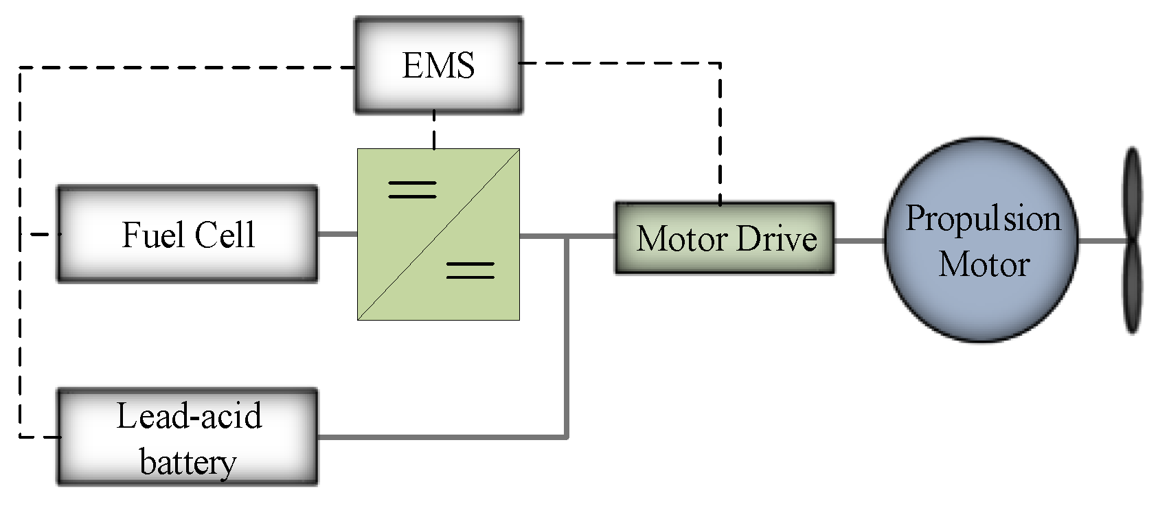
A hybrid fuel cell/diesel generator power system is proposed in [
102] for propulsion and for test equipment on a research vessel. The PEM-based fuel cell system with a battery as backup and secondary energy source simulated in power system computer aided design (PSCAD). The secondary source is a lead-acid battery with a rating of 360 V and energy 82 kWh. The simulation-based analysis depicts that the system has the capability to handle sudden load changes with minimal transients. Although FC’s are a promising solution to reduce greenhouse gas emissions but their response time is not fast enough to cater to load transients that might occur in vessels at sea. Hence, higher density secondary batteries are needed to accomplish stability under transients and usually, dc/dc converters are needed for interfacing battery and FC into the DC link. Alireza et al. [
103] presented an intelligent power strategy in order to improve the performance of FC without utilizing dc/dc interfacing converters. A new FC power management based strategy by using genetic algorithm proposed in [
103] such that to guarantee the efficient performance of FC stack by preserving FC voltage within a required range in FC–battery hybrid system without the use of DC/DC interfacing converters.
The study in [
104] proposed a hybrid system based on battery and PEM-based fuel cell to control power generation in a shipboard power system. The mathematical model for regulating active and reactive power is derived and integrated with PEMFCs in order to enhance the system dynamic response. Test results illustrate that injunction of hydrogen fuel into the fuel cells can be regulated automatically with fluctuations in loads. Furthermore, the batteries are used to compensate power in order to maintain operational security of the system.
5. Challenges of Integrating Energy Storage System in Shipboard Microgrids
Electric ships experience immense propulsion load fluctuations on their drive shaft, particularly due to rotational motion of the propeller and waves, which affect the reliability and can cause wear and tear. Hence, modern shipboard microgrids are needed to be designed while considering challenging performance criteria and also considering the environmental concerns. These requirements demand to improve the design methods for vessels and their operation. The ESS can be considered either as the main source of power or as a redundant power source. In literature, there are several works where energy storage has been utilized in terrestrial microgrids to minimize the effects of changes in loads on the crucial parameters of the system. However, in shipboard microgrids, such approaches are yet to be applied at such level. Recently, control techniques being used are adaptive control, particle swarm optimization, proportional integral (PI) control, active and reactive power (PQ) control, etc. The abrupt changes in shiploads due to dynamic pulse loads such as high-power radars, an electromagnetic rail gun, laser self-defense system, etc., changes the power demand in a quick manner. These issues may reduce the efficiency of the whole power system if properly not handled.
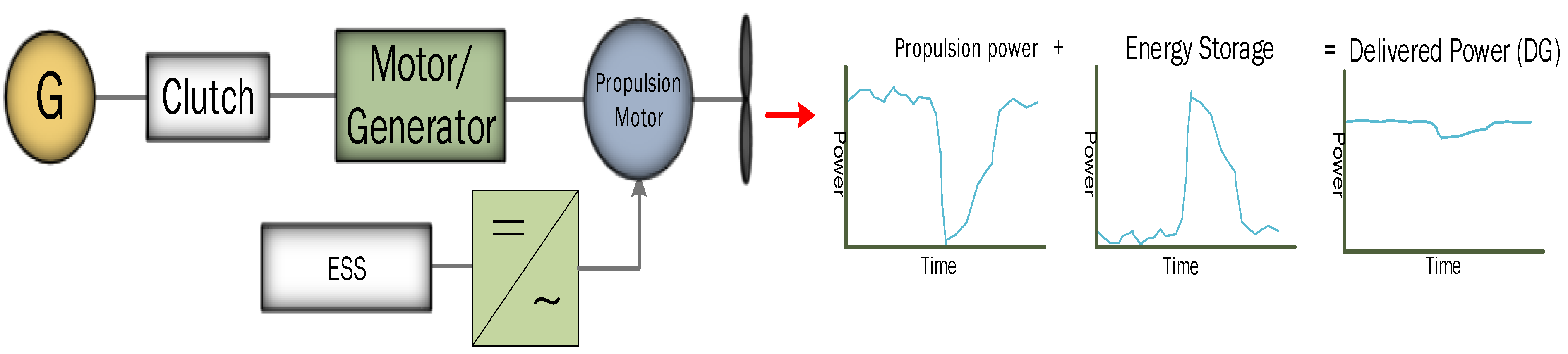
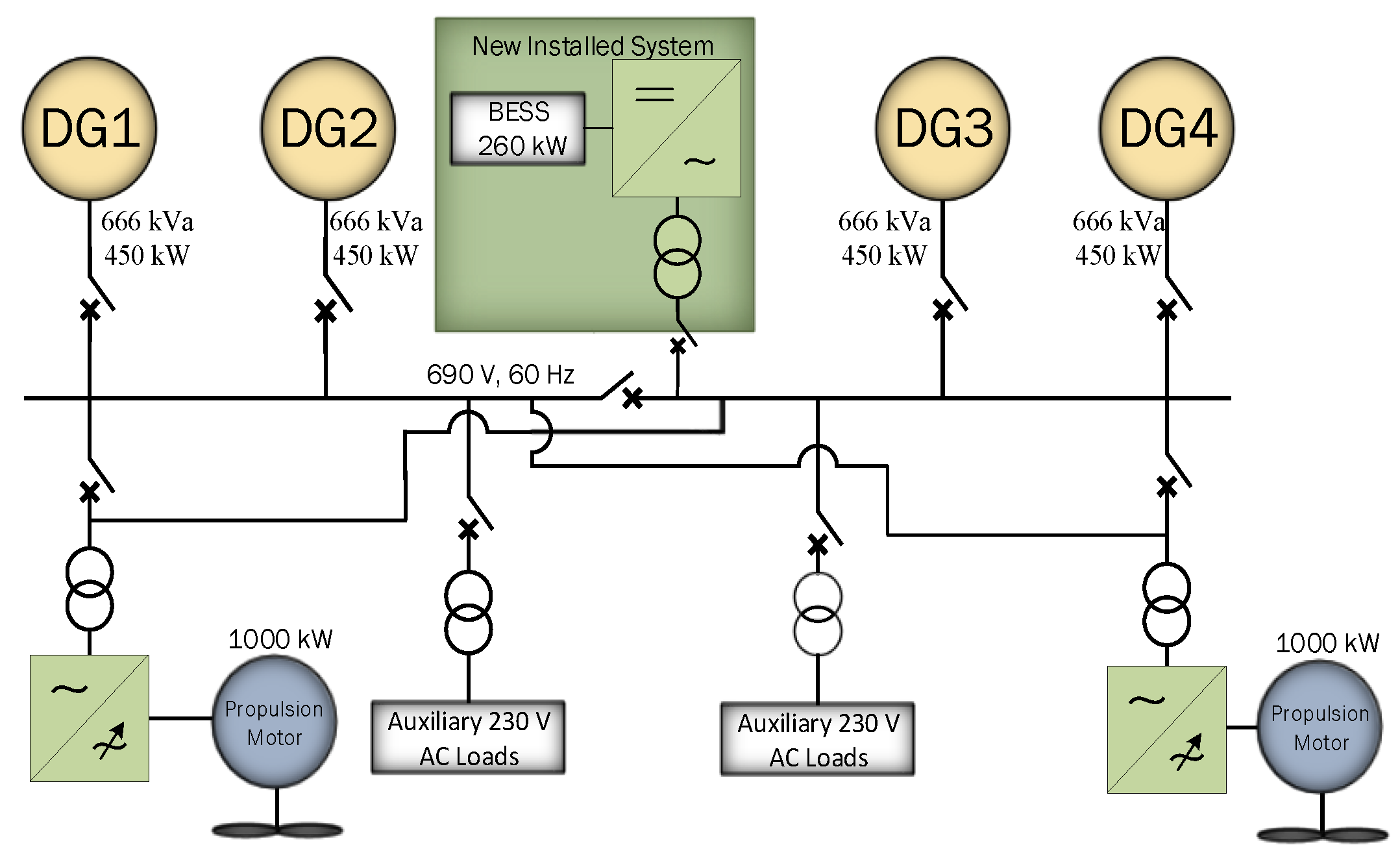
Furthermore, ESS technologies are quite expensive and rely on power conversion devices depending on the power system either AC or DC. In this case, a solution might be to install ESS as part of motor drives as shown in
Figure 17 in order to eliminate the requirement of additional power conversion devices, hence resulting in the reduction in the cost and weight. In this scenario, by installing ESS alongside with an AFE, the ESS can attain application flexibility, therefore can mitigate harmonics, peak shaving, etc. The battery packs are quite heavy and take a lot of space but can replace at least one prime mover from the vessel. The other issue with battery technology includes the lifetime, swift charging and discharging of batteries may result in heat, which further causes a reduction in the lifetime of a battery. Hence, there might be a possibility that batteries may be defected or died before they manage to cover the installation cost by reducing the consumption of fuel. To solve this problem, the involvement of ultra-capacitors, flywheel, fuel cells, etc., can be beneficial. They are installed with the battery packs to improve charge and discharge speed, increase lifetime, enhance power density and so on. In present, using a single energy storage system might not be a solution as batteries can only provide higher energy density whereas flywheel, ultra-capacitor can provide higher power density. Batteries further have a short life cycle as compared to higher power density-based energy sources. Hence, hybridizing two energy storage devices might be an interesting solution for future shipboard microgrids.
6. Conclusions
This paper reviews different hybrid combinations of energy storage systems for shipboard power systems which are applied in the literatures. The possibility of using energy storage systems in load levelling, peak shaving, power smoothing, and power quality improvement are briefly discussed. It is observed that ESS can be useful to flatten the vessel’s load profile, to facilitate starting and stopping of generators, and reduces the number of online prime movers. Therefore, in low loading conditions, the ESS charges and during the high load demands, the ESS provides the stored power and hence discharges. Moreover, it helps the prime movers to run at their optimal fuel-consumption efficient point. ESS in peak shaving applications, further economizes the fuel consumption and therefore results in a reduction of emissions by reducing the number of online generators. Among the batteries, Li-ion is the most used battery for shipboard power applications, specifically for ferries that cruise on shorter routes. Furthermore, it can contribute in reducing the fluctuations caused by the propulsion loads. The hybridization of energy storage devices are expected to provide an extra support in future for larger cargo vessels and for larger routes as well. It is found that battery-flywheel and battery-ultracapacitors energy storage systems have been among the most used energy storage devices, particularly for the applications that are related to shipboard power systems. The hybrid battery-fuel cell is also among the frequently used technologies in literature, but efficiency and storing issues of hydrogen in case of fuel cells is still a major concern.

 ,
, 


