Article

Development of a Multi-Well Pairing System for Groundwater Heat Pump Systems

1
Department of Architectural Engineering, Pusan National University, 2 Busandaehak-ro 63, Geomjeong-gu, Busan 46241, Korea
2
GGK Company Limited, 69-63 Sansu-ro, Chowol-eup, Gwangju-si, Gyeonggi-do 12737, Korea
*
Author to whom correspondence should be addressed.
Energies 2018, 11(12), 3485; https://doi.org/10.3390/en11123485
Submission received: 30 October 2018 / Revised: 5 December 2018 / Accepted: 10 December 2018 / Published: 13 December 2018
(This article belongs to the Special Issue Geothermal Energy: Utilization and Technology 2018)

Abstract

:
Groundwater heat pump systems (GWHPs) can achieve higher coefficient of performance (COP) than air-source heat pump systems by using the relatively stable temperature of groundwater. Among GWHPs, multi-well systems have lower initial investment costs than conventional closed-loop geothermal systems, because they typically require installation of fewer boreholes for the same building load. However, the performance of GWHPs depends significantly on the groundwater properties, such as groundwater temperature, permeability and water quality. Moreover, pumping and injecting of groundwater during long-term operation may lead to problems such as overflow or clogging of the wells. In order to ensure reliable energy from ground sources, the development of sustainable operation methods for multi-well systems is essential for preventing overflow and well clogging. In this study, we have developed a pairing technology that connects the injection and supply wells through a spillway. This pairing technology can be used to control groundwater levels in wells and can be sustainably operated. To accurately estimate the performance of a multi-well system with the proposed pairing technology, the heating and cooling performance of the developed system was compared to that of a standing column well (SCW) system in a field-scale experiment. Furthermore, the effects of the multi-well pairing system on groundwater levels in the injection well were analyzed by numerical simulation. Moreover, in order to decide the required conditions of the multi-well pairing system, case studies were conducted under various hydraulic conductivity and pumping conditions.

Graphical Abstract

1. Introduction

Ground source heat pump systems (GSHPs) are equipment that uses groundwater or heat in the ground as a heat source to deal with the cooling and heating loads of buildings. The ground temperature at 10–15 m below the ground surface is characteristically constant throughout the year [1], therefore, the heat exchange efficiency of a GSHP system is better than that of an air-source heat pump (ASHP) system. GSHP systems are classified as open-loop systems or closed-loop systems according to the heat exchange method. An open-loop system exchanges heat by using the groundwater of an aquifer. On the other hand, a closed-loop system has a closed-loop circuit installed in the ground and exchanges heat using the circulating water inside the circuit. In the case of a closed-loop system, more boreholes are required compared to the open-loop system, and this increases the initial investment cost of the system to deal with a similar load. Rafferty [2] quantitatively analyzed the installation costs of an open-loop system and a closed-loop system. As a result, the drilling cost for a 528 kW capacity building was 80% lower for the open-loop system than the closed-loop system. However, despite of excellent economic efficiency and performance of open-loop systems, the adoption of open-loop systems is lower than that of closed-loop systems. Particularly, the adoption rate of open-loop systems in South Korea is 1/5 of that of closed-loop systems [3].
The main factor that impedes the adoption of open-loop geothermal systems is that it uses groundwater. In the process of directly pumping water, exchanging heat, and discharging the water, there is a large concern about the physical and chemical environment changes in the ground. Therefore, many studies have been performed to solve the problem and increase the adoption of open-loop systems. Zhou et al. [4] performed tests and numerical analysis for GWHP systems and verified the accuracy of numerical analysis modeling. Lo Russo et al. [5,6] carried out studies to develop a thermally affected zone (TAZ) around the injection well of a GWHP system. The impact of TAZ was analyzed by changing the soil parameters, and a sensitivity analysis of the parameters was performed. Kim and Nam [7] developed a system performance estimation method to provide a guideline for GWHP systems. Through the performance analysis according to the groundwater temperature and flow rate, a method was proposed to determine an adequate overall heat transfer coefficient of heat exchanger during design. Al-Habaibeh et al. [8] conducted a study to deal with a building load by applying the mine drainage of an abandoned mine to an open-loop system. Through the performance analysis of this open-loop system using the mine drainage, it was confirmed that the mine drainage temperature and water level were acting as performance factors. Zhen et al. [9] conducted a performance test of a GWHP system and analyzed the difference of energy consumption with a conventional air conditioning system. In the results, the GWHP system had 42% reduced energy consumption compared to the conventional air conditioning system. Park et al. [10,11] analyzed the effect of water injected into an injection well on the geothermal dispersion and the effect of thermal dispersion on the sustainability of a GWHP system. Park et al. [12] investigated the isotopic compositions and chemical of groundwater as the GWHP system was operated to understand its geochemical properties. Bae et al. [13] set the operation and ground as case conditions and quantitatively showed the changes of groundwater level and groundwater temperature according to the operation of a multi-well system. However, when a multi well open-loop system is used for a long term, there is a concern that clogging may occur. If clogging occurs, it will lead to a power consumption increase of the well pump in the supply well and overflowing of groundwater in the injection well.
To solve the clogging problem occurring when a multi-well system is operated for a long period, this study developed a pairing technology whereby a spillway is installed between two wells (supply well and injection well). The pairing technology prevents the overflowing phenomenon of the injection well through the spillway and aims for a long-term operation of the system. In this study, a real-scale experiment was performed for quantitative performance measurement of a multi-well system with pairing. Furthermore, in order to decide the conditions under which the spill-way was required, case studies in various ground and operation conditions were conducted by simulation. In addition, the effect of the spill-way on the groundwater level was analyzed by using pairing under the conditions where overflow occurred.

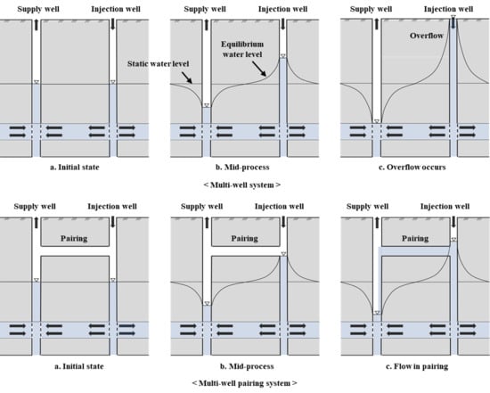
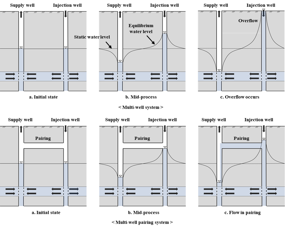
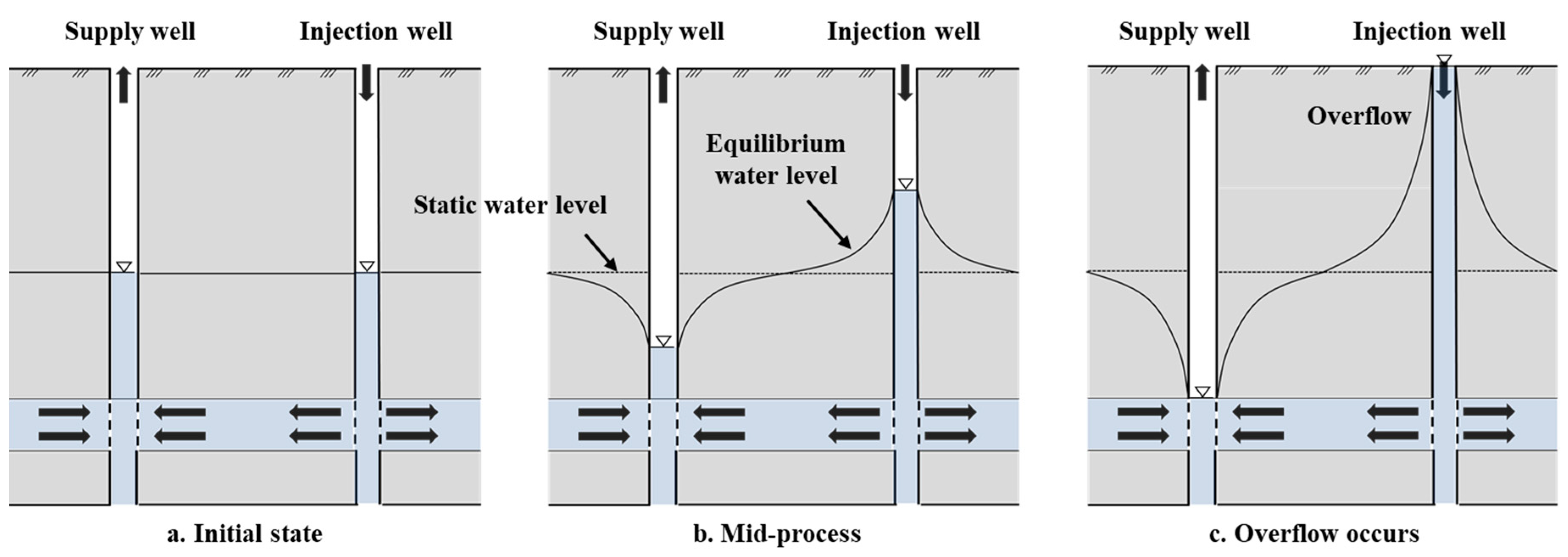
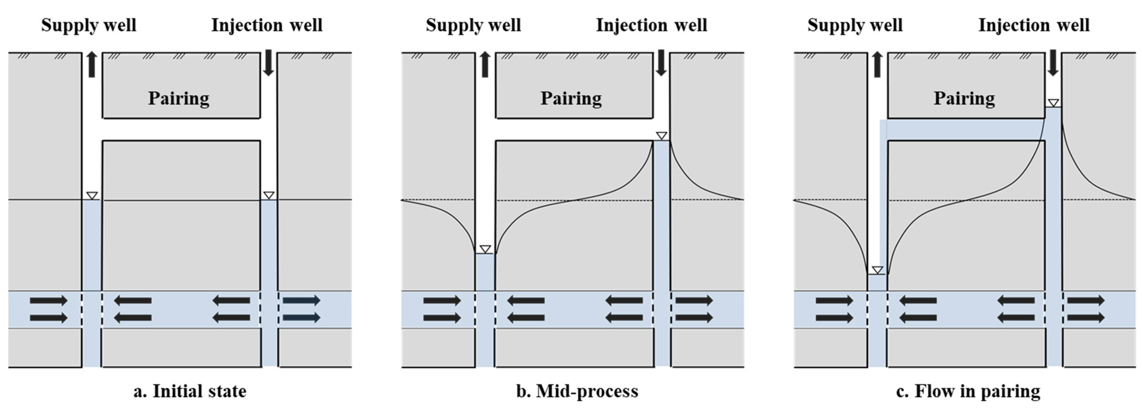
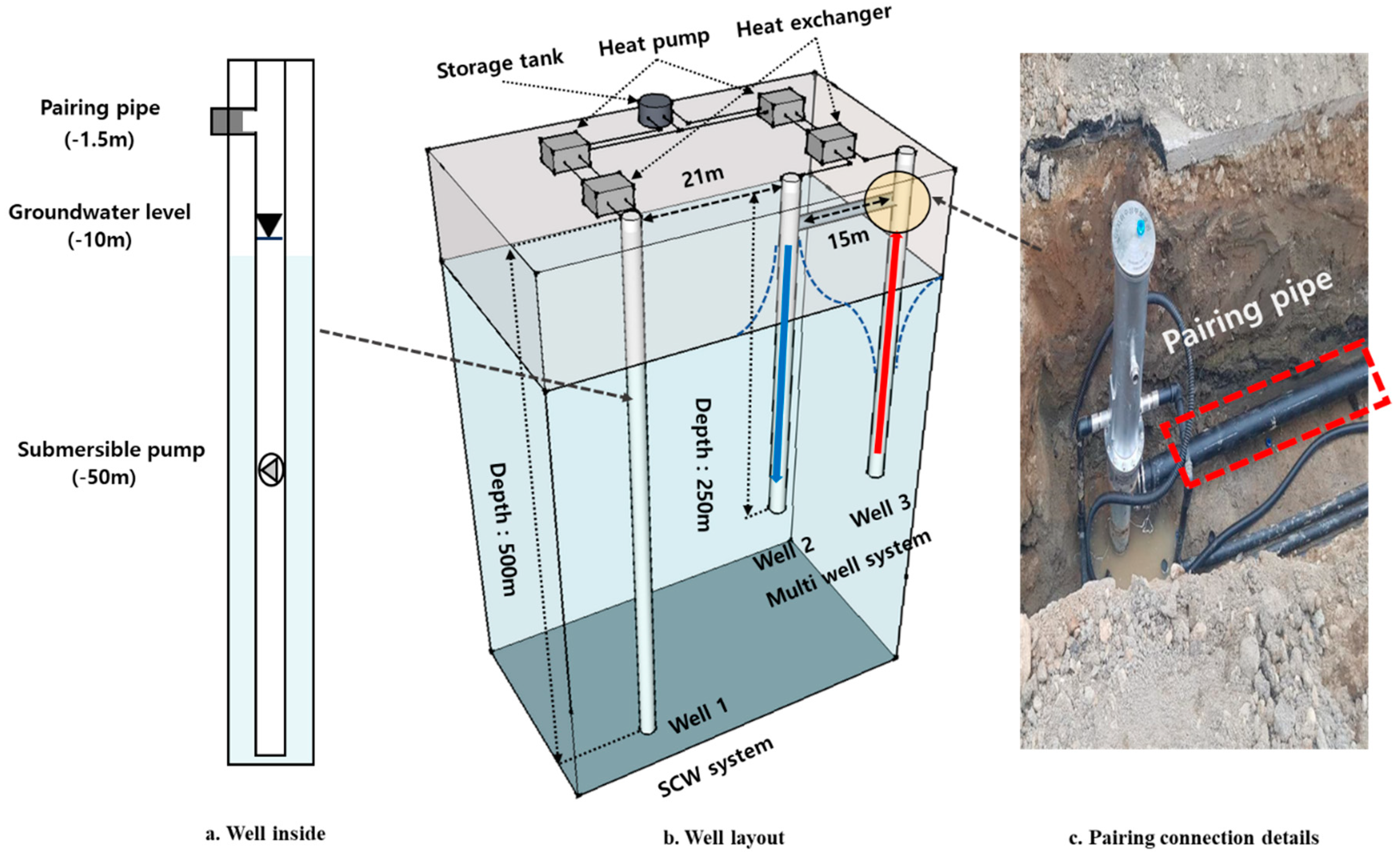
2. Summary of the Developed System

The pairing technology aims to obtain water level equilibrium between two wells (supply well and injection well) by installing a spillway, in which fluid can flow, between two wells of a multi-well system. Figure 1 shows the groundwater distribution between the supply well and injection well of a multi-well system through the system operation. The groundwater is sent from the supply well to the heat exchanger through the deep well pump, and because of this, the groundwater level of supply well drops. On the other hand, the groundwater level in the injection well rises due to the injection of water coming from the heat exchanger after heat exchange. Figure 2 shows the supply well and injection well of multi-well system that applied the pairing system developed in this study. Here, the pairing pipe connects the supply well and the injection well and facilitates the free movement of fluid between the two wells. In other words, if a pairing pipe is in place, the water will flow into the supply well through the pairing pipe when the groundwater level is higher than the pairing depth.
When the groundwater level of the injection well is lower than the pairing depth, the groundwater level will be recovered through the ground only, but when the groundwater level of the injection is higher than the pairing depth, the groundwater level recovery through the ground and the groundwater level recovery through the pairing occur simultaneously. Therefore, the pairing technology can solve the problems regarding the overflow phenomenon and the pump power consumption increase occurring in multi-well systems.

3. Real-Scale Experiment

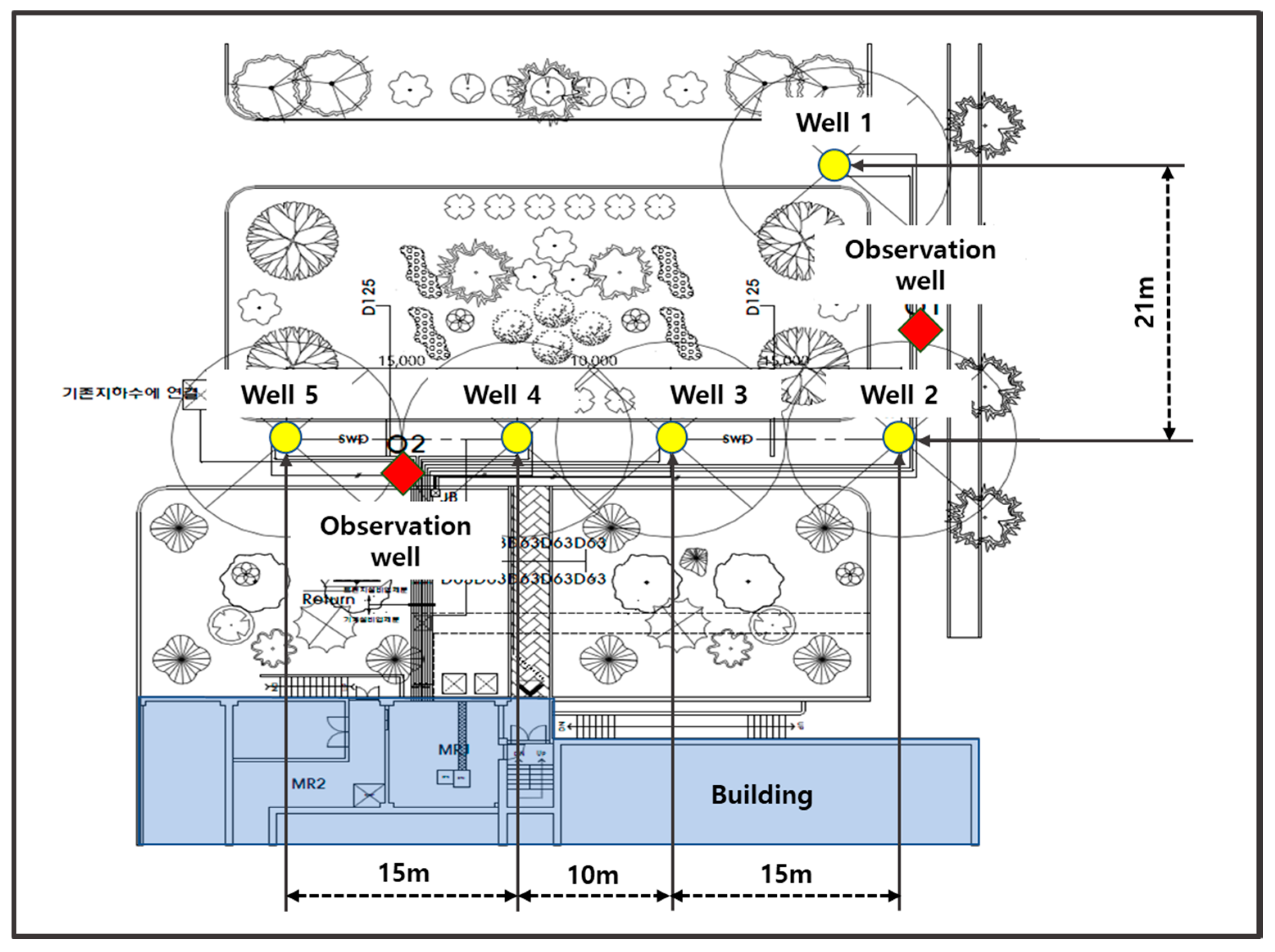
3.1. The Experimental Site and the Analysis of Hydro-Geological Characteristics of Site

The study object of the experiments was the load of a library building located in Nowon-gu (Seoul, South Korea). Five wells were drilled in front of the library (Figure 3). Here, a 500 m well was drilled for Well 1 to use it as a well of a standing column well (SCW) system. For Wells 2–5, 250 m wells were drilled for the multi-well open-loop system that adopted the pairing technology. Prior to performing the experiment, the hydro-geological characteristics of each geothermal well were investigated. Table 1 shows the specifications of the experimental wells for the aquifer experiment. For each experimental well, a step drawdown test and a long-term pumping test were performed. The step drawdown test was carried out by installing a 3.72 kW submersible pump at 100 m depth in each geothermal well. The pumping rate was changed in 4–5 steps for each well. Table 2 shows the step drawdown test results for each experimental well. In the step drawdown tests, the optimal pumping rate of Well 2 was calculated as 60 m3/day by the double inflection point method. For the other wells, the measured optimal pumping rates exceeded the expected pumping rates.
In the long-term pumping tests, a 3.73 kW submersible pump was installed at the same position as the step drawdown tests and the water was pumped for 20 h at the optimal pumping rate. After reaching a stable water level, a water level recovery test was performed. Table 3 shows the hydraulic conductivity calculated through the long-term pumping tests and the water level recovery tests. Here, the hydraulic conductivity shows the average of values calculated through Theis [14], Cooper and Jacob [15], and recovery tests. The hydraulic conductivity of Well 1 was confirmed to be 2.88 × 10⁻⁶ m/s. The hydraulic conductivity of Well 2 was 5.82 × 10⁻⁸. The hydraulic conductivities of Wells 3–5 were in the range of 5.28 × 10⁻⁶ m/s–6.89 × 10−6 m/s, which was about 100 times higher than the hydraulic conductivity of Well 2. In this study, using the pairing in the unfavorable condition of hydraulic conductivity like that of Well 2, the adoptability of multi-well pairing system was investigated. Therefore, Well 2 was used as a injection well of multi-well pairing system and Well 3 as a supply well. Meanwhile, Well 1 was used as a well of SCW system.

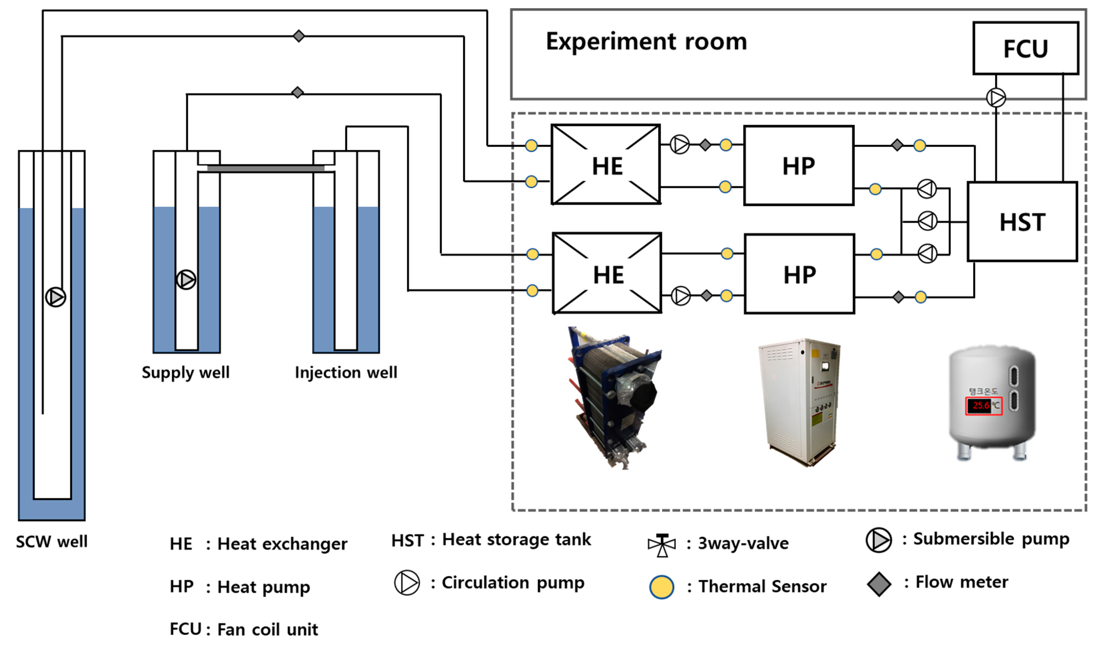
3.2. Experiment Overview

Figure 4 shows the wells of the SCW system and the multi-well pairing system. The pipe diameter in each geothermal well was 250 mm. The depth of the geothermal well of the SCW geothermal well system was 500 m. The distance between the supply well and the injection well of the multi-well pairing system was 15 m and the depth of the supply well and injection well was 250 m, respectively. The pairing pipe was installed between the supply well and the injection well at 1.5 m depth. Figure 5 shows the system overview. The SCW system and the multi-well pairing system were used for the heating and cooling loads of same space and they shared the heat storage tank. The specifications of plate heat exchanger and heat pump used in the SCW system and the multi-well pairing system were identical. The specifications of plate heat exchanger, heat pump, heat storage tank, submersible pump, and circulation pump used in the experiment are shown in Table 4. The heat pump was repeatedly operated and stopped according to the set temperature of the heat storage tank, 45 °C ± 3 °C. The flow rate of the submersible pump was 432 m3/d maximum and that of circulation water was 346–360 m3/d (Table 5).

3.3. Calculation Method of System Performance

To quantitatively analyze the heating and cooling performance of the SCW system and multi-well pairing system, the temperature, flow rate, and power consumption were measured at the heat source side and load side during the system operating hours. Equation (1) was used for the heat exchanged from the heat storage tank though the heat pump. For the heating and cooling performance coefficient, Equation (2) was used. For the heating and cooling performance coefficient of total system, Equation (3) was used.
Heat exchange rate:
Q l o a d = F l o a d × c × Δ T
Heat pump coefficient of performance:
H . EER   and   H . COP = Q l o a d W h p
System coefficient of performance:
S . EER   and   S . COP = Q l o a d W h p + W s + W c
where Q l o a d is the heat exchange rate of heat pump (kW), F l o a d is the flow rate on the load side (kg/s), c is the specific heat of water (kJ/kg·°C), Δ T is the difference of temperature on the load side(°C), W h p is the power consumption of heat pump (kW), W s is the power consumption of submersible pump (kW) W c is the power consumption of circulation pump (kW), H . COP is the coefficient of performance of heat pump for heating (kW/kW), S . COP is the coefficient of performance of system for heating (kW/kW), H.EER is the energy efficiency ratio of heat pump for cooling (kW/kW), S.EER is the energy efficiency ratio of system for cooling (kW/kW).

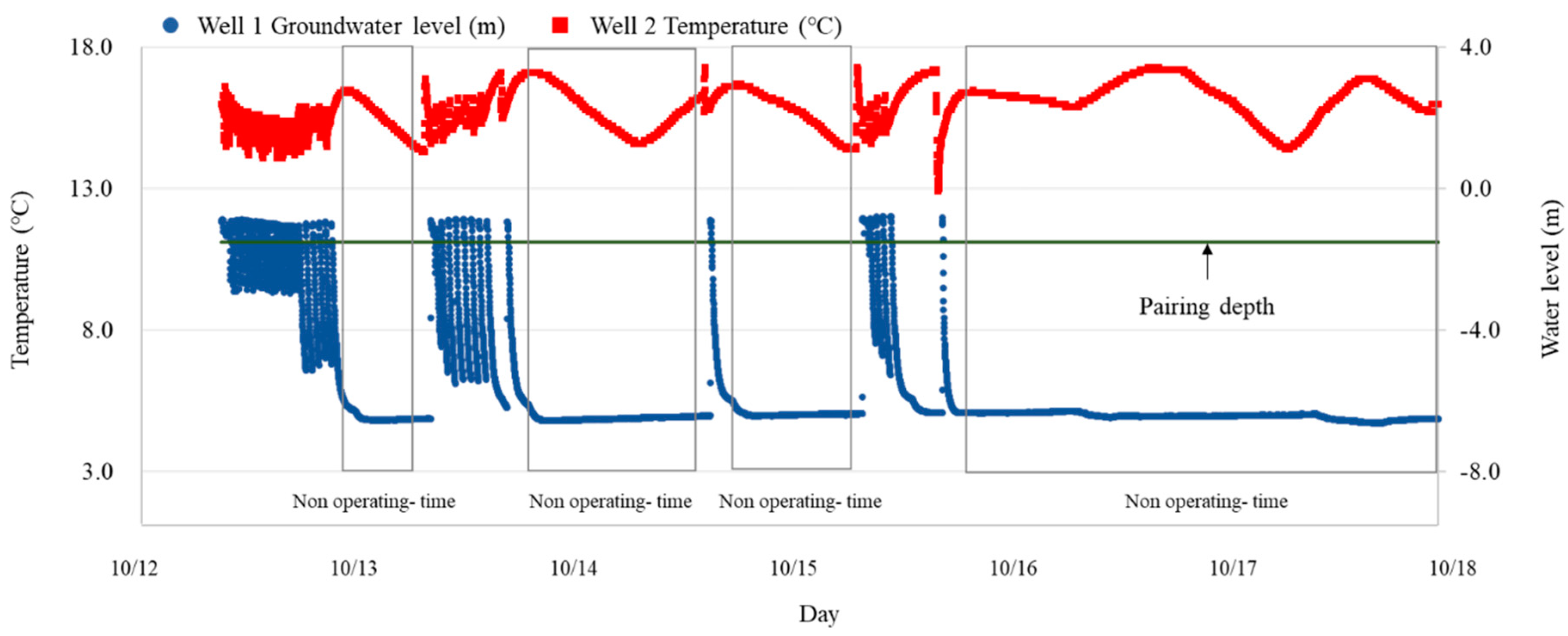
3.4. Experimental Results

Figure 6 is a graph showing the groundwater level of the injection well and the temperature of the supply well during heating operation from 12–18 October 2017. Whenever the system was operated, it was confirmed that the groundwater level distribution was higher than the position of pairing pipe. However, the maximum groundwater level was −0.8 m and consequently, the overflow phenomenon did not occur in the injection well. It was determined that the overflow was prevented since the groundwater moved through the pairing pipe. For the heat source temperature in the supply well, the groundwater inside the pipe connected to the plate heat exchanger was measured. As a result, when the system is not operated, the heat source temperature showed a decreasing tendency since it was affected by the air temperature. Hence, the heat source temperatures were compared for the system operating hours. The heat source temperature of Well 2 (Figure 6) was 12.9 °C minimum and 17.3 °C maximum, showing the difference of 4.4 °C during the operating hours since flow of groundwater occurred through the pairing.
On the other hand, when a flow through the pairing did not occur, the temperature change of supply well was only about 2.1 °C. As a result of investigating the hydro-geological characteristics of Well 2, the hydraulic conductivity was 5.82 × 10⁻⁸, which was considerably lower than that of surrounding ground. However, because of the pairing technology implementation, the problem of limited operation caused by the overflow phenomenon did not occur. Moreover, although there were temperature changes of supply well due to the flow through the pairing, the heat source temperature was 12.9 °C minimum, which satisfied the operating conditions.
Figure 7 is a graph comparing the heating and cooling performances of the SCW system and multi-well pairing system. The cooling performances were measured for 18 days from 10–27 September 2017. The heating performances were measured for 18 days from 12–29 November 2017. The SCW system and the multi-well pairing system were operated simultaneously to deal with the building load. When cooling, S.EER of multi-well pairing system was 29% higher than that of SCW system. On the other hand, when heating, S.COP of multi-well pairing system was 10% lower than that of SCW system. The total power consumption for heating and cooling was 4% lower in the multi-well pairing system than the SCW system. Meanwhile, no overflow phenomenon occurred in the injection well of multi-well pairing geothermal system during the heating and cooling experimental periods.

4. Multi-Well Pairing Heat Exchange Model

4.1. Numerical Multi-Well Pairing Model

In order to develop a performance prediction model of the multi-well pairing geothermal system, it is necessary to analyze the groundwater flow and the geothermal movement simultaneously. Therefore, in this study, FEFLOW [16] was used to analyze heat movement and groundwater flow of around wells in saturated and unsaturated state. This simulation tool is widely used for analysis of ground pollution, underground thermal behavior and groundwater movement. Furthermore, it can enhance the prediction accuracy based on finite element method and individual calculation in three phases (solid, liquid and gas). Nam and Ooka [17] developed a performance prediction method of open-loop geothermal system by using FEFLOW, and the accuracy was verified by comparing with the measurement result and the analysis result.
For the developed model, the hydro-geological conditions and the well design conditions were set up by simulating a real-scale ground experiment. With respect to the ground conditions, the modelling was performed based on the hydro-geological characteristics and thermal conductivity investigation, and the specifications of geothermal wells and the pairing were set up similar to those of actual design. Figure 8 shows a tetra mesh whereby the ground and geothermal wells were constructed in the numerical analysis model. The gap between two wells was set as 15 m and the diameter of well was 250 mm. Furthermore, the model was constructed with the analysis zone having 30 m spaces in four directions from the wells. Table 6 shows the analysis conditions input into the numerical analysis model.

4.2. Analysis Method of Spill-Way

In this simulation, the spill-way was assumed as a channel-type mesh (0.25 m × 0.1 m) with the length of 15 m. It was set at the depth of 1.5 m, the same as in the real-scale experiment. Here, when groundwater level reaches the depth of spill-way (1.5 m), the groundwater moves from the injection well side to supply well side with the velocity calculated by the following equations.
In general, the flow of groundwater through the ground can be analyzed by Darcy’s law (Equation (4)) derived from equation of fluid movement penetrating the porous medium:
v = F A = k × Δ h l
where v is the flow velocity of groundwater (m/s), F is the flow rate (m3/s), A is the cross-sectional area (m2) of ground, k is the hydraulic conductivity (m/s), Δ h is the water head difference (m) of supply well and injection well, and l is the length (m) of supply well and injection well.
However, it is difficult to represent the spill-way in the FEFLOW simulation, so in this study, the region of spill-way was set to very high hydraulic conductivity (24.5 m/s). The value was calculated by Bernoulli’s equation and Darcy-Weisbach equation [18]. Δ h can be expressed as:
Δ h = h i + h l + h o
where h i is the loss of head at entrance (m), h l is the loss of head due to friction (m), and h o is the loss of head at outlet (m). Equation (5) can be expressed as follows by Bernoulli’s law and Darcy-Weisbach equation:
Δ h = f e v 2 2 g + f l v 2 l 2 g D + f i v 2 2 g
where D is the hydraulic diameter (m), g is the gravitational acceleration (m/s2). Equation (6) can be summarized as:
v = 2 g Δ h f i + f l l d + f o
where f i is the entrance-loss coefficient (non-dimension), f l is the coefficient of friction (non-dimension), and f o is the run-off coefficient (non-dimension). k can be derived by combining Equations (4) and (7) as:
k = 2 g l 2 Δ h ( f i + f l l d + f o )

4.3. Comparison of Simulation Results and Experimental Measures

To verify the accuracy of the performance estimation model of the multi-well pairing geothermal system, the experimental and analysis results were compared. Figure 9 shows the temperature fluctuation of the supply and injection well during 136 h as the comparison of the experimental measures and the simulation results. The experimental measures and simulation results of injection well showed that the fluctuation of temperature according to the system operation were similar. However, there were some differences between the experimental measures and the simulation results for the supply well temperatures because it was difficult to consider underground environment factors such as the temperature field of the soil and cracks in the rocks. To quantitatively analyze the accuracy of the numerical analysis model, the errors were calculated by using the mean bias error (MBE) Equation (9) and the coefficient of variation of root mean square error (Cv(RMSE)) (Equation (10)).
Mean bias error:
MBE ( % ) = ( N E ) h E h
Coefficient of variation of root mean square error:
Cv ( RMSE ) ( % ) = ( N E ) 2 h T h × T h E h × 100
where N h is the hourly mean temperature of the numerical analysis values, E h is the hourly mean temperature of experimental values, T h is the total hours measured.
As a result of calculating the errors, the maximum MBE value of the supply well temperature was −1.6% and the maximum MBE value of the injection well temperature was 3.7%. Cv(RMSE) was 1.1% for the supply well temperature and 1.9% for the injection well temperature. The validity of the simulation method was verified through the comparison between the experiment results and simulation results.

5. Case Study by Simulation

5.1. Case Condition

In this section, in order to decide the conditions in which the spill-way was required, case studies under various ground and operation conditions were conducted by simulation. In addition, the effect of the spill-way on the groundwater level was analyzed by installing pairing under conditions where overflowing occurred. The numerical analysis was performed by assuming continuous operation. The groundwater level was measured around the injection well on the ground surface. Table 7 shows the hydraulic conductivity and pumping rate conditions. The range of hydraulic conductivity is from 8 × 10⁻⁷ m/s to 2 × 10⁻⁷ m/s. The pumping rate conditions were set at 300, 400 and 500 m3/d. When overflow occurred, additional numerical analysis was performed by entering the pairing conditions.

5.2. Results

In this study, the performance of the pairing system installation was evaluated by determining the effects of pumping rate and hydraulic conductivity on the groundwater level at the injection well. Table 8 shows the result of simulation for groundwater level of supply and injection well according to case conditions. Figure 10 shows the groundwater levels at three different pumping rates when the hydraulic conductivity equaled 4 × 10⁻⁷ m/s. The groundwater level at the injection well was elevated over time by increasing the pumping rate. Figure 11 shows the groundwater levels at the injection well at three different pumping rates with an initial hydraulic conductivity of 4 × 10⁻⁷ m/s. At this hydraulic conductivity, the maximum difference between injection well groundwater levels at different pumping rates was determined to be 3.77 m. The groundwater level at the injection well decreased by 8.21 m as hydraulic conductivity increased from the initial value to 8 × 10⁻⁷ m/s at a pumping rate of 500 m3/d. Hence, hydraulic conductivity had a greater effect on the groundwater level at the injection well than did the pumping rate.
Figure 12 shows groundwater levels in the presence or absence of the multi-well pairing system at a hydraulic conductivity of 2 × 10⁻⁷ m/s and a pumping rate of 500 m3/d. Without the pairing system, the maximum groundwater level at the injection well was 18.71 m, and overflow occurred. On the other hand, when the pairing system was installed, the maximum injection well groundwater level was −3.16 m, and overflow was not observed. Thus, at a pumping rate of 500 m3/d and a hydraulic conductivity of 2 × 10⁻⁷ m/s, the difference between groundwater levels with and without the pairing system was 21.87 m. Figure 13 shows the maximum groundwater levels at the injection well with and without the pairing system as pumping rate was increased at a hydraulic conductivity of 2 ×10⁻⁷ m/s. With no pairing system installed, overflow occurred at each pumping rate. In addition, the groundwater level increased linearly with increasing pumping rate. However, the groundwater level reached a maximum of −3.14 m when the pairing system was installed.

6. Conclusions

In this study, a multi-well pairing system was developed that prevented overflow and clogging of the injection well to achieve sustainable system operation. The performance of the multi-well pairing system and that of a standing column well (SCW) system were comparatively analyzed in a field-scale experiment. In addition, numerical simulations were performed to evaluate the performance of the multi-well system with and without pairing by analyzing the effects of varying hydraulic conductivities and pumping rates on groundwater level. The result of the study are as follows:
(1)
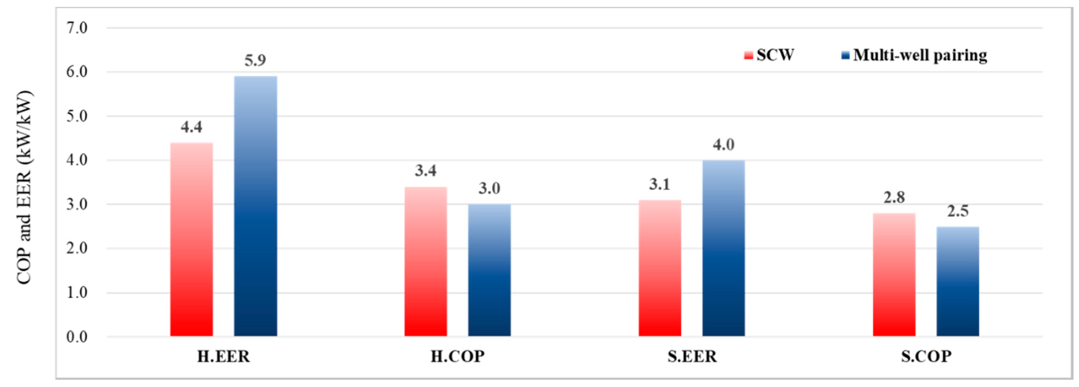
The cooling and heating performance of the multi-well pairing system was compared to that of a SCW system under identical load conditions in a field-scale experiment. The cooling performance of the multi-well pairing system was 29% better than that of the SCW system, while its heating performance was 10% lower than that of the SCW system. Total power consumption in the multi-well pairing system for heating and cooling was 4% lower than in the SCW system. When annual operating costs are considered, the multi-well pairing system can be more economical than a SCW system. However, the field experiment only lasted for 18 days, therefore, data from long-term operation of the multi-well pairing system should be analyzed to assess the reliability of these results.
(2)
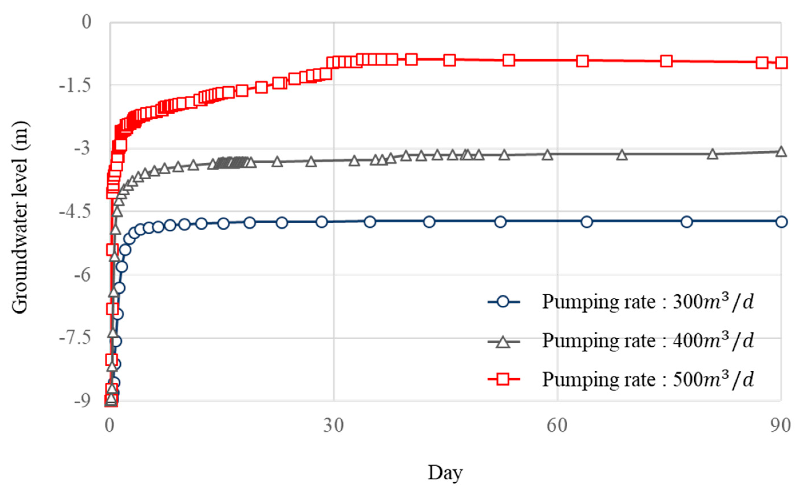
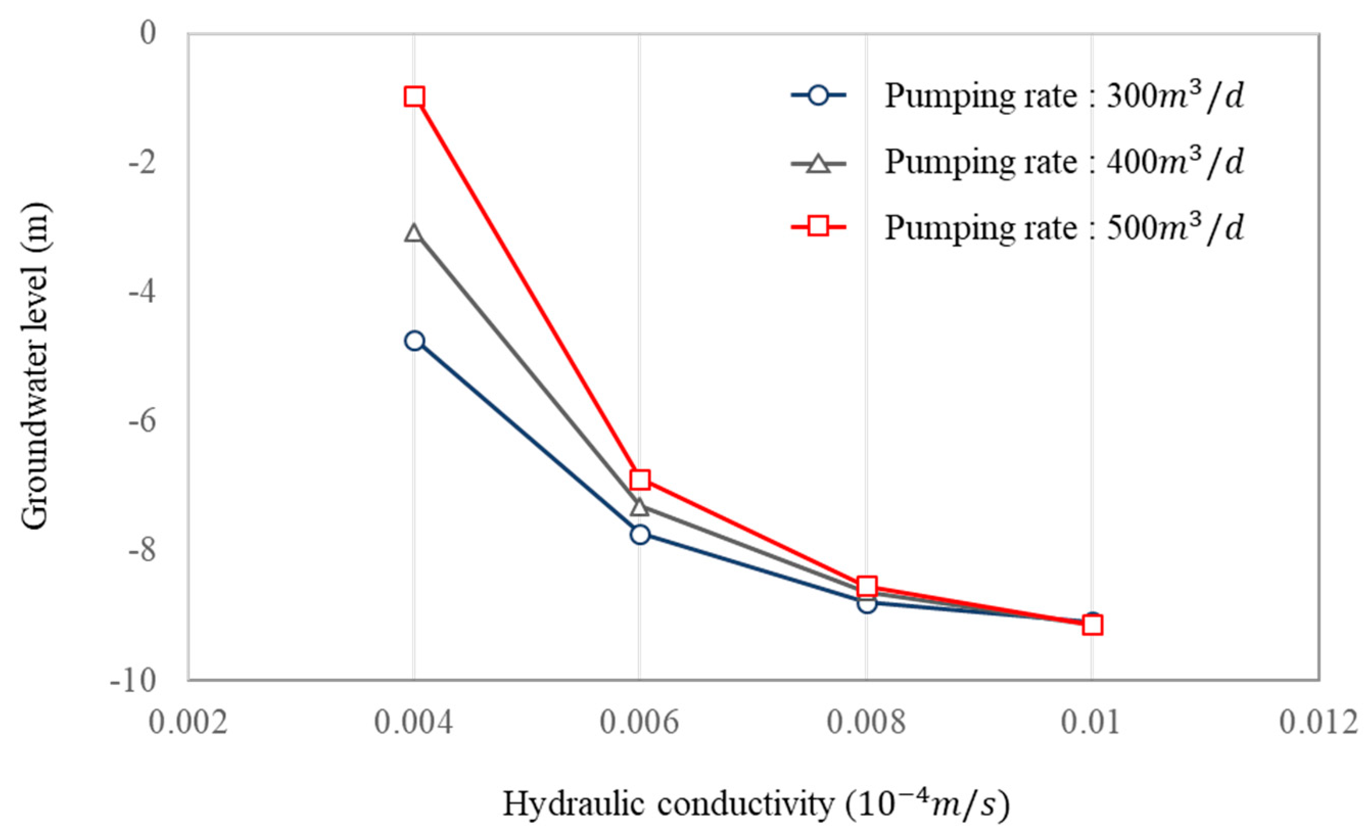
The numerical simulation was conducted to analyze the effect of hydraulic conductivity and pumping rate conditions on groundwater level at the injection well. The results of the numerical simulation showed that the impact of hydraulic conductivity on groundwater level was greater than that of pumping rate. Overflow of the injection well did not occur when the hydraulic conductivity equaled or exceeded 4 × 10⁻⁷ m/s. We consider sustainable operation of the multi-well system to be possible under these conditions.
(3)
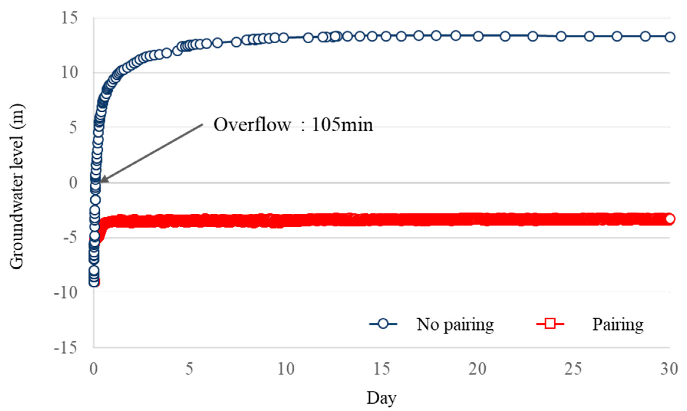
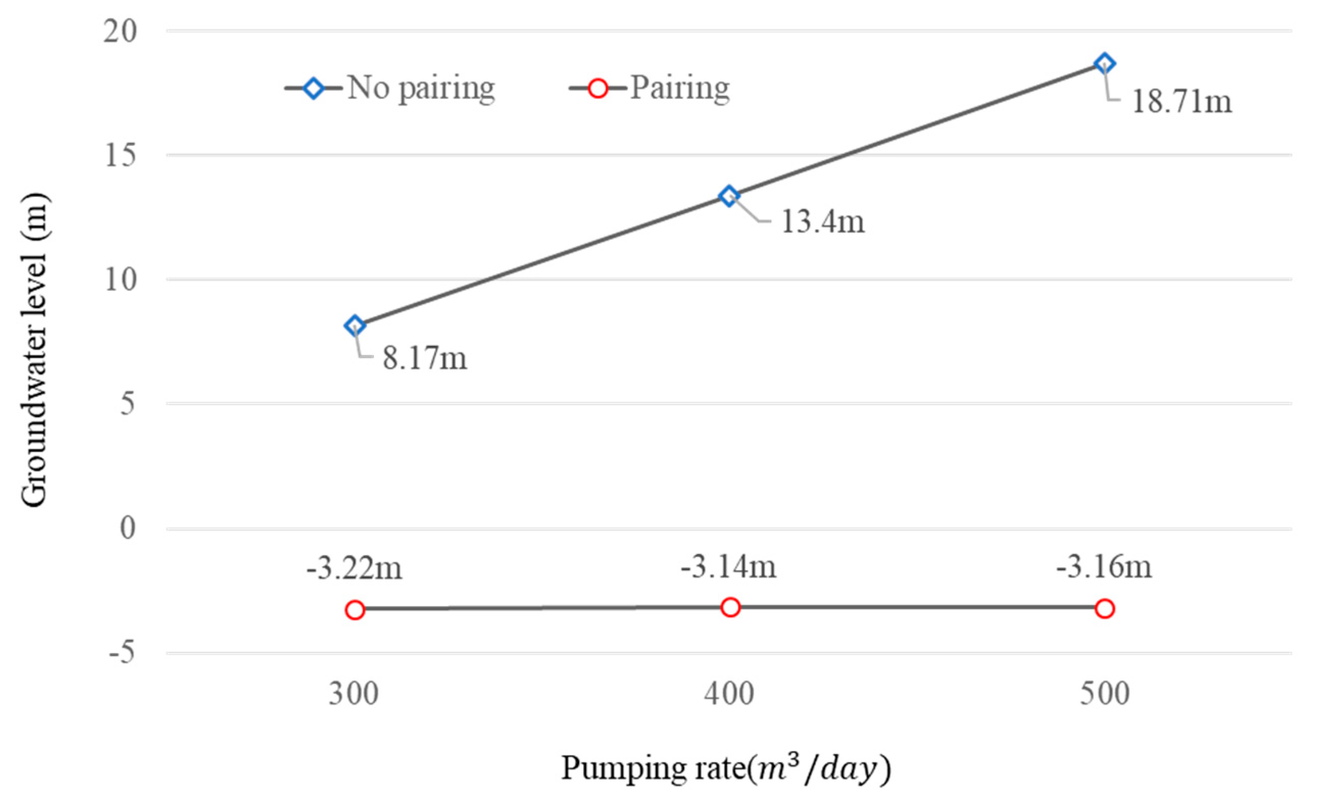
At a hydraulic conductivity of 2 × 10⁻⁷ m/s without pairing, the groundwater level rose to 18.71 m at the injection well, resulting in overflow. In contrast, the multi-well pairing system raised the groundwater level to just −3.14 m. Based on the simulation results, pairing installation made sustainable operation possible even under conditions of low hydraulic conductivity. The groundwater level at the supply well was increased by pairing installation. Pairing installation is therefore expected to reduce power consumption by the supply well pump. However, the heat source temperature changes when groundwater moves from the injection well to the supply well via the spill-way. Therefore, heat source temperature and groundwater level should be considered simultaneously for the establishment of a pairing system design method.
A parameter study of spill-way design factors will be conducted in the future to develop an optimum design method. Groundwater, well, and building load conditions will be considered when the optimized algorithm is used to establish the design guide for multi-well pairing system development.

Author Contributions

Methodology, H.K. and Y.N.; Investigation, O.J.; Data Curation, S.m.B.; Writing-Original Draft Preparation, H.K.; Writing-Review & Editing, H.K. and Y.N.; Supervision, Y.N.

Acknowledgments

This research was supported by a grant (18CTAP-C116546-03) from Technology Advancement Research Program (TARP) funded by Ministry of Land, Infrastructure and Transport of Korean government.

Conflicts of Interest

The authors declare no conflicts of interest.

References

  1. Hahn, J.-S.; Han, H.-S.; Hahn, C. Geothermal Energy; Hanrimwon: Seoul, Korea, 2010; pp. 1–43. ISBN 978-899-351-221-2. [Google Scholar]
  2. Rafferty, K.D. Design issues in commercial open-loop heat pump systems. ASHRAE Trans. 2000, 114, 6–10. [Google Scholar]
  3. Kwon, K.-S.; Lee, J.-Y.; Mok, J.-K. Update of current on ground source heat pumps in Korea (2008–2011). J. Geol. Soc. Korea 2012, 48, 193–199. [Google Scholar]
  4. Zhou, X.; Gao, Q.; Chen, X.; Yu, M.; Zhao, X. Numerically simulating the thermal behaviors in groundwater wells of groundwater heat pump. Energy 2013, 61, 240–247. [Google Scholar] [CrossRef]
  5. Lo Russo, S.; Taddia, G.; Verda, V. Development of the thermally affected zone(TAZ) around a groundwater heat pump(GWHP) system: A sensitivity analysis. Geothermics 2012, 43, 66–74. [Google Scholar] [CrossRef]
  6. Lo Russo, S.; Gnavi, L.; Roccia, E.; Taddia, G.; Verda, V. Groundwater Heat Pump (GWHP) system modeling and Thermal Affected Zone (TAZ) prediction reliability: Influence of temporal variations in flow discharge and injection temperature. Geothermics 2014, 51, 103–112. [Google Scholar] [CrossRef]
  7. Kim, J.; Nam, Y. A Numerical Study on System Performance of Groundwater Heat Pumps. Energies 2016, 9, 4. [Google Scholar] [CrossRef]
  8. Al-Habaibeh, A.; Atheresh, A.P.; Parker, K. Performance analysis of using mine water from an abandoned coal mine for heating of buildings using an opern loop based single shaft GSHP system. Appl. Energy 2018, 211, 393–402. [Google Scholar] [CrossRef]
  9. Zhen, J.; Lu, J.; Huang, G.; Zhang, H. Groundwater source heat pump application in the heating system of Tibet Plateau airport. Energy Build. 2017, 136, 33–42. [Google Scholar] [CrossRef]
  10. Park, B.-H.; Lee, B.-H.; Lee, K.-K. Experimental investigation of the thermal dispersion coefficient under forced groundwater flow for designing an optimal groundwater heat pump (GWHP) system. J. Hydrol. 2018, 562, 385–396. [Google Scholar] [CrossRef]
  11. Park, B.-H.; Bae, G.-O.; Lee, K.-K. Importance of thermal dispersivity in designing groundwater heat pump (GWHP) system: Field and numerical study. Renew. Energy 2015, 83, 270–279. [Google Scholar] [CrossRef]
  12. Park, Y.; Kim, N.; Lee, J.Y. Geochemical properties of groundwater affected by open loop geothermal heat pump systems in Korea. Assoc. Korea Geosci. Soc. Springer 2015, 19, 515–526. [Google Scholar] [CrossRef]
  13. Bae, S.; Kim, H.; Kim, H.-W.; Nam, Y. Study on the Underground Thermal Environment around Wells for a Design Method of Open-Loop Geothermal System. Trans. Korea Soc. Geotherm. Energy Eng. 2017, 13, 14–20. [Google Scholar] [CrossRef] [Green Version]
  14. Theis, C.V. The relation between the lowering of the piezometric surface and the rate and duration of discharge of a well using ground-water storage. Am. Soc. Civ. Eng. 1935, 2, 519–524. [Google Scholar] [CrossRef]
  15. Cooper, H.H.; Jacob, C.E. A generalized graphical method of evaluating formation constants and summarizing well-field history. Am. Geophys. Union Trans. 1946, 27, 526–534. [Google Scholar] [CrossRef]
  16. Diersch, H.-J.G. FEFLOW Reference Manual; WASY GmbH: Berlin, Germany, 2009. [Google Scholar]
  17. Nam, Y.; Ooka, R. Numerical simulation of ground heat and water transfer for groundwater heat pump system based on real-scale experiment. Energy Build. 2010, 42, 69–75. [Google Scholar] [CrossRef]
  18. Sarkar, B.K. Fluid Mechanics and Hydraulic Machines through Practice and Solved Problems; Sunil Sachdev: New Delhi, India, 1999; Chapter 6; pp. 110–121. ISBN 81-7023-977-110-064. [Google Scholar]
Figure 1. Groundwater level change during system operation (without pairing).
Energies 11 03485 g001
Figure 2. Groundwater level change during system operation (with pairing).
Energies 11 03485 g002
Figure 3. Experimental site plan.
Energies 11 03485 g003
Figure 4. Overview of the experimental site.
Energies 11 03485 g004
Figure 5. Schematic diagram.
Energies 11 03485 g005
Figure 6. Supply well temperature and injection well groundwater level.
Energies 11 03485 g006
Figure 7. The cooling and heating performance of the standing column well (SCW) system and multi-well pairing system.
Energies 11 03485 g007
Figure 8. Simulation model.
Energies 11 03485 g008
Figure 9. Comparison of the simulation and experiment results.
Energies 11 03485 g009
Figure 10. Groundwater level at the injection well in the condition of different pumping rates (hydraulic conductivity: 4 × 10⁻⁷ m/s).
Energies 11 03485 g010
Figure 11. Groundwater level at the injection well in the condition of different hydraulic conductivities and pumping rates.
Energies 11 03485 g011
Figure 12. Groundwater level at the injection well in the presence or absence of the pairing system (hydraulic conductivity: 2 × 10⁻⁷ m/s; pumping rate: 500 m3/d).
Energies 11 03485 g012
Figure 13. Groundwater level at the injection well by pumping rate in the presence or absence of the pairing system (hydraulic conductivity: 2 × 10⁻⁷ m/s).
Energies 11 03485 g013
Table 1. Well specifications.
Well No.Well Depth (m)Well Diameter (mm)Measure Point (m)
Well 15002500.06
Well 22502500.25
Well 32502500.43
Well 42502500.23
Well 52502500.24
Table 2. Step drawdown test results.
WellPumping Rate (Q, m3/d)Drawdown Water Level (Sw, m)Optimal Pumping Rate (Q, m3/d)
1st2nd3rd4th5th1st2nd3rd4th5th
Well 1150200250300--7.057.487.92-300 < Q o p t i m u m
Well 240506070-13.218.0924.6241.47-60 = Q o p t i m u m
Well 3708090100-10.5912.715.2618.09-100 < Q o p t i m u m
Well 41502002503003501.151.862.482.994.07350 < Q o p t i m u m
Well 5100200300400-0.651.11.912.64-400 < Q o p t i m u m
Table 3. Long- term pumping test result.
Well No.Pumping Rate (Q, m3/d)Hydraulic Conductivity (m/s)
Well 13002.88 × 10−6
Well 2505.82 × 10−8
Well 3905.69 × 10−6
Well 43006.89 × 10−6
Well 54005.28 × 10−6
Table 4. System equipment specification.
System PartsSpecifications
SCWMulti-Well
WellNumber of well12
Well diameter250 mm250 mm
Depth500 m250 m
Spill-waySpill-way diameter-125 mm
Spill-way length-15 m
Heat exchangerHeat exchanger capacity104.6 kW
Heat pumpHeating capacity88.2 kW
Cooling capacity84.5 kW
Heat Storage tankCapacity3.09 m3
Circulation pumpPower1.5 kW
Submersible pumpPower3.7 kW
Table 5. Experiment condition.
ElementCondition
Building typeLibrary
Temperature set45 °C
Dead bend set3 °C
Maximum heat exchanger flow set432 m3/d
Maximum heat pump flow set346 m3/d
Maximum load flow set360 m3/d
Table 6. Ground conditions of numerical analysis model.
ElementSupply WellInjection Well
Groundwater Level (m)9.019.09
Hydraulic conductivity (m/s)6.89 × 10−65.28 × 10−6
Ground temperature (°C)1515
Thermal conductivity (W/m·K)2.9442.944
Table 7. Simulation condition of all cases.
CaseHydraulic Conductivity (10−4 m/s)Pumping Rate (m3/Day)Pairing (Installed/Not Installed)
Case N10.008300Not installed
Case N20.008400Not installed
Case N30.008500Not installed
Case N40.006300Not installed
Case N50.006400Not installed
Case N60.006500Not installed
Case N70.004300Not installed
Case N80.004400Not installed
Case N90.004500Not installed
Case N100.002300Not installed
Case N110.002400Not installed
Case N120.002500Not installed
Case P100.002300Installed
Case P110.002400Installed
Case P120.002500Installed
Table 8. Analysis results of all cases.
CaseMin. GWL of Supply Well (m)Max. GWL of Injection Well (m)Difference in GWL between Supply and Injection Well (m)Overflow (Occurred/Not Occurred)
Case N1−9.26−8.710.55Not occurred
Case N2−9.35−8.620.73Not occurred
Case N3−9.43−8.520.91Not occurred
Case N4−10.21−7.692.52Not occurred
Case N5−10.62−7.273.35Not occurred
Case N6−11.04−6.854.19Not occurred
Case N7−13.17−4.738.44Not occurred
Case N8−14.57−3.0711.50Not occurred
Case N9−16.20−0.8615.34Not occurred
Case N10−15.248.1723.41Occurred
Case N11−15.4113.3228.73Occurred
Case N12−15.5018.7134.21Occurred
Case P10−9.00−3.225.78Not occurred
Case P11−9.00−3.145.86Not occurred
Case P12−9.06−3.165.90Not occurred
GWL: Groundwater level.

