Abstract
Remote communities that have limited or no access to the power grid commonly employ diesel generators for communal electricity provision. Nearly 65% of the overall thermal energy input of diesel generators is wasted through exhaust and other mechanical components such as water-jackets, intercoolers, aftercoolers, and friction. If recovered, this waste heat could help address the energy demands of such communities. A viable solution would be to recover this heat and use it for direct heating applications, as conversion to mechanical power comes with significant efficiency losses. Despite a few examples of waste heat recovery from water-jackets during winter, this valuable thermal energy is often discarded into the atmosphere during the summer season. However, seasonal thermal energy storage techniques can mitigate this issue with reliable performance. Storing the recovered heat from diesel generators during low heat demand periods and reusing it when the demand peaks can be a promising alternative. At this point, seasonal thermal storage in shallow geothermal reserves can be an economically feasible method. This paper proposes the novel concept of coupling the heat recovery unit of diesel generators to a borehole seasonal thermal storage system to store discarded heat during summer and provide upgraded heat when required during the winter season on a cold, remote Canadian community. The performance of the proposed ground-coupled thermal storage system is investigated by developing a Computational Fluid Dynamics and Heat Transfer model.
1. Introduction
Communities situated on distant land masses that have either limited or no proper access to the communal facilities, such as power lines and road access, are generally deemed as “remote communities”. These remote communities are usually dependent on local fossil-based power generation. Diesel generators are the most common choice for on-site electricity generation in these communities. In countries like Canada and Norway, logistic and transportation challenges result in sizeable increases in fuel costs for remote communities compared to their urban counterparts. This impact results in relatively higher living and industrial costs. Nunavut, where many remote communities are situated, is a good example to better illustrate this cost difference for Canada. A study suggested the cost of obtaining the same amount of energy for Nunavut communities is almost ten times higher than the Canadian average [1].
Analyses conducted on a wide range of modern generators have shown that nearly 65% of the overall energy generated in a diesel engine is discarded as heat through water-jackets, aftercoolers, and exhaust [2]. This means, approximately 2 kWh worth of heat is simply discarded through several streams in the generation of 1 kWh of electricity. Recovering heat from cylinder block or jacket water is a common practice for space heating purposes. However, despite being suggested by many studies [2,3,4,5], heat recovery from exhaust streams of diesel gen-sets is still not commonly observed in practical applications.
Many studies have elaborated on conversion of waste heat from diesel gen-sets to mechanical power by use of Organic Rankine Cycle (ORC) [6,7,8,9]. Some of them have focused on the heat recovery process [10,11] or performance of different heat exchangers involved in capturing this heat [12,13,14]. There are also other studies signifying the potential of thermoelectric systems [15,16,17]. However, these studies imply that the efficiency of converting diesel waste heat to mechanical power is deemed to be relatively low mainly due to its low-temperature characteristics.
Aside from their need for power, remote communities are strongly reliant on fossil fuels for their heat demand as well. One way to relieve this fossil fuel dependency is to use the waste heat discarded from the diesel gen-sets. Nonetheless, unlike electricity, heat demand is typically dependent on seasonal temperature fluctuations and is not always highly needed. According to Erlund et al. [18], renewable heat sources are not always available in these remote locations and if available the capacity is inadequate to serve the peak and fluctuating demand. So, an alternative way to face this seasonal demand issue, while maximizing the waste heat recovery throughout the year, is to consider seasonal thermal energy storage (STES) methods. Seasonal thermal energy storage can compensate the year-round mismatch between the heat availability and the demand. By coupling an STES system to a waste heat recovery unit(s), the excess waste heat recovered from the diesel generators can be collected in a storage medium during the low-demand periods of summer for later use in winter, when the heat demand is higher. This alternative solution is not only greener, as it diminishes the fossil fuel consumption, but it is also reliable enough to help remote communities to save on their energy costs. In fact, Fisch et al. [19] studied and compared thirteen existing large-scale solar heating plants in six European countries with short-term (diurnal) and long-term (seasonal) storage applications. In their study, it was shown that the short-term storage could meet 10–20% of total annual heat demand while seasonal storage could provide 50–70% of this requirement with more visible impact on CO2 reduction [19].
A major challenge in STES is the storage medium and several solutions have been engineered for underground heat storage. Among such types of underground thermal storage techniques (e.g., hot-water thermal energy storage, borehole thermal energy storage, aquifer thermal energy storage, gravel-water thermal energy storage), borehole thermal energy storage (BTES) was selected for underground heat storage in this research. A BTES system is an underground structure that acts as a heat exchanger to transfer heat directly to and from the ground. This heat exchange is driven by the temperature difference between ground and working fluid allowing for both heat injection (warm fluid, cold ground) and extraction (cold fluid, warm ground) to be achieved. Heat injection can be conducted in the summertime (through U-tube pipes inserted into boreholes drilled at various depths). Inversely, heat extraction can be achieved during the winter time, when thermal energy is needed, by running the same system with an opposite temperature difference. This type of heat storage is available in most areas and does not have geographical limitations like aquifer and gravel-water thermal storage [20]. Moreover, less initial cost is required for BTES than hot water and gravel-water thermal storage, due to easier construction requirements [21]. Another advantage of BTES is benefiting from modular design, in which further boreholes can be attached to the system in response to changes in demand and/or supply [22]. In fact, BTES systems have been effectively employed in several STES applications [23,24,25,26,27]. It has been successfully applied mainly in thermal energy storage from solar heating collectors such as a full-scale system employed on a district heating network in Okotoks, Alberta, Canada [28]. The solar heating application has also been extensively studied both numerically [29,30] and experimentally [31,32]. Besides that, Welsch et al. [33] have shown over 40% reduction in greenhouse gas emission by attaching combined heat and power (CHP) plants and/or solar thermal collectors to BTES systems. McDaniel et al. [34] have shown the improvement in the flexibility of operating a CHP plant (combination of a gas turbine, a high-pressure steam turbine, and a low-pressure steam turbine) by coupling with a BTES system where it has replaced burning fossil fuel for heating purposes.
According to the abovementioned studies, coupling a BTES system with CHP power plants (solar, wind turbines, nuclear, steam turbine) is a sensible strategy. However, so far, no study has yet been found that shows the coupling between a BTES system with the waste heat recovery system from the diesel generators in the remote communities that intends to provide green heat according to the demand. The present study is unique in investigating the feasibility of using BTES systems for recovering waste heat of diesel generators used on remote locations in cold climate countries such as Canada and Norway. It offers a numerical simulation tool needed to assess the techno-economics of such systems and underlines the energy/environmental benefits of integrating BTES into remote power generation equipment. This study limits its scope by looking forward to providing green heat to the remote communities during winter only by using its existing power generation strategy. Any alternative idea to replace the power generation source is beyond the scope of this study.
2. Model Description
Figure 1 shows the schematics of the proposed system. In this scenario, during winter, borehole seasonal thermal storage (BTES) gives the initial heat load and the gen-set heat recovery unit upgrades the water temperature to meet the requirements of space heating for residential areas of nearby communities. This system will not only reduce the energy costs of these communities, but it would also be more environmentally friendly.
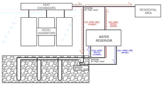
Figure 1.
Schematics of heat recovery, storage, and extraction by use of BTES (not to scale). Note that, BTES systems are individually represented as hot stream and cold stream for heat-injection and heat-extraction cases, respectively.
With an operational perspective, ideally, in BTES systems, water is used as the circulating fluid. Additionally, to have more effective heat transfer between the circulating fluid and the ground, the boreholes are usually filled with grout after U-tubes are installed. Also, to keep the heat losses at a minimum level, borehole fittings on the top surface need to be adequately insulated. Groundwater (seepage) flows can also lead to the loss of thermal energy. The studies of Xu et al. [30] and Pavlov and Olesen [31] can be used to better understand the impact of advection (i.e., groundwater movement) and whether it should be included or not. In this study, ground water movement is assumed to be insignificant, and therefore, its advective effects are neglected.
According to Lundh and Dalenback [26], in similar heat storage strategies, depending on the size and scale of the storage facility, at least 3–4 years of constant heat injection without any heat discharge may be required. This initially allows for a steady-state operational condition to be developed, for a more sustainable seasonal heat extraction scenario [35]. The present paper studies an exemplary case of a Canadian remote community called Kwadacha located in Northern British Columbia, Canada. Kwadacha is an off-grid community that relies on diesel generators for power generation. Consequently, this study aims to investigate the potential of coupling a BTES system to waste heat recovery systems integrated into a diesel generator facility and numerically examines the viability of this energy solution.
3. Methodology
Kwadacha, the subject of this study, is an off-grid, First Nation community based in Prince George, British Columbia, Canada. Kwadacha, relies on diesel generators for power generation. Table 1 briefly introduces the community and their energy demands, taken from Natural Resources Canada [36].

Table 1.
Energy generation profile of the Kwadacha community [36].
Table 2 shows the overall recoverable energy which can be captured from waste heat streams of the Kwadacha’s diesel gen-sets. The recoverable heat is calculated based on conservative heat recovery percentages. Note that the total recoverable heat is estimated based on average load demands and is assumed to be available throughout the year. However, this heat will be stored during the summer but will be used directly (i.e., no storage) during the winter months. Therefore, by using the total amount of the energy to be stored, an initial estimation of the total number of boreholes is made for a given borehole depth.
Table 2.
Recoverable energy from the 1800 kW gen-set at Kwadacha.
The drilling and installation phase can be considered as one of the most expensive components of BTES systems. Therefore, a proper design of the system size plays a crucial role in both operational and financial performance. According to Bernier [37], for practical applications the length of the borehole can be closely estimated with the help of some important field data (i.e., yearly ground load, highest monthly ground load, peak hourly load, and so on). However, for the present case, due to the lack of listed field data, typical ranges for borehole depths accounted in BTES industry (50 m–150 m) were considered and 100 m was selected and modeled based on the typical properties listed in Bernier [37]. The 3D geometries used in the model were developed on the Computer-Aided Design (CAD) software SolidWorks 2017 and are shown on Figure 2. All different types of boreholes used in the model (i.e., Type I-III) are also shown here and discussed in detail. It was then meshed on the ANSYS meshing tool and finally imported to ANSYS Fluent 17.1 in which all further simulations were carried out. To compute the heat transfer and fluid flow on the aforementioned model, the standard Semi-Implicit Pressure-Linked Equation (SIMPLE) method was employed, that uses velocity and pressure corrections to solve for conservation of mass, with a second-order upwind discretization scheme, that allows for a higher accuracy on calculations of cell values based on quantities of cells upstream of the flow.
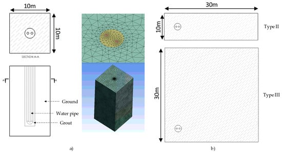
Figure 2.
(a) Geometry (out of scale) and mesh for borehole Type I model; (b) geometry for boreholes Type II and III.
As seen in Figure 2, all three domains are present on the geometry (ground, grout, and water) and they were all modelled on the Computational Fluid Dynamics (CFD) software. It is important to note that the domain has a rectangular shape only for the sake of simplification and ease of modelling in the CFD platform, as the shape allows for the boundary conditions to be applied simulating a full borehole grid. A perfect coupling was assumed on both the ground–grout interface and on the grout–water interface. It was also assumed that there is no transfer of mass through the interfaces, only heat. A constant mass flow rate of 0.284 kg/s was used. Several flow rates were investigated for turbulent flows in the pipe and 0.284 kg/s was chosen for its good energy efficiency ratio (EER). The EER is a measure of the heating capacity of a system in relation to its necessary parasitic power input. Here, such EER consists of the ratio of heat transfer rate to the pumping power. This value serves as a tool for comparing the cost-effectivity of different heating/cooling systems. The flow was assumed turbulent and modeled with the standard k-ε approach for calculation of turbulent kinetic energy and turbulent dissipation rate. This method is widely used in CFD to model a wide range of turbulent flows and was chosen here as it is a robust, computationally economical, and reasonably accurate in modeling turbulent flows in practical engineering calculations. The bottom boundary of the ground was considered isothermal at the initial ground temperature (i.e., initial T0 = 10 °C assumption for the virgin ground temperature was selected). The lateral outer walls were considered symmetric (to reflect the periodicity of the system), and the top wall was assumed to be insulated. The symmetric boundary is appropriate to simulate an individual borehole inside the grid as it fixes the gradient normal to these walls to be zero and prevents these walls to act as heat sinks (or heat sources). To analyze the distinct borehole types, displayed in Figure 3, the domain boundary was extended in the direction where no neighboring borehole exists, and this sufficiently far away wall was considered to be isothermal with a temperature equal to the bottom wall as can be also seen on Figure 2. For these two diverse types of borehole, the lateral distance was increased from half of the center-to-center distance of the bores (5 m) to 25 m which after examination of several distances demonstrated to be far enough for the wall not to affect the results or act as a heat sink.
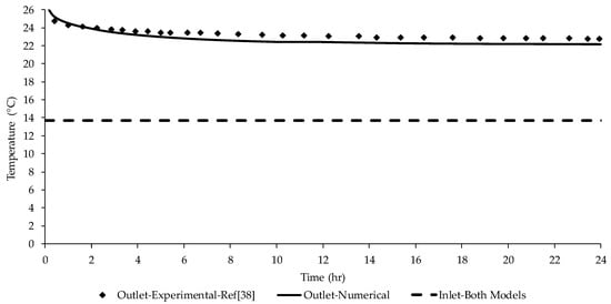
Figure 3.
Model validation with experimental thermal storage work in Reference [38].
Hence, after modeling and simulation of the unitary borehole, the results were analyzed to determine the specifications of the borehole grid necessary to sustain the seasonal thermal storage needs of Kwadacha. It is worth noting that throughout the paper the boreholes were assumed to be operating in parallel, allowing for the use of the same inlet temperature for each borehole.
4. Model Validation
To validate the numerical model used in this paper, its results were compared with the experimental result of Reference [38]. To establish a common ground with the experimental work, the proposed borehole thermal storage system was re-scaled to the size of the lab experiment explained in Reference [38]. Re-scaling of the model also included the timeframe of the experimental work providing a comparably higher data resolution of the heat storage process at a shorter timeframe.
Figure 3 depicts the comparison between the experimental data from Reference [38] and the results generated from the proposed thermal storage model. As shown in Figure 3, a good agreement can be observed between the proposed model and the experimental data with the maximum relative error found to be 4%. It is worthwhile to note that both numerical simulation and experimental test reached the steady state operation within the time shown. This agreement not only proves the fact that the proposed model represents the reality with a good match, but also it implies that the proposed model can offer a high-resolution assessment of the initial transient thermal response of the system.
5. Results and Discussion
A borehole design with the specifications listed in Table 3 was modeled and tested for various circulating water temperatures to observe the heat stored in the ground. Each borehole’s physical domain will be affected in a different way based on its distinctive operating conditions and characteristics. However, simulations showed that boreholes with the same number of immediate neighbors, would behave similarly and it would be an adequate simplification to implement that their heat transfer rates are the same (with an average relative error smaller than 1% and maximum relative error smaller than 5%). The three unitary borehole models, shown in Figure 4, were defined to represent each one of the three distinctive borehole positions on the grid. The schematic view of these three distinctive bore types, referred to as Type I (8 neighbors), II (5 neighbors), and III (3 neighbors), is also shown in Figure 3. The model was used to simulate individual boreholes on the grid and their results were inferred for all the other boreholes with the same number of neighbors based on the assumption. Each model was run separately for heat injection and extraction scenarios and the results were combined. Calculations have shown that a 6 × 6 grid installation with 16 Type I boreholes, 16 Type II, and 4 Type III can handle the overall storage capacity required for the case studied here. Note that, pipeline wall thickness and related thermal properties are neglected in the simulation as they have a relatively smaller impact on overall heat transfer over the long-run. However, under normal circumstances, it is very common to see high-density-polyethylene (HDPE) pipes in real-life geothermal applications. They are widely preferred due to their higher duration and flexibility.
Table 3.
Borehole design parameters.
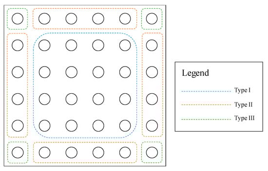
Figure 4.
Schematic of the 6 × 6 borehole grid selected with different borehole types highlighted.
Table 4 summarizes the energy storage capacities for each individual type of borehole considered for the system. As can be seen in Table 4, the position of the borehole directly influences its performance. The less neighbors it has, the more energy it is able to store. However, it is also less likely to contribute to the energy extraction (discharge), as heat can be more easily conducted away from its surrounding ground. The heat conducted from the ground to the further boundaries is very severe for Type III. Interestingly, as a result of this heat dissipation effect, Type III bores keep injecting some heat into the ground even during the extraction period. Despite that, the targeted 1.19 GWh of thermally available waste energy is well matched with the borehole grid storage capacity, with 12% contingency of the overall available heat (i.e., 1.33 GWh @ 12% contingency).
Table 4.
Results for energy storage (+ sign) for 6 months and extraction (− sign) for 6 months of all three proposed types of boreholes after thermal pre-conditioning (averaged values over 6 years).
As explained previously, to sustain the system effectiveness and provide the necessary level of heat to the residential areas, the ground was left to be thermally preconditioned with heat injection for three years. Having waited for this thermal pre-conditioning period, the heat extraction process was performed for every six months (i.e., winter) which was then followed by a six-month re-injection of hot water (i.e., summer). Figure 5 illustrates the ground thermal response and average ground temperature for different heat injection scenarios (i.e., increasing inlet temperatures classified as scenario A to D). The average ground temperature for Type I borehole grows with increasing injection temperature, as shown in Figure 5. To shorten the time needed for ground thermal pre-conditioning, the 80 °C water injection scenario is selected. This temperature is completely feasible as this is a closed system where the water is circulated from the reservoir to the heat recovery units, then to the boreholes and finally back to the reservoir. Temperature of the water on the reservoir is then expected to be close to the boreholes’ outlet temperature, i.e., approximately 72–74 °C which is then brought back to 80 °C before the injection via the heat available (275 kW) at the exhaust of the generators.
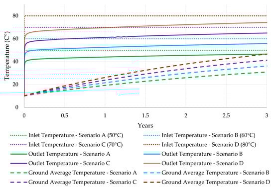
Figure 5.
Ground Temperatures of inlet and outlet water and average ground temperature during the ground pre-conditioning period.
Figure 6 and Figure 7 investigate the 80 °C water injection scenario in more detail for the different borehole types. Both graphs show a declining flux for the first three years while the ground is pre-conditioned with heat and a periodic behavior for the injection/extraction cycles. It can be noted that through the cycles the injection flux slowly decreases while the extraction one increases. This is caused by the overall accumulation of heat in the ground as less heat is extracted than the value stored (as listed on Table 4). It is important to note that, in winter, after the water receives heat in the BTES, it is circulated through the gen-set heat recovery unit to have its temperature upgraded for direct heating applications. The returning water temperature at this case is assumed to be 37 °C. These graphs also display how the performance of the borehole decays as less boreholes are present in its vicinity. As seen in Table 5. the extraction flux for the Types II and III (shown in Figure 7) are much lower than for Type I (shown in Figure 6), with Type III even presenting positive fluxes (storage of heat) during the intended extraction phase.
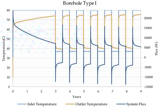
Figure 6.
Ground thermal behavior showing three years of heat injection followed by six years of seasonal cyclic thermal storage and recovery process.
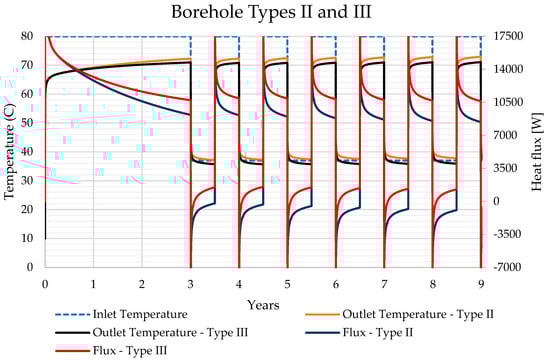
Figure 7.
Ground thermal behavior showing three years of heat injection and seasonal cyclic thermal storage and recovery process.
Table 5.
Annual heat demand of Kwadacha and system sizing details.
It is also important to evaluate the financial aspect of the proposed BTES system. This is a fundamental requirement of any borehole project, as these applications may be associated with relatively high capital costs resulting in financial deficiencies. For a proper financial analysis of the proposed BTES system, the energy demand for the community was investigated and sized. Table 5 is briefly discussing the communal energy demand of Kwadacha based on the information published by Stat Canada [39]. According to Table 5, the achievable overall annual savings are $48,150 which is a sizeable portion of the heating costs of this community, given the small number of its population.
As underlined in Table 5, it is worth investigating the potential for carbon tax savings, as they vary based on the amount of the fossil fuel burned and size of the system. As stated by the Government of British Columbia, the current carbon taxes imposed in this province is CAD $ 35/tonne eCO2 and it is estimated to be raised to CAD $ 50/tonne eCO2 by 2021 [40]. The impact of carbon taxes on similar geothermal projects is extensively discussed in Ghoreishi-Madiseh and Kuyuk [41]. Carbon tax savings associated with the current project account for 7.1% of the overall savings and are included in the financial analysis.
On the other hand, capital size of the project is usually site-specific and requires appraisal. As calculated in Table 6, for this study, the capital expenditure (CAPEX) estimation is made based on the sources available in literature such as Gupta [42]. Here, it is important to highlight that Gupta’s [42] cost model includes all the main costs associated with sinking a meter of geothermal borehole (i.e., all the costs including but not limited to fitting, excavating, pipelining etc. per meter.). Table 6 summarizes the Capital Expenditure (CAPEX) estimation of the present project based on the listed cost estimations in Gupta [42].
Table 6.
Payback period of the proposed project.
Comparing the potential savings of Table 5 and the appraised costs of Table 6, it is found that the simple payback period for the case study is 4.90 years (as shown in Table 6). In a more general sense, thermal energy storage systems relying on a coupling between low-grade heat source (e.g., solar energy as heat source) and an underground seasonal thermal energy storage (e.g., borehole thermal energy storage) have very high payback periods [43], due to relatively lower savings. However, in the proposed system, the source of thermal energy is the waste heat from diesel exhaust which has comparatively higher-grade thermal value and can be recovered at much lower costs. Therefore, the coupling between such high-grade waste heat source and an underground seasonal thermal energy storage (e.g., rockpile) system offers a viable opportunity for much shorter payback period [44]. This certainly makes the payback period of this proposed system short enough for it to be feasible. Bearing in mind that the aim of this study was to provide a sustainable and green solution for space heating in a remote community which is solely dependent on diesel generators for power generation instead of investigating for viable alternative sources for power, even if there is any.
6. Conclusions
The majority of the remote communities located in cold climates, such as Canada and Norway, are using diesel generators to sustain their energy provision. In some of the most modern systems, coupled heat exchangers are used to recover the waste heat from generator jacket water during the winter season. However, utilization of this waste heat is usually neglected during the summer period as the heat demand by the nearby community is low. As an environmentally-friendly solution to this issue, a storage system namely borehole thermal energy storage (BTES) was proposed and introduced. Furthermore, similar thermal storage systems were also investigated and discussed briefly in this work.
In this regard, the proposed system was briefed and studied by aiming to help remote communities with applicable generation systems in saving from their carbon emissions and financials of their energy provision framework. For the scientific validation of the proposed storage technique, a representative 3-dimensional model of the concept was constructed on SolidWorks and transferred to a commercially available CFD software named ANSYS/Fluent. Then the model was discretized, meshed, and solved numerically. Also, several other sensitivity runs were conducted to make sure the optimum temperature profile for water injection was selected. In delivery of this work, a remote community in British Columbia, Canada was chosen as an example community and the source of data was briefly introduced. It is also worthwhile to mention that all the runs and calculations conducted in this study are based on real-life data collected from official sources (i.e., NRCan). Consequently, the long-term performance of the BTES and thermal response of the ground was tested and presented. It was shown that annually 350 MWh of energy can be stored and provided by the BTES system.
Also, a financial estimation was carried out to evaluate costs versus savings and the payback period. It was found that for the showcased community of 127 residents, approximately CAD $48,000 savings can be achieved. It was also shown that with the deployment of the proposed 6 × 6 BTES system, this small off-grid community can lower its carbon foot print by approximately 90 tons of CO2 per year. Finally, it was estimated that the proposed project pays the associated CAPEX in less than five years.
Author Contributions
Conceptualization, S.A.G.-M. and A.S.; Methodology, S.A.G.-M., M.A.R.d.B., A.F.K. and D.B.; Software, A.F.K., M.A.R.d.B. and D.B.; Validation, M.A.R.d.B. and S.A.G.-M.; Formal Analysis, A.F.K., Z.T., M.A.R.d.B. and D.B.; Investigation, A.F.K., M.A.R.d.B. and D.B.; Resources, M.A.R.d.B., A.F.K.; Data Curation, M.A.R.d.B., A.F.K. and D.B.; Writing—Original Draft Preparation, A.F.K., Z.T., M.A.R.d.B. and D.B.; Writing—Review & Editing, M.A.R.d.B., A.F.K., Z.T. and D.B.; Visualization, A.S., Z.T., M.A.R.d.B. and D.B.; Supervision, S.A.G.-M.; Project Administration, S.A.G.-M. and A.S.; Funding Acquisition, S.A.G.-M. and A.S.
Funding
The APC was funded by the University of Stavanger.
Conflicts of Interest
The authors declare no conflict of interest. The funders had no role in the design of the study; in the collection, analyses, or interpretation of data; in the writing of the manuscript, and in the decision to publish the results.
References
- Knowles, J. Power Shift: Electricity for Canada’s Remote Communities, (September), 65. 2016. Available online: http://www.conferenceboard.ca/e-library/abstract.aspx?did=8249 (accessed on 10 April 2018).
- Hossain, S.N.; Bari, S. Waste heat recovery from exhaust of a diesel generator set using organic fluids. Procedia Eng. 2014, 90, 439–444. [Google Scholar] [CrossRef]
- Johnson, V.H. Heat-Generated Cooling Opportunities in Vehicles. Adv. Mater. 2002, 6. [Google Scholar] [CrossRef]
- Teng, H.; Regner, G.; Cowland, C. Waste Heat Recovery of Heavy-Duty Diesel Engines by Organic Rankine Cycle Part I: Hybrid Energy System of Diesel and Rankine Engines. SAE Tech. Paper 2007, 1–537. [Google Scholar] [CrossRef]
- Al-Rabghi, O.M.; Beirutty, M.; Akyurt, M.; Najjar, Y.; Alp, T. Recovery and utilization of waste heat. Heat Recovery Syst. CHP 1993, 13, 463–470. [Google Scholar] [CrossRef]
- Hossain, S.N.; Bari, S. Waste heat recovery from the exhaust of a diesel generator using Rankine Cycle. Energy Convers. Manag. 2013, 75, 141–151. [Google Scholar] [CrossRef]
- Wang, T.; Zhang, Y.; Peng, Z.; Shu, G. A review of researches on thermal exhaust heat recovery with Rankine cycle. Renew. Sustain. Energy Rev. 2011, 15, 2862–2871. [Google Scholar] [CrossRef]
- Hung, T.C.; Shai, T.Y.; Wang, S.K. A review of organic rankine cycles (ORCs) for the recovery of low-grade waste heat. Energy 1997, 22, 661–667. [Google Scholar] [CrossRef]
- Dolz, V.; Novella, R.; García, A.; Sánchez, J. HD Diesel engine equipped with a bottoming Rankine cycle as a waste heat recovery system. Part 1: Study and analysis of the waste heat energy. Appl. Therm. Eng. 2012, 36, 269–278. [Google Scholar] [CrossRef]
- Noie-Baghban, S.H.; Majideian, G.R. Waste heat recovery using heat pipe heat exchanger (HPHE) for surgery rooms in hospitals. Appl. Therm. Eng. 2000, 20, 1271–1282. [Google Scholar] [CrossRef]
- Yang, F.; Yuan, X.; Lin, G. Waste heat recovery using heat pipe heat exchanger for heating automobile using exhaust gas. Appl. Therm. Eng. 2003, 23, 367–372. [Google Scholar] [CrossRef]
- Surwase, P.B.; Farkade, H.S. Waste Heat Recovery From The Exhaust of a Diesel Engine Using Parallel Flow Shell and Tube Heat Exchanger. Int. J. Mech. Prod. Eng. 2016, 4, 150–153. [Google Scholar]
- Lin, C. Capture of Heat Energy from Diesel Engine Exhaust; University of Alaska: Fairbanks, AK, USA, 2008. [Google Scholar]
- Pandiyarajan, V.; Chinna Pandian, M.; Malan, E.; Velraj, R.; Seeniraj, R.V. Experimental investigation on heat recovery from diesel engine exhaust using finned shell and tube heat exchanger and thermal storage system. Appl. Energy 2001, 88, 77–87. [Google Scholar] [CrossRef]
- Baker, C.; Vuppuluri, P.; Shi, L.; Hall, M. Model of heat exchangers for waste heat recovery from diesel engine exhaust for thermoelectric power generation. J. Electron. Mater. 2012, 41, 1290–1297. [Google Scholar] [CrossRef]
- Kumar, C.R.; Sonthalia, A.; Goel, R. Experimental study on waste heat recovery from an internal combustion engine using thermoelectric technology. Therm. Sci. 2011, 15, 1011–1022. [Google Scholar] [CrossRef]
- Orr, B.; Akbarzadeh, A.; Mochizuki, M.; Singh, R. A review of car waste heat recovery systems utilising thermoelectric generators and heat pipes. Appl. Therm. Eng. 2016, 101, 490–495. [Google Scholar] [CrossRef]
- Erlund, R.; Zevenhoven, R. Hydration of Magnesium Carbonate in a Thermal Energy Storage Process and Its Heating Application Design. Energies 2018, 11, 170. [Google Scholar] [CrossRef]
- Fisch, M.N.; Guigas, M.; Dalenbäck, J.-O. A review of large-scale solar heating systems in Europe. Sol. Energy 1998, 63, 355–366. [Google Scholar] [CrossRef]
- Lanahan, M.; Tabares-Velasco, P.C. Seasonal thermal-energy storage: A critical review on BTES systems, modeling, and system design for higher system efficiency. Energies 2017, 10. [Google Scholar] [CrossRef]
- Socaciu, L.G. Seasonal sensible thermal energy storage solutions. Leonardo Electron. J. Pract. Technol. 2011, 10, 49–68. [Google Scholar]
- Pavlov, G.K.; Olesen, B.W. Seasonal Ground Solar Thermal Energy Storage—Review of Systems and Applications. ISES Sol. World Congr. 2011, 2011, 515–525. [Google Scholar] [CrossRef]
- Dincer, I.; Rosen, M. Thermal Energy Storage: Systems and Applications; John Wiley & Sons: Chichester, UK, 2011. [Google Scholar]
- Bauer, D.; Marx, R.; Nußbicker-Lux, J.; Ochs, F.; Heidemann, W.; Müller-Steinhagen, H. German central solar heating plants with seasonal heat storage. Sol. Energy 2010, 84, 612–623. [Google Scholar] [CrossRef]
- Thorshaug Andresen, H.; Li, Y. Modelling the Heating of the Green Energy Lab in Shanghai by the Geothermal Heat Pump Combined with the Solar Thermal Energy and Ground Energy Storage. Energy Procedia 2015, 70, 155–162. [Google Scholar] [CrossRef][Green Version]
- Lundh, M.; Dalenbäck, J.O. Swedish solar heated residential area with seasonal storage in rock: Initial evaluation. Renew. Energy 2008, 33, 703–711. [Google Scholar] [CrossRef]
- Canadian GeoExchange Coalition, “Geothermal energy,” pp. 39–75. 2013. Available online: www.geo-exchange.ca (accessed on 12 April 2018).
- Sibbitt, B.; McClenahan, D.; Djebbar, R.; Thornton, J.; Wong, B.; Carriere, J.; Kokko, J. The performance of a high solar fraction seasonal storage district heating system–five years of operation. Energy Procedia 2012, 30, 856–865. [Google Scholar] [CrossRef]
- Chapuis, S.; Bernier, M. Seasonal Storage of Solar Energy in Borehole Heat Exchangers. Eleventh International IBPSA Conference, pp. 599–606. 2009. Available online: http://citeseerx.ist.psu.edu/viewdoc/summary?doi=10.1.1.172.4804 (accessed on 12 April 2018).
- Gagné-Boisvert, L.; Bernier, M. Integrated model for comparison of one-and two-pipe ground-coupled heat pump network configurations. Sci. Technol. Built Environ. 2018, 24, 726–742. [Google Scholar] [CrossRef]
- Mccartney, J.S.; Lu, N.; Smits, K. Storage of Solar Thermal Energy in Borehole Thermal Energy Storage Systems. In Proceedings of the IGSHPA Technical/Research Conference and Expo, Denver, CO, USA, 14–16 March 2017. [Google Scholar] [CrossRef]
- Nejad, P.E.; Badache, M.; Corcoran, A.; Bernier, M. Virtual Borehole for Thermal Response Test Unit Calibration: Test Facility and Concept Development. In Proceedings of the 2nd IGSHPA Research Track, Stockholm, Sweden, 18–20 September 2018. [Google Scholar] [CrossRef]
- Welsch, B.; Göllner-Völker, L.; Schulte, D.O.; Bär, K.; Sass, I.; Schebek, L. Environmental and economic assessment of borehole thermal energy storage in district heating systems. Appl. Energy 2018, 216, 73–90. [Google Scholar] [CrossRef]
- Mcdaniel, B.; Kosanovic, D. Modeling of combined heat and power plant performance with seasonal thermal energy storage. J. Energy Storage 2016, 7, 13–23. [Google Scholar] [CrossRef]
- Xu, J.; Wang, R.Z.; Li, Y. A review of available technologies for seasonal thermal energy storage. Sol. Energy 2014, 103, 610–638. [Google Scholar] [CrossRef]
- Natural Resources Canada. The Atlas of Canada. Remote Communities Energy Database. 2017. Available online: http://atlas.gc.ca/rced-bdece/en/index.html (accessed on 18 April 2018).
- Bernier, M.A. Closed-Loop Ground-Coupled Heat Pump Systems. ASHRAE J. 2006, 48, 12–25. [Google Scholar]
- Ghoreishi-Madiseh, S.A.; Hassani, F.; Abbasy, F. Numerical and experimental study of geothermal heat extraction from backfilled mine stopes. Appl. Therm. Eng. 2015, 90, 1119–1130. [Google Scholar] [CrossRef]
- Statistics Canada. Household and the Environment: Energy Use (Archives). 2007. Available online: https://www150.statcan.gc.ca/n1/pub/11-526-s/2010001/part-partie1-eng.htm (accessed on 18 July 2018).
- Government of BC. Environmental Protection & Sustainability. British Columbia’s Revenue-Neutral Carbon Tax. Available online: http://www2.gov.bc.ca/gov/content/environment/climate-change/planning-and-action/carbon-tax (accessed on 18 April 2018).
- Ghoreishi-Madiseh, S.A.; Kuyuk, A.F. A techno-economic model for application of geothermal heat pump systems. Energy Procedia 2017, 142, 2611–2616. [Google Scholar] [CrossRef]
- Gupta, H. (Ed.) Encyclopedia of Solid Earth Geophysics; Springer Science & Business Media: Dordecht, The Netherlands, 2011; ISBN 978-90-481-8701-0. [Google Scholar]
- Karacavus, B.; Can, A. Thermal and economical analysis of an underground seasonal storage heating system in Thrace. Energy Build. 2009, 41, 1–10. [Google Scholar] [CrossRef]
- Ghoreishi-Madiseh, S.A.; Safari, A.; Amiri, L.; Baidya, D.; Brito, M.A.R.; Kuyuk, A.F. Investigation of viability of seasonal waste heat storage in rock piles for remote communities in cold climates. Energy Procedia. 2019. accepted. [Google Scholar]


© 2019 by the authors. Licensee MDPI, Basel, Switzerland. This article is an open access article distributed under the terms and conditions of the Creative Commons Attribution (CC BY) license (http://creativecommons.org/licenses/by/4.0/).