Article

System Design and Energy Management for a Fuel Cell/Battery Hybrid Forklift

1
Key Laboratory of Electronic Information (Southwest Minzu University), State Ethnic Affairs Commission, Chengdu 610041, China
2
School of Electrical Engineering, Southwest Jiaotong University, Chengdu 610031, China
3
Power and Energy Group, University of Queensland, Brisbane, QLD 4072, Australia
*
Author to whom correspondence should be addressed.
Energies 2018, 11(12), 3440; https://doi.org/10.3390/en11123440
Submission received: 12 November 2018 / Revised: 30 November 2018 / Accepted: 6 December 2018 / Published: 8 December 2018
(This article belongs to the Special Issue Fuel Cell Systems Design and Control)

Abstract

:
Electric forklifts, dominantly powered by lead acid batteries, are widely used for material handling in factories, warehouses, and docks. The long charging time and short working time characteristics of the lead acid battery module results in the necessity of several battery modules to support one forklift. Compared with the cost and time consuming lead acid battery charging system, a fuel cell/battery hybrid power module could be more convenient for a forklift with fast hydrogen refueling and long working time. In this paper, based on the characteristics of a fuel cell and a battery, a prototype hybrid forklift with a fuel cell/battery hybrid power system is constructed, and its hardware and software are designed in detail. According to the power demand of driver cycles and the state of charge (SOC) of battery, an energy management strategy based on load current following for the hybrid forklift is proposed to improve system energy efficiency and dynamic response performance. The proposed energy management strategy will fulfill the power requirements under typical driving cycles, achieve reasonable power distribution between the fuel cell and battery and, thus, prolong its continuous working time. The proposed energy management strategy is implemented in the hybrid forklift prototype and its effectiveness is tested under different operating conditions. The results show that the forklift with the proposed hybrid powered strategy has good performance with different loads, both lifting and moving, in a smooth and steady way, and the output of the fuel cell meets the requirements of its output characteristics, its SOC of battery remaining at a reasonable level.

1. Introduction

Forklifts are indispensable and widely used in factories, warehouses, docks, and distribution centers as goods handling vehicles. Electric forklifts, dominantly powered by lead acid batteries, have wide application in indoor operations and other conditions which have strict requirements, such as medicine and food industries. The weaknesses of lead acid battery modules are a long charging time and a short working time which can result in an increase of the user-cost under a multi-shift working condition [1,2]. Hydrogen/oxygen fuel cells, as a new energy device, have become the most promising choice for the energy of the vehicles due to its cleanliness, safety, sustainability, high efficiency, and high energy conversion efficiency [3,4,5,6]. The maximum theoretical efficiency of hydrogen/oxygen fuel cells is 83% [7], and the general efficiency is 40–60% [8]. The calculation of efficiency conversion and the polarization plot of typical losses for a hydrogen/oxygen fuel cell are shown in Equations (2.1)–(2.18) and Figure 2.1 in [7]. Forklift manufacturers, such as Crown, Plug Power, and Raymond, have constructed pure fuel cell electric forklifts, obtaining somewhere in the performance evaluation of hydrogen fuel cell forklifts, fuel reloading time, and forklift design [9,10,11,12]. However, the pure fuel cell forklift has some disadvantages, such as a large power configuration, high cost, and slow dynamic response, which cannot meet the requirements when the forklift is in operation in some special conditions.
In this paper, a fuel cell/battery hybrid forklift system is constructed with the combination of the strengths of the fuel cells and batteries, its hardware and software in each functional unit are designed in detail and, finally, a hybrid forklift prototype is successfully made. With the detailed analysis of output characteristics and energy flow of the fuel cell and battery, a load current following the energy management strategy is proposed to realize the management and distribution of the fuel cell/battery hybrid forklift energy so as to improve the system energy efficiency, dynamic response performance, and extend the life of the fuel cell. The experimental results prove that the proposed strategy is practical and effective, as it can fully meet the power demand under operating conditions and achieve stable output of the fuel cell. However, the output power of the fuel cell does not change with respect to the load and the SOC of the battery is maintained at a reasonable level.

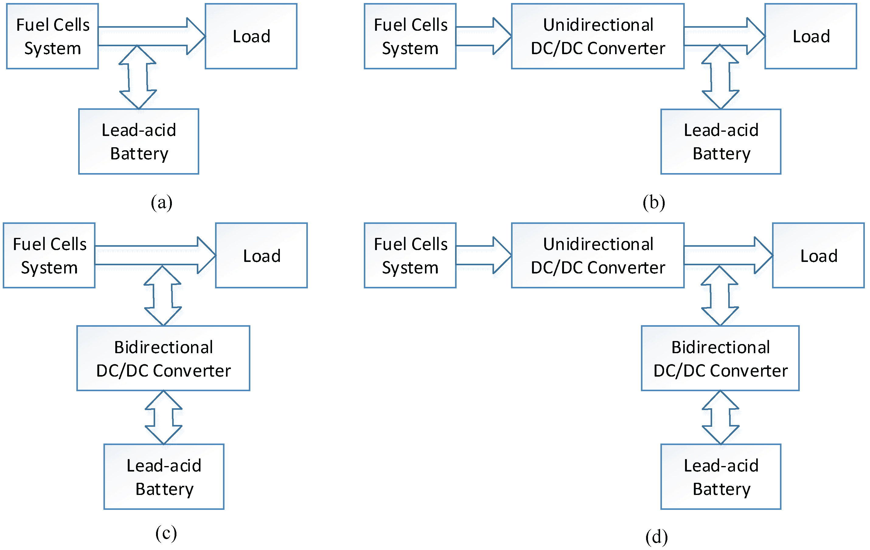
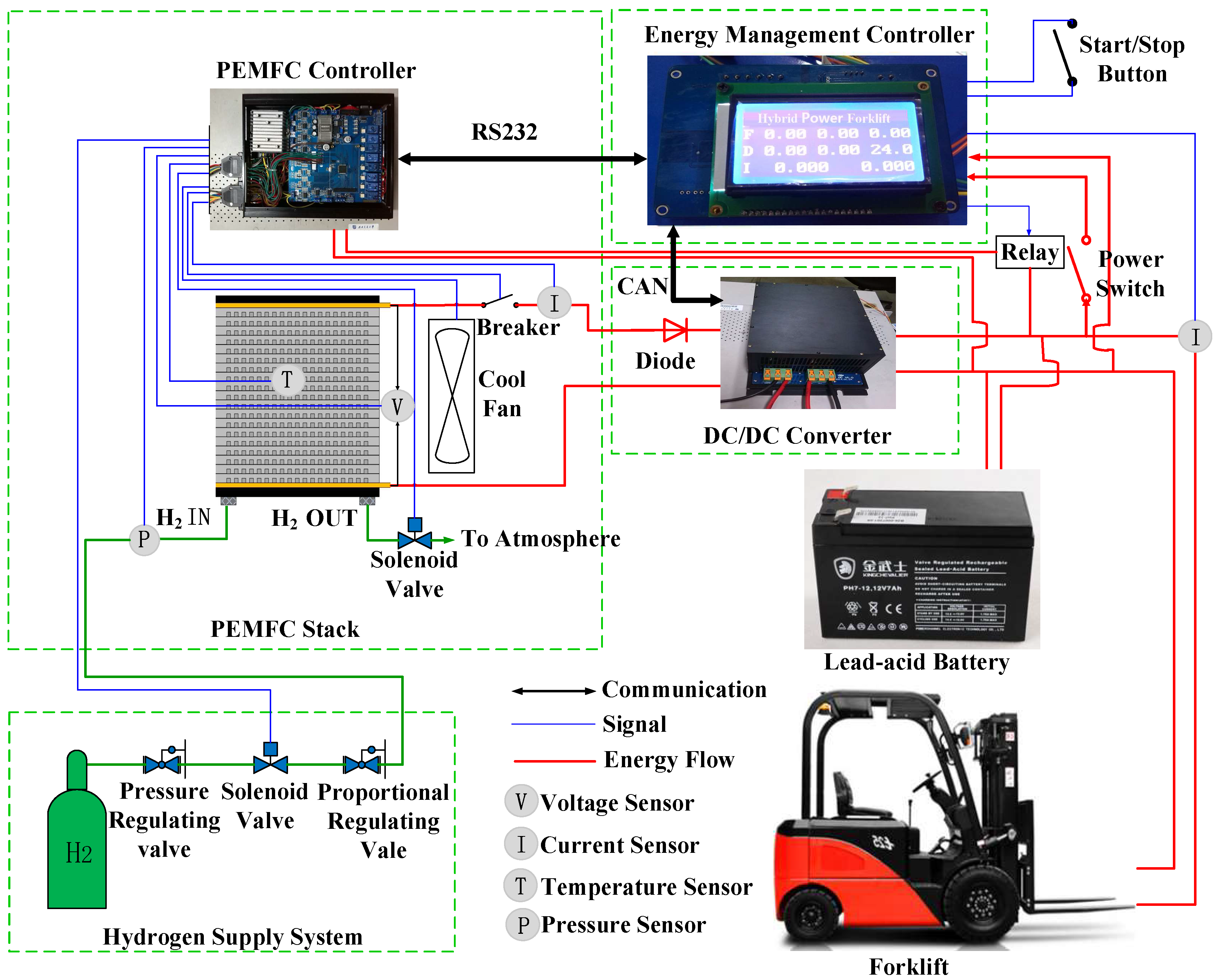
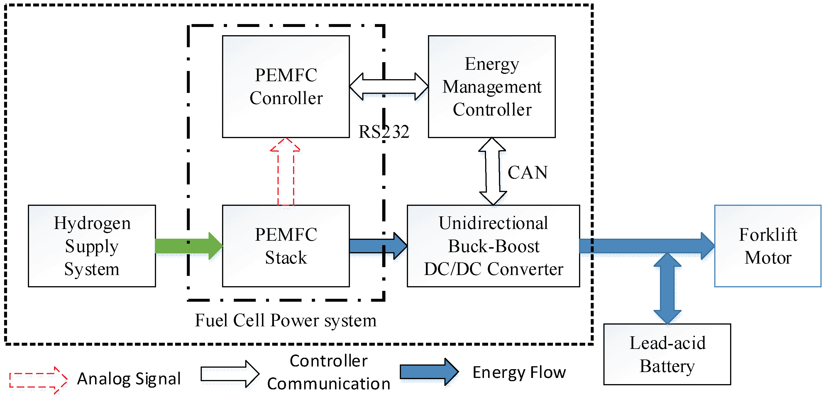
2. Topology of the Fuel Cell/Battery Hybrid Power System

The power system of a pure fuel cell has the disadvantages of a large power configuration, slow dynamic response, and wide range of output voltage variation. In order to overcome these shortcomings, researchers proposed a fuel cell hybrid system [13,14]. The fuel cell hybrid system is an electric-electric hybrid system. According to the different connection modes of the fuel cell and auxiliary power battery systems, the topology is shown in Figure 1.
Figure 1a is a relatively simple topology of a hybrid power system [15]. The fuel cell and the battery systems are directly connected to the load, and the bus voltage will be determined by the battery terminal voltage. In this topology, the voltage level of the fuel cell and the battery is determined by the rated voltage of the load. Only when the voltage level of the DC bus is matched with the load will the system obtain the best energy and economic efficiency. In addition, according to the polarization curve of a fuel cell, the output voltage of the fuel cell changes with the output current, which is similar to the current source, with soft output characteristics and slow dynamic response. In most cases, the output voltage of a fuel cell is lower than the required voltage of the DC bus when the load changes, which makes the energy management of the hybrid power system very difficult and, hence, reduces the efficiency and reliability of the system.
The fuel cell output is connected in parallel with the battery via a unidirectional DC/DC converter to form a hybrid system as shown in Figure 1b. The structure can control the output power of the fuel cell indirectly by controlling the output current of the DC/DC converter, and solves the problem that the output voltage and power of the fuel cell are uncontrollable in Figure 1a [16]. In addition, the battery is directly connected in parallel with the DC bus in this topology, so its voltage level must be matched with the load voltage.
In Figure 1a,b, the battery is directly connected to the load, so the battery terminal voltage level is required to match with the load. In order to solve the requirements of the battery voltage level, the battery can be connected to the DC bus via a bidirectional DC/DC converter. The topology of the hybrid power system is shown in Figure 1c,d. Compared with the topology in Figure 1a, in Figure 1c, the limitation of the battery terminal voltage is overcome and the SOC of the battery can be managed [17,18]. The output power of the fuel cell can be controlled indirectly by controlling the discharge current and the output voltage of the battery. Compared with the topology in Figure 1b, in Figure 1d, the voltage of the DC bus can be stabilized within the specified range of the load, and the operation of charging and discharging, and the controlling of the output of the fuel cell, can be realized. This topological structure can achieve fuel cell and battery energy control and management well, but is relatively complicated.
In this paper, the hybrid system topology shown in Figure 1b is selected as the system structure of the fuel cell/battery hybrid forklift. It is easy for this simple structure to achieve not only the hybrid energy management, but also the charging and discharging of the battery.

3. Fuel Cell/Battery Hybrid Power System Design

3.1. Hybrid Power System Description

According to the topology shown in Figure 1b, this paper constructed the fuel cell/battery hybrid power system, shown in Figure 2, by using hydrogen supply system, proton exchange membrane fuel cell (PEMFC) stack and controller, unidirectional DC/DC controller, energy management controller, and lead-acid battery.
The hydrogen supply system provides high-purity hydrogen fuel for the fuel cell, employing 30 MPa, 20 L high-pressure hydrogen storage tanks, equipped with high- and low-pressure regulating valves, pressure indicator, pressure detecting sensor, electromagnetic valve, and other auxiliary devices. The high-pressure hydrogen storage system is shown in Figure 3. Ballard’s 1020ACS series PEMFC stack (Ballard Power Systems Inc., Burnaby, BC, Canada) is adopted for the fuel cell as a main power source for the hybrid system. The PEMFC controller receives instructions issued by the energy management controller and controls the PEMFC stack to work at the optimal power output point. The real-time state parameters of the PEMFC can be collected and uploaded to the energy management controller, and then are used as the operating parameters of the controller. The unidirectional buck-boost DC/DC converter can control the output voltage, current, and power of the PEMFC unit to improve the working performance of the PEMFC and prolong the life of the PEMFC. The lead-acid battery is the energy storage unit of the hybrid power system. When the hybrid power system is started, it is used as the auxiliary power supply of the system. When the PEMFC’s output power is insufficient, it is used as the auxiliary power source to provide power supplement for the forklift motor. The energy management system controls the PEMFC controller and the DC/DC converter in real-time according to the power demand of the forklift motor and the SOC state of the battery. Thus, it controls the output power of the PEMFC stack and the charging and discharging of the battery to realize the energy distribution and management of the hybrid system.

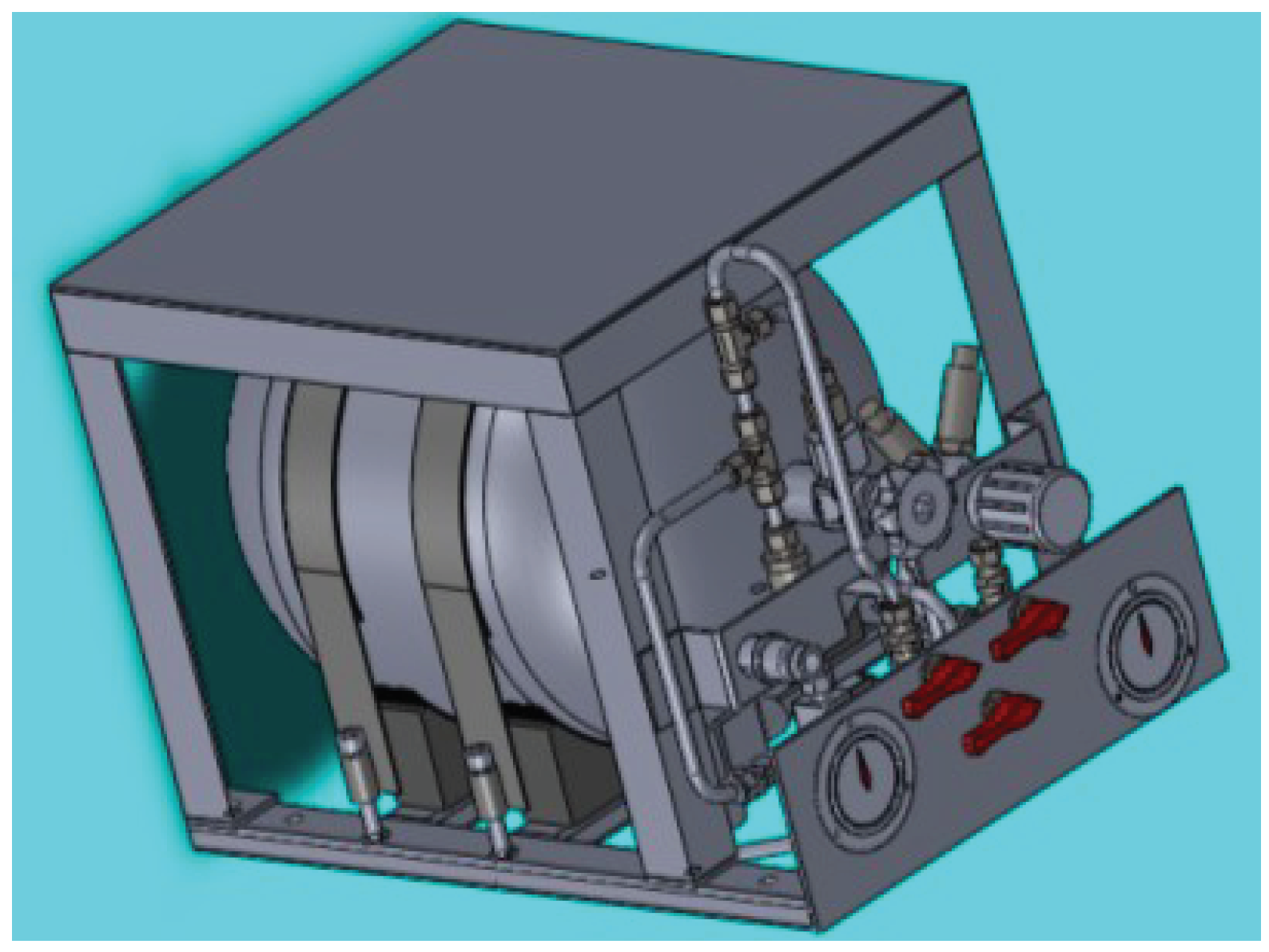
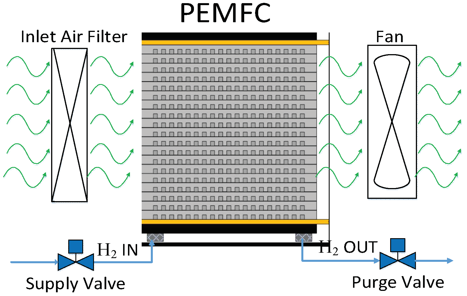
3.2. Air-Cooled PEMFC System

The fuel cell system is composed of the PEMFC stack, cooling fan, inlet solenoid valve, exhaust solenoid valve, and air filter. The PEMFC stack adopts Ballard’s air-cooled self-humidifying PEMFC stack, consisting of 56 single cells, with rated power at 2 kW, output voltage range of 30–56 V, a maximum output current of 75 A, and a maximum operating temperature of 75 °C.
The fuel for PEMFC is hydrogen and oxygen. Hydrogen enters the stack from the anode of the PEMFC stack, which undergoes a chemical reaction under the action of the catalyst to generate e, H+, and release a large amount of heat. The e migrates to the cathode via an external circuit and generates a current. H+ migrates to the cathode via the proton exchange membrane, and combines with O2 of the cathode and e to form H2O under the action of the catalyst. The remaining H2 of the reaction and the formed H2O are discharged through the exhaust gas. The PEMFC system is shown in Figure 4.

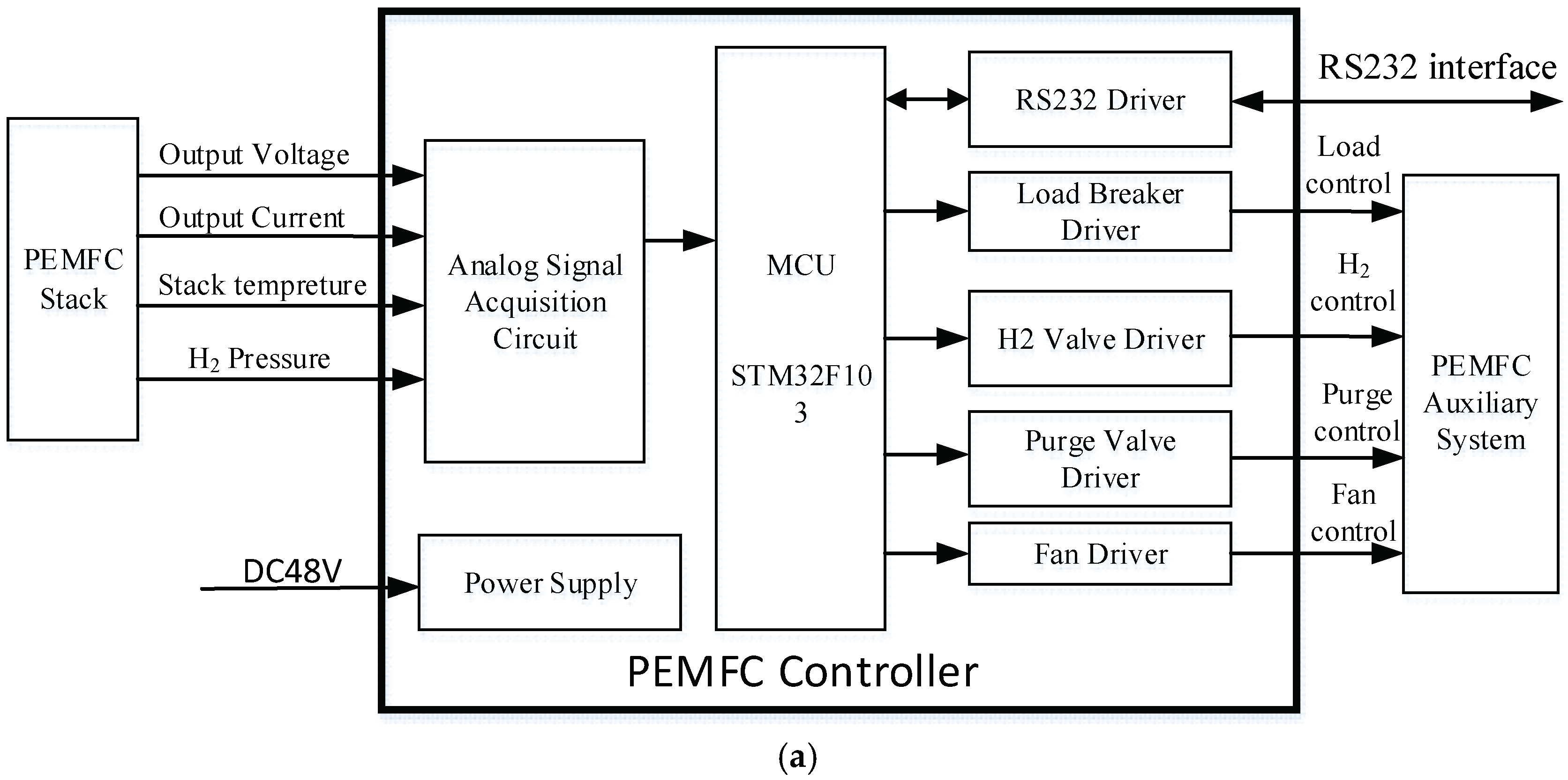
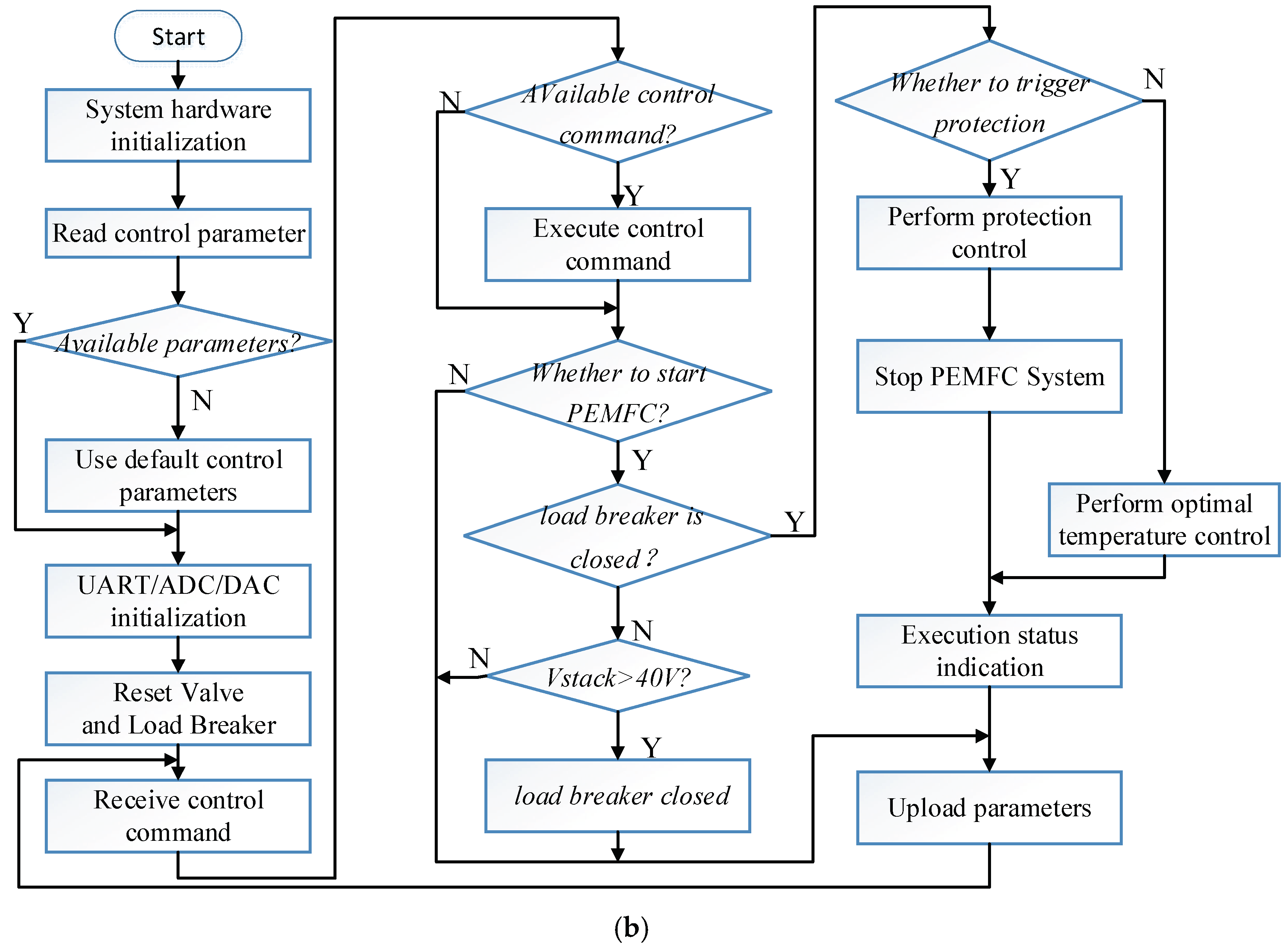
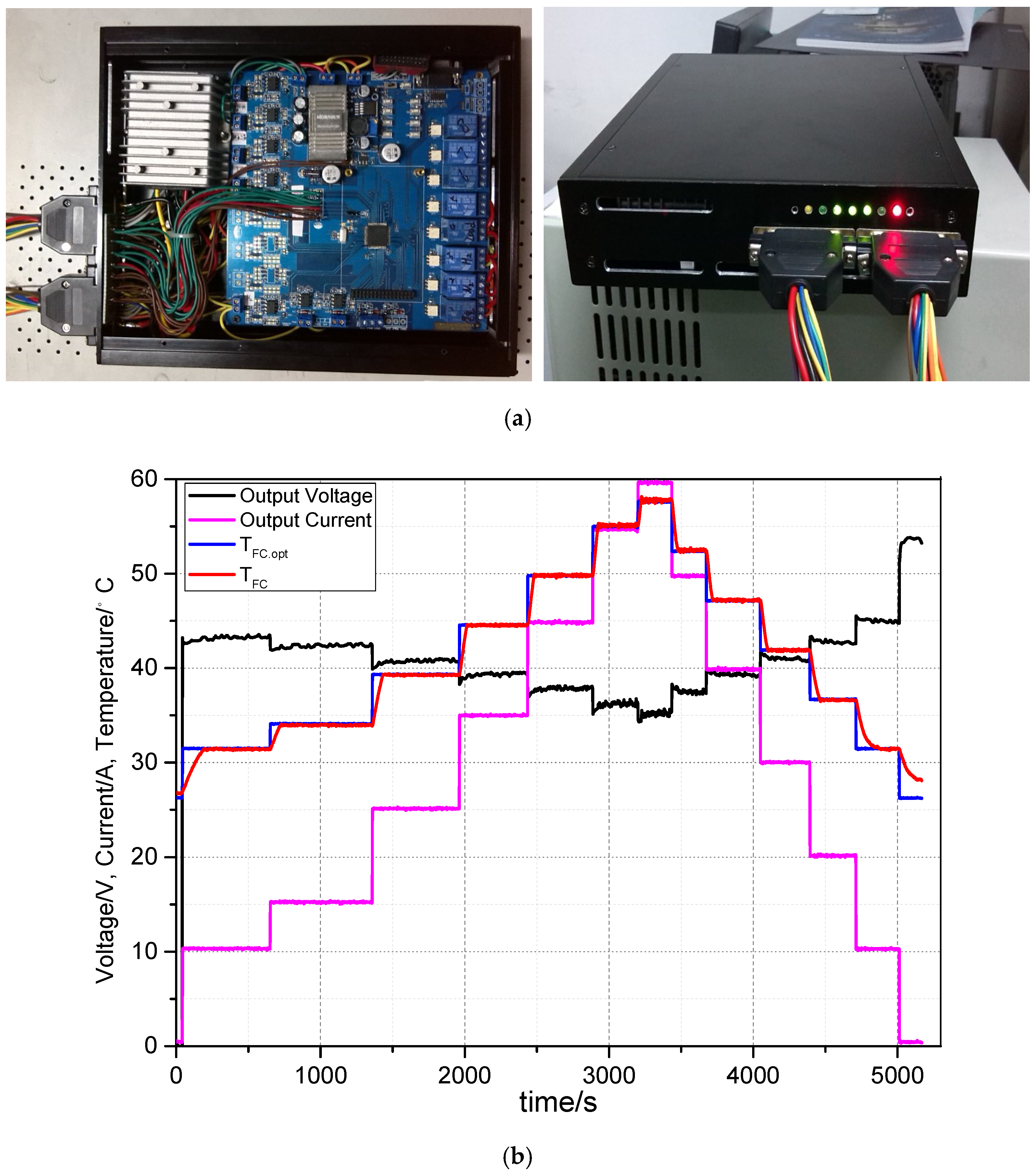
3.3. PEMFC Controller Design

The fuel cell power generation system is composed of a PEMFC stack and a PEMFC controller. The output performance of the stack is affected by some operating parameters, such as the operating temperature, air flow rate, and the exhaust gas interval. The output performance is inconsistent under different operating conditions. According to the theoretical modeling and analysis of the fuel cells in [19], the output voltage of the fuel cells can be approximately expressed as:
V cell = f ( T FC , I FC , P H 2 , P O 2 )
where TFC is the PEMFC stack temperature, IFC is the PEMFC stack output current, P H 2 and P O 2 are the hydrogen and oxygen partial pressures, respectively.
Since the cathode of the air-cooled self-humidifying PEMFC adopts a through-open structure which is directly connected to the outside air, and the P O 2 is close to a normal value. A precision proportional electrical regulating valve can be adopted at the front end of the anode inlet, which can automatically adjust the inlet H2 pressure and keep it at the set pressure point. Thus, the P H 2 can be approximated as a constant value. The output voltage of the fuel cell can be approximately simplified as:
V cell = f ( T FC , I FC )
In Equation (2), under certain conditions of output current IFC, the stack operating temperature TFC will affect the output voltage Vcell. There is an optimal operating temperature TFC.opt, which enables the output voltage and output power of the stack to be the maximum, with optimal output performance [20,21,22]. In this paper, the air-cooled PEMFC power generation controller is designed to control the operating temperature of the PEMFC stack and enable it to work near the optimal operating temperature point, with the maximum output power. The functional block diagram is shown in Figure 5.
The specific design process of the PEMFC controller is referred to in [23]. The detailed design and analysis of the realization circuit of each functional unit are given in [23]. In this paper, the PEMFC controller needs to accept the control commands of the energy management controller and controls the PEMFC stack operation according to the control instructions. The control flow chart is shown in Figure 5b [23]. Where Vstack is the output voltage of the PEMFC. The optimal temperature control algorithm adopts segmented prediction negative feedback control (SPreNFC) [22].
The real-time parameters, such as the output voltage, output current, operating temperature, and hydrogen pressure of the stack are collected by the PEMFC controller. The optimal temperature TFC.opt, which needs to be controlled at present, is calculated by using the optimal temperature formula in [22]. The SPreNFC temperature control algorithm is used to control the operation of the stack near the optimum temperature point. At the same time, according to the datasheet of the PEMFC stack, the auxiliary system of the fuel cell is controlled to maximize net power output and optimal operation performance. The PEMFC controller has an RS232 communication interface which can accept the control commands and control parameters, sent by the energy management controller, to realize the operation control of the PEMFC and upload the PEMFC state parameters to the energy management controller. The designed PEMFC controller is shown in Figure 6. Figure 6a is the PEMFC controller prototype, Figure 6b is the control response curve of the PEMFC controller to control the PEMFC stack, TFC.opt is the optimal control temperature of the PEMFC stack, and TFC is the working temperature of PEMFC stack. It can be seen from the response curve that when the output current of PEMFC changes, the PEMFC controller immediately calculates a new TFC.opt, and then controls the cooling system of the stack to make the TFC gradually reach the optimal temperature point. The output voltage reaches its maximum value and the output power is optimal. When the TFC reaches the range that is near the optimal operating temperature point, the output voltage of the PEMFC reaches the maximum value and the output power becomes optimal. For the selection of the SPreNFC control parameters, please refer to [20], and the optimal control parameters can be obtained through experimental testing.

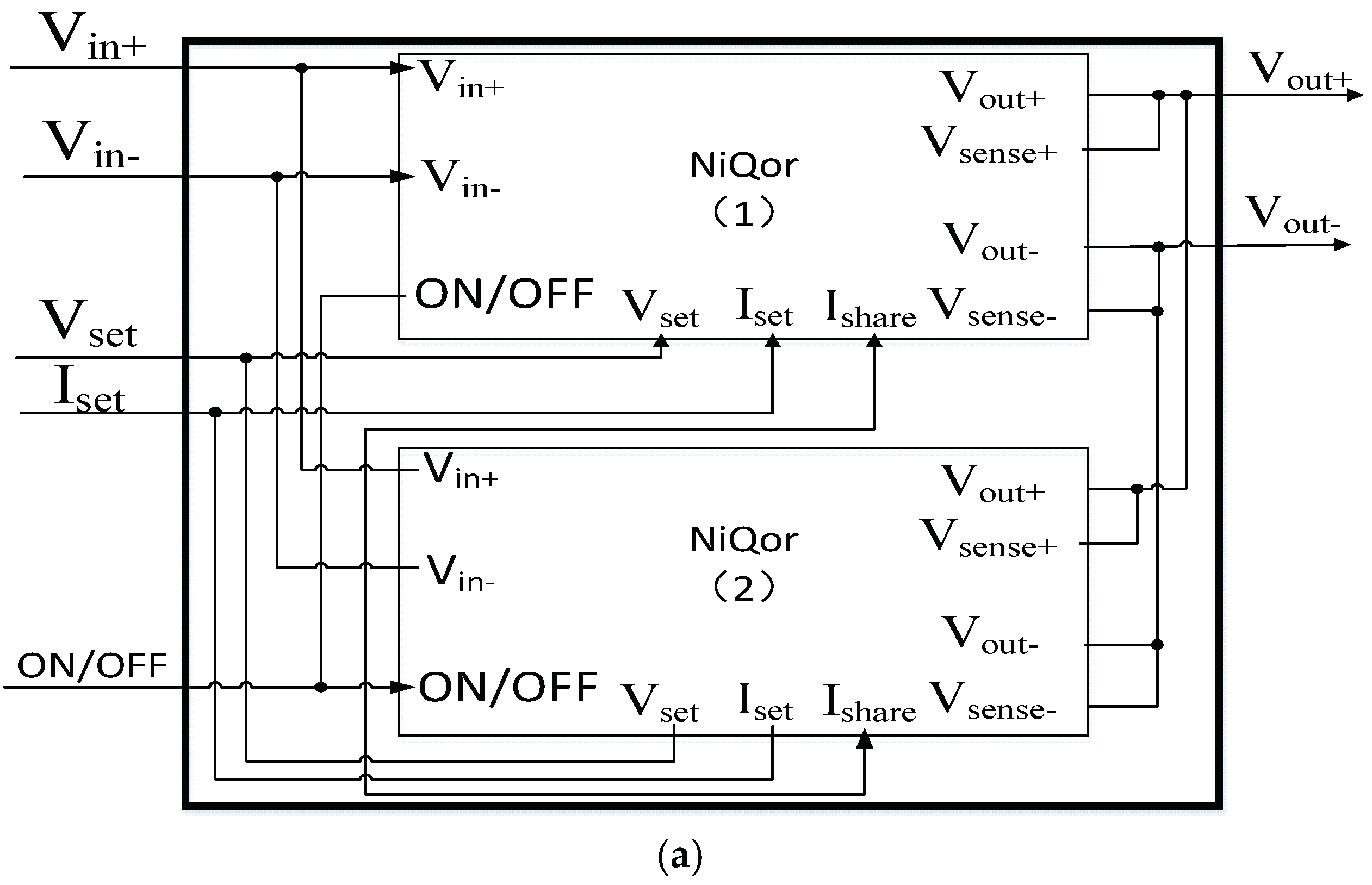
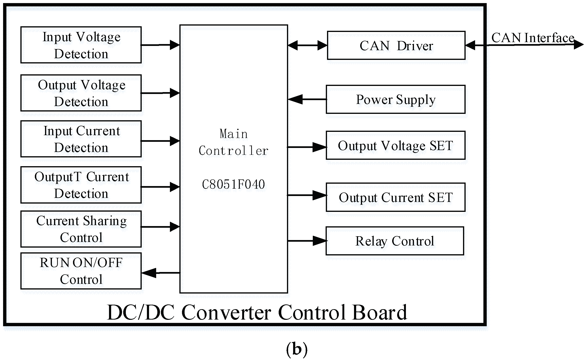
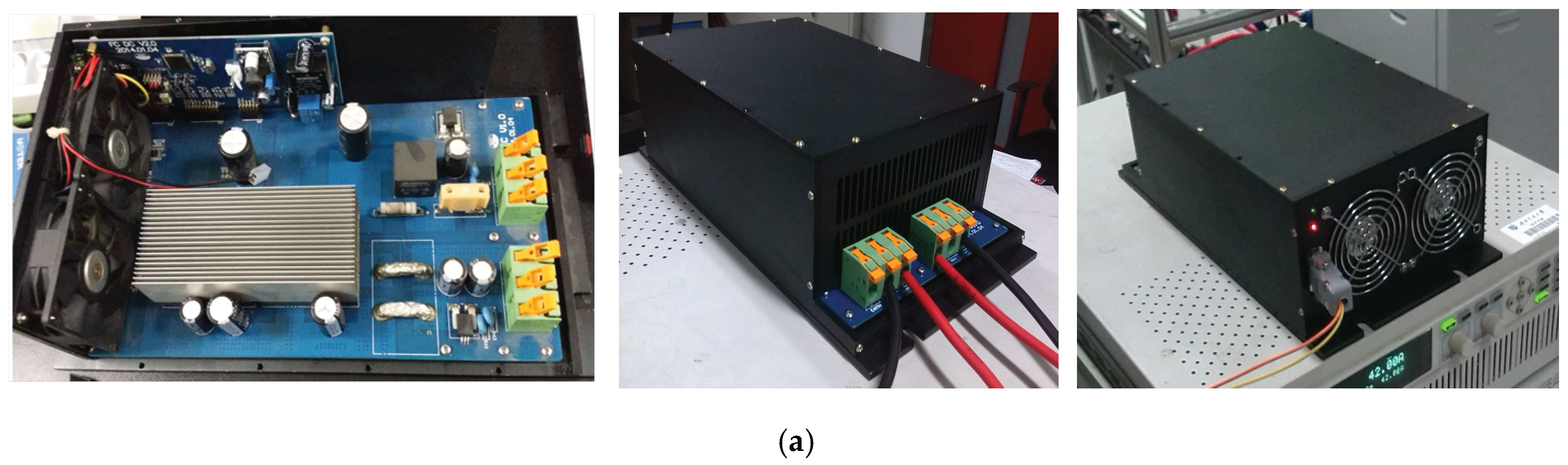
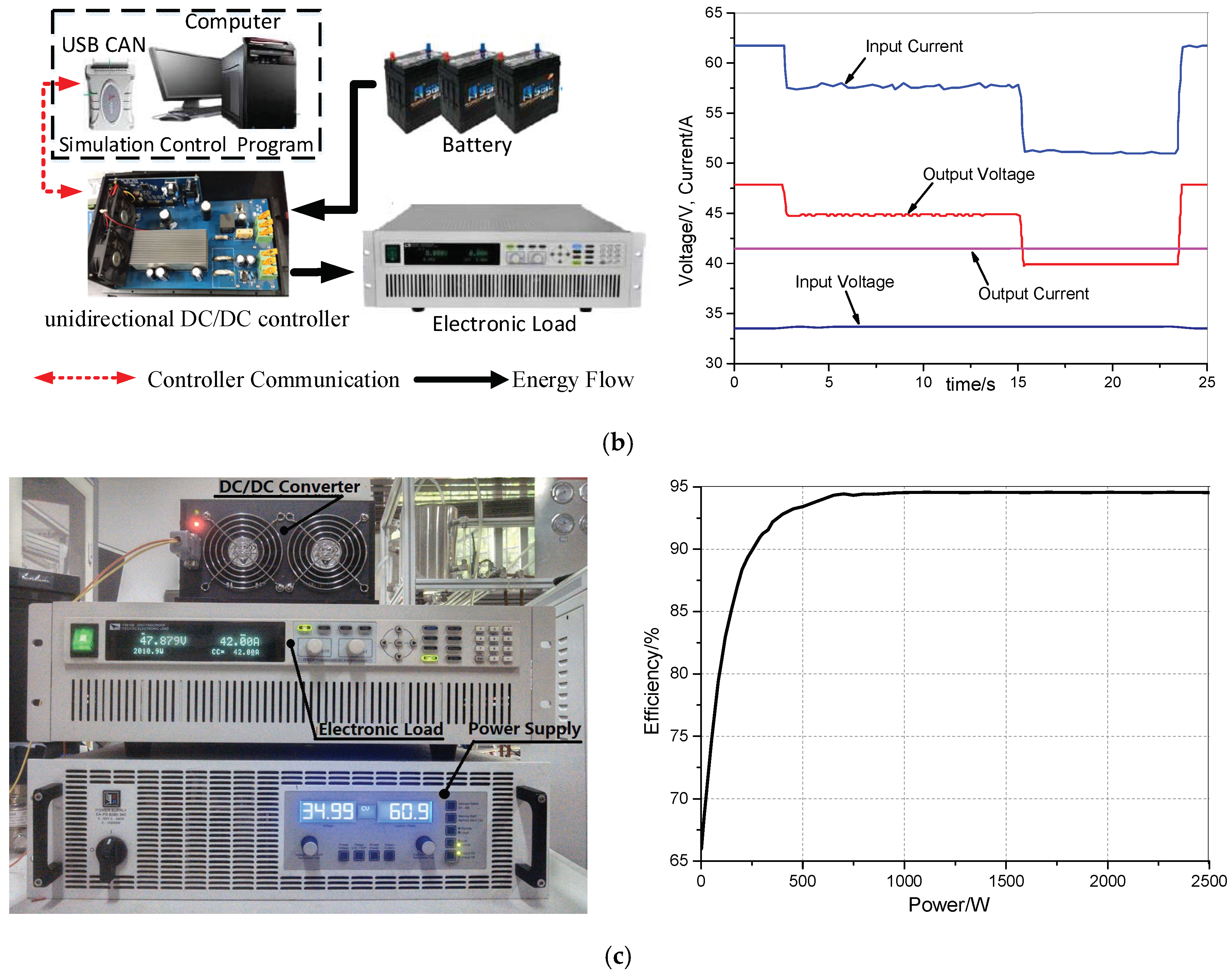
3.4. Unidirectional Buck-Boost DC/DC Converter Design

In this study, the output voltage of the PEMFC varies between 30 and 56 V. The varying range of the output voltage is large, and when the load changes, the output voltage is unstable and cannot be directly connected to the load. In order to overcome the shortcomings of the PEMFC, the output voltage needs to be connected with a unidirectional buck-boost DC/DC converter to transform the output voltage of the PEMFC into the allowable range of the battery and forklift motor. Since the rated power of the PEMFC stack is 2 kW, a DC/DC converter that can meet the maximum power output of the fuel cell stack is required.
In this paper, the DC/DC converter is designed based on the NiQor non-isolated buck-boost module (NiQor is the product model name), which is produced by SynQor, Inc., Boxborough, MA, USA. The input voltage range of the NiQor module is 9–60 V, the output voltage range is adjustable between 0 and 60 V, and the maximum input or output current is 40 A. According to the polarization curve in the PEMFC datasheet, when the PEMFC has the maximum power output, its output voltage is close to 35 V and the output current is close to 60 A. Therefore, two NiQor modules are connected in parallel, and the maximum output current can reach 80 A, which fully meets the output power requirements of the PEMFC stack.
The NiQor module has 11 control ports, which are voltage setting Vset, current setting Iset, enable control ON/OFF, current sharing control Ishare, synchronous control Syncin, voltage sensing reference positive Vsense+, voltage sensing reference negative Vsense−, input Vin+ and Vin−, and output Vout+ and Vout−. Vin− and Vout− are internally connected together as the reference ground of the input and output. Vsense+ and Vsense− are used as the reference input for the internal output voltage sampling of the NiQor module, and are generally connected to the voltage output terminal Vout+ and Vout−. When it is necessary to synchronize with an external device, Syncin is used as the synchronous clock input port, otherwise it can be left floating. In this paper, it is not synchronized with the external device, so it is left floating. Ishare realizes the current sharing when multiple modules are used in parallel. In this paper, Ishare of the two modules are connected in parallel to realize the internal current sharing of the modules. ON/OFF enables and disables the NiQor module conversion, which is equivalent to a signal switch to control the module to start and stop. Vset and Iset are used to set the expected output voltage value and output current limit of the module. It is controlled by the analog voltage. The corresponding relationship between control voltage value and output value is determined by Equation (3):
V V set = 2.366 2.316 × V set V max V I set = 0.0953 + 2.085 × I set I max
where Vset is the expected output voltage value of DC/DC converter; Vmax is the maximum output voltage of DC/DC converter, and the default value is 60 V; Iset is the expected output current limit of the DC/DC converter; Imax is the maximum output current value of the DC/DC converter, and the default value is 40A; VVset is the control voltage corresponding to the expected output voltage; VIset is the control voltage corresponding to the expected output current limit. According to Equation (3), the control voltage range of VVset is 0.05–2.366 V, and the control voltage range of VIset is 0.0953–2.1803 V.
In this paper, the parallel block diagram is shown in Figure 7a. Based on the NiQor module datasheet, the control unit of the DC/DC converter is designed by using a C8051F040 microcontroller (Silicon Laboratories, Inc., Austin, TX, USA), with the purpose of detecting the operating state parameters, such as DC/DC input and output, receiving the control commands issued by the energy management controller, and controlling the output of the NiQor module. The functional block diagram of the control unit is shown in Figure 7.
The DC/DC converter control board detects the input/output voltage value and current value of the DC/DC converter in real-time via the input voltage detection, output voltage detection, input current detection, and output current detection units. The output voltage and current of DC/DC converter are set in real-time by the output voltage SET and output current SET units. The operation of the DC/DC converter is controlled by current sharing control, RUN ON/OFF control, and the relay control unit. The real-time parameters collected by the control board are transmitted to the energy management controller through the controller area network (CAN) interface. The energy management controller generates new control parameters according to the received real-time status parameters, and sends control commands to the control board in real-time to control the DC/DC converter. The designed DC/DC converter is shown in Figure 8. The simulation controller of DC/DC converter is constructed by a USB to CAN converter (USBCAN) and computer, and the control program is written according to the DC/DC converter CAN communication protocol to test the functions of the DC/DC converter, such as start, stop, the setting of the output voltage, and maximum current limit. The test results are shown in Figure 8b. The efficiency of the DC/DC converter is tested by using a DC power supply and an electronic load. The test results are shown in Figure 8c. The efficiency of the converter is 94.3% when the output power is 2010.9 W. The efficiency includes DC/DC converter loss and DC/DC converter cooling fan power. The cooling fan power is 15 W. If the cooling fan power is not calculated, the efficiency of the DC/DC converter is 95.1%.

3.5. Battery Energy Storage System

In this study, the Lead-acid battery is employed for the hybrid power system to be as the starting power and auxiliary power source. 24 lead-acid batteries are connected in series into a battery bank with the rated voltage of 48 V and the rated capacity of 100 Ah. The SOC is defined as the ratio of the residual capacity of the battery to the capacity of the fully-charged state. Its value range is from 0 to 1. When SOC = 0, the battery is completely discharged. When SOC = 1, the battery is fully charged. In this paper, the SOC is used as the condition for selecting the charging current of the battery to determine its charging current. The SOC estimation formula is given in [15], as shown in Equation (4):
S O C t = S O C 0 ( 1 / Q max ) i ( t ) d t 100 %
where Qmax is the maximum capacity when the battery is fully charged (Ah), and i is the discharge current (A). SOCt is the current SOC, and SOC0 is the initial SOC.
The energy management controller will collect the demand current of the forklift motor in real-time, combine the output current of the DC/DC converter to calculate the discharge current of the battery in real-time, and calculate the SOC of the battery bank in real-time according to Equation (4). The discharge rate of the battery is 1 C–3 C (100 A–300 A), and the maximum charging current of the battery is 0.3 C. In this paper, the energy management strategy will combine the SOC of the battery to select the charging current, and the specific parameters are shown in Table 1.

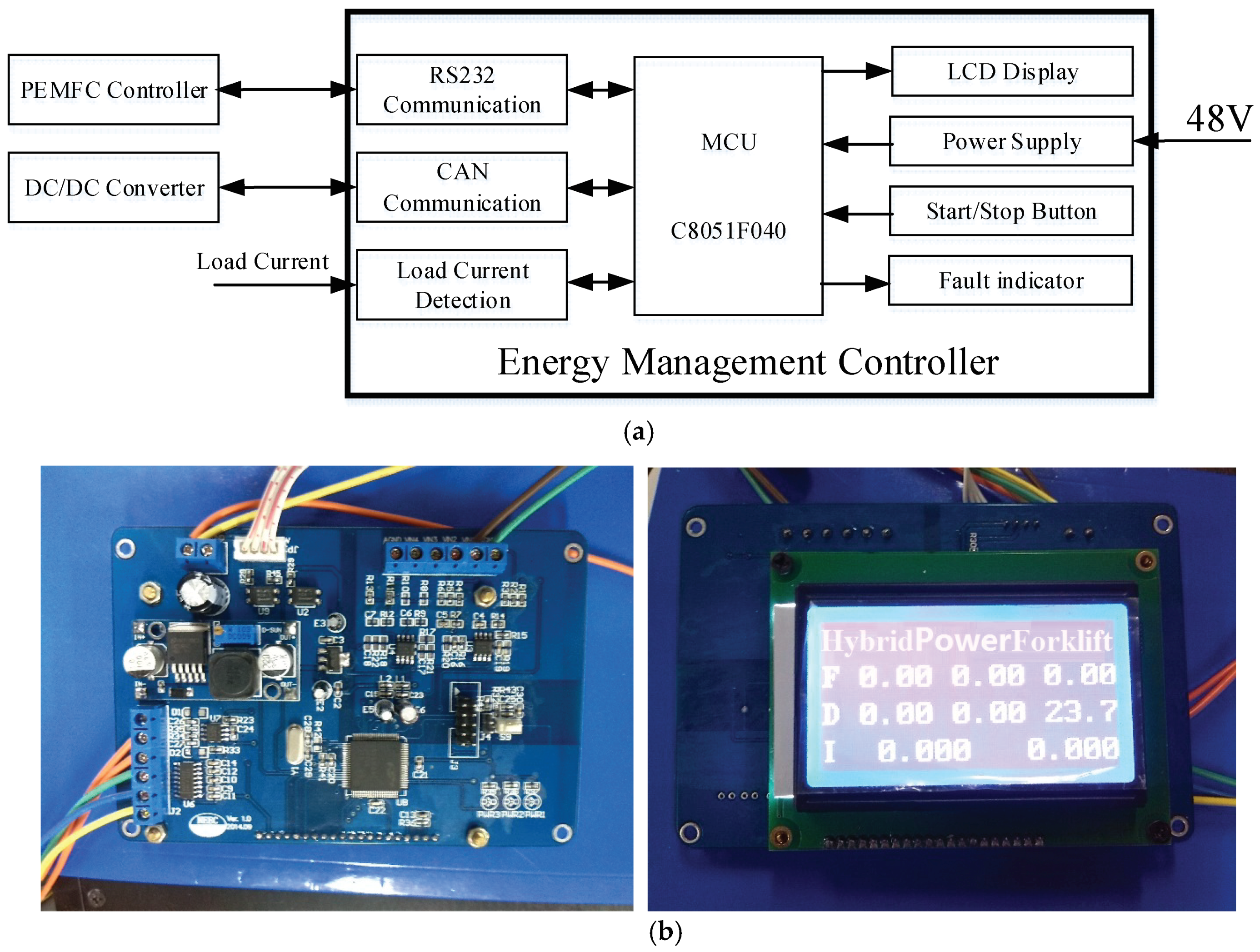
3.6. Energy Management Controller Design

The energy management controller controls the output power of PEMFC on the premise of meeting the demand of load power, making the output current of PEMFC stable, preventing the output current and power mutation when the load mutation occurs, so as to improve the output performance of the PEMFC and prolong the life of the PEMFC. At the same time, the battery is effectively charged and discharged to prevent over-charge and over-discharge of the battery, ensuring stable and safe operation of power sources.
In this study, the energy management controller communicates with the PEMFC controller through the RS232 communication interface to receive the state parameter uploaded by the PEMFC controller, and transmits the control command. It communicates with the DC/DC converter through the CAN communication interface to receive the output voltage, current and other state parameters of the DC/DC converter, and send the DC/DC converter control command. The energy management controller collects the request current of the forklift motor in real-time, estimates the battery SOC online, combines the operating parameters of the PEMFC and DC/DC converter, generates a new control parameter according to the hybrid energy management control strategy, and controls the operation of the PEMFC controller and DC/DC converter. The designed hybrid energy management controller is shown in Figure 9.

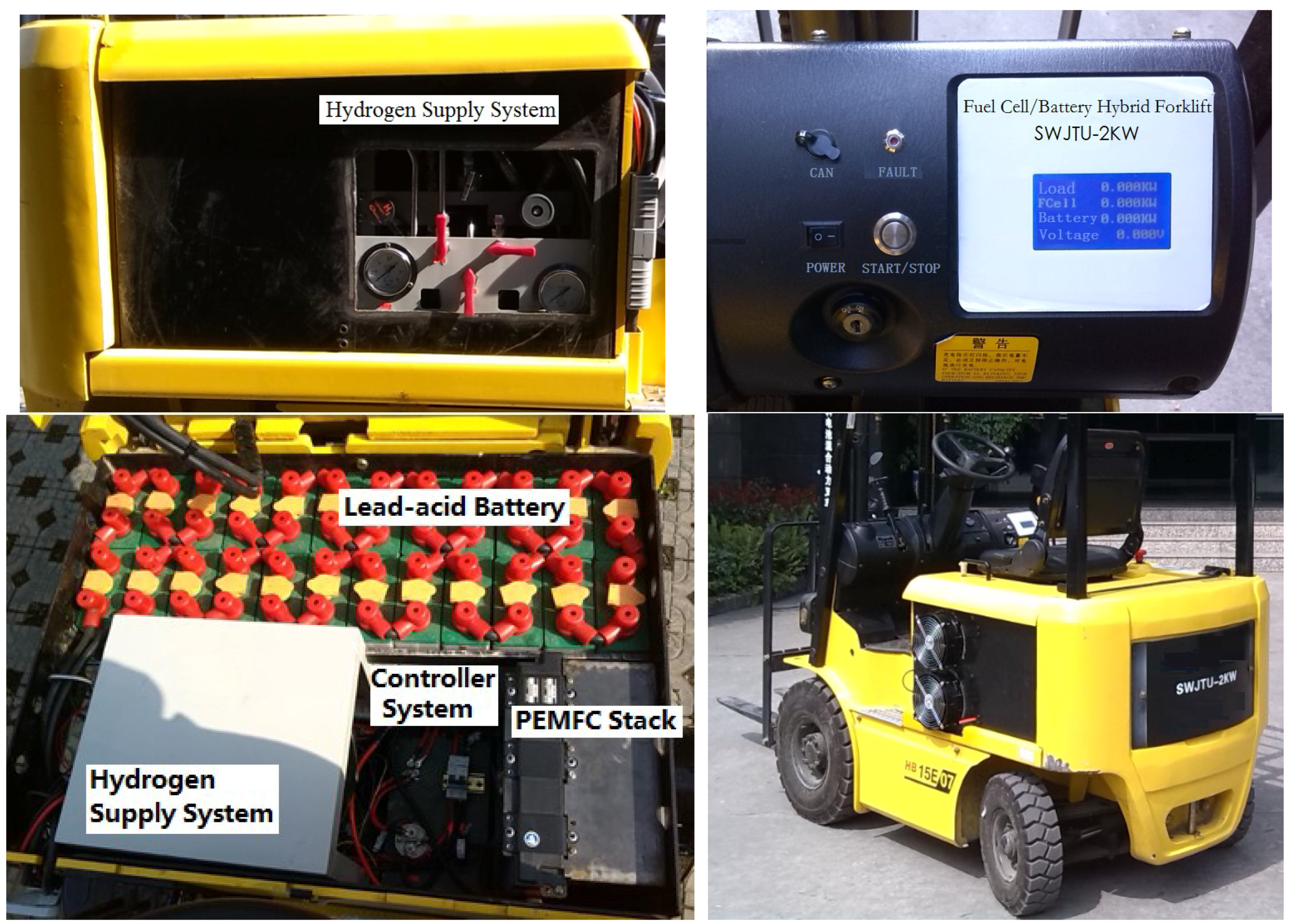
3.7. Hybrid Forklift System

In this study, the fuel cell/battery hybrid forklift system structure consists of the designed PEMFC controller, DC/DC converter, and energy management controller which is shown in Figure 10. The parameters of the hybrid system are shown in Table 2. A fuel cell/battery hybrid forklift prototype is shown in Figure 11. The solenoid valve in the PEMFC stack is connected to the outside of the hybrid power system frame via the pipe to directly discharge the exhaust gas to the atmosphere. “Power Switch” is the power switch of the energy management controller. The “Start/Stop Button” is the start/stop switch for the hybrid power system. The energy management controller issues a control signal according to the state of the start/stop button, and control opened or closed of the relay to implement power supply control of the PEMFC controller.

4. Energy Management Strategy Based on Load Current Following

4.1. Analysis of Characteristics of Hybrid Energy

In this paper, the fuel cell/battery hybrid forklift system includes two power sources: fuel cell and battery. The fuel cell is the main power source and battery is the auxiliary power source.
From the working principle of the fuel cell, the output characteristics of the fuel cell are relatively soft and they cannot respond in a timely manner to the power request of the load when the load power suddenly increases. Thus, it is necessary to gradually increase the power output under the condition that the fuel cells are fully activated, and try to keep the output current of the fuel cells stable during its operation. If the output current of the fuel cell is excessively increased when the load power suddenly increases, the fuel cell terminal voltage will drop, and the fuel cell with too low a terminal voltage will enable the fuel cell to be reverse-polarized, causing irreparable damage. Therefore, when the load power suddenly increases, the fuel cell should not provide a large power output instantaneously. The fuel cell output current should be gradually increased according to the characteristics of the fuel cell, and the output power should be increased until the load power demand is met or the maximum output power is reached.
In the system, the battery is connected in parallel with the DC/DC converter and the forklift motor. Without any independent charging and discharging control unit, the charging and discharging modes are determined by the load power. When the battery needs to access to the output power, it can be connected immediately. When the DC bus voltage is higher than the battery voltage, the battery enters the charging state at once. If the load power suddenly increases, the battery immediately supplements the demanded load power. After the fuel cell gradually increases the output power, the battery will gradually reduce the output power. When the output power of the fuel cell is gradually increased to more than the load power, the battery changes from the discharging state to the charging state, and gets into the charging or floating charging state according to the SOC state.
According to the power of the forklift motor, the operation state of the hybrid power system can be divided into three cases without considering the loss:
(1) Forklift motor is not running (forklift lifting and moving motor systems do not operate).
In this mode, the total load of the hybrid power system is only the battery (the battery can be regarded as the load of the system), and the DC/DC converter can be controlled to charge the battery. At this time, the current and power balance of the hybrid power system are as follows:
{ I Load = 0 I Battery < 0 I Battery = I DC / DC.out P Load = 0 P FC = P Battery < P FC.max
where ILoad is the input current of the motor of forklift (A). IBattery is the battery discharge current of the battery (A), the discharge is the positive, the charge is the negative. IDC/DC.out is the DC/DC converter output current, which is consistent with the variation trend of the output current of the fuel cell (A); PLoad is the motor power of forklift (W); PFC is the output power of the fuel cell (W); PBattery is the discharge power of battery (W); and PFC.max is the maximum output power of the fuel cell.
(2) The required power of forklift motor is less than the maximum output power of the fuel cell.
In this mode, the hybrid power system load includes forklift motor and battery (at this point, the battery can be regarded as the load of the system). The output of the fuel cell provides power to forklift motor on the one hand, and on the other hand, it can be charged according to the SOC of battery. At this time, the current and power balance of the hybrid power system are as follows:
{ I Load < I DC / DC.out I Battery < 0 I Battery = I Load I DC / DC.out P FC = P Battery + P Load < P FC.max
(3) The required power of forklift motor is greater than the maximum output power of the fuel cell.
In this mode, the hybrid system load is only the forklift motor. The fuel cell outputs at the maximum power, and at this point the battery is used as a power source to compensate for the insufficient power output of the fuel cell. At this time, the current and power balance of the hybrid power system are as follows:
{ I Load > I DC / DC.out I Battery > 0 I Battery = I Load I DC / DC.out P Load = P FC + P Battery
For these three cases, we can sum up that there are two cases: battery discharge (IBattery > 0) and charging (IBattery < 0). When the battery is in the discharge state, the energy management controller should gradually increase the output power according to the output characteristics of the fuel cell, reduce the discharge power of the battery, and put the battery in the shallow discharge state, to extend its life. When the battery is in the charge state, the energy management controller should estimate the charging current of the battery according to the SOC of the battery, enable the DC/DC converter to be at a constant current output, and charge the battery to prevent battery overcharging. At the same time, the output current of the fuel cell should be kept stable, so that the fuel cell can work as close to the optimal power point as possible.

4.2. Energy Management Strategy Based on Load Current Following

For a hybrid power system, the energy management strategy will affect the energy utilization efficiency, dynamic response performance, fuel economy, and service life of the hybrid power system [2,13,14,17,24,25,26,27,28]. The main objectives of the energy management strategy for the proposed hybrid forklift is to effectively distribute the output power of each energy unit under the premise of meeting the power demand of the forklift, to reduce the hydrogen fuel consumption, to enhance the fuel utilization rate, to improve the performance of the power supply, to prolong the service life of the fuel cell and the battery, and to increase the cruising range of the forklift. The proposed energy management strategy is about to fulfil the following objectives:
(1)
To enable the DC Bus voltage to stay the allowable voltage range of the forklift motor.
(2)
To prevent battery overcharge and over discharge, to keep the SOC of battery at a reasonable level, and to reserve enough energy for next start-up of the system.
(3)
To keep the fuel cell working at the optimal working point in varying environments, the fuel cell output power optimal, and the fuel utilization efficiency the highest.
(4)
To keep the output current and power of the fuel cell steady, prevent the output from changing with the load power, and to follow the change of load power gradually until the maximum power output is reached.
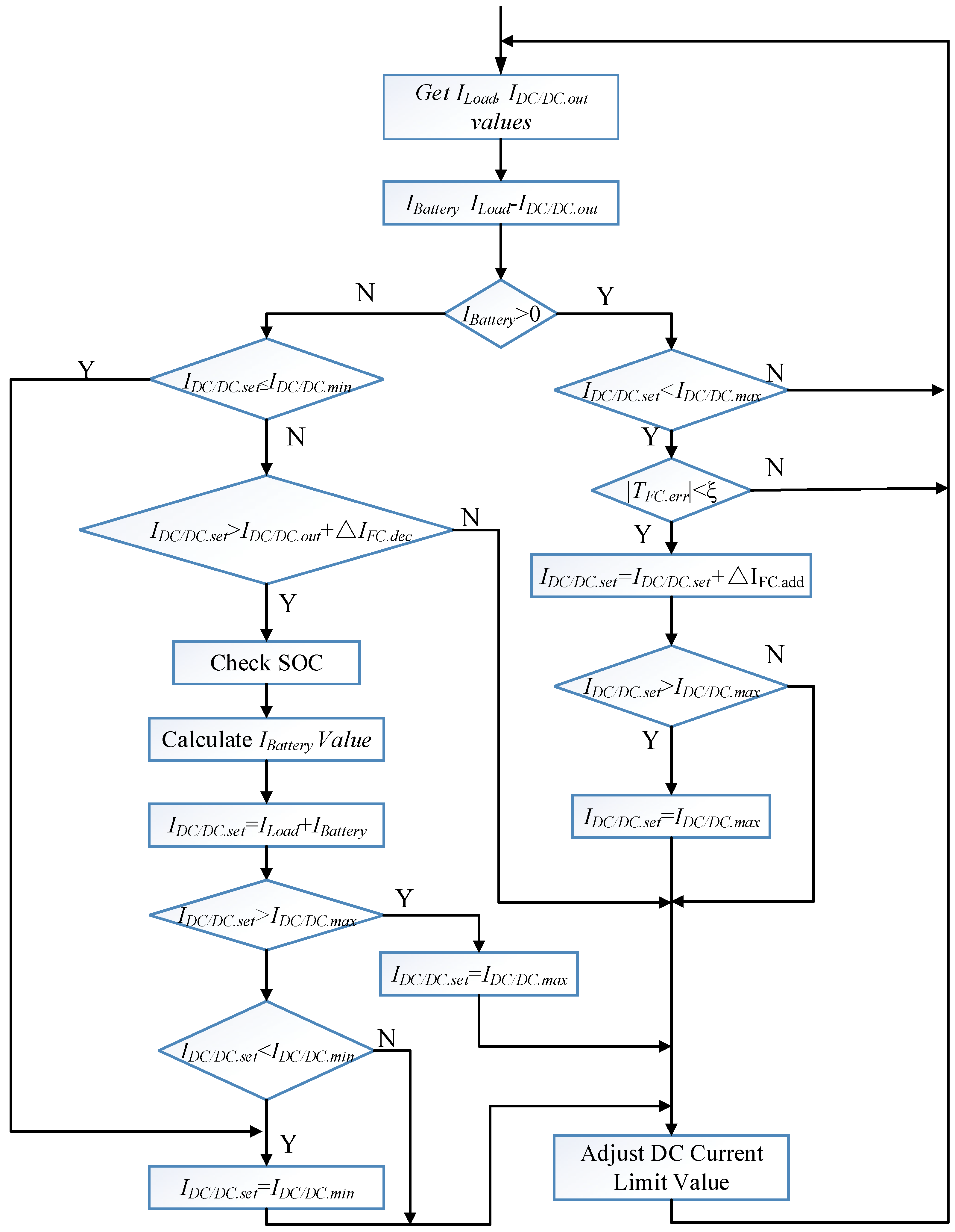
On the grounds of the characteristics of hybrid energy, this paper proposes a hybrid energy management control strategy based on load current following. The control strategy needs to continuously adjust the output current limit of DC/DC converter according to the request current of load, and gradually follow the request current of the load to meet the power demand of forklift. The control flow chart of energy management strategy based on load current following is shown in Figure 12.
IDC/DC.set is the output current setting value of the DC/DC converter (A). IDC/DC.min is the minimum output current value of the DC/DC converter (A), which is converted from the minimum output current of the fuel cell (IFC.min). IDC/DC.max is the maximum output current value of the DC/DC converter (A), which is converted from the maximum output power of the fuel cell (PFC.max).
IFC.add is the adjustment threshold of the fuel cell when output current increasing, it is selected by PEMFC experimental test. When PEMFC operates stably, if the output current of the PEMFC suddenly increases ∆IFC.add, the voltage value of the single cell falls within the allowable range without excessive peak current, then this value can be used as the adjustment value of the current increase. According to the experiment, the value of ∆IFC.add is 3 A in this study.
IFC.dec is the adjustment threshold of the fuel cell when output current reducing, and it is selected by PEMFC experimental test. When IDC/DC.set is large, and IDC/DC.out is small, if the request current of load suddenly increases, the DC/DC converter will enable the output current to be increased immediately, which will cause the immediate increasing of the output current of the fuel cell. If the current increment of the fuel cell is excessive, it will lead to the single cell voltage of the fuel cell is lower than 0.5 V or a large peak current, which will bring about abnormal performance of the fuel cell controller, and then protection or shutdown accidents of the fuel cell power generation system. In this case, the setting value of DC/DC converter should be gradually reduced to avoid excessive increment of the output current of the fuel cell when the request current of load increasing suddenly According to the experiment, the value of ∆IFC.dec is 3 A in this study.
|TFC.err| is the error value of the optimal temperature and the stack temperature of the fuel cell. ξ is the temperature error adjustment threshold, and this value is selected according to the optimal temperature control performance. According to the experiment, the value of |TFC.err| is 3 °C in this study.
After the starting the energy management strategy, the ILoad (request current of the forklift motor) is detected first, and the IBattery (discharge current of the battery) is calculated according to the IDC/DC.out (output current of DC/DC converter), entering the discharge or charge control flow according to the IBattery symbol:
(1)
When IBattery > 0, this indicates that the ILoad is greater than the IDC/DC.out, and the battery is in the discharged state. The energy management control strategy immediately determines whether the IDC/DC.set is the IDC/DC.max If IDC/DC.set is equal to IDC/DC.max, keep the IDC/DC.set unchanged, and the output power of the fuel cell remains unchanged. If IDC/DC.set is less than IDC/DC.set, the |TFC.err| needs to be detected. If |TFC.err| is greater than ξ, it indicates that the fuel cell has not yet reached the optimal output from the previous output state to the current output state, and the stack activation is insufficient (increasing the output current when the stack activation polarization is insufficient, may enable the voltage of the single cell to be reduced to less than 0.5 V, causing the stack to reverse-polarize and damage the stack), the output current of the fuel cell is kept unchanged. If |TFC.err| is less than ξ, it indicates that the stack is fully activated, and the output current of the fuel cell can be increased by ∆IFC.add. Then the energy management control strategy modifies the IDC/DC.set to increase the fuel cell output current ∆IFC.add (when the adjusted value exceeds the maximum output value of the fuel cell, the IDC/DC.set is equal to the maximum output value of the fuel cell). This adjustment is repeated to enable the output current of the fuel cell to follow the request current of the forklift motor gradually, until the output current of the fuel cell reaches a maximum value.
(2)
When IBattery < 0, this indicates that the ILoad is less than the IDC/DC.out, and the battery is in the charging state. The energy management control strategy immediately determines whether the IDC/DC.set is the IDC/DC.min. If IDC/DC.set is equal to IDC/DC.min, keep the IDC/DC.set unchanged, and the output power of the fuel cell remains unchanged. In order to prevent the sudden increase of ILoad causing the output current of the fuel cell to immediately increase to the IDC/DC.set, and the single cell voltage of the fuel cell is too low or a large peak current occurs affects the normal operation of the PEMFC controller, it is necessary to judge whether the difference between the IDC/DC.set and ILoad is greater than the reduction adjustment threshold ∆IFC.dec, if IDC/DC.set is greater than IDC/DC.min. If the difference is greater than the adjustment threshold ∆IFC.dec, the energy management controller recalculates the SOC of battery, and selects an appropriate charging current IBattery according to the current SOC of battery, and takes the sum of IBattery and ILoad as the new setting value of IDC/DC.set. With the increase of the SOC, the charging current of the battery will gradually decrease.

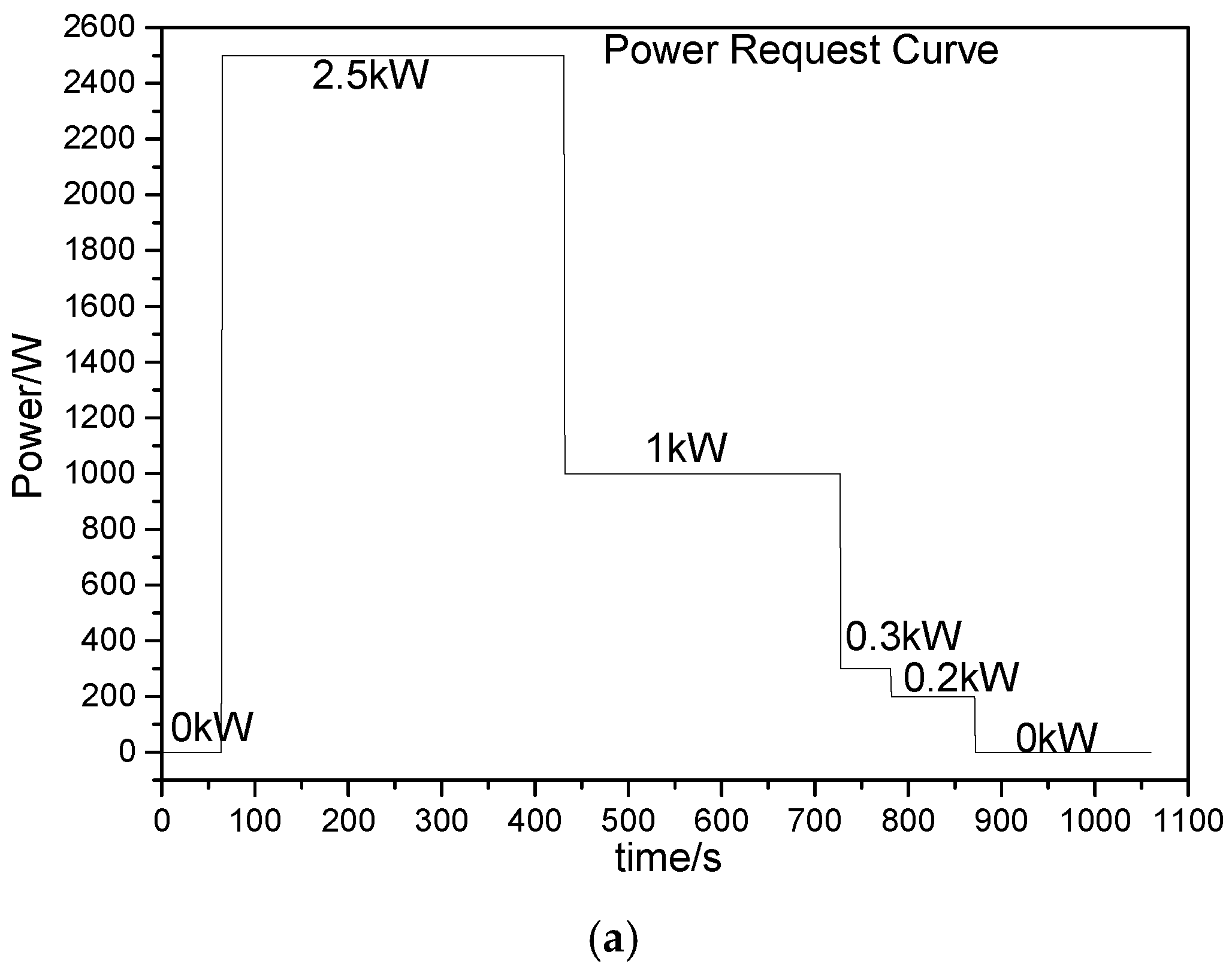
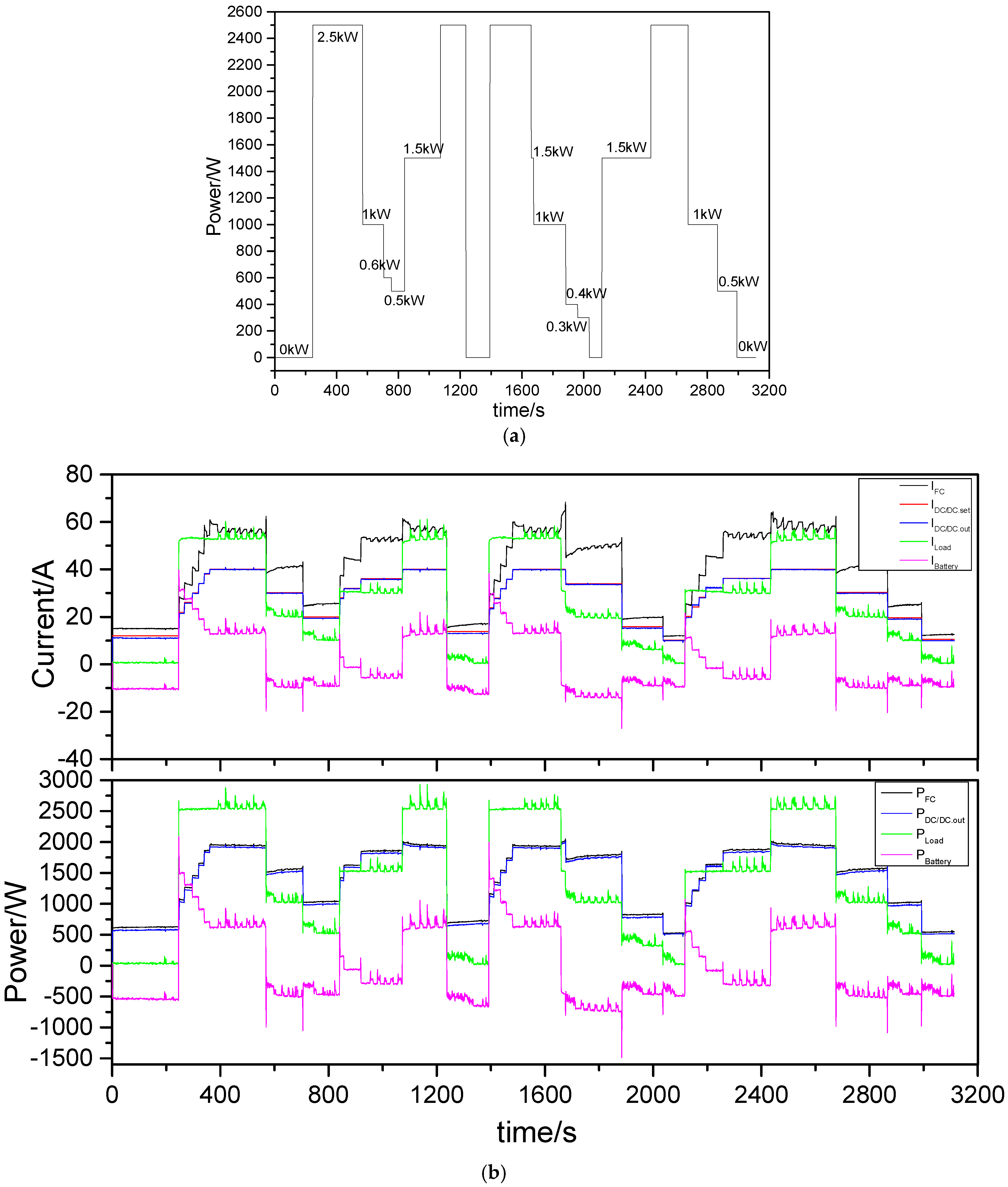
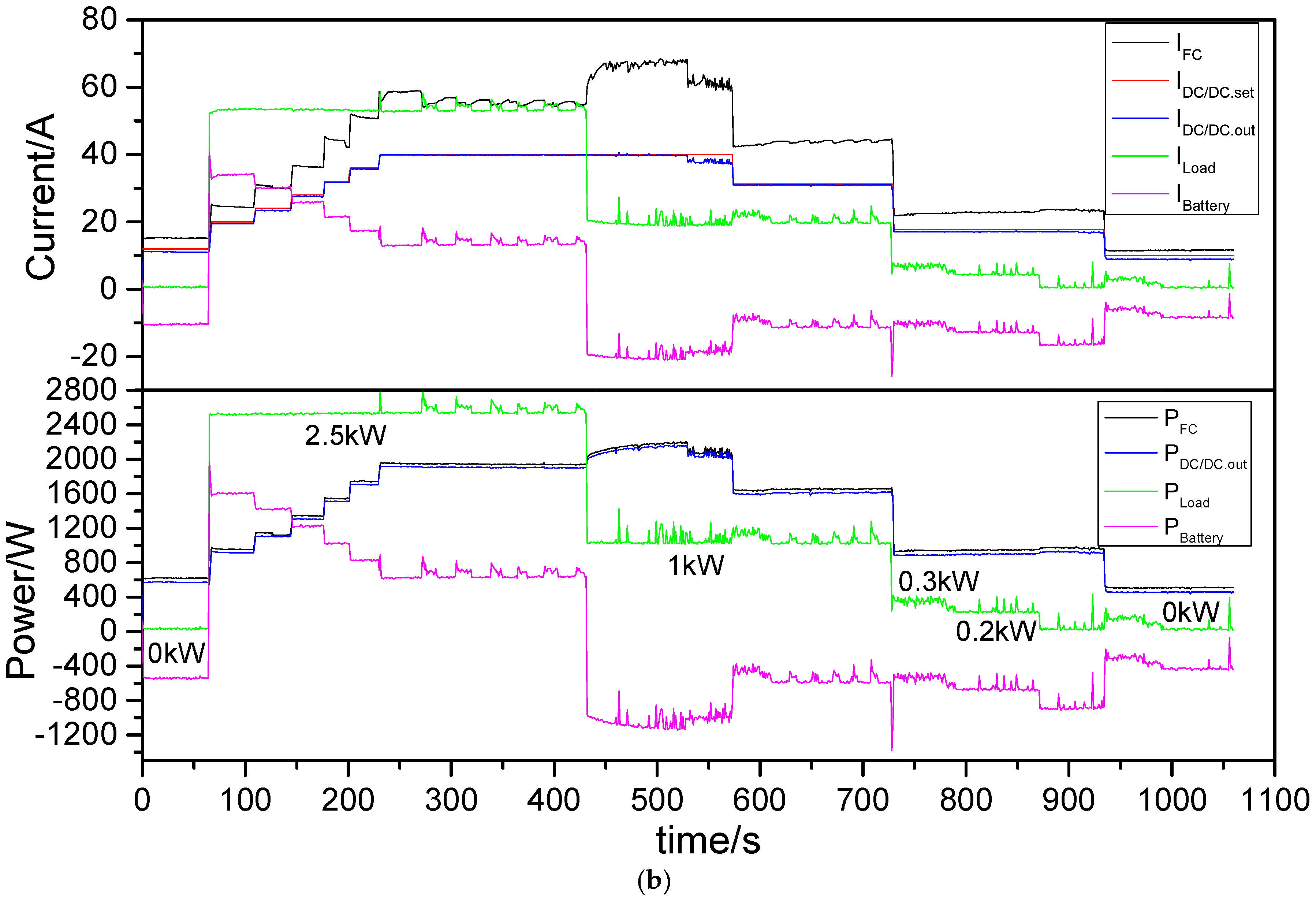
4.3. Test of Energy Management Strategy

In this paper, the 2.6 kW electronic load is used instead of the forklift motor in Figure 10 to build a fuel cell/battery hybrid simulation test system, which tests the proposed hybrid energy management strategy to verify its effectiveness. During the test, the energy management controller obtains the output parameters of each energy source of the hybrid system through the CAN communication interface, and draws a response curve of current and power.
(1) Response test when load power is slowly reduced.
The electronic load is used to simulate the power request of load shown in Figure 13a, and the hybrid power system is controlled by the proposed load current following control strategy. The response curve is shown in Figure 13b.
① According to the proposed energy management strategy, when the request power of load is 0 kW, the IFC is equal to IFC.min, the output current of the fuel cell is stable, and the battery is charged.
② At the moment when the load power suddenly increases to 2.5 kW, according to the current activation situation of the stack, the proposed energy management control strategy gradually increases the output current and power of the fuel cell, and maintains the output current and power output smoothly in each adjustment phase. During the adjustment process, the insufficiently part of the load request power is compensated by the battery.
③ When the PFC reaches the maximum rated power, the proposed energy management control strategy controls the fuel cell output at the maximum rated power, and the insufficiently part of the load request power is compensated by the battery.
④ When the PLoad is suddenly reduced from 2.5 kW to 1 kW, since the PLoad is less than PFC, the battery is switched from the discharged state to the charged state. The energy management control strategy estimates the SOC value of battery and IBattery, and determines the output current limit of the DC/DC converter. Due to the discharge of the previous battery, the SOC is low, the estimated charging current is large and the calculated setting current value of IDC/DC.set is greater than the maximum current limit value of the DC/DC converter, the setting value of IDC/DC.set is kept unchanged.
⑤ As IBattery decreases, when the difference between IDC/DC.set and IDC/DC.out reaches the adjustment threshold ∆IFC.dec, the energy management control strategy re-estimates the output setting value and adjusts the output current limit value. When it satisfies the load power, at the same time, the battery can be continuously charged with a new charging current.
⑥ When the load continues to reduce power, the energy management control strategy immediately estimates the SOC of battery, calculates a new output setting value of IDC/DC.set, and always keeps the battery in the constant current charging mode, keeping the output current and output power of the fuel cell stable while meeting the power demand of load.
The current and power response curves shown in Figure 12 indicate that the proposed energy management control strategy has achieved the control objectives. During the entire operation, the output current of the fuel cell is stable, and the output power of the fuel cell gradually follows the load power request, preventing the impact of load abrupt changes on the fuel cell.
(2) Response test when the load power is frequently changing.
The electronic load is used to simulate the power request of load shown in Figure 14a, and the hybrid power system is controlled by the proposed load current following control strategy. The response curve is shown in Figure 14b.
① According to the proposed energy management strategy, when the request power of load is 0 kW, the IFC is equal to IFC.min, the output current of the fuel cell is stable, and the battery is charged.
② At the moment when the load power suddenly increases, according to the activation situation of the stack, the proposed energy management control strategy gradually increases the output of the fuel cell, and maintains the output current and power output smoothly in each adjustment phase. During the adjustment process, the insufficient part of the load request power is compensated by the battery.
③ When the PFC reaches the maximum rated power, the proposed energy management control strategy controls the fuel cell output at the maximum rated power, and the insufficient part of the load request power is compensated by the battery.
④ When the load power drops suddenly, the energy management control strategy immediately follows the load request current, adjusts the output setting value of the DC/DC converter, and makes the constant current output of the DC/DC converter ensure the output current of the fuel cell is stable.
The current and power response curves shown in Figure 13 indicate that the proposed energy management control strategy has achieved the control objectives. During the entire operation, the output of the fuel cell is stable, meets the output characteristics of the fuel cell, and the control strategy is practical and effective.

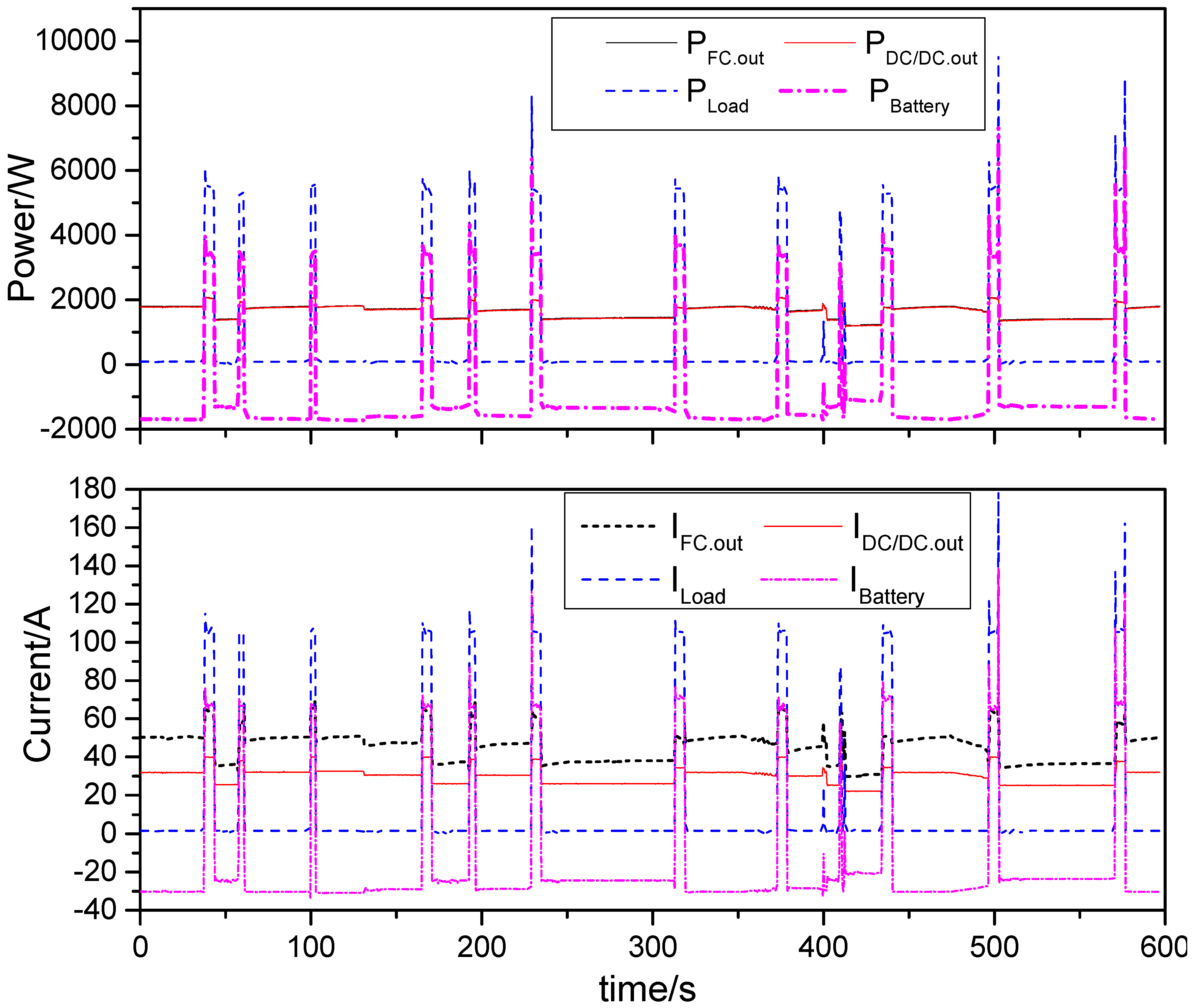
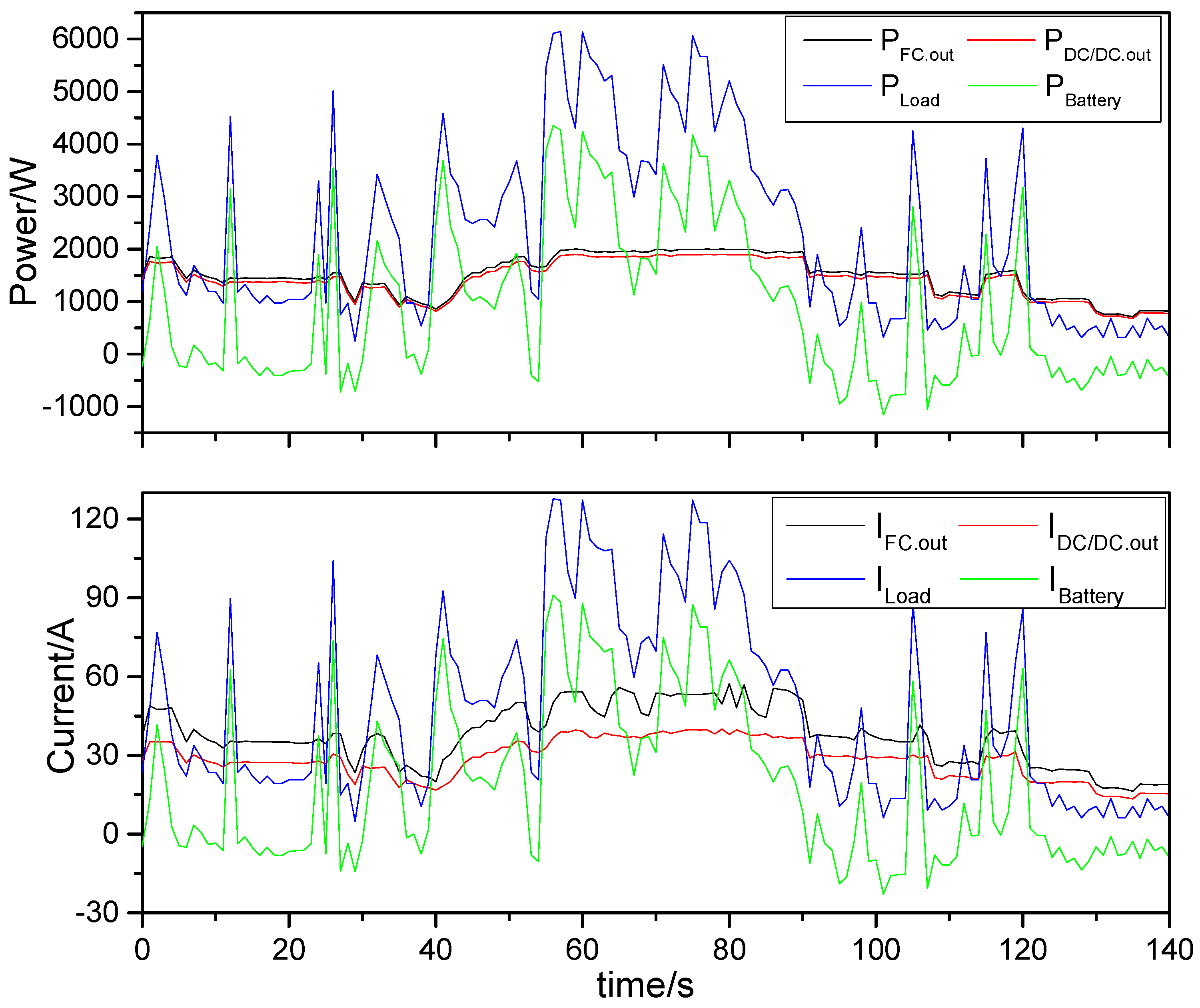
5. Test and Result of Hybrid Forklift

In this paper, the energy management controller is realized by using the proposed energy management control strategy, and the fuel cell/battery hybrid forklift prototype is constructed by using the PEMFC controller, DC/DC converter, and energy management controller. In order to verify the effectiveness and control performance of the energy management strategy and fuel cell/battery hybrid forklift, an experimental test was carried out on the lifting and moving of the fuel cell/battery hybrid forklift prototype.
(1) Lifting test of the hybrid forklift.
When the fuel cell/battery hybrid forklift lifts the cargo, the response curves of power and current of the fuel cell and battery are shown in Figure 15.
Before the lifting motor is operated, the fuel cell charges the battery and its output power is less than 2 kW. When the cargo is lifted, the power of load suddenly increases, and the fuel cell gradually increases the output power under the control of the energy management controller until the rated power of 2 kW is reached, and the insufficient power of load is supplemented by the battery. In the course of lifting, the output current and power of the fuel cell are gradually increased, and the output is generally stable, which conforms to the output characteristics of the fuel cell. When the cargo lifting is completed, the request power of load is instantaneously reduced to 0 kW. Under the control of the energy management controller, the output power of the fuel cell is gradually reduced, and the output current of the fuel cell is gradually reduced to the charging current value of the battery. During the whole operation process, the output current of the fuel cell is stable, and the output power changes slowly, which is consistent with the output characteristics of the fuel cell. The battery is charged and discharged according to the power of the load. The test results show that the fuel cell/battery hybrid forklift prototype meets the load condition demand while lifting the cargo. The energy distribution of each power unit is reasonable and the control effect is good.
(2) Moving test of hybrid forklift.
The fuel cell/battery hybrid forklift is tested under actual moving conditions. The power and current response curves of the fuel cell and battery are shown in Figure 16.
In the process of moving, the energy management controller reasonably distributes the output of each power source. On the premise of ensuring the power demand of load, the output power of the fuel cell gradually increases or decreases with the power of load, and the output is stable. When the power demand of load is lower than the output power of the fuel cell, the battery enters the charging state, otherwise the battery enters the discharging state. The output current of the fuel cell gradually increases or decreases with the current of load, and the change process is slow and stable, which meets the requirement of the output characteristic of the fuel cell. The test results show that the performance of the fuel cell/battery hybrid forklift is good, the functional units of the hybrid power system operate normally, the energy distribution is reasonable and the energy management strategy is effective.

6. Conclusions

In this paper, a fuel cell/battery hybrid forklift is designed based on combined characteristics of lead-acid batteries and fuel cells to reduce the size and configuration power of the fuel cell, to improve the dynamic response performance of the fuel cell, and to extend the cruising range of the battery. According to the selected topology of the hybrid power system, the hardware units, such as the PEMFC controller, unidirectional buck-boost DC/DC converter, and energy management controller, are designed in detail, and a fuel cell/battery hybrid forklift prototype is built. An energy management strategy based on load current following is proposed to manage the fuel cell/battery hybrid energy. Under the premise of meeting the power demand of the forklift, the output current and power of the fuel cell are stable, the output performance is optimal, and the SOC of the battery is maintained at a reasonable level. The proposed energy management strategy is tested by using an electronic load to simulate different power requests of the load. The test results show that the proposed energy management strategy achieves the energy management control target, the output meets the output characteristics requirements of the fuel cell, the output is stable, and the request current of the load can be followed during operation to gradually adjust the output current of the fuel cell. The hybrid forklift prototype was tested for moving and lifting. The test results verify the proposed control strategy, the energy distribution, and the running performance of the system.

Author Contributions

Conceptualization: Z.Y. and Y.H.; resources: Z.Y. and F.Z.; validation: Z.Y. and L.W.; writing—original draft: Z.Y., L.W., and Y.H.; writing—review and editing: Z.Y. and F.Z.

Funding

This work was supported by the Fundamental Research Funds for the Central Universities (2016NZYQN12) and the open research subject of the Key Laboratory of Sichuan signal and information processing, Xihua University (SZJJ2016-094).

Conflicts of Interest

The authors declare no conflict of interest. It should be noted that the whole work was accomplished by the authors collaboratively. All authors read and approved the final manuscript.

References

  1. Jensen, H.B.; Schaltz, E.; Koustrup, P.S.; Andreasen, S.J.; Kaer, S.K. Evaluation of fuel-cell range extender impact on hybrid electrical vehicle performance. IEEE Trans. Veh. Technol. 2013, 62, 50–60. [Google Scholar] [CrossRef]
  2. Lachhab, I.; Krichen, L. An improved energy management strategy for FC/UC hybrid electric vehicles propelled by motor-wheels. Int. J. Hydrog. Energy 2014, 39, 571–581. [Google Scholar] [CrossRef]
  3. Lototskyy, M.V.; Tolj, I.; Parsons, A.; Smith, F.; Sita, C.; Linkov, V. Performance of electric forklift with low-temperature polymer exchange membrane fuel cell power module and metal hydride hydrogen storage extension tank. J. Power Sour. 2016, 316, 239–250. [Google Scholar] [CrossRef]
  4. Garche, J.; Jörissen, L. Applications of fuel cell technology: Status and perspectives. Electrochem. Soc. Interface 2015, 24, 39–43. [Google Scholar] [CrossRef]
  5. Sharaf, O.Z.; Orhan, M.F. An overview of fuel cell technology: Fundamentals and applications. Renew. Sustain. Energy Rev. 2014, 32, 810–853. [Google Scholar] [CrossRef]
  6. Das, V.; Padmanaban, S.; Venkitusamy, K.; Selvamuthukumaran, R.; Blaabjerg, F.; Siano, P. Recent advances and challenges of fuel cell based power system architectures and control–A review. Renew. Sustain. Energy Rev. 2017, 73, 10–18. [Google Scholar] [CrossRef]
  7. Kunusch, C.; Puleston, P.; Mayosky, M. PEM Fuel Cell Systems. In Sliding-Mode Control of PEM Fuel Cells. Advances in Industrial Control; Springer: London, UK, 2012. [Google Scholar]
  8. Comparison of Fuel Cell Technologies. U.S. Department of Energy, Energy Efficiency and Fuel Cell Technologies Program. February 2011. Available online: https://www1.eere.energy.gov/hydrogenandfuelcells/fuelcells/pdfs/fc_comparison_chart.pdf (accessed on 4 August 2011).
  9. Hsieh, C.-Y.; Nguyen, X.-V.; Weng, F.-B.; Kuo, T.-W.; Lee, C.-Y.; Su, A. Developing Hybrid–Power Fuel Cells with a Low–Pressure Hydrogen–Storage System used in an Electric Forklifts. Int. J. Electrochem. Sci. 2017, 12, 6266–6281. [Google Scholar] [CrossRef]
  10. Keränen, T.M.; Karimäki, H.; Viitakangas, J.; Vallet, J.; Ihonen, J.; Hyötylä, P.; Uusalo, H.; Tingelöf, T. Development of integrated fuel cell hybrid power source for electric forklift. J. Power Sour. 2011, 196, 9058–9068. [Google Scholar] [CrossRef]
  11. Houf, W.G.; Evans, G.H.; Ekoto, I.W.; Merilo, E.G.; Groethe, M.A. Hydrogen fuel-cell forklift vehicle releases in enclosed spaces. Int. J. Hydrog. Energy 2013, 38, 8179–8189. [Google Scholar] [CrossRef]
  12. Lototskyy, M.V.; Tolj, I.; Davids, M.W.; Klochko, Y.V.; Parsons, A.; Swanepoel, D.; Ehlers, R.; Louw, G.; van der Westhuizen, B.; Smith, F. Metal hydride hydrogen storage and supply systems for electric forklift with low-temperature proton exchange membrane fuel cell power module. Int. J. Hydrog. Energy 2016, 41, 13831–13842. [Google Scholar] [CrossRef]
  13. Sabri, M.F.M.; Danapalasingam, K.A.; Rahmat, M.F. A review on hybrid electric vehicles architecture and energy management strategies. Renew. Sustain. Energy Rev. 2016, 53, 1433–1442. [Google Scholar] [CrossRef]
  14. Sulaiman, N.; Hannan, M.A.; Mohamed, A.; Majlan, E.H.; Daud, W.W. A review on energy management system for fuel cell hybrid electric vehicle: Issues and challenges. Renew. Sustain. Energy Rev. 2015, 52, 802–814. [Google Scholar] [CrossRef]
  15. Wu, B.; Parkes, M.A.; Yufit, V.; De Benedetti, L.; Veismann, S.; Wirsching, C.; Vesper, F.; Martinez-Botas, R.F.; Marquis, A.J.; Offer, G.J. Design and testing of a 9.5 kWe proton exchange membrane fuel cell–supercapacitor passive hybrid system. Int. J. Hydrog. Energy 2014, 39, 7885–7896. [Google Scholar] [CrossRef]
  16. Shin, M.-H.; Eom, T.-H.; Park, Y.-H.; Won, C.-Y. Design and control of fuel cell-battery hybrid system for forklift. In Proceedings of the 2016 IEEE Conference and Expo Transportation Electrification Asia-Pacific (ITEC Asia-Pacific), Busan, Korea, 1–4 June 2016; pp. 584–589. [Google Scholar]
  17. Han, Y.; Chen, W.; Li, Q. Energy management strategy based on multiple operating states for a photovoltaic/fuel cell/energy storage DC microgrid. Energies 2017, 10, 136. [Google Scholar] [CrossRef]
  18. Hong, Z.; Li, Q.; Han, Y.; Shang, W.; Zhu, Y.; Chen, W. An energy management strategy based on dynamic power factor for fuel cell/battery hybrid locomotive. Int. J. Hydrog. Energy 2018, 43, 3261–3272. [Google Scholar] [CrossRef]
  19. Jia, J.; Li, Q.; Wang, Y.; Cham, Y.T.; Han, M. Modeling and dynamic characteristic simulation of a proton exchange membrane fuel cell. IEEE Trans. Energy Convers. 2009, 24, 283–291. [Google Scholar] [CrossRef]
  20. Li, Q.; Chen, W.; Liu, S.; Gao, Z.; Yang, S. Temperature optimization and control of optimal performance for a 300 W open cathode proton exchange membrane fuel cell. Procedia Eng. 2012, 29, 179–183. [Google Scholar] [CrossRef]
  21. Wei, D.; Zheng, D.; Chu, L. Output control of optimal performance for air-cooling PEMFC stack. CIESC J. 2010, 5, 1293–1300. [Google Scholar]
  22. You, Z.; Xu, T.; Liu, Z.; Peng, Y.; Cheng, W. Study on air-cooled self-humidifying PEMFC control method based on segmented predict negative feedback control. Electrochim. Acta 2014, 132, 389–396. [Google Scholar]
  23. Zhi, Y.; Tao, L.; Qing, S.; Qi, L. Design of Generation Controller of Air-Cooled Self-Humidifying Proton Exchange Membrane Fuel Cell. Trans. China Electrotech. Soc. 2018, 33, 442–450. [Google Scholar]
  24. Xu, L.; Ouyang, M.; Li, J.; Yang, F.; Lu, L.; Hua, J. Application of Pontryagin’s Minimal Principle to the energy management strategy of plugin fuel cell electric vehicles. Int. J. Hydrog. Energy 2013, 38, 10104–10115. [Google Scholar] [CrossRef]
  25. Carignano, M.G.; Costa-Castelló, R.; Roda, V.; Nigro, N.M.; Junco, S.; Feroldi, D. Energy management strategy for fuel cell-supercapacitor hybrid vehicles based on prediction of energy demand. J. Power Sour. 2017, 360, 419–433. [Google Scholar] [CrossRef]
  26. Ahmadi, S.; Bathaee, S.M.T.; Hosseinpour, A.H. Improving fuel economy and performance of a fuel-cell hybrid electric vehicle (fuel-cell, battery, and ultra-capacitor) using optimized energy management strategy. Energy Convers. Manag. 2018, 160, 74–84. [Google Scholar] [CrossRef]
  27. Zhang, W.; Li, J.; Xu, L.; Ouyang, M. Optimization for a fuel cell/battery/capacity tram with equivalent consumption minimization strategy. Energy Convers. Manag. 2017, 134, 59–69. [Google Scholar] [CrossRef]
  28. Ettihir, K.; Boulon, L.; Agbossou, K. Optimization-based energy management strategy for a fuel cell/battery hybrid power system. Appl. Energy 2016, 163, 142–153. [Google Scholar] [CrossRef]
Figure 1. Topology of the fuel cell/battery hybrid power system. (a) Simple topology of the hybrid power system; (b) topology of the hybrid power system with an unidirectional DC/DC converter; (c) topology of hybrid power system with a bidirectional DC/DC converter; and (d) the topology of the hybrid power system with unidirectional and bidirectional DC/DC converters.
Energies 11 03440 g001
Figure 2. Fuel cell/battery hybrid power system.
Energies 11 03440 g002
Figure 3. Hydrogen supply system.
Energies 11 03440 g003
Figure 4. Diagram of the air-cooled PEMFC system.
Energies 11 03440 g004
Figure 5. Functional diagram and control flowchart of the PEMFC controller. (a) Functional diagram of the PEMFC controller; (b) Control flowchart of the PEMFC controller.
Energies 11 03440 g005aEnergies 11 03440 g005b
Figure 6. PEMFC controller. (a) Prototype of the PEMFC controller; (b) Response curve of control.
Energies 11 03440 g006
Figure 7. Functional diagram of the DC/DC converter. (a) Parallel block diagram of the NiQor module. (b) Control board functional diagram of the DC/DC converter.
Energies 11 03440 g007aEnergies 11 03440 g007b
Figure 8. Unidirectional buck-boost DC/DC converter. (a) Prototype of the DC/DC converter. (b) Program control and response test. (c) Efficiency test.
Energies 11 03440 g008aEnergies 11 03440 g008b
Figure 9. Energy management controller. (a) Functional diagram of the energy management controller; (b) Prototype of the energy management controller.
Energies 11 03440 g009
Figure 10. Fuel cell/battery hybrid forklift system structure.
Energies 11 03440 g010
Figure 11. Prototype fuel cell/battery hybrid forklift.
Energies 11 03440 g011
Figure 12. Control flow chart of energy management strategy.
Energies 11 03440 g012
Figure 13. Response test when load power is slowly reduced. (a) Request curve of load power; and (b) the response curve of current and power.
Energies 11 03440 g013aEnergies 11 03440 g013b
Figure 14. Response test when the load power is frequent change. (a) Request curve of load power; and (b) the response curve of current and power.
Energies 11 03440 g014
Figure 15. Response curve of the hybrid forklift while lifting.
Energies 11 03440 g015
Figure 16. Response curve of moving the hybrid forklift.
Energies 11 03440 g016
Table 1. Relationship of the charging current and SOC.
SOCSOC < 60%60% < SOC < 80%80% < SOC < 90%SOC > 90%
Charging current0.3 C (30 A)0.2 C (20 A)0.07 C (7 A)Floating charge
Table 2. Parameters of the hybrid system.
SubsystemsDescriptionsValues
Fuel Cell
(PEMFC)
Rated power2000 W
Cells56 pieces
Voltage range30–56 V
Maximum current75 A
Maximum temperature75 °C
Lead-acid BatteryRated voltage48 V
Rated capacity100 Ah
Set numbers24 series
ForkliftMoving motorRated voltage48 V
Rated power6300 W
Lifting motorRated voltage48 V
Rated power8600 W

