Integrated Optimal Dispatch of a Rural Micro-Energy-Grid with Multi-Energy Stream Based on Model Predictive Control

Abstract
:1. Introduction
- (1)
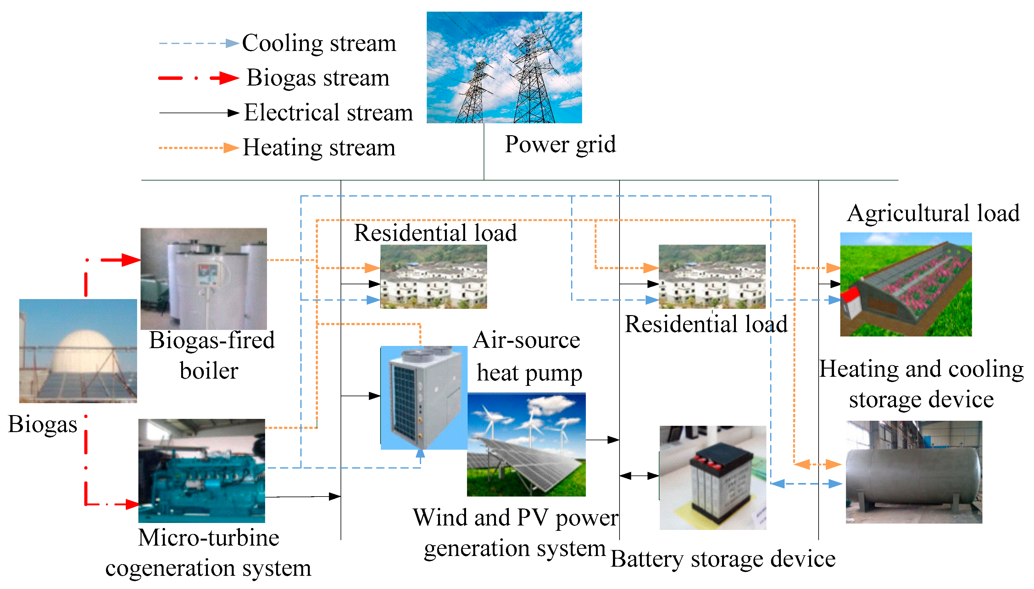
- The energy-supply architecture of the micro-energy-grid, including wind, PV, micro-turbine, and other micro-sources, is built, and the demand of cooling-heating-electricity load is considered.
- (2)
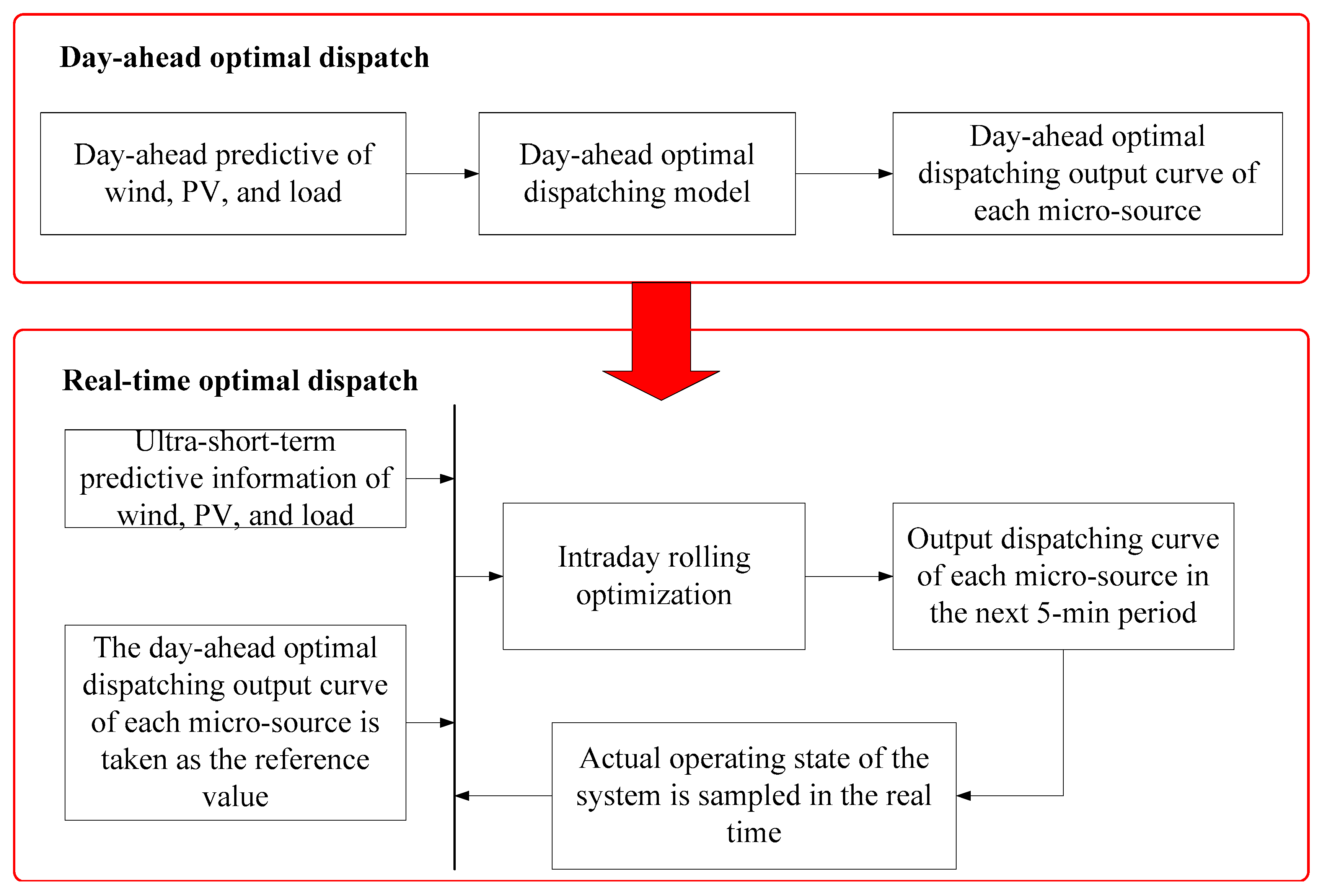
- An integrated optimal dispatching method based on model predictive control for the micro-energy-grid, which divides the optimal dispatching process into the day-ahead optimal dispatch and the real-time optimal dispatch, is proposed. In the day-ahead optimal dispatch, the optimal dispatch model of the micro-energy-grid is built taking the daily minimum operating cost as the objective function, and the hourly optimal output curve of each micro-source in the next day is obtained. In the real-time optimal dispatch, based on the model predictive control theory, taking the day-ahead optimal dispatching results as the reference values, intraday multi-period rolling optimization and sampling real-time system state for feedback correction are conducted.
- (3)
- In this study, the energy-supply architecture of the proposed energy grid is suitable for the rural areas of China. Biogas, PV energy and other biomass and renewable energy sources are used to achieve the integrated utilization of all kinds of resources in rural areas.
2. Components and Energy-Supply Mechanism of Rural Micro-Energy-Grid
3. Integrated Optimal Dispatching Framework of the Micro-Energy-Grid Based on Model Predictive Control
4. Integrated Optimal Dispatching Model of the Rural Micro-Energy-Grid
4.1. Day-Ahead Optimal Dispatching Model
- (1)
- Electrical power balance constraint condition:
- (2)
- Heating power balance constraint condition:
- (3)
- Cooling power balance constraint condition:
- (4)
- Micro-turbine constraint conditions:
- (5)
- Heat-recovery boiler constraint conditions:
- (6)
- Biogas-fired boiler constraint conditions:
- (7)
- Lithium-bromide absorption-type refrigerator constraint conditions:
- (8)
- Cooling-heating-electricity storage device constraint conditions:Because the functions and principles of the battery storage device and the cooling and heating storage device are similar, their general models are as follows:
- (9)
- Air-source heat pump constraint conditions:
- (10)
- Power exchange between the micro-energy-grid and the distribution network constraint condition:
- (11)
- Reserve power constraint condition:
4.2 Real-Time Optimal Dispatching Model
4.2.1. Predictive Model
4.2.2. Objective Function (Rolling Optimization)
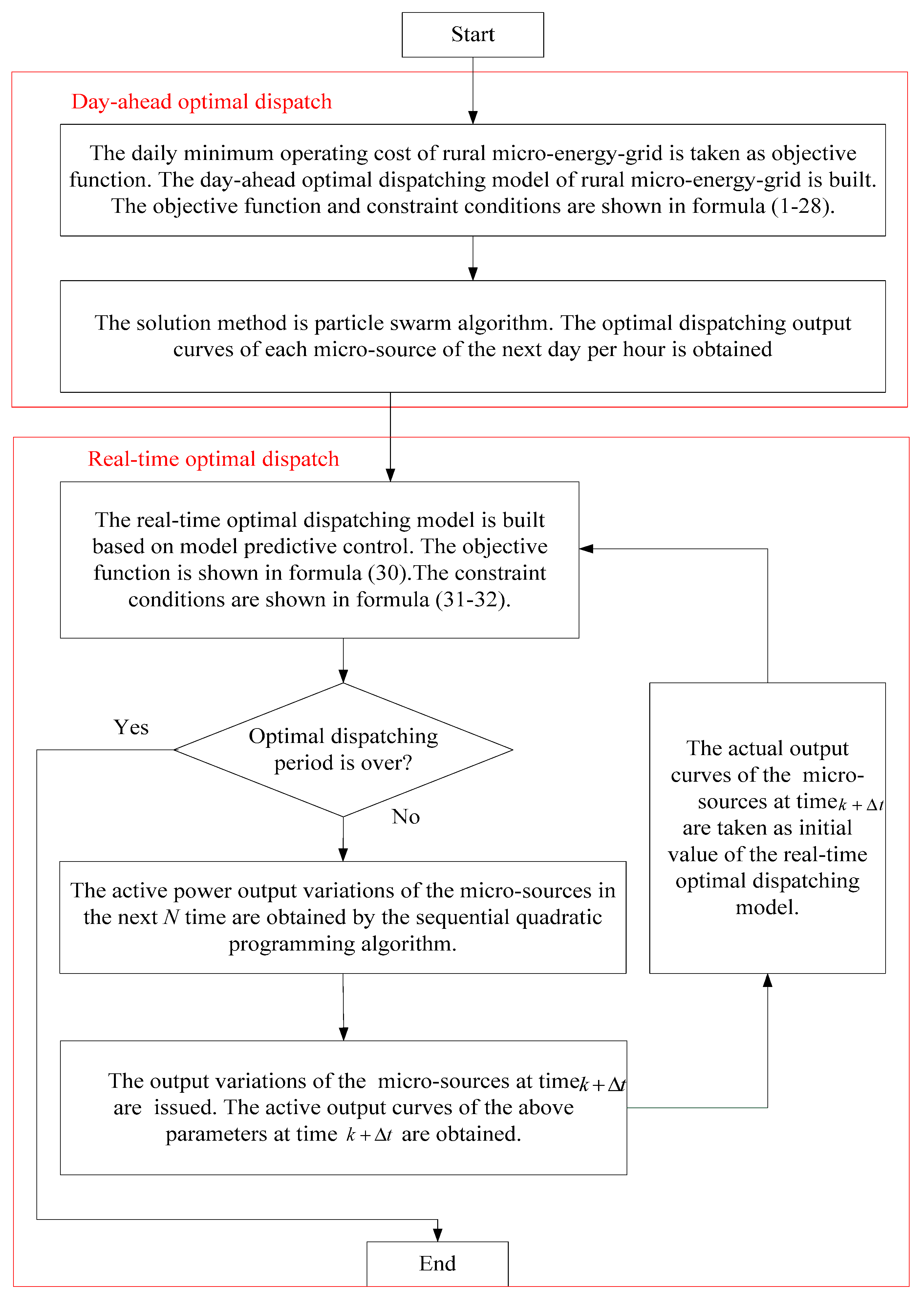
4.3. Integrated Optimal Dispatching Model Solution
- (1)
- The daily minimum operating cost of the rural micro-energy-grid is taken as the objective function, and the day-ahead optimal dispatching model of the rural micro-energy-grid is built. The problem is solved using the particle swarm algorithm, and the hourly optimal dispatching output curves in the next day are obtained for each micro-source.
- (2)
- The power output curves of the micro-sources in the day-ahead optimal dispatch are taken as the reference values. The real-time optimal dispatching model is built based on model predictive control. The active power output variations of the micro-sources in the next N time are obtained by the sequential quadratic programming algorithm.
- (3)
- The power output variations of the micro-sources at time are issued, and the active power output curves of the micro-sources at time are obtained.
- (4)
- The actual power output curves of the micro-sources at time are taken as the initial values of the real-time optimal dispatching model. The process then returns to Step 2, and a new round of optimization is performed.
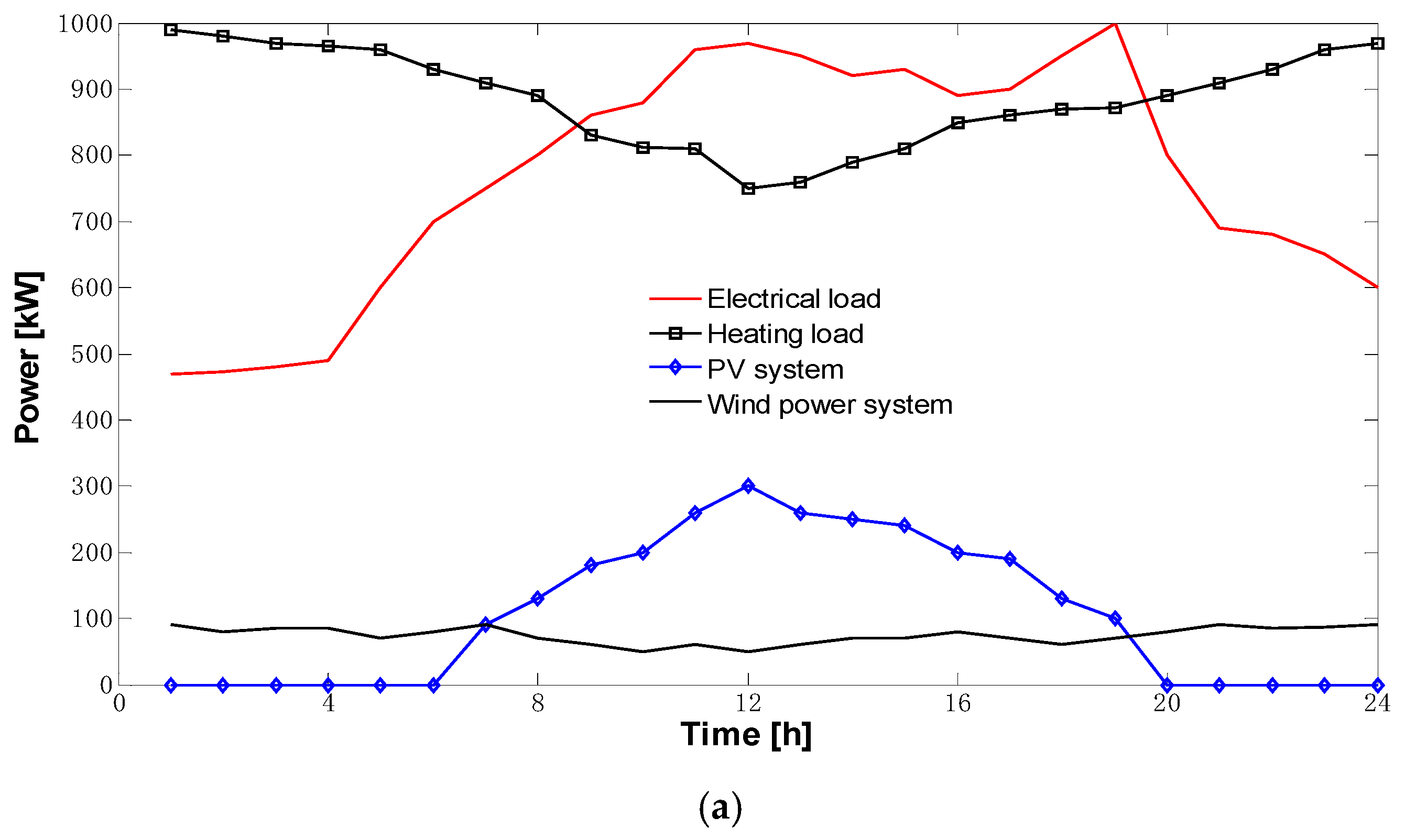
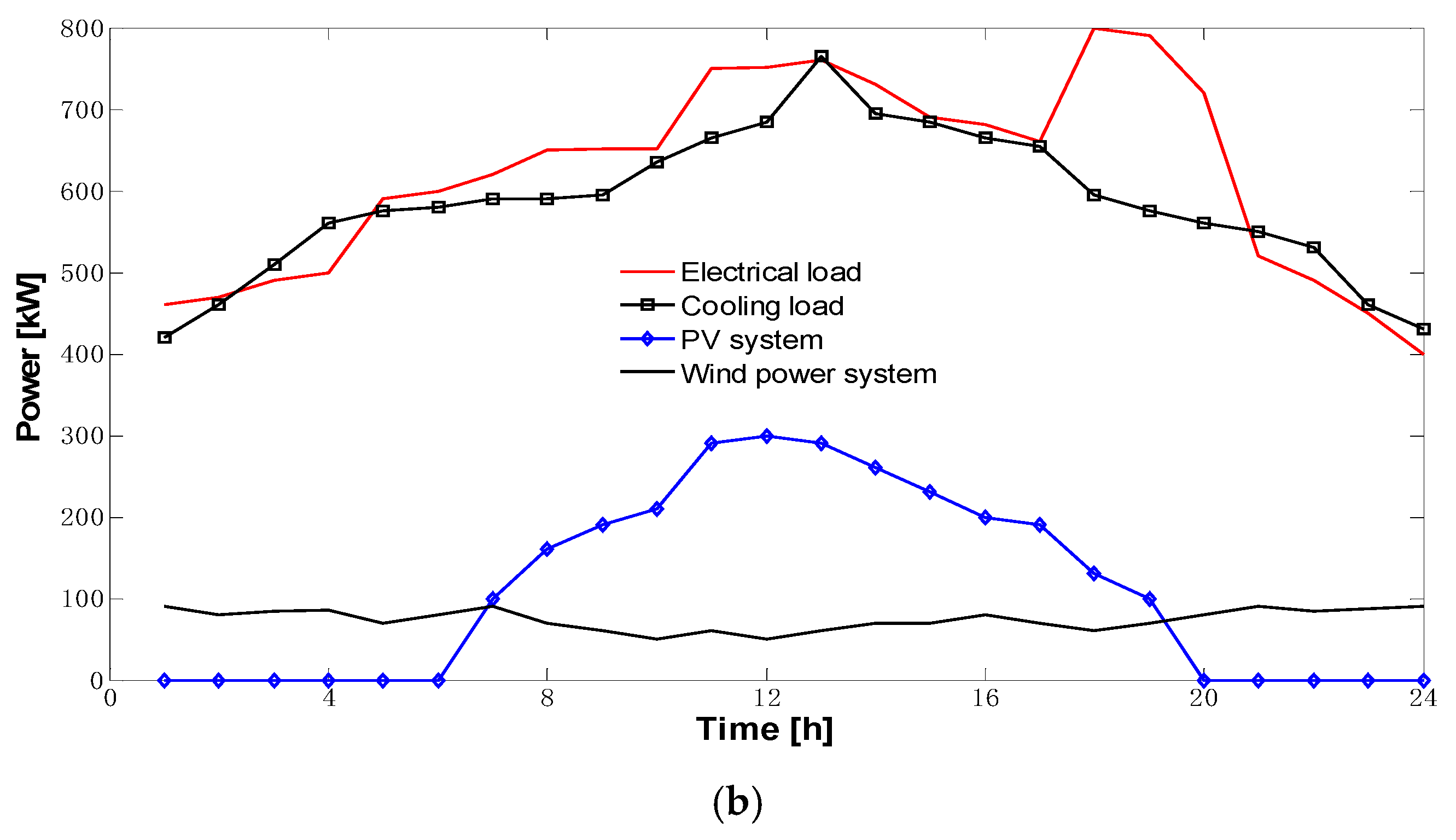
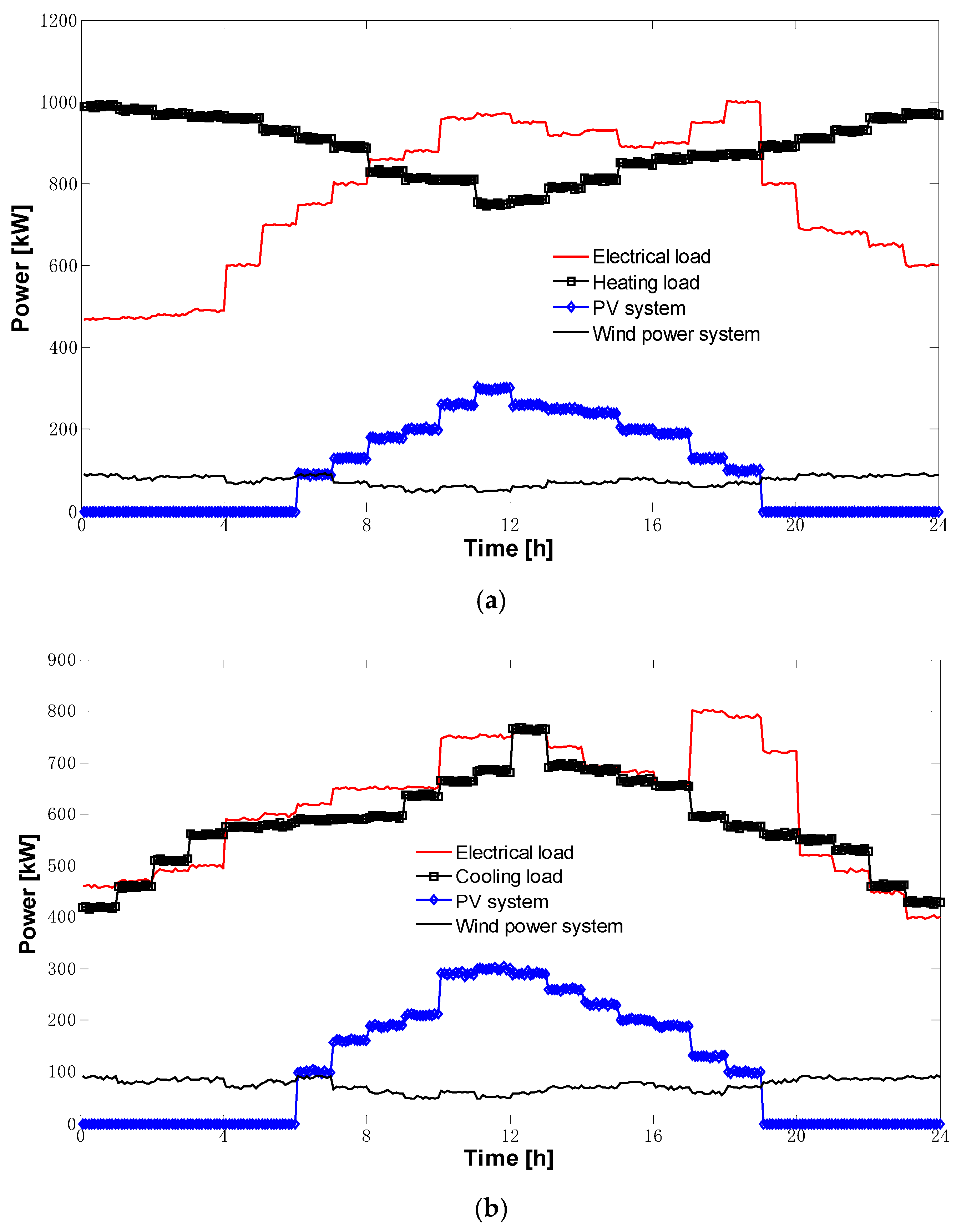
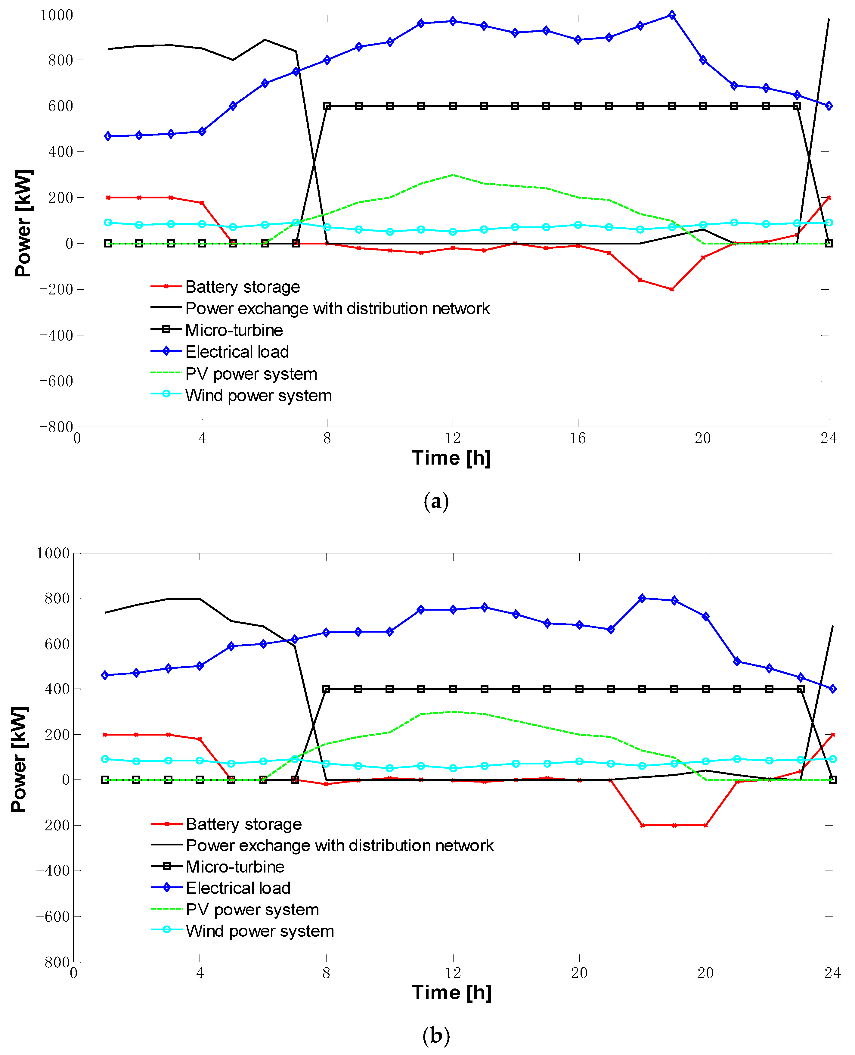
5. Case Study
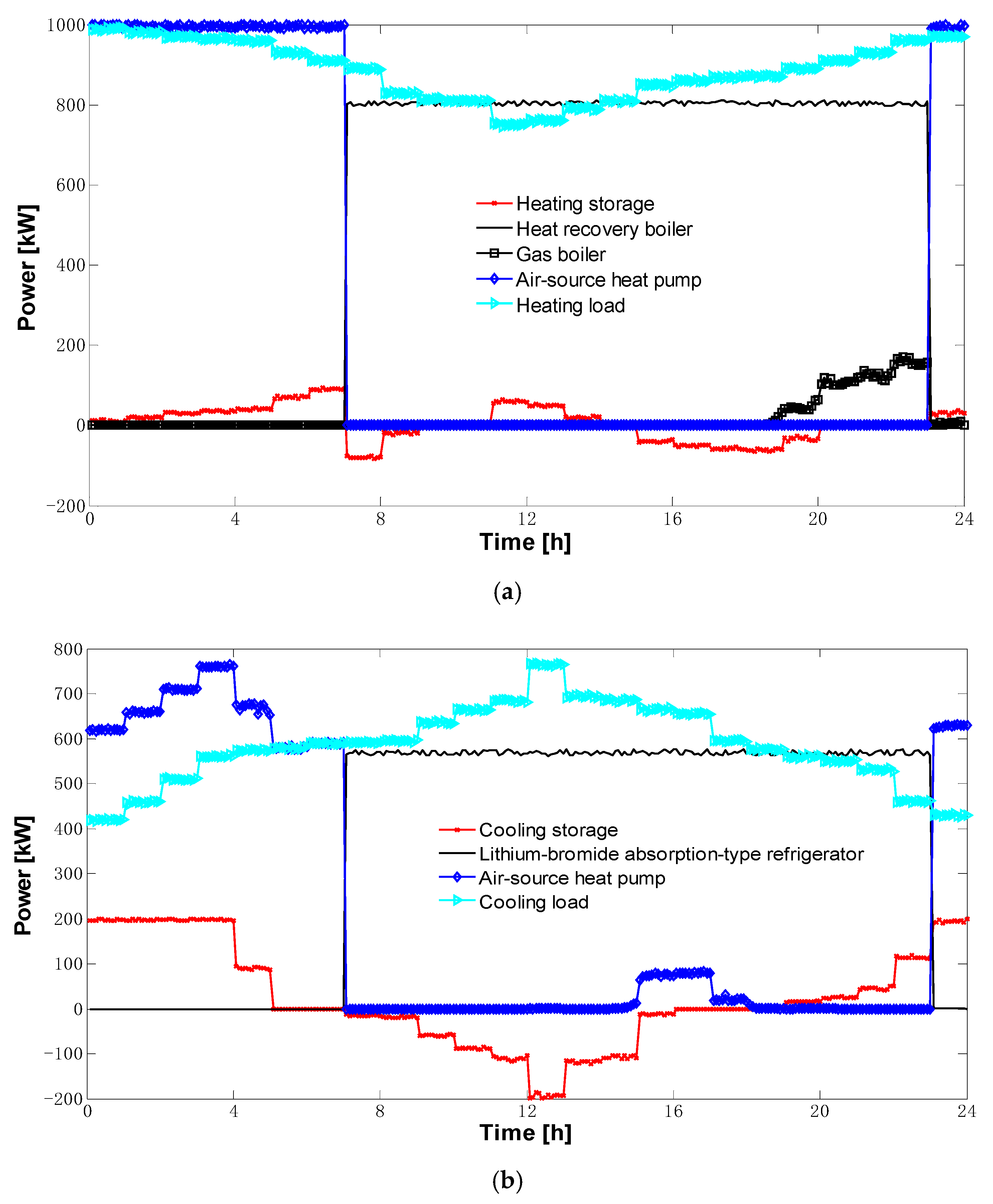
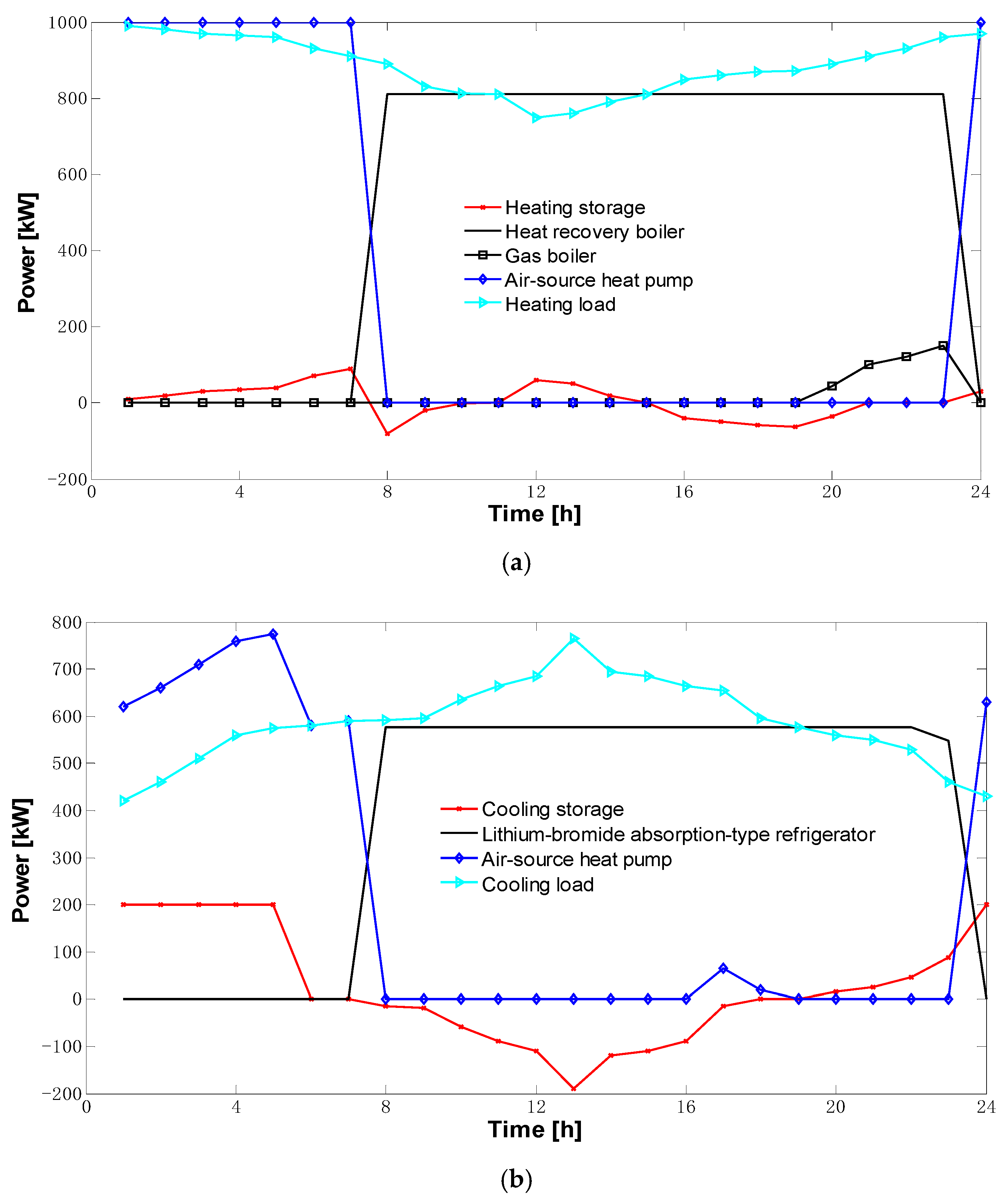
5.1. The Results of Day-Ahead Optimal Dispatch
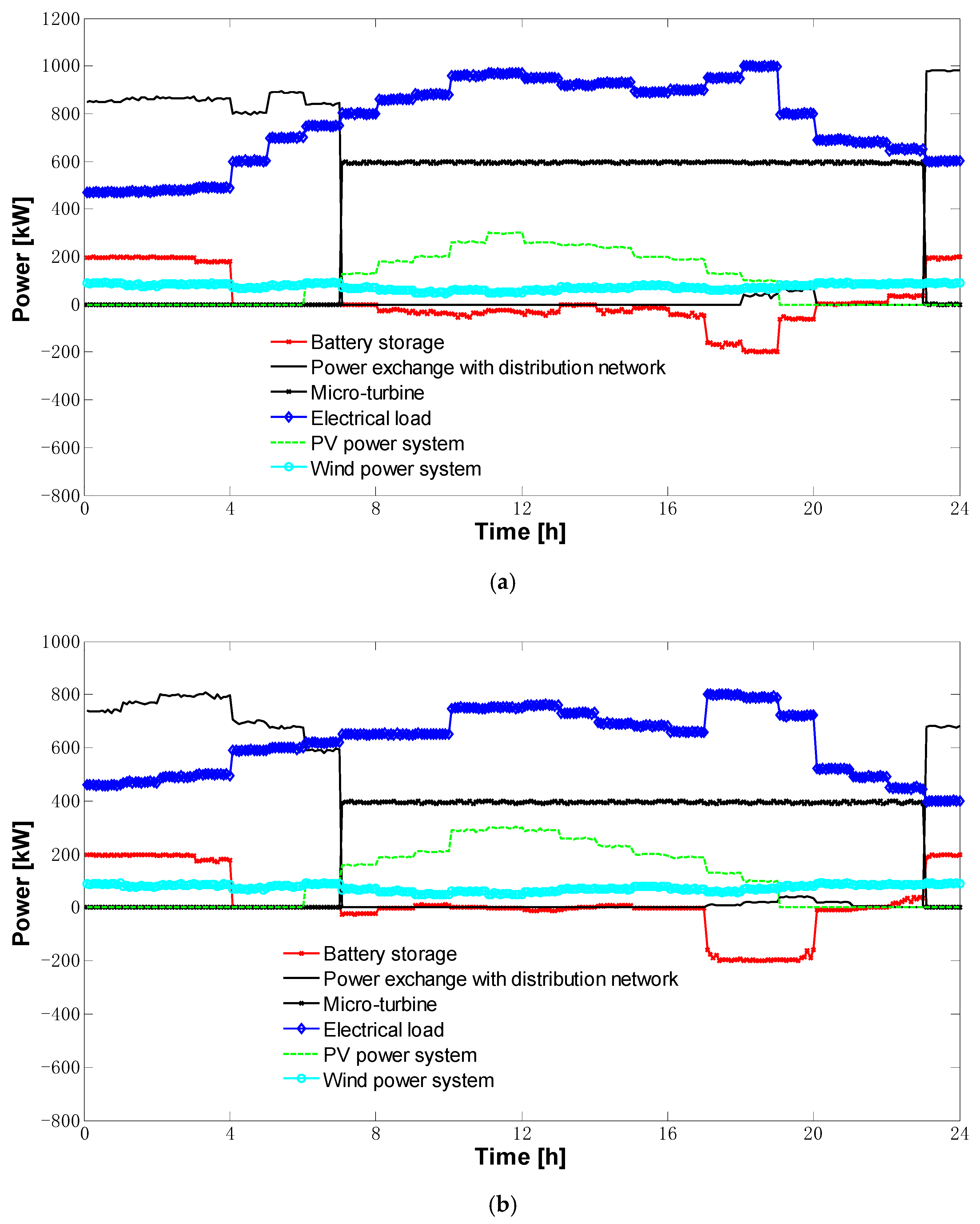
5.2. The Results of Real-Time Optimal Dispatch
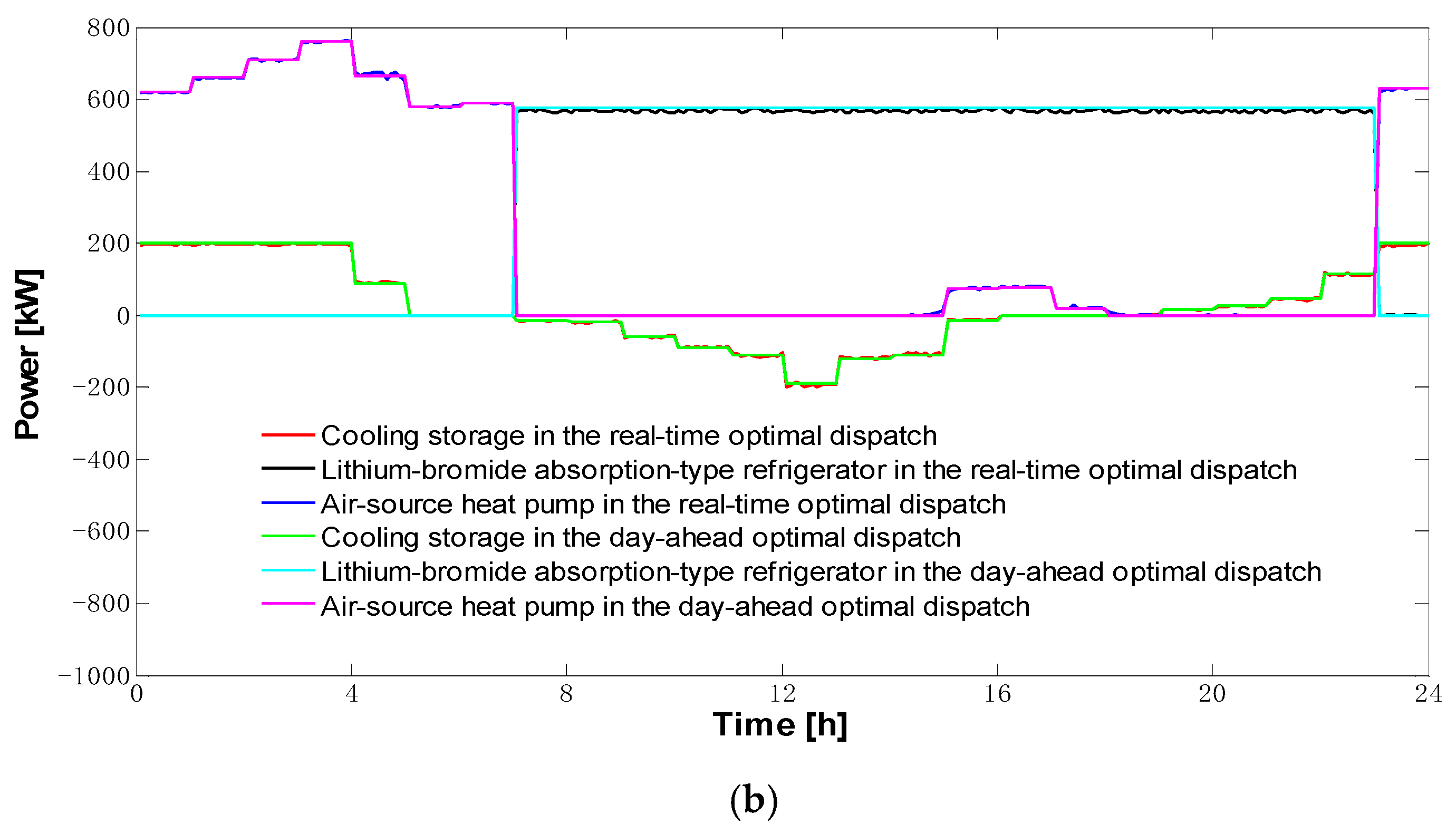
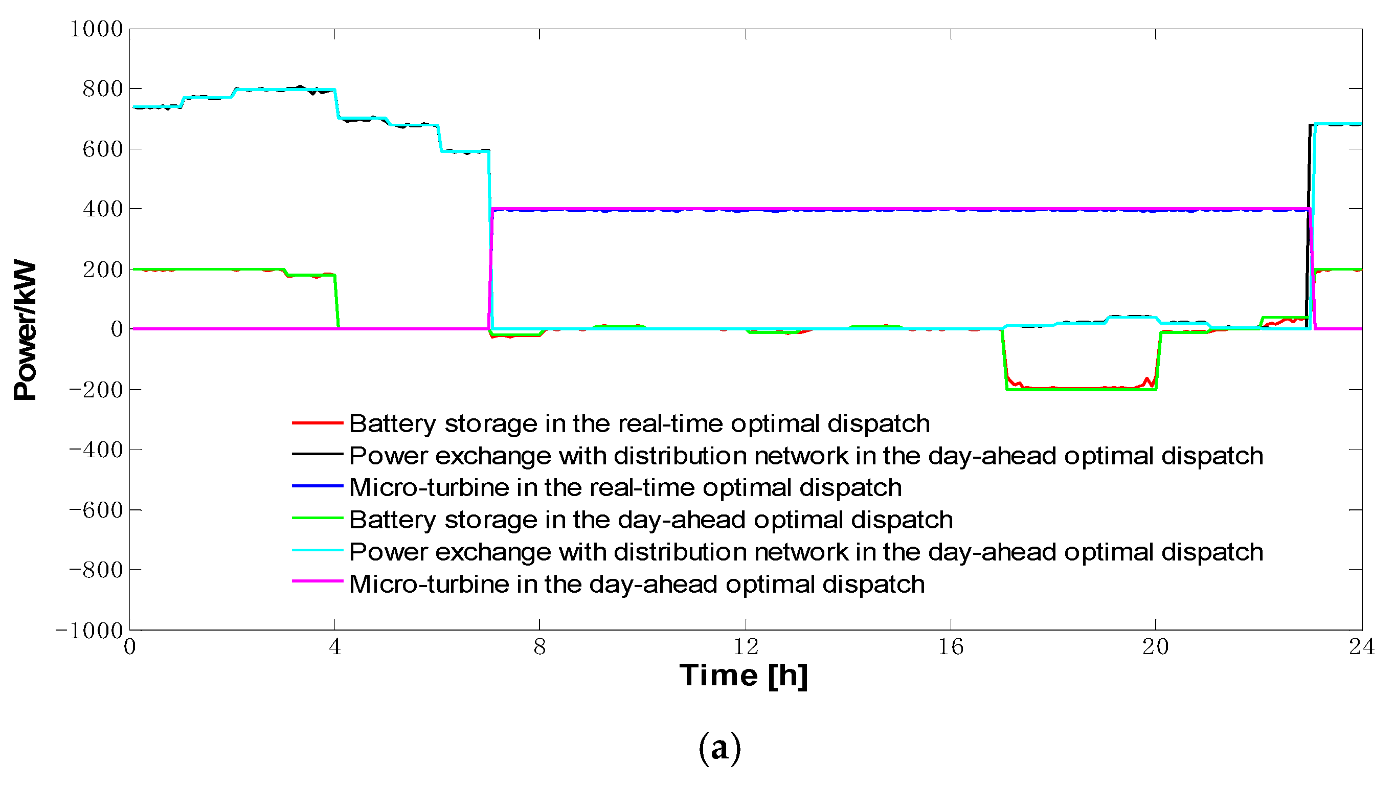
5.3. Comparison of Optimal Results between the Day-Ahead Optimal Dispatch and the Real-Time Optimal Dispatch
6. Conclusions
Author Contributions
Funding
Conflicts of Interest
Nomenclature
| difference between the cost of purchasing electricity and the income of selling electricity for the micro-energy-grid | |
| maintenance cost of the micro-energy-grid | |
| cost of environmental pollution | |
| cost of purchasing biogas | |
| electricity purchasing price of the micro-energy-grid | |
| electricity selling price of the micro-energy-grid | |
| power exchange between the micro-energy-grid and the distribution network (purchasing electricity power is positive, and selling electricity power is negative) | |
| heating power of the heat-recovery boiler | |
| heating power of the biogas-fired boiler | |
| electrical power of the battery storage device (discharge is negative and charge is positive) | |
| electrical power of the micro-turbine | |
| electrical power of the PV power generation system | |
| electrical power of the wind power generation system | |
| cooling power of the lithium-bromide absorption-type refrigerator | |
| heating power of the heating storage device (discharge is negative, and charge is positive) | |
| cooling power of the cooling storage device (discharge is negative, and charge is positive) | |
| electrical load | |
| electrical power of the air-source heat pump | |
| cooling power of the air-source heat pump | |
| heating power of the air-source heat pump | |
| heating load | |
| cooling load | |
| biogas price | |
| penalty of pollutant gas y | |
| environmental value of pollutant gas y | |
| emission value of pollutant gas y | |
| type of pollutant gas | |
| maintenance cost of the heat-recovery boiler | |
| maintenance cost of the biogas-fired boiler | |
| cost for storing energy in the battery storage device | |
| daily manual maintenance cost of the battery storage device | |
| maintenance cost of the micro-turbine | |
| maintenance cost of the PV power generation system | |
| maintenance cost of the wind power generation system | |
| maintenance cost of the lithium-bromide absorption-type refrigerators | |
| maintenance cost of the air-source heat pump | |
| maintenance cost of the heating storage device | |
| maintenance cost of the cooling storage device | |
| maximum electrical power of the micro-turbine | |
| maximum heating power of the heat-recovery boiler | |
| maximum heating power of the biogas-fired boiler | |
| maximum cooling power of the lithium-bromide absorption-type refrigerator | |
| downward climbing speed of the micro-turbine | |
| upward climbing speed of the micro-turbine | |
| downward climbing speed of the biogas-fired boiler | |
| upward climbing speed of the biogas-fired boiler | |
| value of the power generation efficiency of the micro-turbine | |
| value of the heating loss coefficient of the micro-turbine | |
| value of the recovery efficiency of the flue gas waste heat | |
| efficiency of the heat-recovery boiler | |
| efficiency of the lithium-bromide absorption-type refrigerator | |
| state of charge of the cooling–heating–electricity storage device | |
| self-discharging efficiency of the cooling–heating–electricity storage device | |
| charging power of the cooling–heating–electricity storage device | |
| discharging power of the cooling–heating–electricity storage device | |
| charging efficiencies of the cooling–heating–electricity storage device | |
| discharging efficiencies of the cooling–heating–electricity storage device | |
| dispatching period | |
| total capacity of the cooling–heating–electricity storage device | |
| minimum state of charge of the cooling–heating–electricity storage device | |
| maximum state of charge of the cooling–heating–electricity storage device | |
| maximum charging power of the cooling–heating–electricity storage device | |
| maximum discharging power of the cooling–heating–electricity storage device | |
| charging and discharging power of the cooling–heating–electricity storage device | |
| cooling efficiency of the air-source heat pump | |
| heating efficiency of the air-source heat pump | |
| maximum electrical power of the air-source heat pump | |
| minimum power exchange between the micro-energy-grid and the distribution network | |
| maximum power exchange between the micro-energy-grid and the distribution network | |
| system reserve rate | |
| power variation in the heat-recovery boiler | |
| power variation in the biogas-fired boiler | |
| power variation in the lithium-bromide absorption-type refrigerator | |
| power variation in the micro-turbine | |
| power variation in the air-source heat pump | |
| power variation in the wind power generation system | |
| power variation in the PV generation system | |
| power variation in the electrical load | |
| cost for storing energy in the battery storage device | |
| electricity selling price of the PV and wind power generation system | |
| electricity selling price of the micro-turbine | |
| power exchange between the micro-energy-grid and the distribution network in the day-ahead optimal dispatch | |
| charging and discharging power of the battery storage device in the day-ahead optimal dispatch | |
| state of charge of the battery storage device in the day-ahead optimal dispatch | |
| charging and discharging power of the cooling storage device in the day-ahead optimal dispatch | |
| state of charge of the cooling storage device in the day-ahead optimal dispatch | |
| charging and discharging power of the heating storage device in the day-ahead optimal dispatch | |
| state of charge of the heating storage device in the day-ahead optimal dispatch | |
| power of the heat-recovery boiler in the day-ahead optimal dispatch | |
| power of the biogas-fired boiler in the day-ahead optimal dispatch | |
| power of the lithium-bromide absorption-type refrigerator in the day-ahead optimal dispatch | |
| power of the micro-turbine in the day-ahead optimal dispatch | |
| power of the air-source heat pump in the day-ahead optimal dispatch | |
| minimum power variation in the heat-recovery boiler | |
| maximum power variation in the heat-recovery boiler | |
| minimum power variation in the biogas-fired boiler | |
| maximum power variation in the biogas-fired boiler | |
| minimum power variation in the lithium-bromide absorption-type refrigerator | |
| maximum power variation in the lithium-bromide absorption-type refrigerator | |
| minimum power variation in the micro-turbine | |
| maximum power variation in the micro-turbine | |
| minimum power variation in the air-source heat pump | |
| maximum power variation in the air-source heat pump | |
| minimum charging and discharging power variation in the battery storage device | |
| maximum charging and discharging power variation in the battery storage device | |
| minimum charging and discharging power variation in the cooling storage device | |
| maximum charging and discharging power variation in the cooling storage device | |
| minimum charging and discharging power variation in the heating storage device | |
| maximum charging and discharging power variation in the heating storage device | |
| maximum charging and discharging power of the battery storage device | |
| minimum charging and discharging power of the battery storage device | |
| maximum charging and discharging power of the cooling storage device | |
| minimum charging and discharging power of the cooling storage device | |
| maximum charging and discharging power of the heating storage device | |
| minimum charging and discharging power of the heating storage device | |
| minimum state of charge of the battery storage device | |
| maximum state of charge of the battery storage device | |
| minimum state of charge of the cooling storage device | |
| maximum state of charge of the cooling storage device | |
| minimum state of charge of the heating storage device | |
| maximum state of charge of the heating storage device | |
| total capacity of electricity storage device | |
| total capacity of cooling storage device | |
| total capacity of heating storage device | |
| self-discharging efficiency of the battery storage device | |
| self-discharging efficiency of the cooling storage device | |
| self-discharging efficiency of the heating storage device | |
| charging and discharging efficiency of the battery storage device | |
| charging and discharging efficiency of the cooling storage device | |
| charging and discharging efficiency of the heating storage device |
| PV | photovoltaic |
References
- He, Y.B.; Yan, M.Y.; Shahidehpour, M.; Li, Z.Y.; Guo, C.X.; Wu, L.; Ding, Y. Decentralized optimization of multi-area electricity-natural gas flows based on cone reformulation. IEEE Trans. Power Syst. 2018, 33, 4531–4542. [Google Scholar] [CrossRef]
- Rashidi, H.; Khorshidi, J. Exergoeconomic analysis and optimization of a solar based multigeneration system using multiobjective differential evolution algorithm. J. Clean. Prod. 2018, 170, 978–990. [Google Scholar] [CrossRef]
- Li, Y.; Yang, Z.; Li, G.Q.; Zhao, D.B.; Tian, W. Optimal scheduling of an isolated microgrid with battery storage considering load and renewable generation uncertainties. IEEE Trans. Ind. Electron. 2019, 66, 1565–1575. [Google Scholar] [CrossRef]
- Hosseinzadeh, M.; Salmasi, F.R. Fault-tolerant supervisory controller for a hybrid ac/dc micro-grid. IEEE Trans. Smart Grid 2018, 9, 2809–2823. [Google Scholar] [CrossRef]
- Jeremy, R. Third Industrial Revolution: How Lateral Power Is Transforming Energy, the Economy, and the World; Palgrave Macmillan Trade: New York, NY, USA, 2011; pp. 33–72. [Google Scholar]
- Fu, X.Q.; Zhang, X.R. Failure probability estimation of gas supply using the central moment method in an integrated energy system. Appl. Energy 2018, 219, 1–10. [Google Scholar] [CrossRef]
- Li, Z.M.; Xu, Y. Optimal coordinated energy dispatch of a multi-energy microgrid in grid-connected and islanded modes. Appl. Energy 2018, 210, 974–986. [Google Scholar] [CrossRef]
- Mi, Y.; Liu, H.Y.; Song, G.X.; Li, Z.Q.; Fu, Y.; Li, Z.K. Two-layer power optimization allocation of multi-energy local networks oriented to energy internet. Power Autom. Equip. 2018, 38, 1–10. [Google Scholar]
- Ding, T.; Mu, C.L.; Bie, Z.H.; Du, P.W.; Fan, Z.Y.; Zou, Z.X.; Yang, Y.H.; Wu, Z.Y.; Xu, Y.; Tang, B.G. Review of energy internet and its operation. Proc. CSEE 2018, 38, 4318–4328. [Google Scholar]
- Chen, S.; Wei, Z.N.; Sun, G.G.; Sun, Y.L.; Zang, H.X.; Zhu, Y. Optimal power and gas how with a limited number of control actions. IEEE Trans. Smart Grid 2018, 9, 5371–5380. [Google Scholar] [CrossRef]
- Habibollahzade, A.; Gholamian, E.; Ahmadi, P.; Behzadi, A. Multi-criteria optimization of an integrated energy system with thermoelectric generator, parabolic trough solar collector and electrolysis for hydrogen production. Int. J. Hydrog. Energy 2018, 43, 14140–14157. [Google Scholar] [CrossRef]
- Qiu, J.; Zhao, J.H.; Yang, H.M.; Wang, D.X.; Dong, Z.Y. Planning of solar photovoltaics, battery energy storage system and gas micro turbine for coupled micro energy grids. Appl. Energy 2018, 219, 361–369. [Google Scholar] [CrossRef]
- Meesenburg, W.; Ommen, T.; Elmegaard, B. Dynamic exergoconomic analysis of a heat pump system used for ancillary services in an integrated energy system. Energy 2018, 152, 154–165. [Google Scholar] [CrossRef]
- Li, S.X.; Hu, M.H.; Gong, C.C.; Zhan, S.; Qin, D.T. Energy Management Strategy for Hybrid Electric Vehicle Based on Driving Condition Identification Using KGA-Means. Energies 2018, 11, 1531. [Google Scholar] [CrossRef]
- Hosseinzadeh, M.; Salmasi, F.R. Robust Optimal Power Management System for a Hybrid AC/DC Micro-Grid. IEEE Trans. Sustain. Energy 2015, 6, 675–687. [Google Scholar] [CrossRef]
- Zhang, X.; Yang, J.H.; Wang, W.Z.; Jing, T.J.; Zhang, M. Optimal operation analysis of the distribution network comprising a micro energy grid based on an improved grey wolf optimization algorithm. Appl. Sci. 2018, 8, 923. [Google Scholar] [CrossRef]
- Chan, D.; Cameron, M.; Yoon, Y. Implementation of micro energy grid: A case study of a sustainable community in China. Energy Build. 2017, 139, 719–731. [Google Scholar] [CrossRef]
- Wang, H.; Ai, Q.; Wu, J.H.; Xie, Y.Z.; Zhou, X.Q. Bi-level distributed optimization for microgrid clusters based on alternating direction method of multipliers. Power Syst. Technol. 2018, 42, 1718–1727. [Google Scholar]
- Yang, L.J.; Li, H.Q.; Yu, X.Y.; Zhao, J.S.; Liu, W.Y. Multi-objective day-ahead optimal scheduling of isolated microgrid considering flexibility. Power Syst. Technol. 2018, 42, 1432–1440. [Google Scholar]
- Bharothu, J.N.; Sridhar, M.; Rao, R.S. Modified adaptive differential evolution based optimal operation and security of AC-DC microgrid systems. Int. J. Electr. Power Energy Syst. 2018, 103, 185–202. [Google Scholar] [CrossRef]
- Gao, R.; Wu, J.; Hu, W.; Zhang, Y. An improved ABC algorithm for energy management of microgrid. Int. J. Comput. Commun. Control 2018, 13, 477–491. [Google Scholar] [CrossRef]
- Hemmati, M.; Mohammadi-Ivatloo, B.; Ghasemzadeh, S.; Reihani, E. Risk- based optimal scheduling of reconfigurable smart renewable energy based microgrids. Int. J. Electr. Power Energy Syst. 2018, 101, 415–428. [Google Scholar] [CrossRef]
- Chen, G.; Yang, Q. An ADMM-based distributed algorithm for economic dispatch in islanded microgrids. IEEE Trans. Ind. Inform. 2018, 14, 3892–3903. [Google Scholar] [CrossRef]
- Lu, X.H.; Zhou, K.L.; Yang, S.L.; Liu, H.Z. Multi-objective optimal load dispatch of microgrid with stochastic access of electric vehicles. J. Clean. Prod. 2018, 195, 187–199. [Google Scholar] [CrossRef]
- Ma, T.F.; Wu, J.Y.; Hao, L.L. Energy flow modeling and optimal operation analysis of the micro energy grid based on energy hub. Energy Convers. Manag. 2017, 133, 292–306. [Google Scholar] [CrossRef]
- Lin, K.J.; Wu, J.Y.; Hao, L.L.; Liu, D.; Li, D.Z.; Yan, H.G. Optimization of operation strategy for micro-energy grid with cchp systems based on non-cooperative game. Autom. Electr. Power Syst. 2018, 42, 25–32. [Google Scholar]
- Ghasmi, A.; Banejad, M.; Rahimiyan, M. Integrated energy scheduling under uncertainty in a micro energy grid. IET Gener. Transm. Distrib. 2018, 12, 2887–2896. [Google Scholar] [CrossRef]
- Li, D.Z.; Wu, J.Y.; Shi, K.; Ma, T.F.; Zhang, Y.; Zhang, R.Y. Bi-level optimal dispatch model for micro energy grid based laod aggregator business. In Proceedings of the 2017 IEEE Conference on Energy Internet and Energy System Integration (EI2), Beijing, China, 26–28 November 2017; pp. 643–648. [Google Scholar]
- Wang, W.Z.; Liu, F.C.; Zheng, J.J.; Yanf, Y.; Zhang, J.H.; Yang, J.H.; Jing, T.J. Optimal regulation on micro energy grid based on time-shifting agricultural load. In Proceedings of the 2017 IEEE Conference on Energy Internet and Energy System Integration (EI2), Beijing, China, 26–28 November 2017; pp. 42–47. [Google Scholar]
- Wang, Y.Z.; Niu, H.N.; Yang, L.; Wang, W.Z.; Liu, F.C. An optimization method for local consumption of photovoltaic powr in a facility agriculture micro energy network. Energies 2018, 11, 1503. [Google Scholar] [CrossRef]
- Wu, X.; Wang, X.L.; Bie, Z.H.; Wang, J.X. Economic operation of microgrid with combined heat and power system. Electr. Power Autom. Equip. 2013, 33, 1–6. [Google Scholar]
- Xu, Q.S.; Zeng, A.D.; Wang, K.; Jiang, L. Day-ahead optimized economic dispatching for combined cooling, heating and power in micro energy-grid based on hessian interior point method. Power Syst. Technol. 2016, 40, 1657–1665. [Google Scholar]
- Zhao, J.; Yang, H.H.; Ye, D.F.; Qing, W.C. Research on energy system based on CCHP coupled with energy storage. Energy Convers. Technol. 2016, 34, 120–124. [Google Scholar]
- Wang, C.; Gu, W.; Wu, Z. Economic and optimal operation of a combined heat and power micro grid with renewable energy resources. Autom. Electr. Power Syst. 2011, 35, 22–27. [Google Scholar]
- Ma, X.Y.; Wu, Y.W.; Fang, H.L.; Sun, Y.Z. Optimal sizing of hybrid solar-wind distributed generation in an islanded microgrid using improved bacterial foraging algorithm. Proc. CSEE 2011, 31, 17–25. [Google Scholar]
- Xian, X.; Fan, C.G.; Wen, S.S.; Wang, Y.C.; Chen, C.; Liu, X. Optimal deployment for island microgrid considering probabilistic factors of renewable energy generations. Eng. J. Wuhan Univ. 2016, 49, 101–104. [Google Scholar]
- Pazouki, S.; Haghifam, M.R.; Moser, A. Uncertainty modeling in optimal operation of energy hub in presence of wind, storage and demand response. Int. J. Electr. Power Energy Syst. 2014, 61, 335–345. [Google Scholar] [CrossRef]


| Device | Parameter | Value |
|---|---|---|
| Micro turbine(six) | Maximum generated power (kW·one−1) | 100 |
| Rated efficiency | 0.26 | |
| Climbing speed (kW·min−1) | Upward 30, Downward 20 | |
| Heat-recovery boiler | Maximum input power (kW) | 900 |
| Rated efficiency | 0.9 | |
| Lithium-bromide absorption-type refrigerator | Maximum input power (kW) | 900 |
| Rated efficiency | 1.2 | |
| Biogas-fired boiler | Maximum input power (kW) | 500 |
| Rated efficiency | 0.8 | |
| Climbing speed (kW·min−1) | Upward 30, Downward 20 | |
| Air-source heat pumps for heating and cooling exchange | Maximum heating and cooling exchange power (kW) | 1000 |
| Heating and cooling efficiency parameter | 3.7 | |
| Power exchange between micro-energy-grid with external power grid | Maximum exchange power (kW) | 1000 |
| PV power generation system | Maximum generated power (kW) | 300 |
| Wind power generation system | Maximum generated power (kW) | 100 |
| Device | Maintenance Cost (RMB·(kW·h)−1) |
|---|---|
| Micro turbine | 0.03 |
| Heat-recovery boiler | 0.02 |
| Lithium-bromide absorption-type refrigerator | 0.025 |
| Biogas-fired boiler | 0.02 |
| Air-source heat pump | 0.02 |
| PV power generation system | 0.03 |
| Wind power generation system | 0.03 |
| Battery storage device | 0.03 |
| Heating storage device | 0.02 |
| Cooling storage device | 0.02 |
| Storage Device Parameter | Electricity-Cooling-Heating Efficiency | Self-Discharging Efficiency of Cooling-Heating-Electricity | State of Charge of Cooling-Heating-Electricity | Capacity (kW·h) | ||
|---|---|---|---|---|---|---|
| Max Charge | Max Discharge | Maximum | Minimum | |||
| Battery storage device | 0.2 | 0.2 | 0.02 | 0.9 | 0.2 | 1000 |
| Heating storage device | 0.2 | 0.2 | 0.03 | 0.9 | 0.1 | 1000 |
| Cooling storage device | 0.2 | 0.2 | 0.03 | 0.9 | 0.1 | 1000 |
| Device | Price (RMB·(kW·h)−1) |
|---|---|
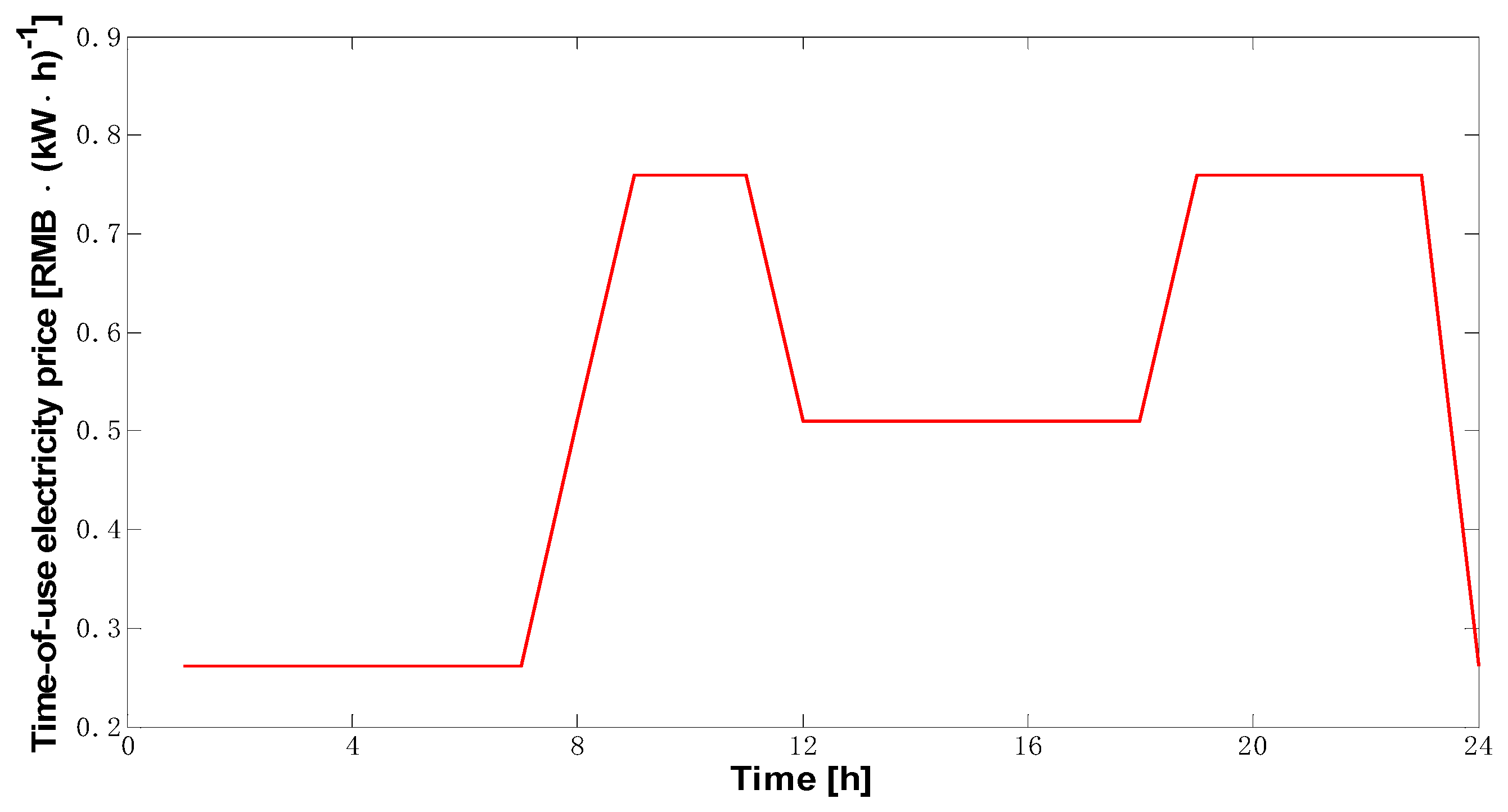
| Micro turbine | 0.2610 (23:00–24:00, 00:00–07:00) 0.5100 (07:00–08:00, 11:00–18:00) 0.7590 (08:00–11:00, 18:00–23:00) |
| PV and wind power generation system | 0.8610 (23:00–24:00, 00:00–07:00) 1.1100 (07:00–08:00, 11:00–18:00) 1.3590 (08:00–11:00, 18:00–23:00) |
© 2018 by the authors. Licensee MDPI, Basel, Switzerland. This article is an open access article distributed under the terms and conditions of the Creative Commons Attribution (CC BY) license (http://creativecommons.org/licenses/by/4.0/).
Share and Cite
Zhang, X.; Yang, J.; Wang, W.; Zhang, M.; Jing, T. Integrated Optimal Dispatch of a Rural Micro-Energy-Grid with Multi-Energy Stream Based on Model Predictive Control. Energies 2018, 11, 3439. https://doi.org/10.3390/en11123439
Zhang X, Yang J, Wang W, Zhang M, Jing T. Integrated Optimal Dispatch of a Rural Micro-Energy-Grid with Multi-Energy Stream Based on Model Predictive Control. Energies. 2018; 11(12):3439. https://doi.org/10.3390/en11123439
Chicago/Turabian StyleZhang, Xin, Jianhua Yang, Weizhou Wang, Man Zhang, and Tianjun Jing. 2018. "Integrated Optimal Dispatch of a Rural Micro-Energy-Grid with Multi-Energy Stream Based on Model Predictive Control" Energies 11, no. 12: 3439. https://doi.org/10.3390/en11123439
APA StyleZhang, X., Yang, J., Wang, W., Zhang, M., & Jing, T. (2018). Integrated Optimal Dispatch of a Rural Micro-Energy-Grid with Multi-Energy Stream Based on Model Predictive Control. Energies, 11(12), 3439. https://doi.org/10.3390/en11123439