Article

Novel High Step-Up DC–DC Converter with Three-Winding-Coupled-Inductors and Its Derivatives for a Distributed Generation System

1
School of Electrical and Information, Northeast Agricultural University, Harbin 150030, China
2
School of Electrical Engineering and Automation, Harbin Institute of Technology, Harbin 150001, China
3
School of Electrical Engineering, Southeast University, Nanjing 210096, China
*
Author to whom correspondence should be addressed.
Energies 2018, 11(12), 3428; https://doi.org/10.3390/en11123428
Submission received: 28 September 2018 / Revised: 20 October 2018 / Accepted: 25 October 2018 / Published: 7 December 2018
(This article belongs to the Section F: Electrical Engineering)

Abstract

:
A novel step-up DC-DC converter with a three-winding-coupled-inductor which integrates a coupled-inductor and voltage-boost techniques for a distributed generation system is proposed in this paper. The two windings of the dotted terminal connection are charged by the input source; the proposed converter utilized smaller turn ratios, and can achieve higher gain when the active switch is turned on. The passive lossless clamped circuits not only can absorb the leakage energy, but also lower the switch voltage stresses; additionally, the reverse-recovery problem of diodes can be reduced to improve the system efficiency. Furthermore, the voltage stress of the output capacitor is reduced. The operating principle and corresponding theoretical analyses are discussed in detail. Finally, an experimental prototype with 50 kHz switching frequency, 40 V input voltage, 380 V output voltage and 400 W output power is set up to verify the validity of the proposed converter.

1. Introduction

In recent times, in order to reducing pollution caused by fossil fuels, new, clean, renewable energy systems have been rapidly developed. Multilevel inverters with higher performance and corresponding analysis methods are presented, and have been widely applied for many circumstances [1,2]. But new renewable energies can’t provide higher DC voltage; DC-DC converters with high step-up voltage gains and high efficiencies must be connected between lower input DC voltage and inverters [3,4,5,6,7].
In theory, the basic boost converter with unlimited voltage gain is a preferable candidate, but the higher voltage gain will use the higher duty cycle ratio, which will result in many serious problems such as the reverse-recovery of diodes, higher losses, and higher voltage stress across passive components [8,9]. Boost converters in series are presented to realize the higher voltage gain, but this results in complicated systems and influences reliability due to the presence of additional switches and control units [10,11,12]. Quadratic boost converters based on cascaded technology can improve voltage gain and are applied extensively, but two switches and control circuits in quadratic boost converters increase the complexity and cost of systems, and the voltage gain still needs to be improved to meet many application circumstances.
Some DC-DC converters with coupled-inductor cells are presented to realize higher voltage gains [13,14,15,16,17,18,19,20,21,22,23,24,25]. In [13], the converter gain is achieved via a switched capacitor, but this increases the conduction loss and reduces efficiency. In [14], the voltage gain of this converter was extend by switched inductor technology; however, the voltage stress on the switches will stay at a high level, and thus, the active switches induce serious conduction losses. In [15,16,17], a voltage lift technique has been proposed. By the voltage-double capacitor, the voltage-boost ability is increased; unfortunately, the capacitor will suffer high voltage and current stresses. In [18], the switched capacitor and switched inductor technique are used to realize high step-up voltage gains, but they lead to larger power losses. The improved coupled inductor DC-DC converters with two winding and three winding coupled-inductor cells are presented to realize higher voltage gains, but the switches are placed at the output diode to higher switch voltage stresses [19,20].
By adjusting the turn ratio of a coupled inductor, the converter can obtain a high step-up voltage gain in [21], but, on the down side, the leakage inductor will cause a high voltage spike on the active switches. To resolve this weakness, an active clamp circuit is presented in [22,23]. However, the active clamp circuit does not achieve the step-up voltage, reduces efficiency, and adds extra cost. In [24,25,26], the converter can recycle the energy of the leakage inductor and improve the performance by using a negative clamp circuit to increase efficiency.
In this paper, a novel high step-up converter with a smaller turn ratio is proposed, and can achieve higher gain through coupled inductor technology and voltage lift technology, which will be beneficial to connect the power grid and transmit renewable energy under broader application circumstances. The passive lossless clamped circuits not only can absorb the leakage energy, but also lower the switch voltage stresses; additionally, the reverse-recovery problem of diodes can be reduced to improve the system efficiency. In addition, the voltage stress of the output capacitor is reduced. The operating principle and corresponding theoretical analyses are discussed in detail. Finally, an experimental prototype with 50 kHz switching frequency, 40 V input voltage, 380 V output voltage and 400 W output power is set up to verify the validity of the proposed converter.

2. Proposed High Step-Up Converter and Corresponding Operating Principles

The integration processes of the proposed converter are shown in Figure 1. Figure 1a shows the conventional boost DC-DC converter. To improve the voltage gain, a two-winding coupled inductor boost converter is structured by replacing inductor L1 with two winding coupled inductors, whose topology is shown in Figure 1b. Through the addition of auxiliary diodes (D1 and D2) and capacitors (C1 and C2), the voltage-double two-winding coupled inductor boost converter are presented to further produce higher voltage gain, as shown in Figure 1c. So, through adding one winding N3 and the corresponding voltage-double capacitors and diodes, the proposed three-winding coupled inductor high step-up converter is constructed by a three-winding coupled inductors, a switch S, four diodes D1D4, and four capacitors C1C4, as shown in Figure 1d. Meanwhile, a passive clamped circuit which is made of C1 and D1 can suppress the voltage spike on the switch caused by inductor leakage, and recycle the inductor leakage energy. The capacitor C2 is used to step-up and reduced the voltage stress on the diode D3. The voltage stress of the capacitor C3 can be reduced by connection with the capacitor C4 in series.
Three-winding coupled-inductor cell can be modeled as an ideal transformer, and the following conditions are assumed:
(1)
The capacitors in this converter are large enough that the voltages of those capacitors can be considered constant in one period.
(2)
Switches and diodes are considered as ideal, and will not be discussed in transient states.
(3)
The coupled inductor’s coupling coefficient K is equal to LM/(LM + LK).
Figure 2 shows waveforms in one switching period in continuous conduction mode (CCM). The corresponding operation modes are described as follows:
(1) Mode I [t0, t1]: at t = t0, the switch S is turned on. D1, D2 and D4 are turned on, and D3 is off as shown in Figure 3a. In this interval, the power source charges the magnetizing inductor LM and the leakage inductor LK, and the currents i L M and i L K increase linearly. The current i N 2 is increased too. Meanwhile, the capacitor C2 is charged by the clamped capacitor C1, the source, and the winding N3. The capacitor C4 is powered by the winding N2. The capacitor C3 and the secondary-side winding N2 provide their energy to the load R. When i D 2 is equal to zero at t = t1, D2 is naturally turned off, and the operating mode ends.
(2) Mode II [t1, t2]: during this time interval, the switch S is still turned on. The current-flow path is shown in Figure 3b. D3 is still turned off. The currents i L M and i L K are still rising, and the winding N3 of the coupled inductor is charged by the input source. The energy of the load is supplied by the secondary-side winding N2 and the capacitor C3. When the switch is turned off, this operating mode ends.
(3) Mode III [t2, t3]: at t = t2, the switch S is turned off. Diodes D1 and D3 are turned on. Meanwhile, diodes D2 and D4 are turned off in Figure 3c. The energy of the clamped capacitor C1 is provided by the primary side N1 and secondary side winding N3 of the coupled inductor; thus the voltage of the switch S is clamped by the input source and clamped capacitor C1. The capacitor C3 is charged by the source and primary-side winding N1 and the secondary-side winding N2 of the coupled inductor and the multiplier capacitor C2. The energy of the load is supplied by the input source, the secondary-side winding N1 and the primary-side winding N2 of the coupled inductor and the multiplier capacitor C2 the capacitor C4. When the current i D 1 is equal to zero at t = t3, diode D1 is turned off, ending operating mode.
(4) Mode IV [t3, t4]: during this time interval, the switch S is still turned off. The current-flow path is shown in Figure 3d.The input source connects in series with the primary-side winding N1, the secondary-side winding N2 of the coupled inductor, the capacitor C2 and the capacitor C4 to provide energy for the load through D3. This mode ends at t = t4 when the switch S is turned on at the beginning of the next switching period.

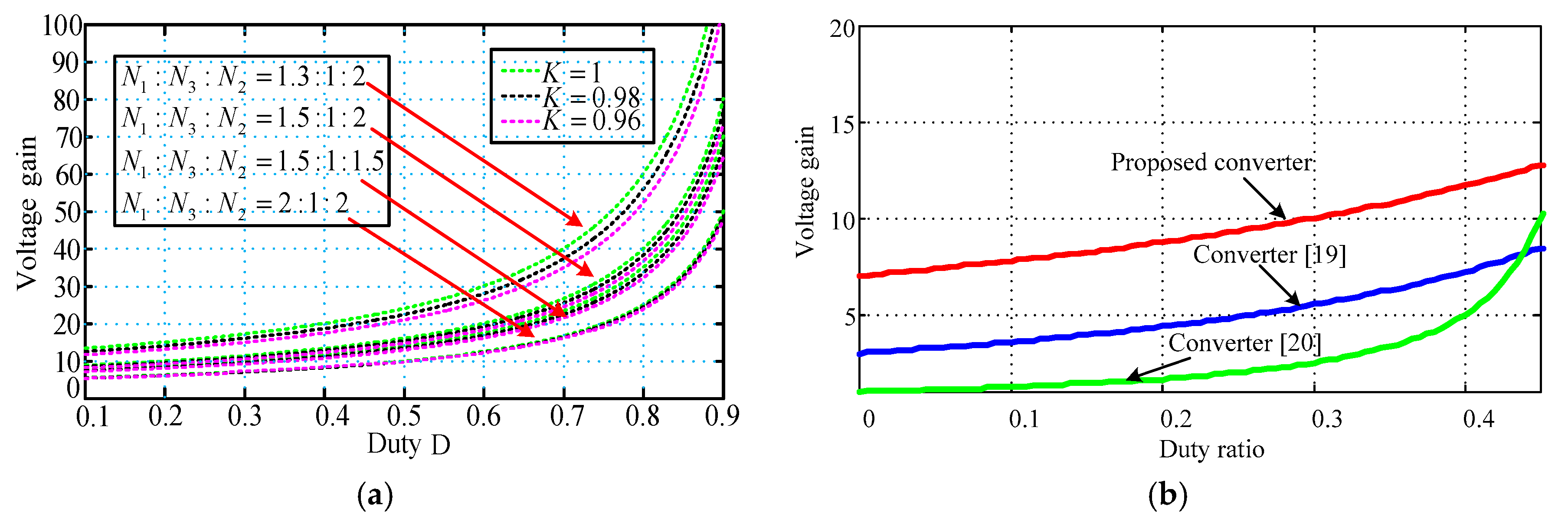
3. Steady-State Analysis

3.1. Analysis in Continuous Conduction Mode

In modes I and II based Figure 3a,b, the following equations can be obtained as follows:
V L M I = V L M II = N 1 K V in N 1 N 3 K
V L K I = V L K II = N 1 ( 1 K ) V in N 1 N 3 K
V C 2 = N 1 V in N 3 N 3 K + V C 1
V C 4 = N 2 K V in N 1 N 3 K
During the time of modes III and IV, the following equations can be expressed based on Figure 3c,d:
V C 1 = V L M III + V L K III + V C 1 = V L M IV + V L K IV + V C 1
V o = V in + ( 1 + N 3 K ) ( V L M III + V L K III ) + V C 2 + V C 4 = V in + ( 1 + N 3 K ) ( V L M IV + V L K IV ) + V C 2 + V C 4
Using the volt–second balance principle on LM and LK yields:
t 0 t 1 V L M I d t + t 1 t 2 V L M II d t + t 2 t 3 V L M III d t + t 3 t 4 V L M IV d t = 0
t 0 t 1 V L K I d t + t 1 t 2 V L K II d t + t 2 t 3 V L K III d t + t 3 t 4 V L K IV d t = 0
From Equations (1)–(10), the voltage gain can be expressed as:
M C C M = 2 N 1 N 3 K + N 2 K ( 1 D ) ( N 1 N 3 K ) = 2 n 31 K + n 21 K ( 1 D ) ( 1 n 31 K )
where n 21 = N 2 N 1 and n 31 = N 3 N 1 are the turns ratios of the proposed converter.
The relationship between the voltage gain, the duty ratio, and the coupling coefficients of coupled inductor is shown in Figure 4a. It shows that the coupling coefficient results in a decline of voltage gain. It can be seen clearly that a smaller turns ratios can achieve a higher gain. If the coupled coefficient K is equal to 1 without considering the impact of the leakage inductance of the coupled inductor, then the ideal voltage gain can be expressed as:
M C C M = 2 N 1 N 3 + N 2 ( 1 D ) ( N 1 N 3 ) = 2 n 31 + n 21 ( 1 D ) ( 1 n 31 )
In Figure 4b, the curve shows voltage gain comparisons among the proposed converter and the converters in [19,20] at CCM operation under N3:N2:N1 = 2:1:4. As shown in Figure 4b, the proposed converter has the higher voltage gain compared to the converters in [19,20], when using the same turn ratios and duty ratios.
In the proposed converter, the following inequalities are satisfied:
N 1 > N 3 > 0
When the winding turns N2 and N3 are changed, some converters are derived as follows.
In the proposed converter, the diode D4 is turned on during one switching period when N3 = 0. At the same time, the capacitor C4 can be ignored because the across its voltage is equal to zero. Therefore Figure 5 can be obtained. The voltage gains of converters in Figure 5a–c under different winding turns are listed in Table 1.

3.2. Voltage Stress Analysis

The switch voltage stresses, voltages of capacitors C1C4 and diodes D1D4 are expressed as follows:
V S = 1 1 D V in
V D 1 = V C 1 = D 1 D V in
V D 2 = V in ( 1 D ) ( 1 n 31 )
V D 3 = V C 3 = ( 1 + n 21 ) V in ( 1 D ) ( 1 n 31 )
V D 4 = n 21 V in ( 1 D ) ( 1 n 31 )
V C 2 = ( 1 n 31 D ) V in ( 1 D ) ( 1 n 31 )
V C 4 = n 21 V in 1 n 31

4. Derivative Converters

According to the different connection position, the proposed circuits can be derived in Figure 6. When applying series-connected voltage-lift networks (VLN), the voltage gain is enhanced by adding some VLN modules in Figure 6a. The voltage gain equation is derived from:
M C C M = 2 N 1 N 2 + N 3 + + N n ( 1 D ) ( N 1 N 2 )
Likewise, the voltage gain can be directly enlarged by applying a multiple windings coupled-inductor and multiple diode-capacitor networks to the proposed converter, as shown in Figure 6b. The voltage gain equation can be expressed as follows:
M C C M = 2 N 1 N 2 + N 3 + + N n ( 1 D ) ( N 1 N 2 )
The converter with a high step-up voltage gain also can be obtained by an input-parallel-output-series technique. In this technique, the primary and second winding of the coupled-inductor are parallel charged when switch is turned on, and discharged in series when it is turned off. The improved topology is shown in Figure 6c. The detailed features of the aforementioned improved converters are listed in Table 2. The voltage gain equation can be expressed as follows:
M C C M = 4 N 1 2 N 3 + N 2 ( 1 D ) ( N 1 N 3 )

5. Experimental Verifications

An experimental prototype with 50 kHz switching frequency, 40 V input voltage, 380 V output voltage and 400 W output power is set up and corresponding parameters have been listed in Table 3.
Duty cycle of the switch is about 0.58, and the switch voltage are about 87 V, as shown in Figure 7a. The switch voltage of active switch S and the voltage of primary winding N1 of the coupled inductor are shown in Figure 7b; it can be seen that the winding N1 are charged when the active switch S is turned on. The peak voltages of diodes (D1, D2, D3 and D4) are about 97 V, 193 V, 255 V, and 90 V, as shown in Figure 7c–f. From Figure 7c–f, it can be also seen that the current waveforms of diodes (D1, D2, D3 and D4) are consistent with theory analysis. It shows that the currents of diodes (D1, D2, D3 and D4) are decreased to zero quickly when the diodes are turned off, which means that losses can be reduced. The winding currents of the three-winding coupled inductor is shown in Figure 7a,g. As shown in Figure 7a,g, the operation states of three windings (N1, N2, N3) are consistent with theory analysis through the switch sequence of active switch S.
Figure 8 shows the tested efficiency curve of the proposed converter. The power range is 40–400 W, and the efficiency is tested per 40 W. From Figure 8, it can be seen that the efficiency of the proposed converter is about 91.9% when output power is 400 W, while the maximum efficiency of proposed converter is about 95.6% when output power is 160 W.

6. Conclusions

In this paper, a novel three-winding coupled-inductor dc-dc converter is proposed with analysis of its operating modes. The proposed converter can produce a higher voltage gain. Also, a passive lossless clamping circuit which belongs to the part of the step-up is used to suppress voltage spikes across the switch. The proposed converter has the following advantages:
(1)
It utilized smaller turns ratios, and can therefore achieve a higher voltage conversion gain in a normal small duty cycle;
(2)
A reduced magnetic size can be applied in this converter to achieve high voltage gain. It is suitable for DG system based on distributed generation system;
(3)
Two diodes avoid the reverse-recovery problem by achieving turn-off naturally;
(4)
The presented converter can recycle the leakage inductance energy to improve performance.
(5)
The voltage stress of the output capacitor is reduced.

Author Contributions

Writing—original draft, Y.G. and J.A.; Writing—review & editing, H.L.

Funding

This research was funded by the National Natural Science Foundation of China (51777043), State Key Laboratory of Electrical Insulation and Power Equipment (EIPE18208), and the Postdoctoral Science-Research Developmental Foundation of Heilongjiang Province (LHB-Q12086).

Conflicts of Interest

The authors declare no conflict of interest.

Nomenclature

LMMagnetizing inductance
LKLeakage inductance
V L M I , V L M I I , V L M I I I , V L M I V Voltages of magnetizing inductances in model I, II, III and IV
V L K I , V L K I I , V L K I I I , V L K I V Voltages of leakage inductors in model I, II, III and IV
VinInput DC voltage
N1, N2, N3Turns of winding (N1, N2, and N3)
n31, n21Turns ratios among windings (N1, N2, and N3)
KCoupling coefficients of coupled inductor
V C 1 , V C 2 , V C 3 , V C 4 Voltages across capacitors (C1, C2, C3 and C4)
MCCMVoltage gain
DDuty ratio

References

  1. Samadaei, E.; Kaviani, M.; Bertilsson, K. A 13-Levels Module (K-Type) with Two DC sources for Multilevel Inverters. IEEE Trans. Ind. Electron. 2018. [Google Scholar] [CrossRef]
  2. Saeedian, M.; Firouzjaee, M.E.A.; Hosseini, S.M.; Adabi, J.; Pouresmaeil, E. A Novel Step-Up Single Source Multilevel Inverter: Topology, Operating Principle and Modulation. IEEE Trans. Power Electron. 2018. [Google Scholar] [CrossRef]
  3. Scarpa, V.; Buso, S.; Spiazzi, G. Low-complexity MPPT technique exploiting the PV Module MPP locus characterization. IEEE Trans. Ind. Electron. 2009, 56, 1531–1538. [Google Scholar] [CrossRef]
  4. Li, W.H.; Fan, L.L.; Zhao, Y. Single-Stage Single-Phase High-Step-Up ZVT Boost Converter for Fuel-Cell Microgrid System. IEEE Trans. Power Electron. 2010, 25, 3057–3065. [Google Scholar]
  5. Palma, L.; Todorovic, M.H.; Enjeti, P. A high gain transformerless DC–DC converter for fuel-cell applications. In Proceedings of the 2005 IEEE 36th Power Electronics Specialists Conference, Recife, Brazil, 16 June 2005; pp. 2514–2520. [Google Scholar]
  6. Li, F.; Liu, H. A Cascaded Coupled Inductor-Reverse High Step-Up Converter Integrating Three-Winding Coupled Inductor and Diode–Capacitor Technique. IEEE Trans Ind. Inform. 2017, 13, 1121–1130. [Google Scholar] [CrossRef]
  7. Liu, H.; Li, F.; Ai, J. A Novel High Step-Up Dual Switches Converter with Coupled Inductor and Voltage Multiplier Cell for a Renewable Energy System. IEEE Trans. Power Electron. 2016, 31, 4974–4983. [Google Scholar] [CrossRef]
  8. Al-Saffar, M.A.; Ismail, E.H.; Sabzali, A.J. Family of ZC-ZVS converters with wide voltage range for renewable energy systems. Renew. Energy 2013, 56, 32–43. [Google Scholar] [CrossRef]
  9. Zhang, G.; Zhang, B.; Li, Z.; Qiu, D.; Yang, L.; Halang, W.A. An Impedance Networks Boost Converter with High-voltage Gain. IEEE Trans. Power Electron. 2017, 32, 6661–6665. [Google Scholar] [CrossRef]
  10. Wang, P.; Zhou, L.; Zhang, Y.; Li, J.; Sumner, M. Input-parallel output series DC-DC boost converter with a wide input voltage range, for fuel cell vehicles. IEEE Trans. Veh. Technol. 2017, 66, 7771–7781. [Google Scholar] [CrossRef]
  11. Feng, X.G.; Liu, J.J.; Lee, F.C. Impedance specifications for stable DC distributed power systems. IEEE Trans. Power Electron. 2002, 17, 157–162. [Google Scholar] [CrossRef] [Green Version]
  12. Wildrick, C.M.; Lee, F.C.; Cho, B.H.; Choi, B. A method of defining the load impedance specification for a stable distributed power system. IEEE Trans. Power Electron. 1995, 5, 280–285. [Google Scholar] [CrossRef]
  13. Liu, H.C.; Li, F. A Novel high step-up Dual switches converter with Coupled Inductor and voltage multiplier cell for a renewable energy system. IEEE Trans. Power Electron. 2016, 31, 4974–4983. [Google Scholar] [CrossRef]
  14. Ajami, A.; Ardi, H.; Farakhor, A. A novel high step-up DC/DC converter based on integrating coupled inductor and switched-capacitor techniques for renewable energy applications. IEEE Trans. Power Electron. 2015, 30, 4255–4263. [Google Scholar] [CrossRef]
  15. Liu, H.C.; Li, F. Novel High Step-Up DC-DC Converter with Active Coupled-Inductor Network for a Sustainable Energy System. IEEE Trans. Power Electron. 2015, 30, 6476–6482. [Google Scholar] [CrossRef]
  16. Chien, S.K.C.; Liang, T.J.; Chen, J.F.; Yang, L.S. Step-up DC–DC converter by coupled inductor and voltage-lift technique. IET Power Electron. 2010, 3, 369–378. [Google Scholar] [CrossRef]
  17. Jiao, Y.; Luo, F.L.; Zhu, M. Voltage-lift-type switched-inductor cells for enhancing DC–DC boost ability: principles and integrations in Luo converter. IET Trans. Power Electron. 2001, 4, 131–142. [Google Scholar] [CrossRef]
  18. Axelrod, B.; Berkovich, Y.; Tapuchi, S.; Ioinovici, A. Single-Stage Single-Switch Switched-Capacitor Buck/Buck-Boost-Type Converter. IEEE Trans. Aerosp. Electron. Syst. 2009, 45, 419–430. [Google Scholar] [CrossRef]
  19. Liu, H.; Ji, Y.; Wang, L.; Wheeler, P. A Family of Improved Magnetically Coupled Impedance Network Boost DC–DC Converters. IEEE Trans. Power Electron. 2018, 33, 3697–3702. [Google Scholar] [CrossRef]
  20. Siwakoti, Y.P.; Loh, P.C.; Blaabjerg, F.; Andreasen, S.J.; Town, G.E. Y-Source Boost DC/DC Converter for Distributed Generation. IEEE Trans. Ind. Electron. 2015, 62, 1059–1069. [Google Scholar] [CrossRef]
  21. Hu, X.; Gong, C. A high voltage gain DC-DC converter integrating coupled-inductor and diode-capacitor techniques. IEEE Trans. Power Electron. 2014, 29, 789–800. [Google Scholar]
  22. Wu, T.F.; Lai, Y.S.; Hung, J.C.; Chen, Y.M. Boost converter with coupled inductors and buck–boost type of active clamp. IEEE Trans. Ind. Electron. 2008, 55, 154–162. [Google Scholar] [CrossRef]
  23. Do, H.L. Active-clamp soft-switching step-up converter with high-voltage gain. IET Power Electron. 2011, 4, 1043–1050. [Google Scholar] [CrossRef]
  24. Lin, B.R.; Hsieh, F.Y. Soft-switching zeta–flyback converter with a buck–boost type of active clamp. IEEE Trans. Ind. Electron. 2007, 54, 2813–2822. [Google Scholar]
  25. Liu, H.; Li, F. A Novel High Step-up Converter with a Quasi-Active Switched-Inductor Structure for Renewable Energy Systems. IEEE Trans. Power Electron. 2016, 31, 5030–5039. [Google Scholar] [CrossRef]
  26. Hsieh, Y.P.; Chen, J.F.; Liang, T.-J.; Yang, L.S. Analysis and implementation of a novel single-switch high step-up DC–DC converter. IET Power Electron. 2012, 5, 11–21. [Google Scholar] [CrossRef]
Figure 1. The integration processes of the proposed converter: (a) boost converter; (b) two-winding coupled inductor boost converter; (c) two-winding coupled inductor boost converter with voltage-double capacitors; and (d) proposed three-winding coupled inductor high step-up converter.
Energies 11 03428 g001
Figure 2. Some typical waveforms of proposed converter at continuous conduction mode (CCM) operation.
Energies 11 03428 g002
Figure 3. Operating modes during one switching period at CCM: (a) Mode I; (b) Mode II; (c) Mode III; and (d) Mode IV.
Energies 11 03428 g003
Figure 4. Voltage gain comparisons: (a) voltage gain under different coupling coefficients K; and (b) among the proposed converter, the converters in [19,20] at CCM operation under N3:N2:N1 = 2:1:4.
Energies 11 03428 g004
Figure 5. Derived converter: (a) Γ-shape coupled-inductor converter with voltage-double cell; (b) Γ-shape coupled-inductor converter with voltage-double cell; and (c) single inductor converter with voltage-double cell.
Energies 11 03428 g005
Figure 6. Derivative proposed converters. (a) Multiple winding coupled-inductor converter with series-connected voltage-lift networks (VLN); (b) multiple winding coupled-inductor converter with multiple windings coupled-inductor and multiple diode-capacitor networks; and (c) multiple winding coupled-inductor converter with input-parallel-output-series technique.
Energies 11 03428 g006
Figure 7. Experimental waveforms of the proposed converter. (a) Voltages of drive signal, switch and winding N2; (b) voltages of drive signal and winding N1; (c) voltages of drive signal, voltage and current of diode D1; (d) voltages of drive signal, voltage and current of diode D2; (e) voltages of drive signal, voltage and current of diode D3; (f) voltages of drive signal, voltage and current of diode D4; and (g) voltages of drive signal, current of windings (N2 and N3).
Energies 11 03428 g007
Figure 8. Test efficiency of prototype.
Energies 11 03428 g008
Table 1. Derived converter.
ConditionVoltage GainConverter
N 1 > 0 , N 2 = 0 , N 3 > 0 2 N 1 N 3 ( 1 D ) ( N 1 N 3 ) Figure 5a
N 1 > 0 , N 2 > 0 , N 3 = 0 2 N 1 + N 2 ( 1 D ) N 1 Figure 5b
N 1 > 0 , N 2 = 0 , N 3 = 0 2 ( 1 D ) Figure 5c
Table 2. The component numbers and voltage gains of derived converters.
Diode NumberCapacitor NumberWinding NumberVoltage GainConverter
n + 1n + 1n M C C M = 2 N 1 N 2 + N 3 + + N n ( 1 D ) ( N 1 N 2 ) Figure 6a
2n − 22n − 2n M C C M = 2 N 1 N 2 + N 3 + + N n ( 1 D ) ( N 1 N 2 ) Figure 6b
665 M C C M = 4 N 1 2 N 3 + N 2 ( 1 D ) ( N 1 N 3 ) Figure 6c
Table 3. System specifications of the proposed converter.
SpecificationsValue
Input voltage Vin40 V
Output voltage V0380 V
Rated power P0400 W
Switching frequency fs50 kHz
MOSFET Switches SIRFP4668
Diodes D0, D1, D2, D3MUR460
Capacitor C3470 μF, 0.1 μF
Capacitor C1, C2, C410 μF
Coupled inductors coreCore-EE55
Turn ratiosN1:N2:N3 = 30:16:16
Winding valueN1 = 542 μH, N2 = 149.5 μH, N3 = 149.5 μH

