A Neural Network-Based Four Phases Interleaved Boost Converter for Fuel Cell System Applications

 ,
, 
Abstract
:1. Introduction
2. Fuel Cell Modeling
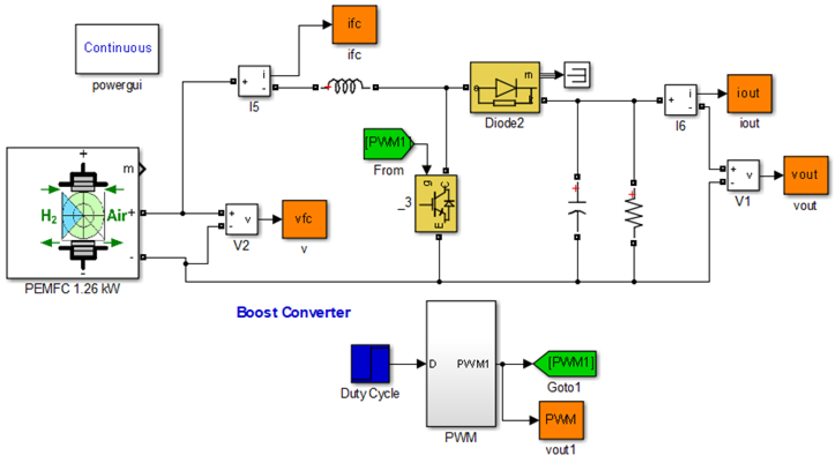
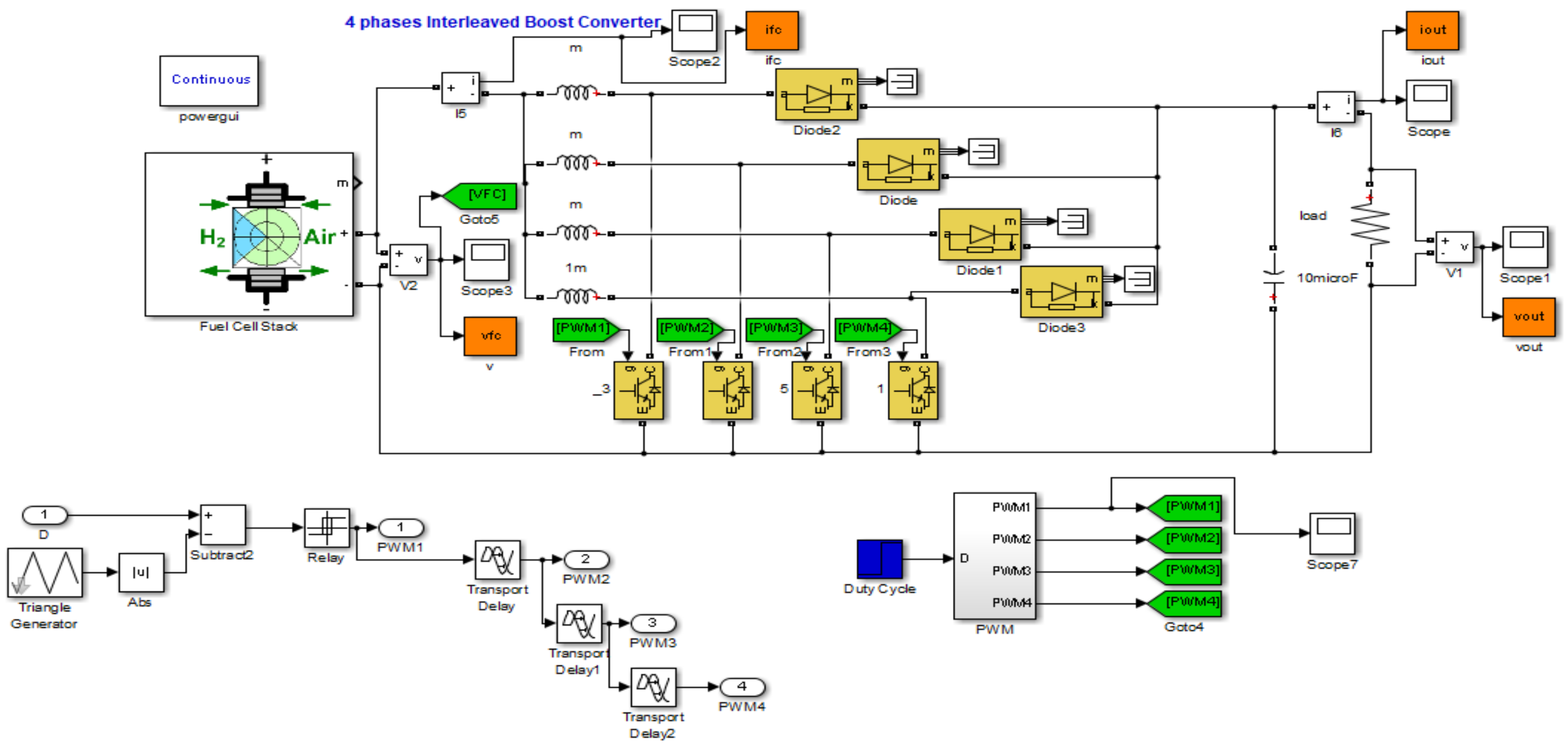
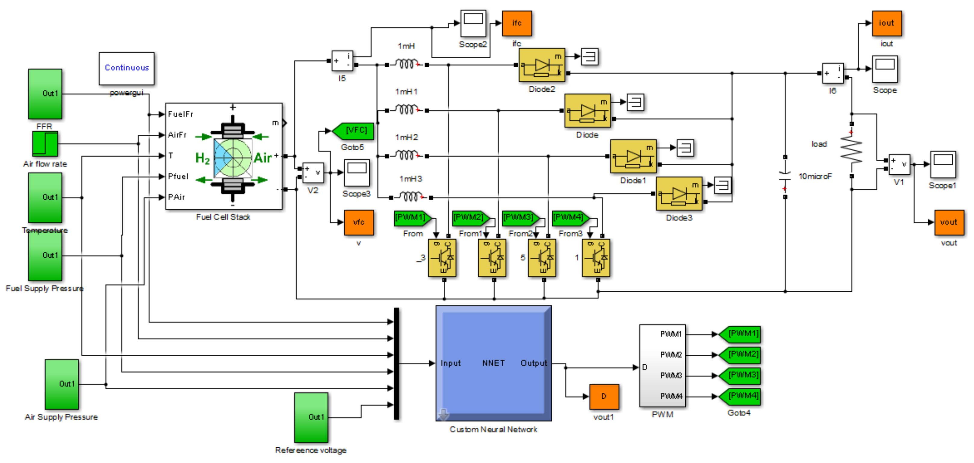
3. Interleaved Boost Converter
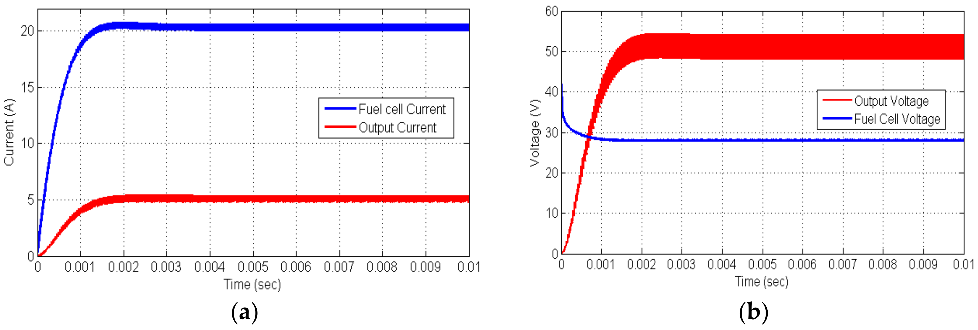
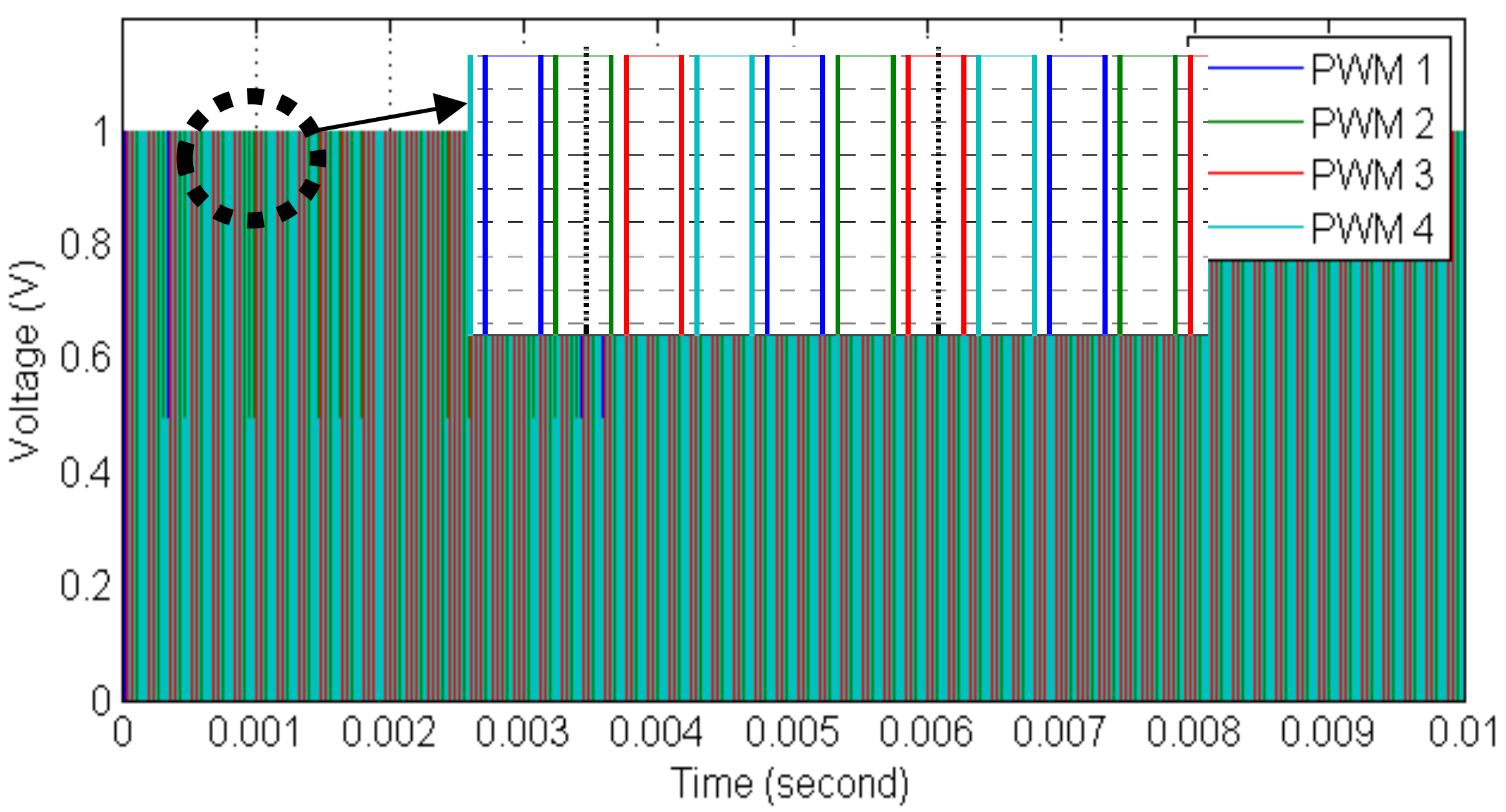
Simulation of the Four Phases Interleaved Boost Converter
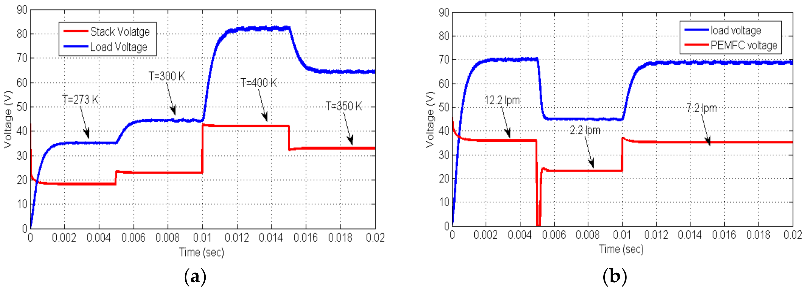
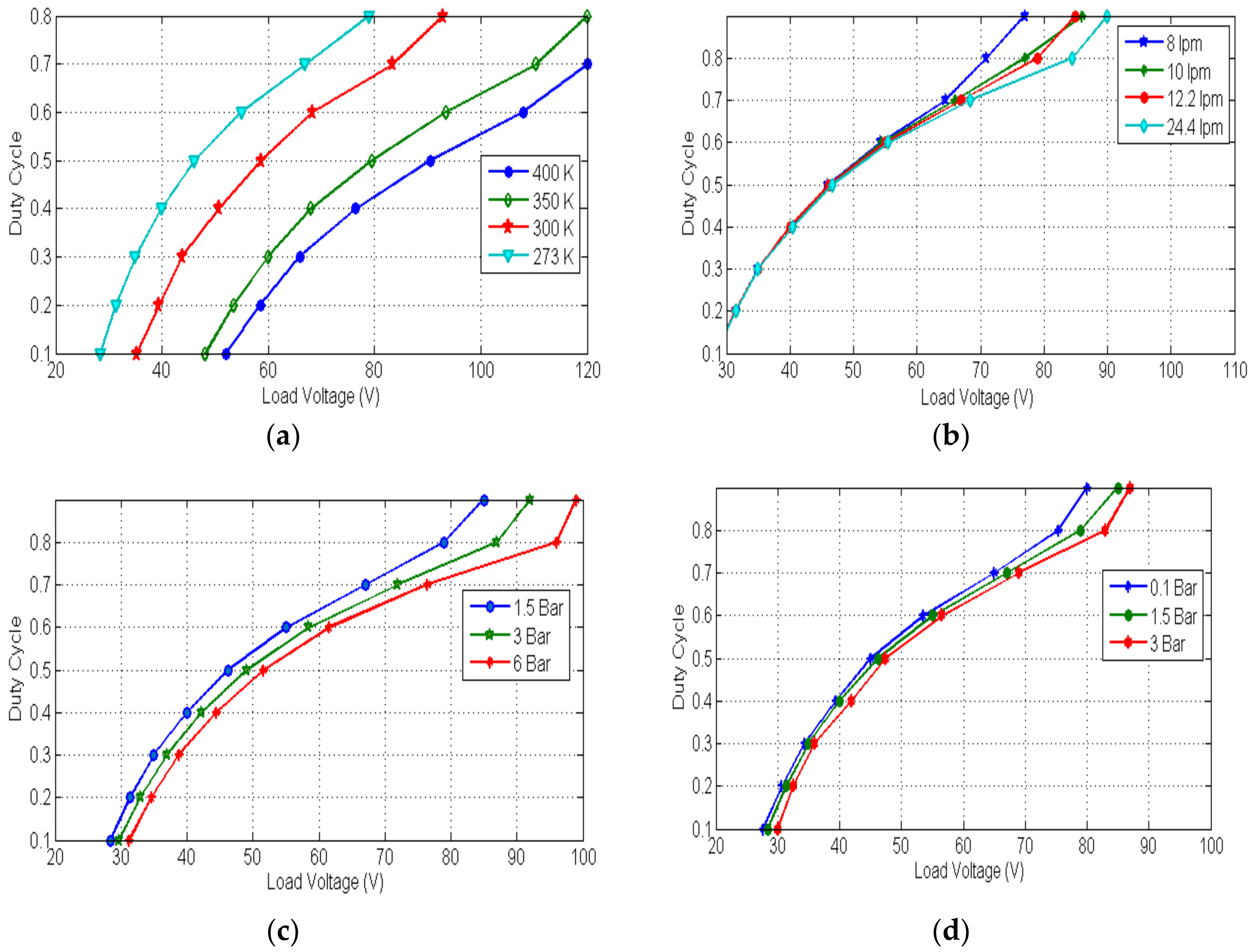
4. Impact of External Parameters on the Output Voltage
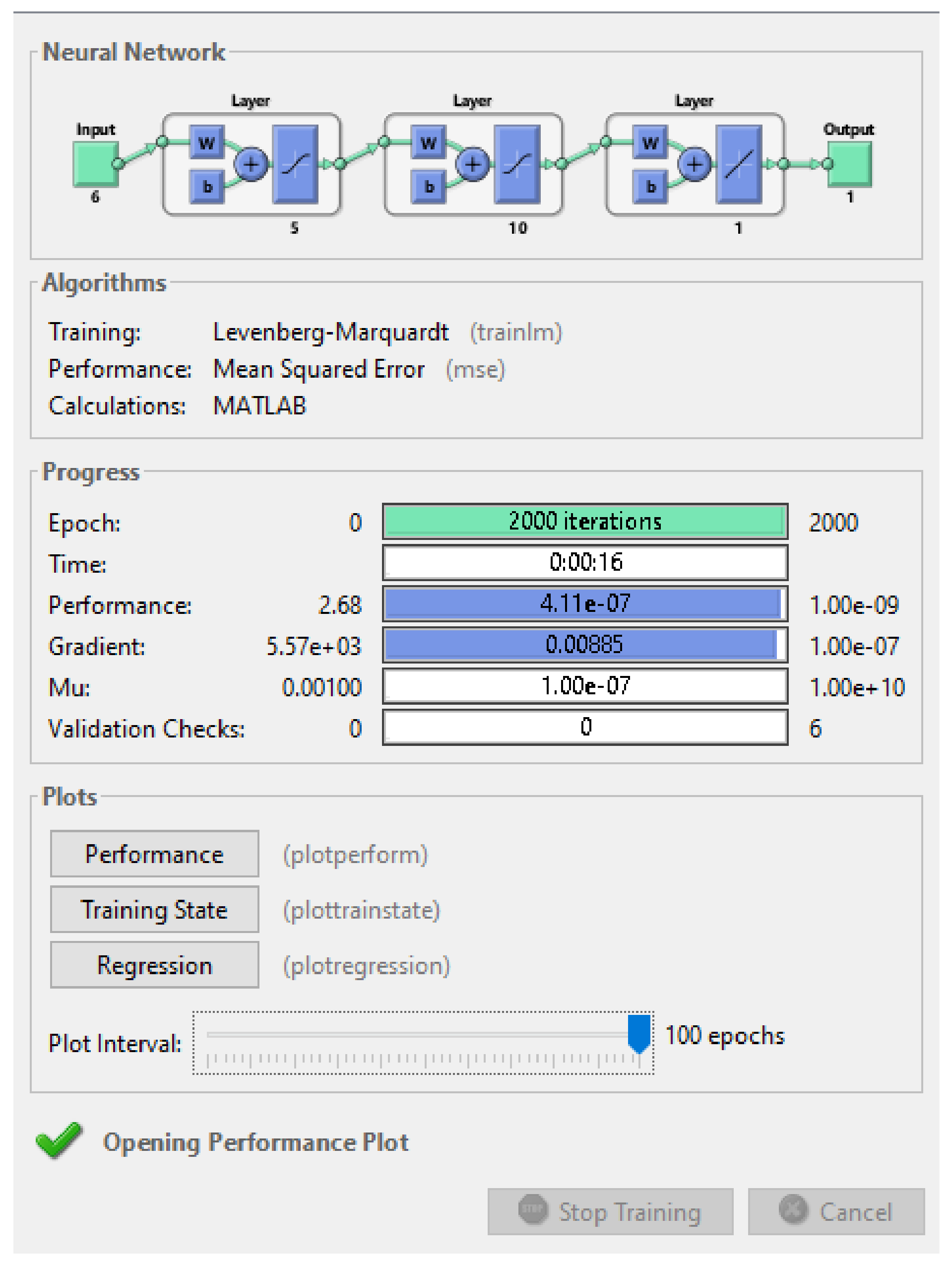
5. Neural Network Regulation
6. Implementation of the Neural Network Controller
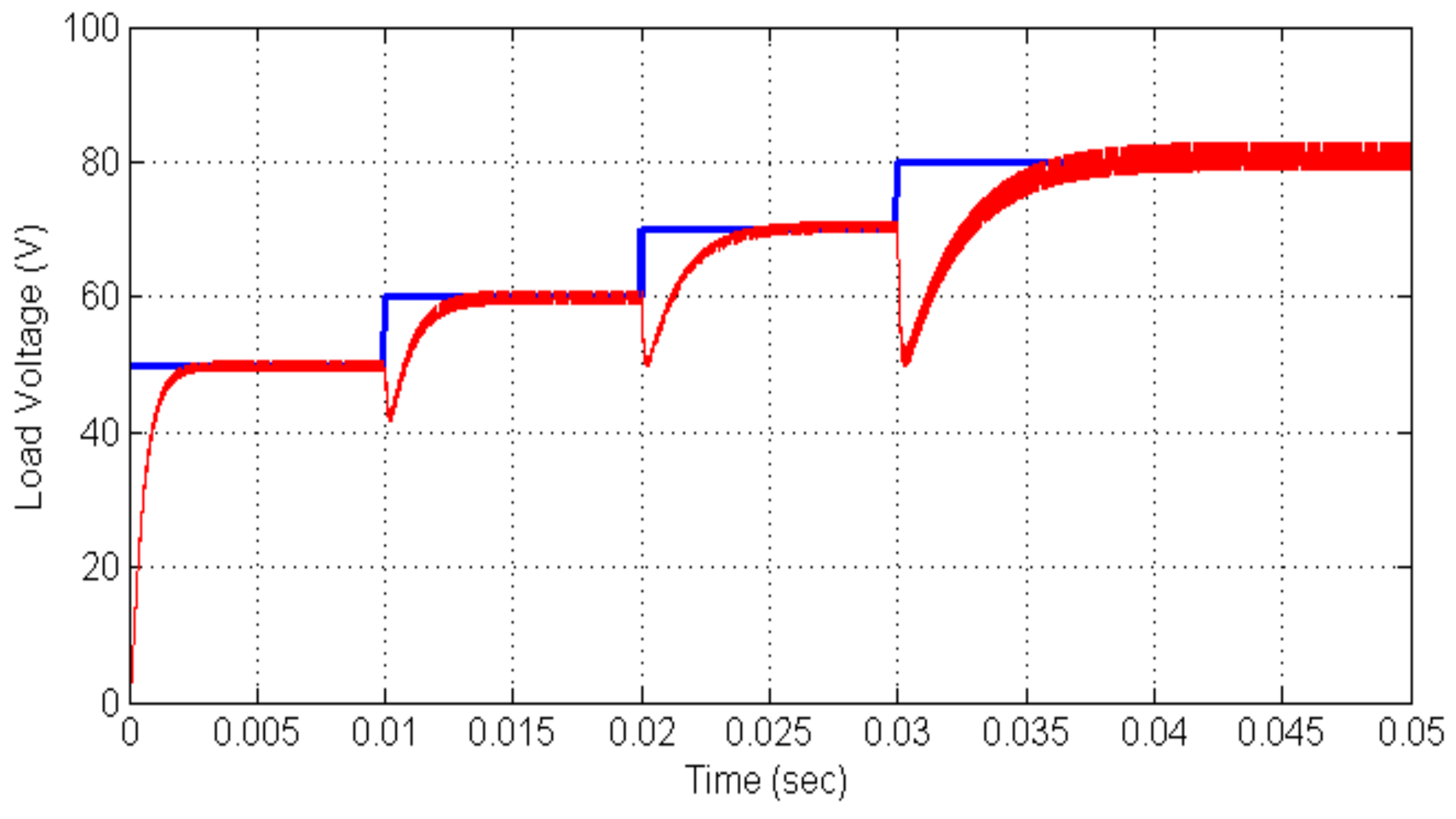
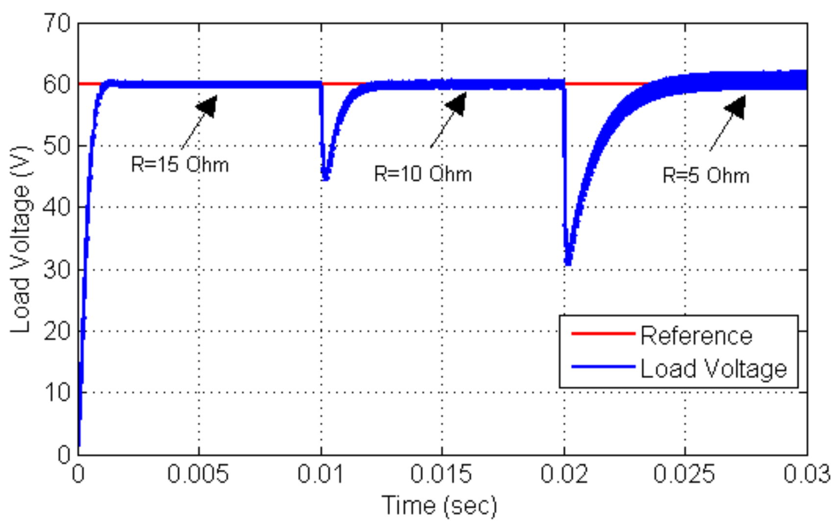
6.1. Effect of the Load Impedance Variation
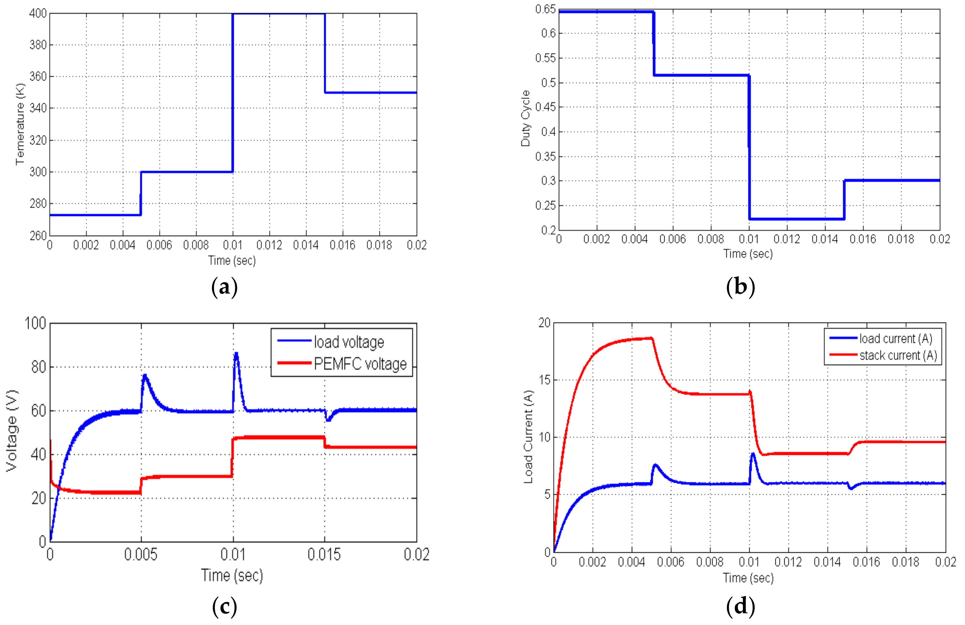
6.2. Effect of the Temperature Variation
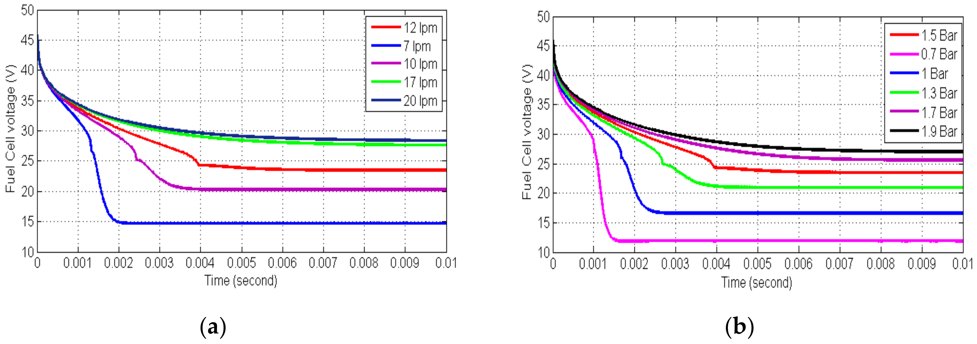
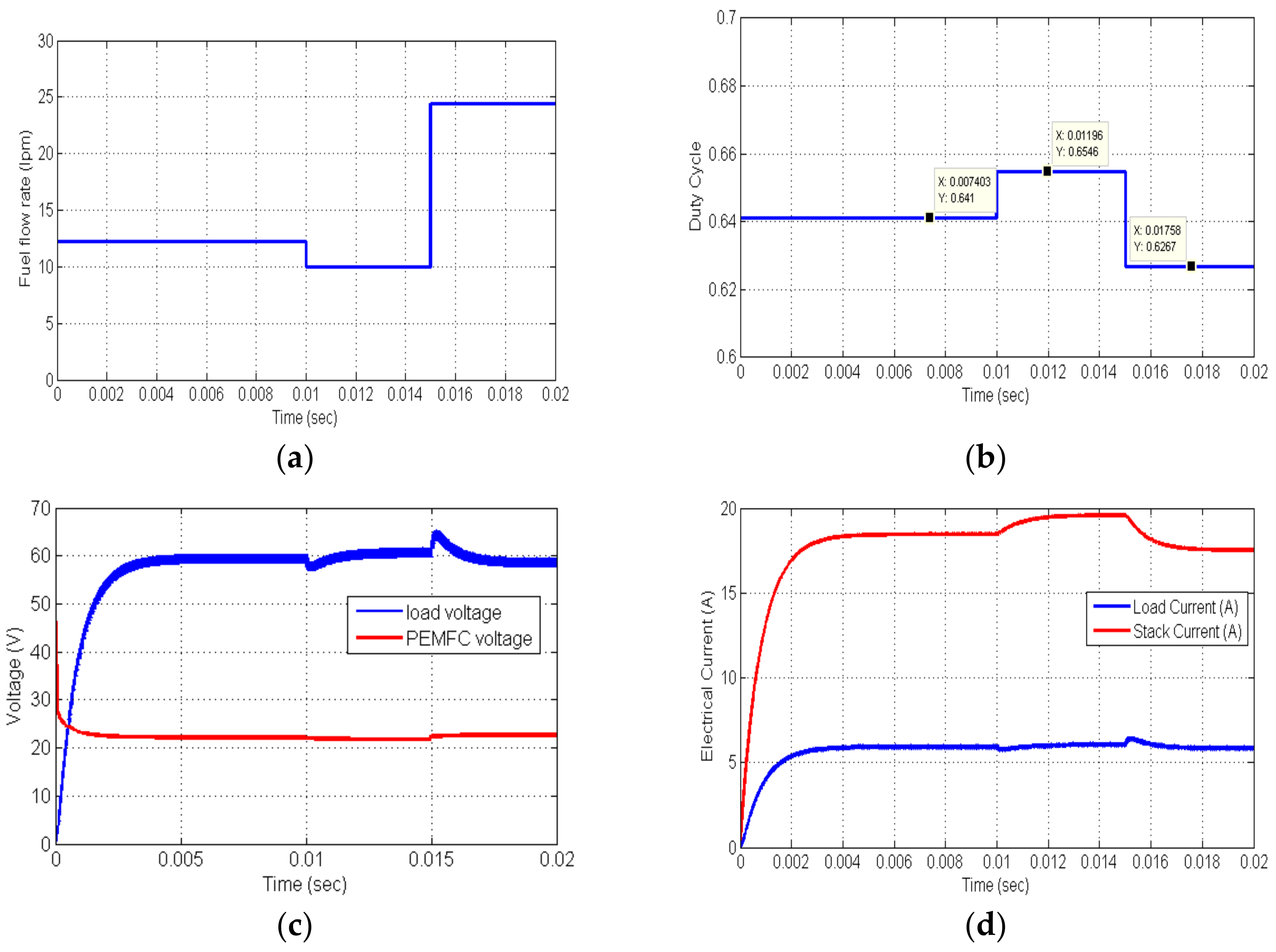
6.3. Effect of the Fuel Flow Rate
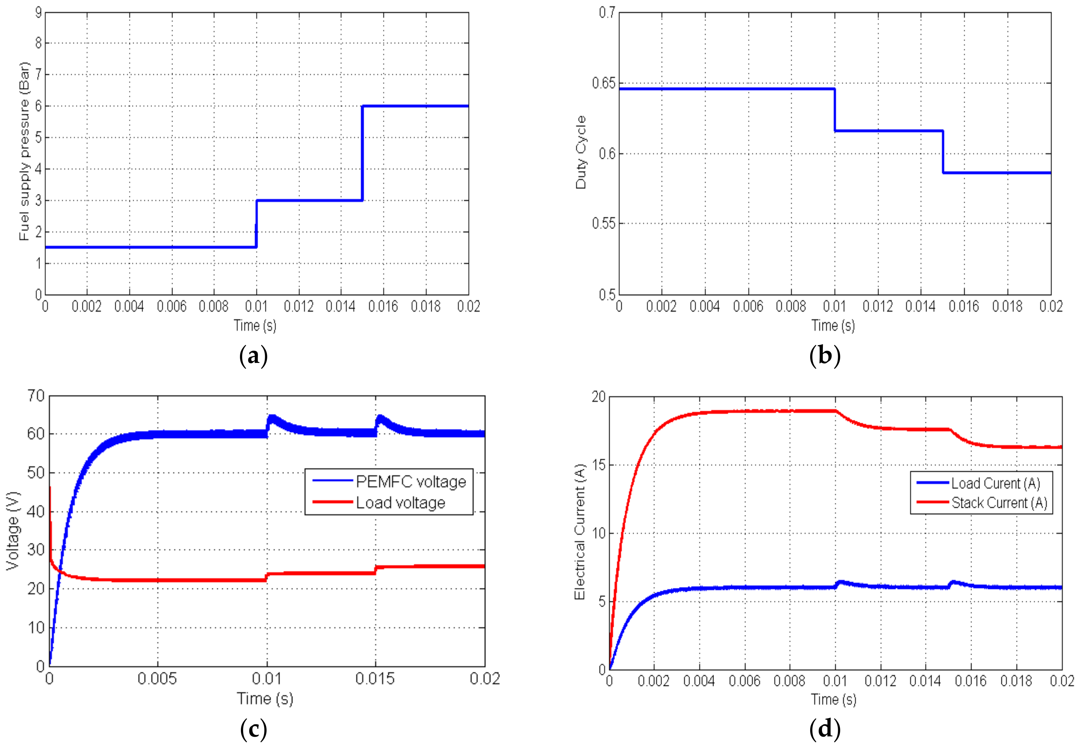
6.4. Variation of the Fuel Supply Pressure
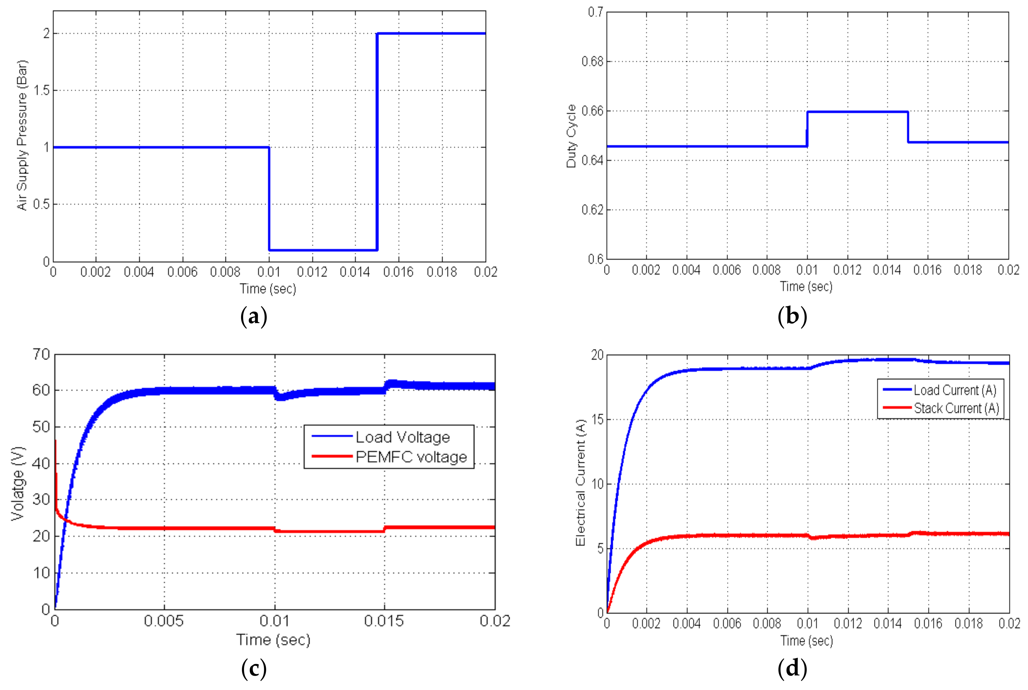
6.5. Variation of the Air Supply Pressure
7. Conclusions
Author Contributions
Funding
Conflicts of Interest
References
- Mann, R.F.; Amphlett, J.C.; Hooper, M.A.I.; Jensen, H.M.; Peppley, B.A.; Roberge, P.R. Development and application of a generalised steady-state electrochemical model for a PEM fuel cell. J. Power Sources 2000, 86, 173–180. [Google Scholar] [CrossRef]
- Correa, J.M.; Farret, F.A.; Canha, L.N.; Simoes, M.G. An electrochemical-based fuel-cell model suitable for electrical engineering automation approach. IEEE Trans. Ind. Electron. 2004, 51, 1103–1112. [Google Scholar] [CrossRef]
- Jin, K.; Ruan, X.; Yang, M.; Xu, M. A hybrid fuel cell power system. IEEE Trans. Ind. Electron. 2009, 56, 1212–1222. [Google Scholar] [CrossRef]
- Khiareddine, A.; Salah, C.B.; Rekioua, D.; Mimouni, M.F. Sizing methodology for hybrid photovoltaic/wind/hydrogen/battery integrated to energy management strategy for pumping system. Energy 2018, 153, 743–762. [Google Scholar] [CrossRef]
- Fuel Cell Electric Vehicles, Reports Fuel Cell Today. Available online: http://www.fuelcelltoday.com (accessed on 15 September 2018).
- Hart, D.W. Power Electronics; Mc Graw Hill: New York, NY, USA, 2010; ISSN 978-0-07-338067. [Google Scholar]
- Rabello, A.L.; Co, M.A.; Simonetti, D.S.L.; Vieira, J.L.F. An isolated DC–DC boost converter using two cascade control loops. In Proceedings of the IEEE International Symposium on Industrial Electronics, Guimaraes, Portugal, 7–11 July 1997; Volume 2, pp. 452–456. [Google Scholar]
- Sundar, G.; Karthick, N.; Reddy, S.R. High step-up DC–DC converter for ac photovoltaic module with MPPT control. J. Electr. Eng. 2014, 65, 248–253. [Google Scholar] [CrossRef]
- Hegazy, O.; van Mierlo, J.; Lataire, P. Analysis, Modeling, and Implementation of a Multidevice Interleaved DC/DC Converter for Fuel Cell Hybrid Electric Vehicles. IEEE Trans. Power Electron. 2012, 27, 2237–2245. [Google Scholar] [CrossRef]
- Lee, S.; Park, J.; Choi, S. A three-phase current-fed push–pull DC–DC converter with active clamp for fuel cell applications. IEEE Trans. Power Electron. 2011, 26, 2266–2277. [Google Scholar] [CrossRef]
- Lim, T.C.; Williams, B.W.; Finney, S.J.; Zhang, H.B.; Croser, C. Energy recovery snubber circuit for a dc-dc push–pull converter. IET Trans. Power Electron. 2012, 5, 863–872. [Google Scholar] [CrossRef]
- Whitaker, B.; Martin, D.; Cilio, E. Extending the operational limits of the push-pull converter with SiC devices and an active energy recovery clamp circuit. In Proceedings of the 2015 IEEE Applied Power Electronics Conference and Exposition (APEC), Charlotte, NC, USA, 15–19 March 2015; pp. 2023–2038. [Google Scholar]
- Omkun, S.; Sirisamphanwong, C.; Sukchai, S. A DSP-based interleaved boost DC-DC converter for fuel cell applications. Int. J. Hydrog. Energy 2015, 40, 6391–6404. [Google Scholar] [CrossRef]
- Thounthong, P.; Rael, S.; Davat, B. Behaviour of a PEMFC supplying a low voltage static converter. J. Power Sources 2006, 156, 119–125. [Google Scholar]
- Saha, S.S. Efficient soft-switched boost converter for fuel cell applications. Int. J. Hydrog. Energy 2011, 36, 1710–1719. [Google Scholar] [CrossRef]
- Giaouris, D.; Stergiopoulos, F.; Ziogou, C.; Ipsakis, D.; Banerjee, S.; Zahawi, B.; Pickert, V.; Voutetakis, S.; Papadopoulou, S. Nonlinear stability analysis and a new design methodology for a PEM fuel cell fed DC-DC boost converter. Int. J. Hydrog. Energy 2012, 37, 18205–18215. [Google Scholar] [CrossRef]
- Hinaje, M.; Sadli, I.; Martin, J.P.; Thounthong, P.; Rafel, S.; Davat, B. Online humidification diagnosis of a PEMFC using a static DC-DC converter. Int. J. Hydrog. Energy 2009, 34, 2718–2723. [Google Scholar] [CrossRef]
- Kirculies, M. Fuel cell power for maritime applications. Fuel Cells Bull. 2005, 2005, 12–15. [Google Scholar]
- Thounthong, P.; Davat, B.; Rae, S.; Sethakul, P. Fuel Cell high power applications. IEEE Trans. Ind. Electron. Mag. 2009, 3, 32–46. [Google Scholar]
- Bizon, N. Effective mitigation of the load pulses by controlling the battery/SMES hybrid energy storage system. Appl. Energy 2018, 229, 459–473. [Google Scholar] [CrossRef]
- Lu, N.; Yang, S.; Tang, Y. Ripple Current Reduction for Fuel-Cell-Powered Single-Phase Uninterruptible Power Supplies. IEEE Trans. Ind. Electron. 2017, 64, 6607–6617. [Google Scholar] [CrossRef]
- Kaouane, M.; Khelifaa, A.B.; Cheritib, A. Regulated output voltage double switch Buck-Boost converter for photovoltaic energy application. Int. J. Hydrog. Energy 2016, 41, 20847–20857. [Google Scholar] [CrossRef]
- Farhani, S.; Amari, M.; Marzougui, H.; Bacha, F. Analysis, modeling and implementation of an interleaved boost DC-DC converter for fuel cell used in electric vehicle. Int. J. Hydrog. Energy 2017, 42, 28852–28864. [Google Scholar] [CrossRef]
- Ou, K.; Yuan, W.-W.; Choi, M.; Yang, S.; Kim, Y.-B. Performance increase for an open-cathode PEM fuel cell with humidity and temperature control. Int. J. Hydrog. Energy 2017, 42, 29852–29862. [Google Scholar] [CrossRef]
- Bizon, N.; Mazare, A.G.; Ionescu, L.M.; Enescu, F.M. Optimization of the Proton Exchange Membrane Fuel Cell Hybrid Power System for Residential Buildings. Energy Convers. Manag. 2018, 163, 22–37. [Google Scholar] [CrossRef]
- Reddy, K.J.; Sudhakar, N. High Voltage Gain Interleaved Boost Converter with Neural Network Based MPPT Controller for Fuel Cell Based Electric Vehicle Applications. IEEE Access 2018, 6, 3899–3908. [Google Scholar] [CrossRef]
- Wang, W.Y.; Ding, Y.H.; Ke, X.; Ma, X. Sliding mode control of direct coupled interleaved boost converter for fuel cell. In IOP Conference Series: Earth and Environmental Science; Conference 1; IOP Publishing: Bristol, UK, 2017; Volume 100. [Google Scholar]
- Barhoumi, E.M.; Ben Salah, B. Modelling and Control of a new Linear Switched Reluctance Motor for Shunting the Railways Channels. Int. Rev. Model. Simul. (IREMOS) 2011, 4, 2012–2019. [Google Scholar]
- Barhoumi, E.M.; Ben Salah, B. New Positioning Control of Stepper Motor using BP Neural Networks. J. Emerg. Trends Comput. Inf. Sci. 2011, 2, 300–306. [Google Scholar]
- Barhoumi, E.M.; Ben Salah, B. Design and Simulation of a new Linear Switched Reluctance Motor for Shunting the Railways Channels. Int. Rev. Model. Simul. (IREMOS) 2011, 3, 1072–1078. [Google Scholar]


| Parameter | Value |
|---|---|
| Stack rating voltage (V) | 24 |
| Power (kW) | 1.26 |
| Stack rating Current (A) | 52 |
| Maximum Current (A) | 100 |
| Maximum voltage (V) | 42 |
| Number of Cells | 42 |
| Nominal stack Efficiency | 46% |
| Time constant | 1 ms |
| Parameter | Symbol | Value |
|---|---|---|
| Inductance (mH) | L | 1 |
| Capacitance () | C | 50 |
| Input Voltage (V) | VStack | --- |
| Load resistance () | R | 10 |
| Duty Cycle | D | 0.5 |
| Frequency (kHz) | f | 25 |
| Type of Control | DC Link Voltage | Fuel Cell Current Ripple |
|---|---|---|
| Multidevice Interleaved DC/DC Converter for Fuel Cell Hybrid Electric Vehicles [9] | 400 V | 0.7 A |
| Maximum Power Point Technique [26] | 220 V | 0.1 A |
| Sliding mode control [27] | 100 V | 0.3 A |
| Proposed ANN controller for the IBC | 60 V | 0.01 A |
| Type of Control | Load Voltage Regulation in the Presence of the Variation of | |||||
|---|---|---|---|---|---|---|
| Load Impedance | Temperature | Hydrogen Pressure | Hydrogen Flow Rate | Air Pressure | Air Flow Rate | |
| Controlling the SMES hybrid energy storage system [20] | P | NP | NP | NP | NP | NP |
| Proportional Integral Controller [23] | P | NP | NP | NP | NP | NP |
| Optimization of the PEMFC Hybrid System [25] | P | NP | NP | P | NP | P |
| Maximum Power Point Technique [26] | P | P | NP | NP | NP | NP |
| Sliding mode control [27] | P | NP | NP | NP | NP | NP |
| Proposed ANN controller | P | P | P | P | P | P |
© 2018 by the authors. Licensee MDPI, Basel, Switzerland. This article is an open access article distributed under the terms and conditions of the Creative Commons Attribution (CC BY) license (http://creativecommons.org/licenses/by/4.0/).
Share and Cite
Barhoumi, E.M.; Ben Belgacem, I.; Khiareddine, A.; Zghaibeh, M.; Tlili, I. A Neural Network-Based Four Phases Interleaved Boost Converter for Fuel Cell System Applications. Energies 2018, 11, 3423. https://doi.org/10.3390/en11123423
Barhoumi EM, Ben Belgacem I, Khiareddine A, Zghaibeh M, Tlili I. A Neural Network-Based Four Phases Interleaved Boost Converter for Fuel Cell System Applications. Energies. 2018; 11(12):3423. https://doi.org/10.3390/en11123423
Chicago/Turabian StyleBarhoumi, El Manaa, Ikram Ben Belgacem, Abla Khiareddine, Manaf Zghaibeh, and Iskander Tlili. 2018. "A Neural Network-Based Four Phases Interleaved Boost Converter for Fuel Cell System Applications" Energies 11, no. 12: 3423. https://doi.org/10.3390/en11123423
APA StyleBarhoumi, E. M., Ben Belgacem, I., Khiareddine, A., Zghaibeh, M., & Tlili, I. (2018). A Neural Network-Based Four Phases Interleaved Boost Converter for Fuel Cell System Applications. Energies, 11(12), 3423. https://doi.org/10.3390/en11123423