Article

Study of the Intelligent Behavior of a Maximum Photovoltaic Energy Tracking Fuzzy Controller

by
Gul Filiz Tchoketch Kebir
1,2,*,
Cherif Larbes
2,
Adrian Ilinca
1,
Thameur Obeidi
1,2 and
Selma Tchoketch Kebir
2
1
Wind Energy Research Laboratory, Université du Québec à Rimouski, 300, Allée des Ursulines, Rimouski, QC G5L 3A1, Canada
2
Laboratoire des Dispositifs de Communication et de Conversion Photovoltaïque, Département d’Électronique, École Nationale Polytechnique, 10, Avenue Hassen Badi, El Harrach, Alger 16200, Algerie
*
Author to whom correspondence should be addressed.
Energies 2018, 11(12), 3263; https://doi.org/10.3390/en11123263
Submission received: 16 October 2018 / Revised: 16 November 2018 / Accepted: 17 November 2018 / Published: 23 November 2018
(This article belongs to the Special Issue Intelligent Control in Energy Systems)

Abstract

:
The Maximum Power Point Tracking (MPPT) strategy is commonly used to maximize the produced power from photovoltaic generators. In this paper, we proposed a control method with a fuzzy logic approach that offers significantly high performance to get a maximum power output tracking, which entails a maximum speed of power achievement, a good stability, and a high robustness. We use a fuzzy controller, which is based on a special choice of a combination of inputs and outputs. The choice of inputs and outputs, as well as fuzzy rules, was based on the principles of mathematical analysis of the derived functions (slope) for the purpose of finding the optimum. Also, we have proved that we can achieve the best results and answers from the system photovoltaic (PV) with the simplest fuzzy model possible by using only 3 sets of linguistic variables to decompose the membership functions of the inputs and outputs of the fuzzy controller. We compare this powerful controller with conventional perturb and observe (P&O) controllers. Then, we make use of a Matlab-Simulink® model to simulate the behavior of the PV generator and power converter, voltage, and current, using both the P&O and our fuzzy logic-based controller. Relative performances are analyzed and compared under different scenarios for fixed or varied climatic conditions.

1. Introduction

Solar energy conversion using photovoltaic (PV) generators has lately been in accelerated development, both for small and large installations. This clean, quiet and low-maintenance energy source has seen the largest growth rate with a renewable and continuous price reduction. Its further development requires improvement of conversion efficiency and component cost reduction. The electrical energy extracted by the photovoltaic generators depends on a complex equation relating the solar radiation, the temperature, and the total resistance of the circuit, which results in a nonlinear variation of the output power P as a function of the circuit voltage V in the form P = f(V) [1,2]. There is a unique point, under given irradiation and temperature conditions, where the generator produces maximum power, named the MPP (maximum power point). This MPP is reached when the power’s rate of change as a function of voltage is equal to zero. The nonlinear relationship of the power output from the PV generator with respect to environmental conditions renders the conversion efficiency of solar generators relatively low, so power extraction optimization becomes a key issue in solar energy conversion [3,4]. This paper focuses on the development of a coupled fuzzy logic–mathematical analysis method as a maximum power point tracking (MPPT) technique to increase the power extracted by the PV generator.

2. Motivation

In the case of considering photovoltaic power output with respect to voltage for a particular solar generator under varying irradiation and temperature levels, we note that there is a unique point where maximum power can be harvested (Figure 1) [2,4].
A similar MPP tracking analysis can be performed by considering an I-V curve, as shown in Figure 2 below. If we consider irradiation S, a temperature T, and a varying resistive load Ri, then the solar cell provides a short-circuit current ISC and an open circuit voltage VOC. We note that there exists an MPP that can be identified from the I-V curve. Whatever the approach, P-V or I-V, the tracking of gradient variation of I or V enables us to identify the maximum power point from a PV generator [1,3]. In the literature [2], there are a number of MPPT (Maximum Power Point Tracking) techniques used to optimize the efficiency of photovoltaic systems.
Photovoltaic systems are generally connected to static converters (DC-DC) driven by programmed controllers that continuously analyze the power output from the solar generator. MPPT controllers adjust the parameters to extract maximum energy, whatever the load and atmospheric conditions are [5]. The MPPT methods portrayed in the different studies use different techniques and algorithms which widely differ in performance, such as convergence speed, implementation complexity, accuracy, and most importantly, the cost of implementation of the whole setup [6]. In the following paragraphs, we briefly recall the principles of some of the most popular MPPT tracking algorithms.
The “Hill Climbing/P&O Method” [7,8,9,10]: The principle of this algorithm is to calculate the power provided by the PV panel at time k, following a disturbance effect on the voltage of the PV panel while acting on the duty cycle, D. This is compared to the previous measurement at the moment k−1. If the power increases, we approach the MPP, and the variation of the duty cycle is maintained in the same direction. On the contrary, if the power decreases, we move away from the MPP. So, we have to reverse the direction of the change in the duty cycle.
The “Incremental Conductance Method” [11,12]: The principle of this algorithm is based on the knowledge of the value of the conductance G = I/V on the increment of the conductance dG to deduce the position of the operating point relative to the MPP. If dG is greater than the opposite of the conductance −G, the duty cycle is decreased. On the other hand, if dG is lower than −G, the duty cycle is increased. This process is repeated until reaching the MPP.
The “Fractional Open-Circuit Voltage Method” [2,4]: This method is based on the relation VMPP = α × VOC, where α is a voltage factor depending on the characteristics of the PV cell. To deduce the optimal voltage, the VOC voltage must be measured. As a result, the operating point of the panel is kept close to the MPP by adjusting the panel voltage to the calculated optimal voltage. This is achieved by cyclically acting on the duty cycle to reach the optimum voltage.
The “Fractional Short-Circuit Current Method” [6,13]: This technique is based on the relation IMPP = α × ISC, where α is a current factor depending on the characteristics of the PV cell. The optimum operating point is obtained by bringing the current of the panel to the optimum current, changing the duty cycle until the panel reaches the optimum value.
Algorithms based on fuzzy logic [3,14,15,16]: MPPT control techniques based on fuzzy logic have recently been introduced because they offer the advantage of robust control and do not require exact knowledge of the mathematical model of the system. In addition, they improve performances (convergence speed, accuracy, ease of implementation, and low cost).
Other MPPT techniques include the “Artificial Intelligence Algorithms” [10,17]. These new technology MPPT algorithms are inspired by nature and biological structures. Among them we can mention the “particle-swarm-optimisation-based MPPT” [5,18], “genetic algorithms“ [19], “neural networks“ [12,20], and the “hybrid methods” [5,21].
According to the literature [4,22,23,24], we used a comparative study in Table 1 between the most used methods in terms of technical knowledge of PV panel parameters, complexity, speed, and accuracy.
This paper is organized as follows: Section 3 is reserved for the study of the photovoltaic system, starting with a presentation of the photovoltaic panel. Next we explain all the parts constituting the architecture and the functioning of a PV-MPPT system. To improve the MPPT techniques’ relative performances (convergence speed, accuracy, ease of implementation, and low cost), we have developed a control method using fuzzy logic that has been applied to a step-up boost MPPT for PV generators in Section 4. In Section 5, we talk about the most popular conventional MPPT controller based on the P&O algorithm. These techniques are studied and analyzed both theoretically and by simulation using Matlab-Simulink® (R2018a, Mathworks, Natick, MA, USA) in Section 6. Then, a comparison is presented of the performance of both methods.

3. Challenges in Exploiting the Maximum Energy from the Photovoltaic System

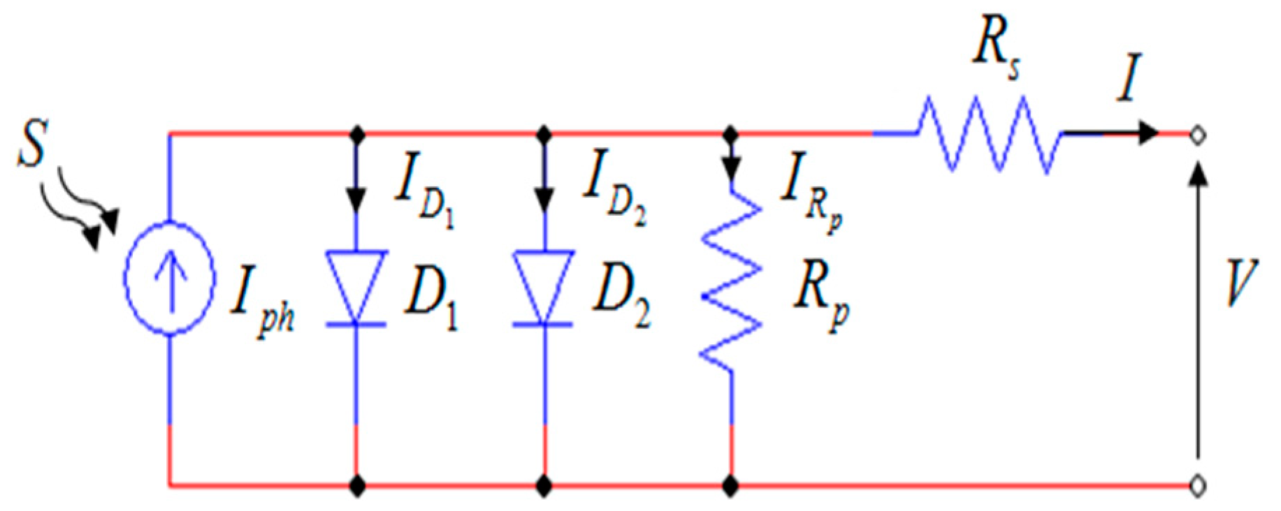
Our analysis is performed on the most sophisticated and widespread real photovoltaic cell model, consisting of two-diodes [1,25] as illustrated in Figure 3:
Equation (1) expresses the mathematical relationship of the circuit output current in terms of the circuit parameters [25]:
I = S I p h ( T ) I s 1 [ e q ( V + I R s ) n 1 k T 1 ] I s 2 [ e q ( V + I R s ) n 2 k T 1 ] V + I R s R P  
where:
I p h ( T ) = I p h | ( T = 298 K ) [ 1 + ( T 298 ) ( 5 10 4 ) ]  
I s 1 = K 1 T 3 e E g k T  
I s 2 = K 2 T 5 2 e E g k T  
I and V are the output current and output voltage of the photovoltaic cell, S is the irradiance, T is the absolute temperature in Kelvin, Iph(T) is the generated photo-current, Is1 and Is2 are the diode saturation currents and the reverse diode saturation currents, n1 and n2 are the diode ideality factors, Rs the series resistance, and Rp the parallel resistance. Eg is the band-gap energy of the semiconductor, q is the elementary charge constant (1.602 × 10⁻¹⁹ C) and k is the Boltzmann constant (1.38 × 10⁻²³ J/K), K1 = 1.2 A/cm2K3 and K2 = 2.9 × 10⁵ A/cm2K5/2.
Equation (1) leads to a generalized equation of the entire photovoltaic panel with z photovoltaic cells, connected in series [1,25]:
I = S I p h ( T ) I s 1 [ e q ( V + I z R s ) z n 1 k T 1 ] I s 2 [ e q ( V + I z R s ) z n 2 k T 1 ] V + I z R s z R p  
From Equation (5), we note that the output current of a photovoltaic panel connected to a load Ri is highly dependent on the I-V variation of this load (Figure 2). Furthermore, Equation (5) illustrates that the I-V and P-V characteristics of the PV module vary not only with the connected load, but also with temperature and solar irradiance. Therefore, for each temperature and irradiance condition, it is necessary to track the corresponding MPP. Figure 1 illustrates the existence of an MPP on the P-V characteristic of PV generator, with variable irradiance and temperature according to Equation (5).
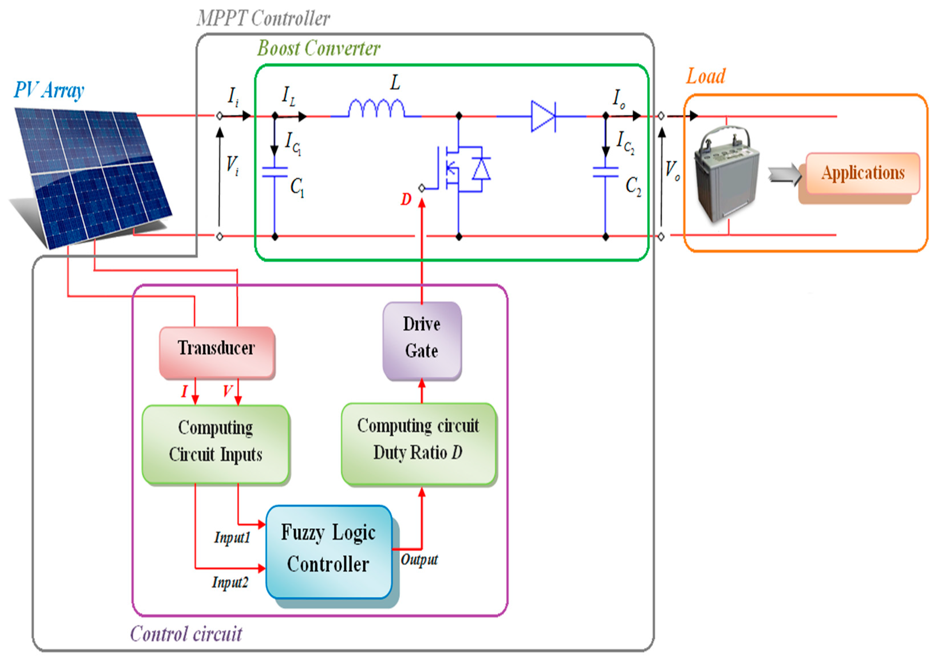
To force the PV system to operate in its MPP region according to incident irradiation and temperature, it is necessary to include a maximum power point tracking (MPPT) device between the PV module and the load (Figure 4). The MPPT device consists of a DC-DC converter which can be buck-type, boost-type, or buck-boost type [23,26]. The step-up boost converter has been chosen in this work.
The transducer captures the instantaneous values of current I and voltage V from the PV array, Which are used by the computing circuit inputs for the calculation of the inputs of the fuzzy logic controller. The control output must be injected into another circuit of calculation to determine the duty ratio D, which will be used at the end of the process by the drive gate to control directly the Mosfet of the boost converter (Figure 4).
The DC-DC converter is included between the array of photovoltaic cells and the energy storage unit (load) to match the voltage of the solar array with the battery voltage. If the duty ratio D of the converter is varied by a control circuit to constantly adjust the operating voltage of the solar panel to its point of maximum power VMPP, that means it is operated as a maximum power point tracker MPPT (Figure 5).
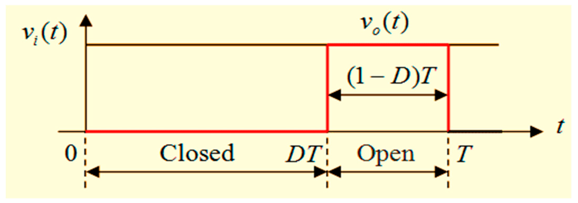
The DC-DC switching converter consists of capacitors, inductors, and switches. Ideally, the power consumption of all these devices is very low, which is the reason for the efficiency of DC-DC switching converters [25,27]. A metal oxide semiconductor field effect transistor (MOSFET) is used as a switching semiconductor device since it is easy to control using a pulse width modulation (PWM) signal generated by the controller. During the operation of the converter, the switch will be geared at a constant frequency f with an on-time value DT and an off-time value (1 − D)T, where T is the switching period and D is the duty ratio of the switch ( D ]0,1[) (Figure 6).
Figure 7 illustrates the step-up boost converter circuit used in the MPPT technique.
Mathematical equations of the step-up Boost converter used in the Matlab-Simulink model are as follows:
V o V i = 1 ( 1 D )  
I L = I i C 1 d V i d t  
I o = ( 1 D ) I L C 2 d V o d t  
V i = ( 1 D ) V o + L d I L d t  
It is understood from Equation (6) that an increase in duty ratio results in an increase of the output voltage of the boost converter, and vice-versa. Hence, MPPT device instantly controls the decrease and increase of the duty ratio D in order to push the operating point to the MPP (Figure 5).

4. The Fuzzy Logic MPPT-Based Controller

4.1. Methodology

The mathematical study of the P-V characteristic illustrated in Figure 5 leads us to the choice of the following MPPT algorithm:
(1)
The analysis of the slope m(pi) at the pi point on the P-V characteristic (Figure 5) is used to locate the actual operation point pi. According to this data, the controller will decide whether to increase or decrease the voltage by varying the duty ratio D.
(2)
Analysis of the rate of change of the slope at the pi point Δm(pi) = s(pi) expresses the rate of the approach and distancing of the MPP. This parameter is also included in the controller for faster MPP searching.

4.2. The Configuration of the Fuzzy Controller

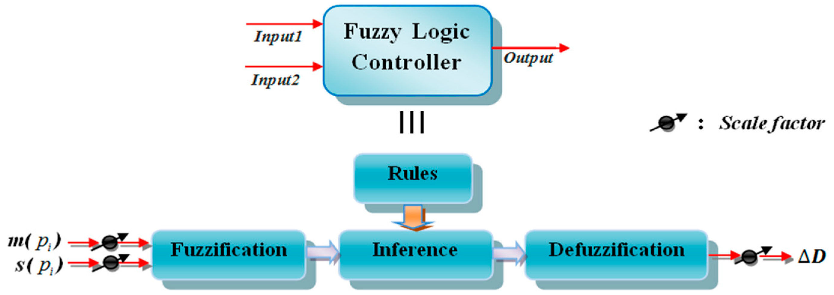
Fuzzy systems are good models for nonlinear systems. Fuzzy models are based on fuzzy rules. These fuzzy rules provide information about uncertain nonlinear systems [28]. A fuzzy logic controller consists of three main operations: “Fuzzification”, “inferencing”, and “defuzzification” [29,30]. The input data are fed into a fuzzy logic-based system where physical quantities are represented as linguistic variables with appropriate membership functions. These linguistic variables are then used in the antecedents (If-Part) of a set of fuzzy “If-Then” rules within an inference engine to result in a new set of fuzzy linguistic variables, or a consequent (Then-Part) [31]. Figure 8 illustrates the schematic representation of the fuzzy controller:

4.2.1. Fuzzification

The control circuit instantaneously measures the voltage V(i) and current I(i) of the photovoltaic generator and calculates power as P(i) = I(i) × V(i). As explained in Section 4.1, the controller analyses input1(i) that represents the slope of the current operating point on the P-V curve (m(pi)) and input2(i) that represents the rate of approaching or distancing of the point pi toward MPP. The fuzzy controller takes instantaneous measurements of these two input values and then decides and calculates the output, Δ D ( i ) which is actually the change of the duty ratio of the MOSFET. The input and output variables of the fuzzy controller are expressed in terms of membership functions. Determination of the range of fuzzy linguistic variables that composes the membership functions of the input and output variables of the fuzzy controller is based on the experiences and observations of automation specialists who works with the PV system [31,32], as well as on the right choice of the rules of inference.
In other words, our observations suggest that the value of the slope of a point pi on the curve in Figure 5 (which represents input1) will be positive, negative, or zero (zero is the MPP). The value of change of the slope of two points pi and pi−1 on the same curve (and which represents input2) will be either positive, negative or zero. The fuzzy controller will decide to increase, decrease, or stabilize the output of the command, which is ΔD.
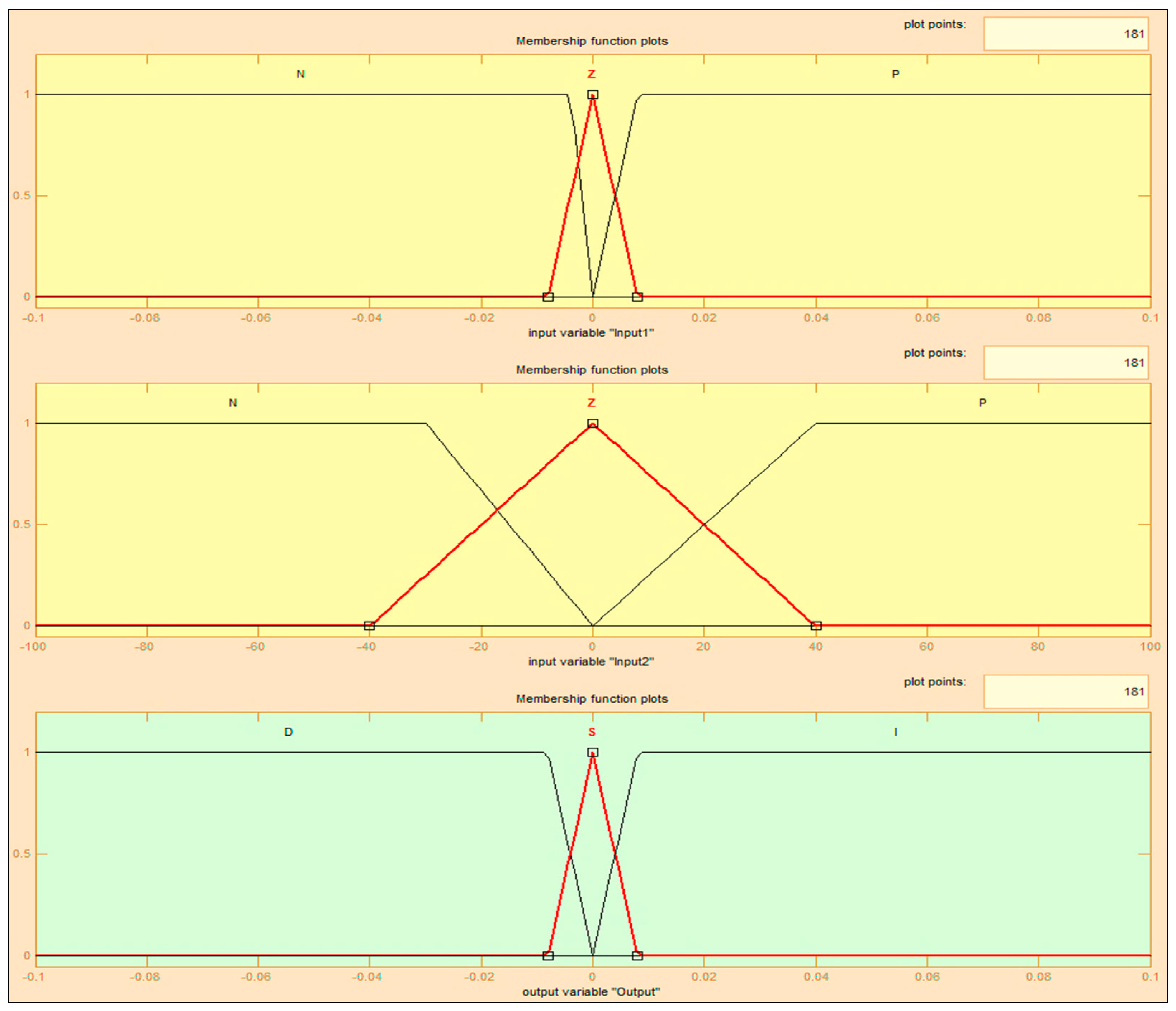
Therefore, in order to achieve the best possible results from our simulations experiments, and after several calculations and tests on our PV system, we decided to choose the decomposition of the following membership functions shown in Figure 9.
We propose to define the membership functions of the inputs and the output in terms of a set of linguistic variables:
(1)
Input1: N: Negative, Z: Zero, P: Positive,
(2)
Input2: N: Negative, Z: Zero, P: Positive,
(3)
Output: D: Decrease, S: Stabilize, I: Increase.
The real values of input1, input2, and the output are normalized by an input scaling factor [32,33]. In this system, the input scaling factor has been designed as follows:
  • Input1 values are between −0.1 and 0.1;
  • Input2 values are between −100 and 100;
  • Output values are between −0.1 and 0.1.
In the literature [31], different forms of membership functions may exist: Trapezoidal, triangular, rectangular, bell-shaped, concave shapes, etc. Triangular or trapezoidal shapes are generally used in this work as membership functions. The choice of the functions is also based on users’ experience. Membership functions need to overlap to enable partial inclusion of the same linguistic variable at the same time in two different fuzzy sets [1,19,31].

4.2.2. The Inference Method

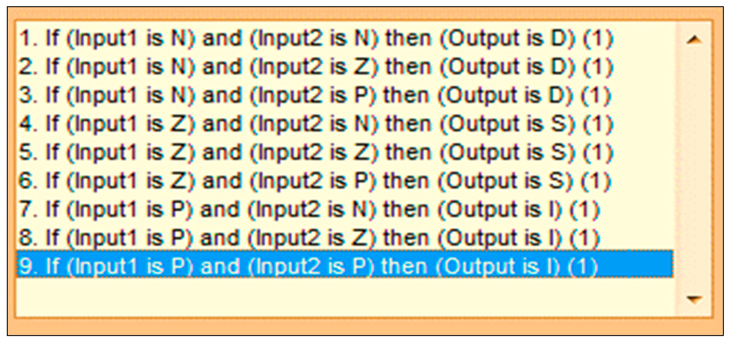
The inference method works in such a way that a change in the duty ratio of the boost chopper leads to the voltage VMPP corresponding to the MPP. Following the analysis of an exhaustive number of combinations of input variables and an analysis of the corresponding outputs, we propose decision inference rules, illustrated in Figure 10:
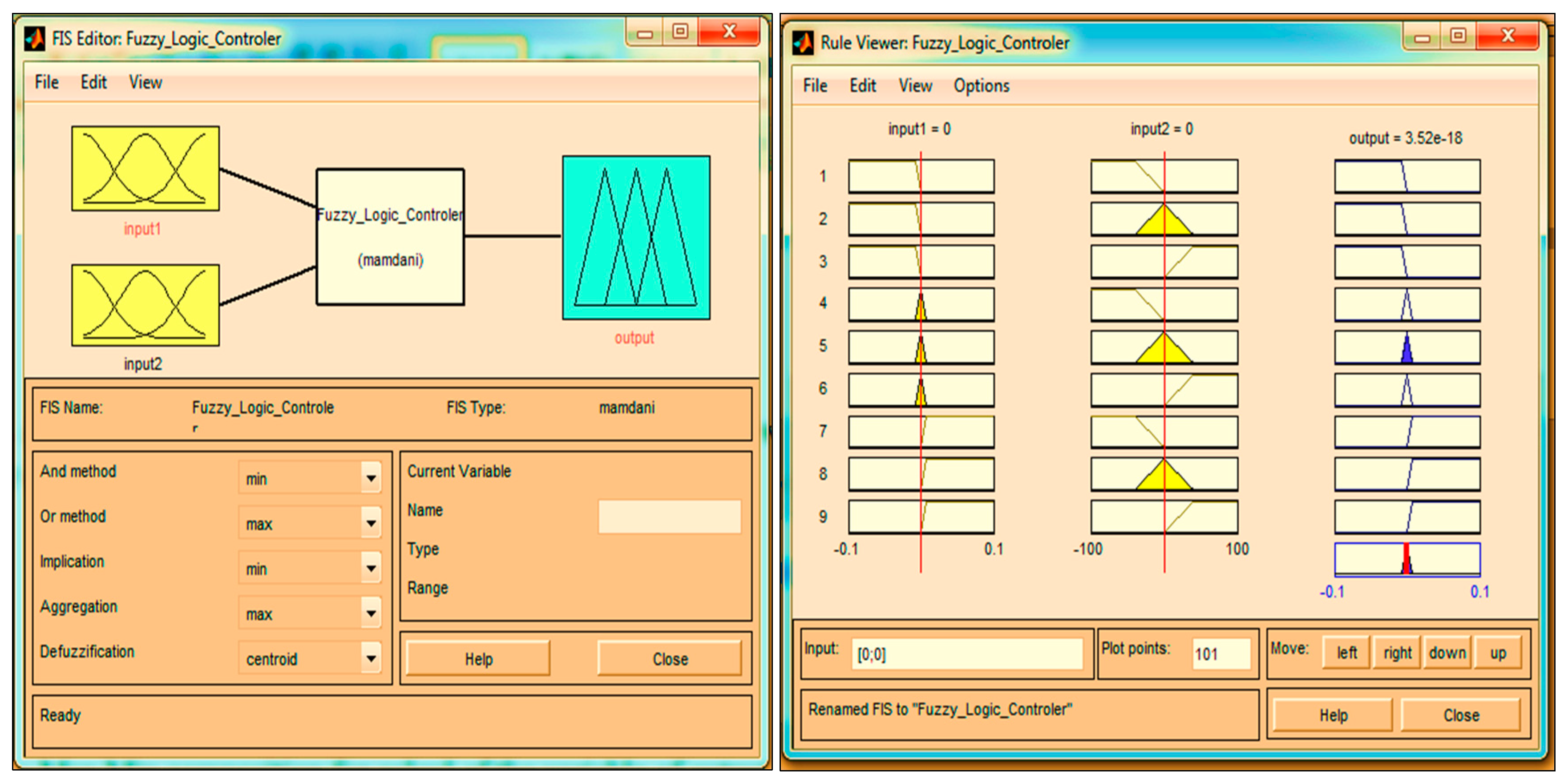
In this work, we have used the Mamdani method [31] for fuzzy inference with the max-min operation fuzzy composition law, as illustrated in Figure 11.

4.2.3. Defuzzification

Following the inferencing operation, the controller output is expressed as a linguistic variable curve. Defuzzification methods are then used to calculate and decode the linguistic variable to a numerical value. In this work, we use a centroid method [31], which determines the crisp controller output as the value of the center of gravity of the final combined fuzzy set.

5. Extract of the MPP Using the Perturb and Observe (P&O) and Fuzzy Methods

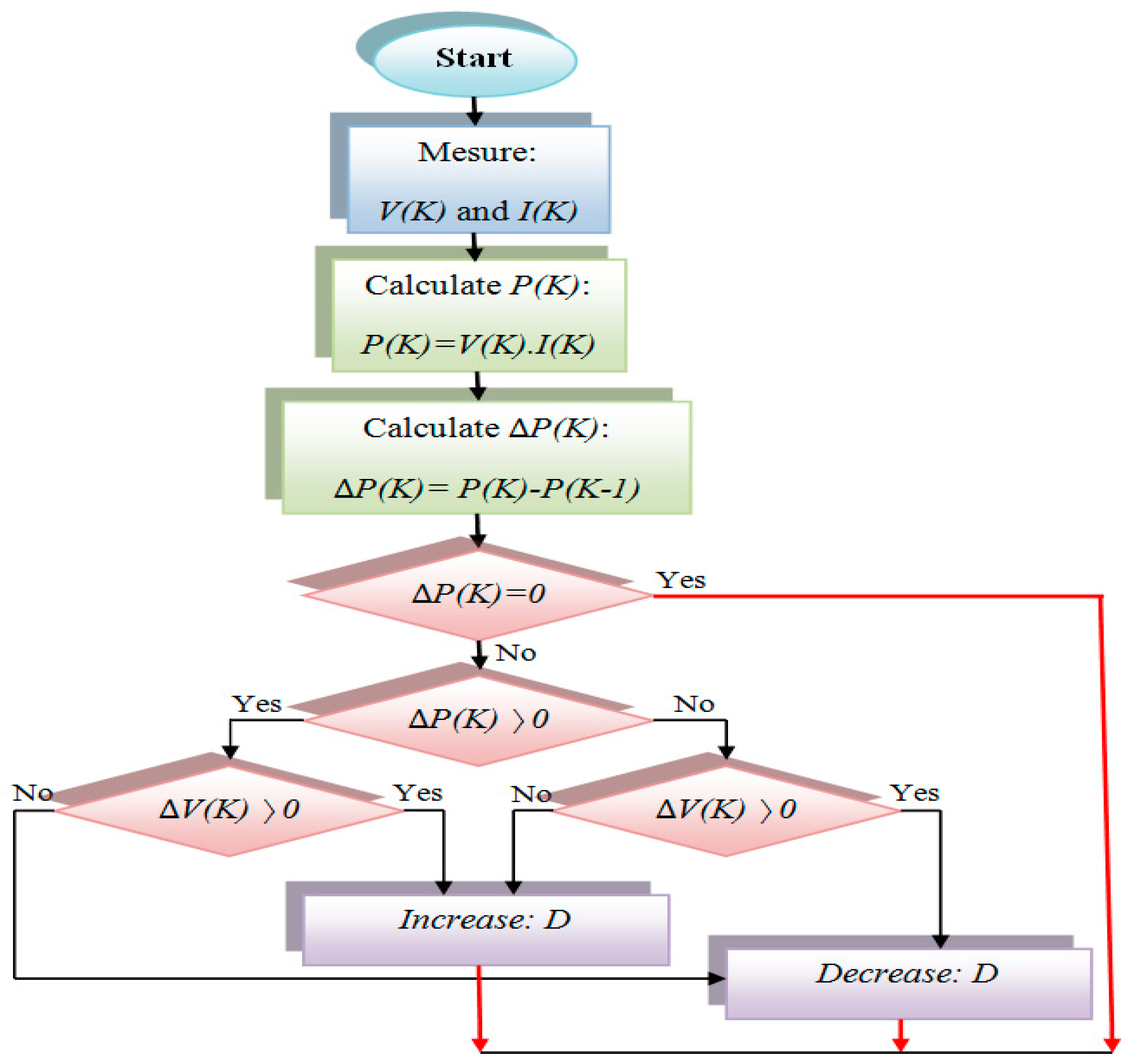
Since the 1970’s, the P&O (perturb and observe) method has been the most widely used approach in MPPT [5,12]. There are several variants of the P&O method, including the one described in Figure 12 below, whose results are compared with our fuzzy logic-based MPPT model.
The P&O method uses an algorithm that infers based on the duty ratio (increases or decreases) until the MPP is reached. As illustrated in Figure 12, V(K) and I(K) are continuously monitored, and the array output power P(K) is calculated. This instantaneous value P(K) is compared with the previously measured value of P(K − 1). If the two measured values are identical, this means that the maximum power point has been reached and no change is applied to the duty ratio. In the case where the output power and the voltage V(K) have changed between two successive measurements and in the same direction, the duty ratio is increased. If ΔP(K) increases while V(K) decreases and vice-versa, then the duty ratio is decreased [1,25].
In this paper, we compare the MPPT performance of the traditional P&O method with our fuzzy logic-based method. We illustrate in Figure 13 the fuzzy-based MPPT method and in Figure 14 the P&O MPPT method, as implemented on Simulink-Matlab®.

6. Simulations & Discussions

The fuzzy logic-based MPPT model has been built to increase efficiency for variable climatic conditions. Hence, the ambient temperature and incident irradiation on the PV panel is defined as an array of instantaneous input values. The mathematical representation of the PV system is defined in Equations (2)–(5), implemented together with the following parameters:
(1)
The number of PV modules connected in series is 14;
(2)
the number of photovoltaic cells in each PV module, connected in series z = 36;
(3)
Rp = 30 Ω, Rs = 15 × 10−3 Ω, Eg = 1.1 eV, n1 = 1, n2 = 2, k = 1.380 × 10⁻²³ J/K
(4)
q = 1.602 × 10⁻¹⁹ C;
(5)
I p h | ( T = 298 K ) = 3.25   A
(6)
the initial value of duty ratio was 0.1.
For the PV boost converter, Equations (6)–(9) were implemented together with the following numerical values [1,19]: C1 = 5.6 mF, C2 = C1, L = 3.5 mH. For the PV load block, Equation (10) has been implemented together with the parametric definitions from Equation (11):
Z ( s ) = a 2 s 2 + a 1 s + a 0 b 2 s 2 + b 1 s + b 0  
a 2 = R b s R b 1 R b p C b 1 C b p , a 1 = R b s R b 1 C b 1 + R b s R b p C b p + R b 1 R b p c b p + R b p R b 1 C b 1 , a 0 = R b s + R b 1 + R b p , b 2 = R b 1 R b p C b 1 C b p , b 1 = R b 1 C b 1 + R b p C b p , b 0 = 1.
Equation (10) and the parametric definitions (Equation (11)) were used in previous works [1,19,25]. To model lead-acid batteries, the following numerical values were used to complete the model: Rbs = 0.0013 Ω, Rb1 = 2.84 Ω, Rbp = 10 × 103 Ω, Cb1 = 2.5 mF, Cbp = 2 × 45 × 9 × 12 × 36,000/(1252 − 902) = 4.650 F.

6.1. Simulation Results for Fixed Climatic Conditions

To evaluate the fuzzy logic-based MPPT system, we analyzed its power extraction capabilities and stability versus the traditional P&O controller. In this particular simulation, the PV model described previously has been simulated with fuzzy logic and P&O controllers for fixed climatic conditions, i.e., an irradiance of 1000 W/m2 and temperature of 25 °C. The results are illustrated in Figure 15. For PV power output, the fuzzy logic-based MPPT method achieves maximum power output faster than the P&O controller (2.4 s compared to 12.3 s). Moreover, the fuzzy logic-based MPPT controller shows better performance not only in set point achievement, but also in stability and robustness (mitigation of power fluctuation). The PV generator reaches its maximum stable power output just after a minor overshoot at t = 2.1 s, and the output remains stable within a 0.0001 W range. In the meantime, the P&O controller is slower to reach its set point and is subject to significant oscillations prior to stability achievement. Moreover, a steady regime is subject to a 0.0002 W continuous oscillation. Similar behavior is observed with the PV voltage output, while the P&O controller achieves its maximum set point after 15 s, compared to a rapid 2.4 s with a fuzzy logic controller. Furthermore, the P&O controller is subjected to an important overshoot prior to stabilization with a continuous 0.02 V oscillation, compared to virtually no oscillation in the case of our fuzzy controller. The same trend is noticed with the converter output voltage, PV module current, and converter current, while the fuzzy logic-based controller shows amazingly better performance than the P&O controller in speed for maximum power achievement, stability, and robustness.
Performance improvement is the result of a faster and more appropriate variation of the duty ratio in the case of the fuzzy logic controller.

6.2. Simulation Results for the Changing Climatic Conditions

6.2.1. Simulation Results for a Fixed Temperature at 25 °C and Fast Increase of Irradiance from 500 Wm−2 to 1100 Wm−2

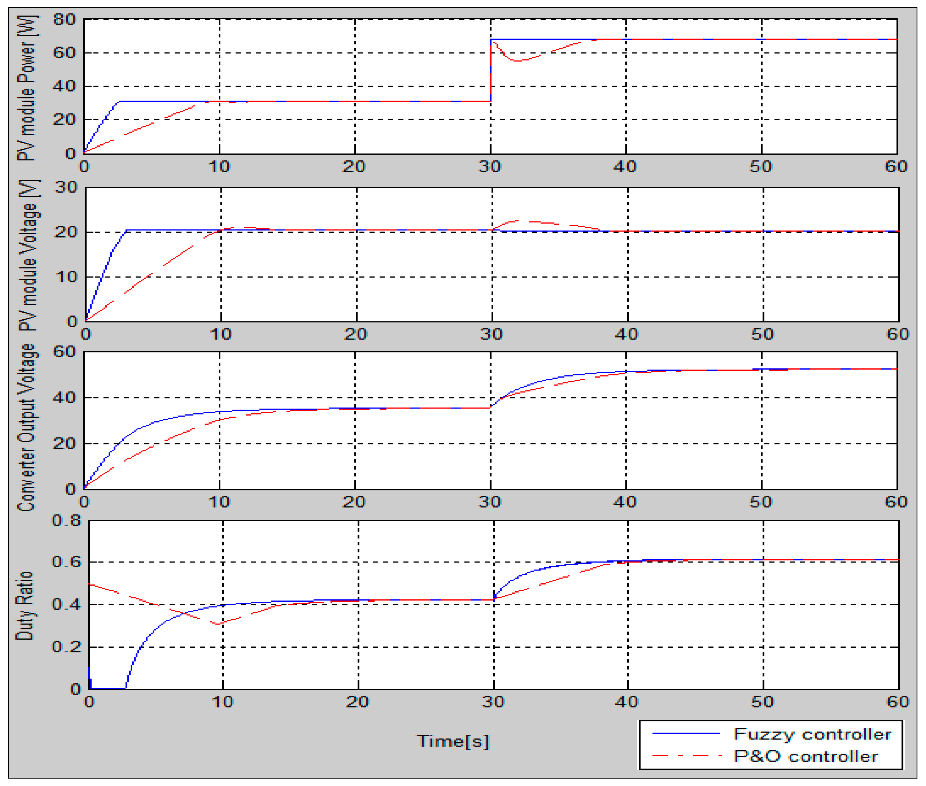
In this case, the irradiance was quickly increased from S = 500 Wm−2 to S = 1100 Wm−2 via a step function at t = 30 s. As illustrated in Figure 16, the fuzzy logic-based MPPT method shows much better performance than the P&O controller. The fuzzy controller responds to the irradiance change virtually instantaneously and regains stability with amazing robustness for PV module power and voltage output (reduced power oscillation). The P&O controller takes longer to achieve stability, which occurs after signal oscillations in the case of the PV power output and after overshoot in the case of the PV voltage output. We note that the duty ratio variation by the fuzzy logic controller is much more rapid than that of the P&O controller when they detect the irradiance change. The duty ratio gradient decreases in the case of the fuzzy controller as compared to a constant gradient in the case of the P&O controller. This probably helps with both the speed of maximum power achievement and oscillation and overshoot mitigation.

6.2.2. Simulation Results for a Fixed Temperature at 25 °C and Slow Increase of Irradiance from 500 Wm−2 to 650 Wm−2

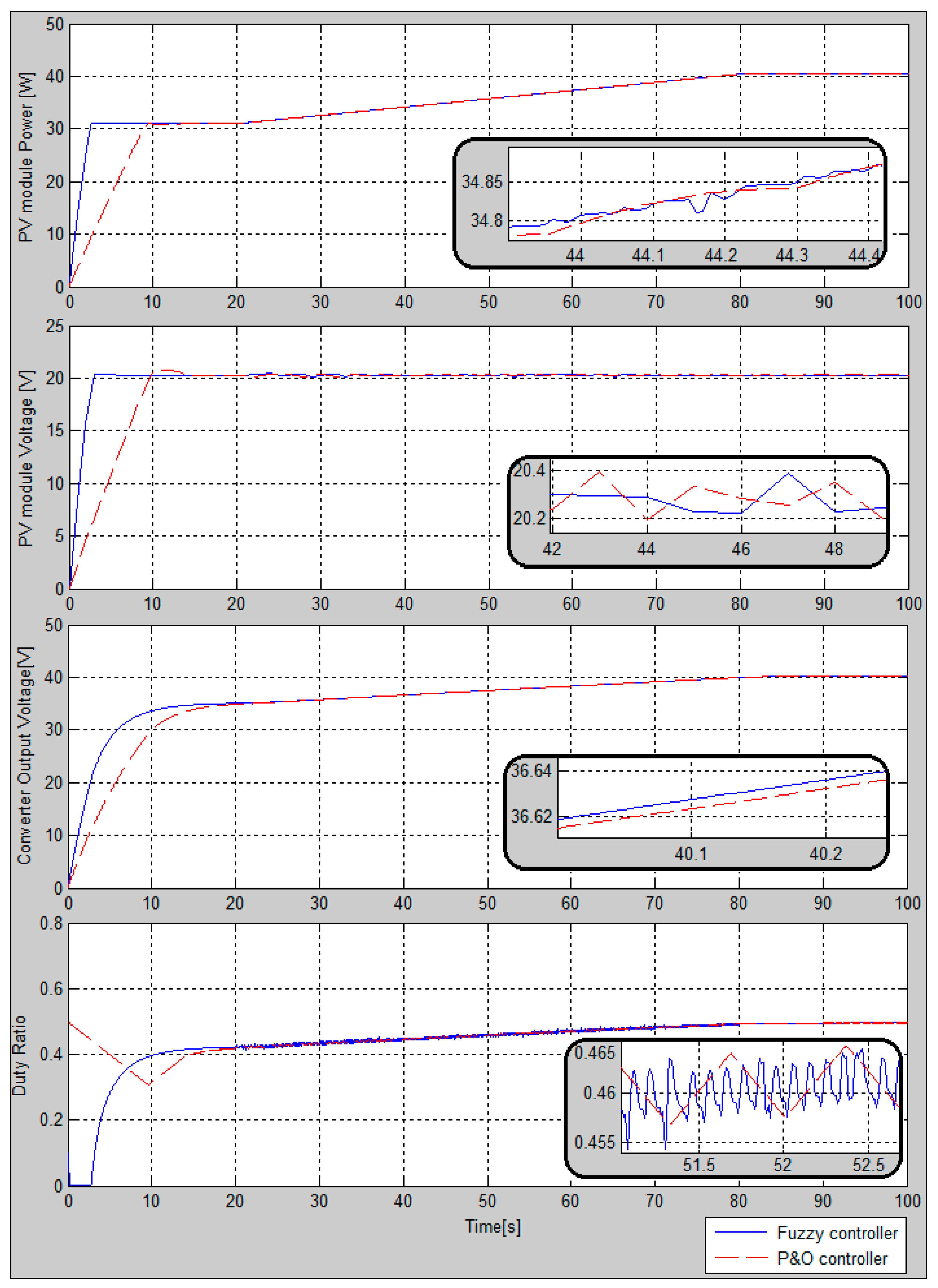
In this case, we evaluate the relative performance of the P&O and a fuzzy logic-based controller for fixed temperature and slow irradiance increase from 500 Wm−2 to 650 Wm−2. As illustrated in Figure 17, the irradiance is slowly and continuously increased from S = 500 Wm−2 at t = 20 s up to S = 650 Wm−2 at t = 80 s. In this case, we see that both controllers show almost similar performance.

6.2.3. Simulation Results for Fixed Irradiance at 1000 Wm−2 and Fast Temperature Decrease from 40 °C to 10 °C.

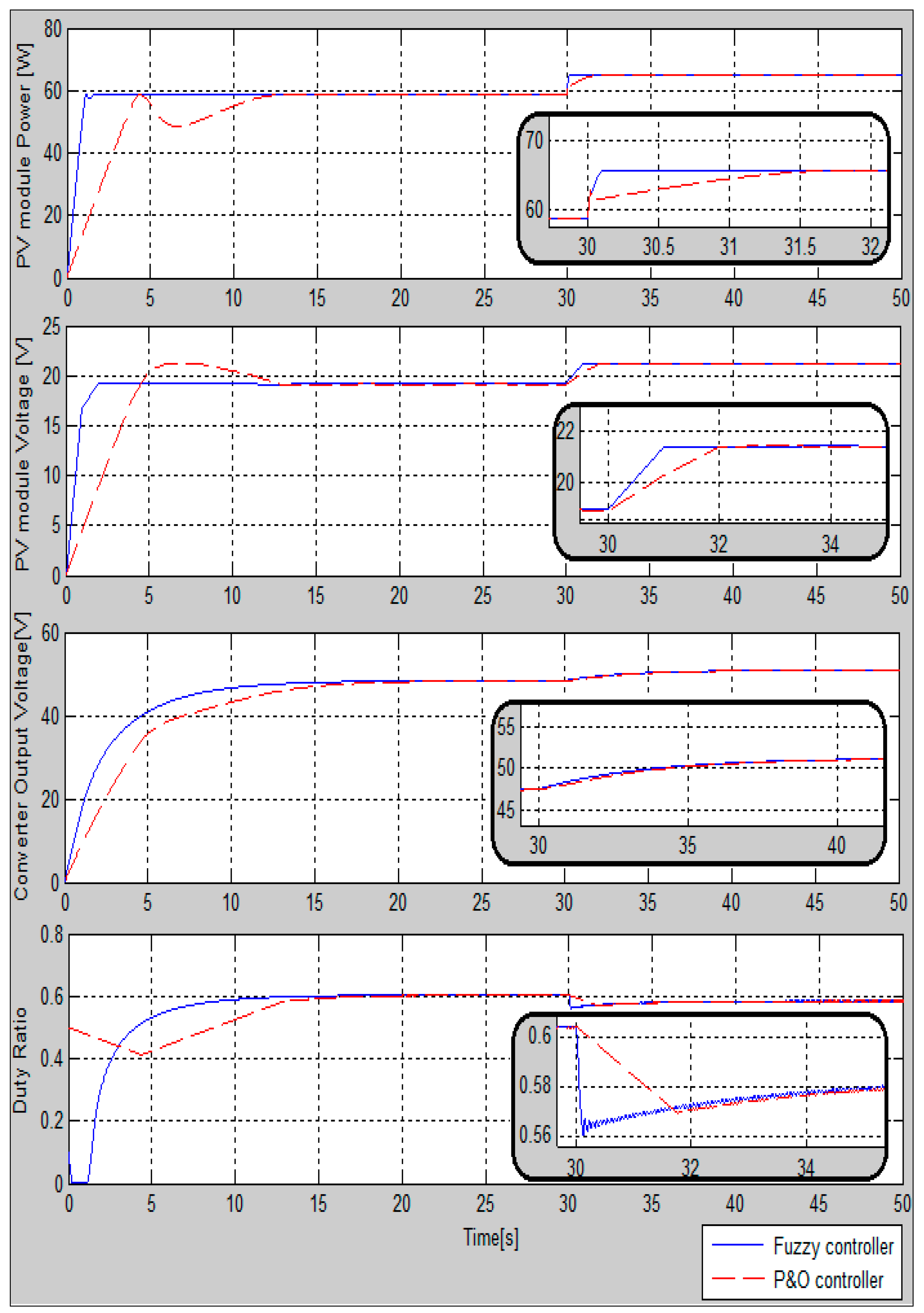
In this case, the temperature is decreased quickly via a step function at t = 30 s while keeping irradiance fixed at 1000 Wm−2. We note similar observations for the case with quick irradiance increase with fixed temperature. The fuzzy-based MPPT controller reacts quickly to the change via a much more aggressive duty ratio change Figure 18. This leads to a faster maximum power output achievement with comparable stability with the P&O controller.

6.2.4. Simulation Results for Fixed Irradiance at 1000 Wm−2 and Slow Temperature Increase from 25 °C to 30 °C

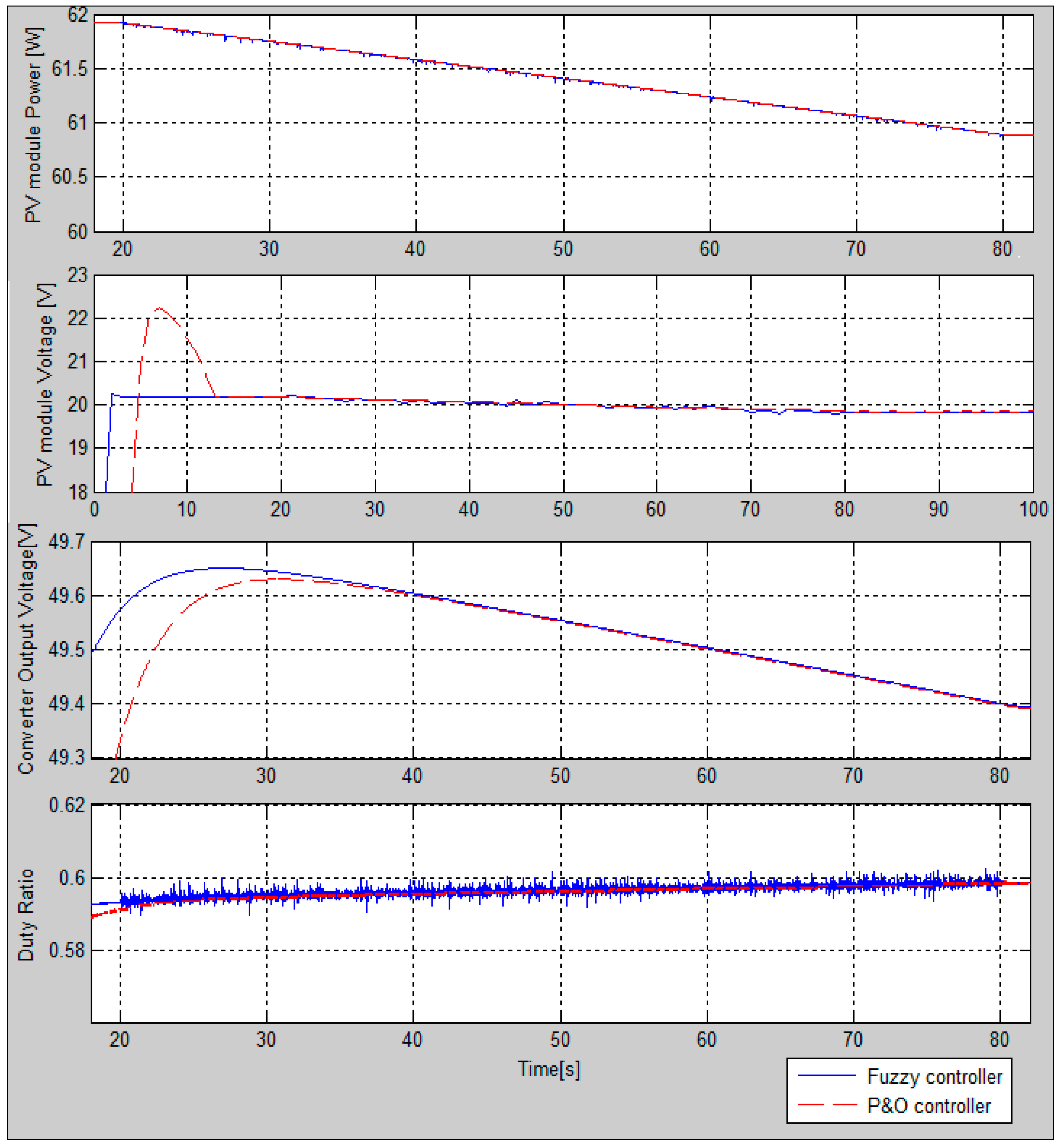
In this case, as seen in Figure 19, both P&O and fuzzy logic controllers show comparable performance in PV power output achievement and stabilization. However, a notable difference appears in the case of the PV voltage output. The fuzzy controller shows no significant overshoot compared to P&O controller. Moreover, better performance is shown by the fuzzy logic controller when it comes to voltage output in the converter.

7. Conclusions

The cost of solar energy is a major issue when it comes to its potential for greater development. Maximum power extraction is, therefore, an important parameter that influences the total production of PV systems and enables better payback of PV projects. In this paper, we have presented a fuzzy logic method which achieves faster and more stable power output at MPP from PV modules. In order to illustrate the performance of this controller, a Matlab-Simulink® model was built, and simulations were done for different operation scenarios. The results were compared with commonly used P&O controllers. Simulation results proved higher efficiency in maximum power tracking for the fuzzy logic controller. The simulations showed that most significant performance differences were achieved with rapidly varying parameters that influence power output (temperature, irradiance). Moreover, the fuzzy logic-based controller, as compared to the P&O controller, shows better performance in maximum power tracking time delay, stability, and robustness in all cases. Better stability and robustness performances from the fuzzy logic-based controller offer major advantages in mitigation of power fluctuation. The fuzzy logic algorithm is a robust and efficient algorithm. Indeed, this algorithm works at the optimal point without oscillations. In addition, it is characterized by good transient behavior. However, the implementation of this type algorithm is easier than conventional algorithms.
We can conclude that the use of fuzzy logic for the control MPPT presents a very interesting advantage, because there are always amazing results for the acceleration of the speed of MPP pursuit, the stability, achieved through the elimination of oscillations in steady state, and robustness. These amazing results are obtained after multiple tests by the engineer user’s experience, who decide the designs of the fuzzy regulator, but the disadvantage is that with each model of the photovoltaic system, we must study and specify the engineer’s own parameters and membership functions and the rules of his own fuzzy controller that help to achieve the MPP. For perspective, we propose a generalized study which can contain a global and generalized fuzzy model for any model of a photovoltaic system, if possible. The analysis in this paper should be useful for MPPT users, designers, and commercial PV manufacturers.

Author Contributions

Supervision, C.L. and A.I.; Visualization, T.O. and S.T.K.; Writing—original draft, G.F.T.K.

Funding

This research received no external funding.

Conflicts of Interest

The authors declare no conflict of interest.

Abbreviations

List of abreviation and symbols:
PVPhotovoltaic
MPPTMaximum power point tracking
MPPMaximum Power Point
P&OPerturb and observe
MOSFETMetal Oxide Semiconductor Field Effect Transistor frequency
DDuty cycle
ISCShort circuit current
VOCOpen circuit voltage
qElectron charge
kBoltzman’s constant
Egband-gap energy of the semiconductor
VInput voltage
IOutput current
IRSReverse saturation current
ISSaturation current
PWMPulse width modulation
SIrradiation
TTemperature
P-Vphotovoltaic characteristic P(V)
I-Vphotovoltaic characteristic I(V)
znumber of photovoltaic cells connected in series
Rsthe series resistance of photovoltaic cells
Rpparallel resistance of photovoltaic cells

References

  1. Cheikh, M.A.; Larbes, C.; Kebir, G.T.; Zerguerras, A. Maximum power point tracking using a fuzzy logic control scheme. Rev. Des Energ. Renouv. 2007, 10, 387–395. [Google Scholar]
  2. Khaligh, A.; Onar, O.C. Energy Harvesting: Solar, Wind, and Ocean Energy Conversion Systems; CRC Press: Boca Raton, FL, USA, 2017. [Google Scholar]
  3. Takun, P.; Kaitwanidvilai, S.; Jettanasen, C. Maximum Power Point Tracking Using Fuzzy Logic Control for Photovoltaic Systems. In Proceedings of the International Multiconference of Engineers and Computer Scientists, Hong Kong, China, 16–18 March 2011. [Google Scholar]
  4. Pandey, S.; Jena, P.K. A Review on Maximum Power Point Tracking Techniques for Photovoltaic Systems. Int. Res. J. Eng. Technol. 2017, 4, 1715–1720. [Google Scholar]
  5. Rai, A.; Awasthi, B.; Singh, S.; Dwivedi, C.K. A Review of Maximum Power Point Tracking Techniques for Photovoltaic System. Int. J. Eng. Res. 2016, 5, 539–545. [Google Scholar]
  6. Esram, T.; Chapman, P.L. Comparison of Photovoltaic Array Maximum Power Point Tracking Techniques. IEEE Trans. Energy Convers. 2007, 22, 439–449. [Google Scholar] [CrossRef] [Green Version]
  7. Hua, C.; Shen, C. Comparative study of peak power tracking techniques for solar storage system. In Proceedings of the APEC′98 Thirteenth Annual Applied Power Electronics Conference and Exposition, Anaheim, CA, USA, 15–19 February 1998. [Google Scholar]
  8. Subudhi, B.; Pradhan, R. A comparative study on maximum power point tracking techniques for photovoltaic power systems. IEEE Trans. Sustain. energy 2013, 4, 89–98. [Google Scholar] [CrossRef]
  9. Onat, N. Recent Developments in Maximum Power Point Tracking Technologies for Photovoltaic Systems. Int. J. Photoenergy 2010, 2010, 245316. [Google Scholar] [CrossRef]
  10. Oulcaid, M.; El Fadil, H.; Yahya, A.; Giri, F. Maximum Power Point Tracking Algorithm for Photovoltaic Systems under Partial Shaded Conditions. IFAC-PapersOnLine 2016, 49, 217–222. [Google Scholar] [CrossRef]
  11. Khalifa, M.A.; Saied, K.M.; Bitro, S.S.; Anwar, M.; Nizam, M. PV Power System Using Maximum Power Point Tracking (Increment Conductance Algorithm). Int. J. Innov. Res. Sci. Eng. Technol. 2014, 3, 12267–12275. [Google Scholar]
  12. Kamarzaman, N.A.; Tan, C.W. A comprehensive review of maximum power point tracking algorithms for photovoltaic systems. Renew. Sustain. Energy Rev. 2014, 37, 585–598. [Google Scholar] [CrossRef]
  13. Garg, V.K. A review paper on various types of MPPT techniques for PV system. Int. J. Innov. Eng. Res. Technol. 2014, 4, 320–330. [Google Scholar]
  14. Allataifeh, A.A.; Bataineh, K.; Al-Khedher, M. Maximum Power Point Tracking Using Fuzzy Logic Controller under Partial Conditions. Smart Grid Renew. Energy 2015, 6, 1–13. [Google Scholar] [CrossRef]
  15. Gheibi, A.; Mohammadi, S.M.A. Maximum Power Point Tracking of Photovoltaic Generation Based on the Type 2 Fuzzy Logic Control Method. Energy Procedia 2011, 12, 538–546. [Google Scholar] [CrossRef]
  16. El Khateb, A.H.; Rahim, N.A.; Selvaraj, J. Type-2 Fuzzy Logic Approach of a Maximum Power Point Tracking Employing SEPIC Converter for Photovoltaic System. J. Clean Energy Technol. 2013, 1. [Google Scholar] [CrossRef]
  17. Luo, F.L.; Hong, Y. Renewable energy systems: advanced conversion technologies and applications; CRC Press: Boca Raton, FL, USA, 2016. [Google Scholar]
  18. Cheng, P.C.; Peng, B.R.; Liu, Y.H.; Cheng, Y.S.; Huang, J.W. Optimization of a Fuzzy-Logic-Control-Based MPPT Algorithm Using the Particle Swarm Optimization Technique. Energies 2015, 8, 5338–5360. [Google Scholar] [CrossRef] [Green Version]
  19. Larbes, C.; Cheikh, S.M.A.; Obeidi, T.; Zerguerras, A. Genetic algorithms optimized fuzzy logic control for the maximum power point tracking in photovoltaic system. Renew. Energy 2009, 34, 2093–2100. [Google Scholar] [CrossRef]
  20. Mahdavi, M.; Li, L.; Zhu, J.; Mekhilef, S. An Adaptive Neuro-Fuzzy Controller for Maximum Power Point Tracking of Photovoltaic Systems. In Proceedings of the TENCON 2015—2015 IEEE Region 10 Conference, Macao, China, 1–4 November 2015. [Google Scholar]
  21. Reisia, A.R.; Moradi, M.H.; Jamasb, S. Classification and comparison of maximum power point tracking techniques for photovoltaic system: A review. Renew. Sustain. Energy Rev. 2013, 19, 433–443. [Google Scholar] [CrossRef]
  22. Kumar, J.; Bahrani, P. Comprehensive Review on maximum power point tracking methods for SPV system. Int. Res. J. Eng. Technol. 2017, 4, 1634–1639. [Google Scholar]
  23. Abbes, H.; Abid, H.; Loukil, K.; Toumi, A.; Abid, M. Etude comparative de cinq algorithmes de commande MPPT pour un système photovoltaïque. Revue des Energ. Renouv. 2014, 17, 435–445. [Google Scholar]
  24. Ezinwanne, O.; Fu, Z.; Li, Z. Energy performance and cost comparison of MPPT techniques for photovoltaics and other applications. Energy Procedia 2017, 107, 297–303. [Google Scholar] [CrossRef]
  25. Knopf, H. Analysis, Simulation, and Evaluation of Maximum Power Point Tracking (MPPT) Methods for a Solar Powered Vehicle. Computer-Produced Typeface. Master’s Thesis, Portland State University, Portland, OR, USA, 1999. [Google Scholar]
  26. Farahat, M.A.; Metwally, H.M.B.; Mohamed, A.A.E. Optimal choice and design of different topologies of DC-DC converter used in PV systems, at different climatic conditions in Egypt. Renew. Energy 2012, 43, 393–402. [Google Scholar] [CrossRef]
  27. Allouache, H.; Zegaoui, A.; Boutoubat, M.; Bokhtache, A.A.; Kessaissia, F.Z.; Charles, J.P.; Aillerie, M. Distributed photovoltaic architecture powering a DC bus: Impact of duty cycle and load variations on the efficiency of the generator. AIP Conf. Proc. 2018, 1968. [Google Scholar] [CrossRef]
  28. Jafari, R.; Yu, W. Fuzzy Modeling for Uncertainty Nonlinear Systems with Fuzzy Equations. Math. Probl. Eng. 2017, 2017, 8594738. [Google Scholar] [CrossRef]
  29. Jose, P.; Jose, P.R. Grid Connected Photovoltaic System with Fuzzy Logic Control Based MPPT. Int. J. Eng. Innov. Technol. 2014, 3, 142–148. [Google Scholar]
  30. Algazar, M.M.; El-Halim, H.A.; Salem, M.E.E.K. Maximum power point tracking using fuzzy logic control. Int. J. Electr. Power Energy Syst. 2012, 39, 21–28. [Google Scholar] [CrossRef]
  31. Bühler, H. Réglage par Logique Floue; Presses Polytechniques et Universitaires Romandes: Lausanne, Switzerland, 1994. [Google Scholar]
  32. Patcharaprakiti, N.; Premrudeepreechacharn, S.; Sriuthaisiriwong, Y. Maximum power point tracking using adaptive fuzzy logic control for grid-connected photovoltaic system. Renew. Energy 2005, 30, 1771–1788. [Google Scholar] [CrossRef]
  33. Won, C.Y.; Kim, D.H.; Kim, S.C.; Kim, W.S.; Kim, H.S. A new maximum power point tracker of photovoltaic arrays using fuzzy controller. In Proceedings of the 1994 Power Electronics Specialist Conference, Taipei, Taiwan, 20–25 June 1994. [Google Scholar] [Green Version]
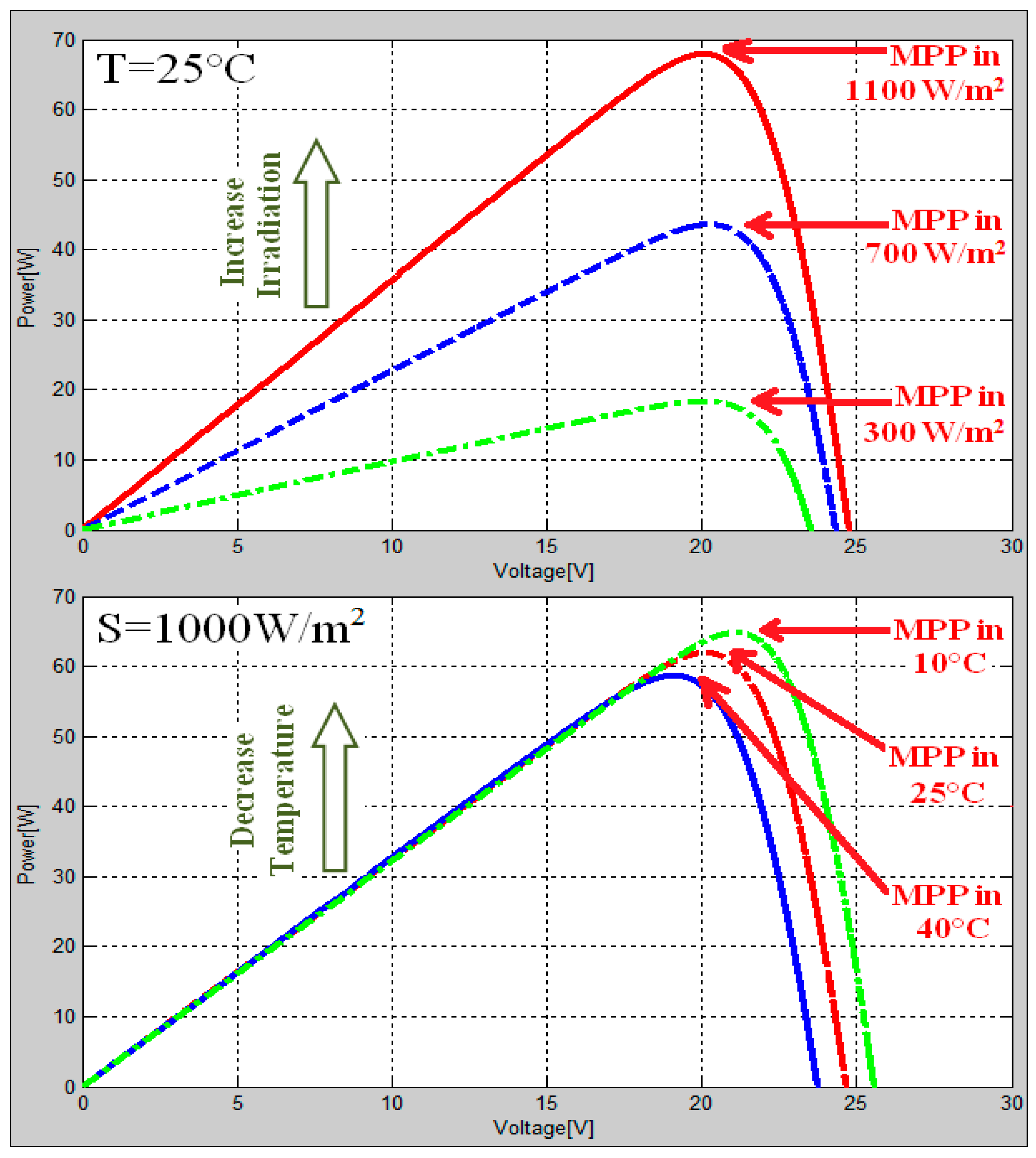
Figure 1. Variation of the maximum power point (MPP) with variations of irradiation and temperature.
Energies 11 03263 g001
Figure 2. Load effect on I-V photovoltaic characteristics.
Energies 11 03263 g002
Figure 3. The two-diode circuit model of a photovoltaic cell.
Energies 11 03263 g003
Figure 4. Photovoltaic maximum power point tracker (MPPT) architecture.
Energies 11 03263 g004
Figure 5. The direction change of the duty ratio D for tracking the MPP.
Energies 11 03263 g005
Figure 6. Output voltage vo(t) of the ideal DC-DC switching converter.
Energies 11 03263 g006
Figure 7. The ideal boost converter circuit.
Energies 11 03263 g007
Figure 8. Fuzzy Controller configuration.
Energies 11 03263 g008
Figure 9. Membership functions of the two entries: Input1, input2, and the output, with three sets of linguistic variables.
Energies 11 03263 g009
Figure 10. Proposed fuzzy rules decisions.
Energies 11 03263 g010
Figure 11. Max-min composition for the calculation of ∆D output.
Energies 11 03263 g011
Figure 12. Flowchart of the perturb and observe (P&O) MPPT algorithm used.
Energies 11 03263 g012
Figure 13. PV total system Simulink representation with a fuzzy logic controller.
Energies 11 03263 g013
Figure 14. Details of the MPPT subsystems of the P&O Controller.
Energies 11 03263 g014
Figure 15. Simulation results for fixed climatic conditions: Irradiance S = 1000 W/m2 and temperature T = 25 °C.
Energies 11 03263 g015
Figure 16. Simulation results with a fast increase in irradiance at t = 30 s from S = 500 W/m2 to S = 1100 W/m2 at constant temperature T = 25 °C.
Energies 11 03263 g016
Figure 17. Simulation results with slow increase from S = 500 W/m2 (t = 20 s) to S = 650 W/m2 (t = 80 s) at constant temperature T = 25 °C.
Energies 11 03263 g017
Figure 18. Simulation results with a fast decrease of temperature at t = 30 s from T = 40 °C to T = 10 °C, with a constant irradiance of S = 1000 W/m2.
Energies 11 03263 g018
Figure 19. Simulation results with a slow increase in temperature from T = 25 °C (t = 20 s) to T = 30 °C (t = 80 s), with fixed irradiance of S = 1000 W/m2.
Energies 11 03263 g019
Table 1. A comparative table of MPPT’s characteristics.
MPPT AlgorithmsPerturb & ObserveIncremental ConductanceFractional Open-Circuit Voltage Fractional Short-Circuit Current Fuzzy Logic ControlNeural NetworkParticle Swarm Optimization
Convergence speedVariesVariesMediumMediumFastFastFast
Implementation complexityLowMediumLowMediumHighHighMedium
True MPPTYesYesNoNoYesYesYes
Sensed parametersVoltage CurrentVoltage CurrentVoltage CurrentVariesVariesVaries
Efficiency (%)MediumMediumLowLowVery highVery highhigh
CostModerateModerateCheapCheapExpensiveExpensiveExpensive
StabilityNot stableStableNot stableNot stableVery stableVery stableVery stable