Article

Robust Tracking Control of a Three-Phase Charger under Unbalanced Grid Conditions

1
Faculty of Electrical Engineering, National Polytechnic Institute of Cambodia, Phnom Penh 12409, Cambodia
2
Electrical and Information Engineering, Seoul National University of Science and Technology, Seoul 01811, Korea
*
Author to whom correspondence should be addressed.
Energies 2018, 11(12), 3389; https://doi.org/10.3390/en11123389
Submission received: 6 November 2018 / Revised: 23 November 2018 / Accepted: 30 November 2018 / Published: 3 December 2018
(This article belongs to the Section F: Electrical Engineering)

Abstract

:
This paper presents a robust control technique for three-phase chargers under unbalanced grid conditions. The control method consists of inner-loop robust grid-current control and outer-loop proportional integral control for constant current (CC) and constant voltage (CV) control. A dual-current control for the inner-loop positive and negative sequence is employed to eliminate the unbalanced current caused by the grid so that a constant current and voltage can be provided to the batteries. The inner-loop robust controllers utilize state feedback with integral action in the dq-synchronous frame. A linear matrix inequality-based optimization scheme is used to determine stabilizing gains of the controllers to maximize the convergence rate to steady state in the presence of uncertainties. The uncertainties of the system are described as the potential variation range of the inductance and resistance in the L-filter.

1. Introduction

With the emergence of enormous amounts of plug-in hybrid electric vehicles (PHEVs) and electric vehicles (EVs) and the flourishing of renewable energy, the development of power storage has become an interesting topic. Therefore, the technology related to battery charging has drawn a lot of attention from governments, auto-makers, and researchers. In order to answer the demands for fast and efficient battery chargers, many control strategies have been proposed.
Classical Proportional Integral (PI) control has been proposed for single-phase chargers [1,2]. The charging scheme was designed based on constant-current (CC) and constant-voltage (CV) charging mode which provides shorter charging times compare to those of fixed voltage charging methods. However, the main drawback of PI controllers is gain tuning for both inner-loop and outer-loop controller. Furthermore, since the topology of these proposed methods is based on single-phase converters, the charging current limit is smaller compared to those of three-phase chargers.
Model predictive control (MPC) has been proposed in [3] for a bidirectional three-phase charger. This method could provide bidirectional power transfer with instantaneous mode charging capability and fast dynamic response. Even so, the charging method from power grid to vehicle is based on fixed voltage mode therefore the batteries need a longer time to be fully charged. In [4], another MPC-based control has also been proposed for a three-phase charger to charge Li-ion batteries. The controller outputs the optimum pulse width modulation (PWM) switching signal to provide the nearest output reference with fast convergence rate to the equilibrium point whose power factor is unity. However, this method requires a DC/DC converter to maintain the CC/CV charging stage. Furthermore, in unbalanced grid conditions these methods [3,4], fail to provide a constant voltage to the batteries due to the lack of negative sequence compensator. The MPC-based control method for a three-level single-phase charger described in [5] provides a smooth and low total harmonic distortion output to the battery. However, a single-phase based topology charger cannot supply as much output current as three-phase ones.
In [6], a PI control method was used in the AC/DC converter side to maintain dc-link voltage constant while deadbeat control is used in the DC/DC converter to regulate the charging current to battery. The deadbeat control provides really fast transient response which setting time reaches the steady state in just a few sampling instants. However, it is really sensitive to the parametric uncertainty of the system and measurement noise, particularly for high sampling rates.
Most of the abovementioned methods [1,2,4,6] are using bi-directional DC/DC converters for CC/CV operation along with DC/AC inverters for power factor control and DC-link voltage control. DC/DC converter topologies have been proposed for single-phase [7,8] and three-phase chargers [9,10] to improve the charging efficiency. In [7,10], three operational modes for bidirectional chargers i.e., grid-to-vehicle (G2V), vehicle-to-grid (V2G), and vehicle-to-home (V2H) were considered to provide a full bidirectional charger capability for electric vehicles. These methods adopt classical controllers such as PI which require multi-loop gain tunings. Moreover, they did not consider how to handle unbalanced grid conditions.
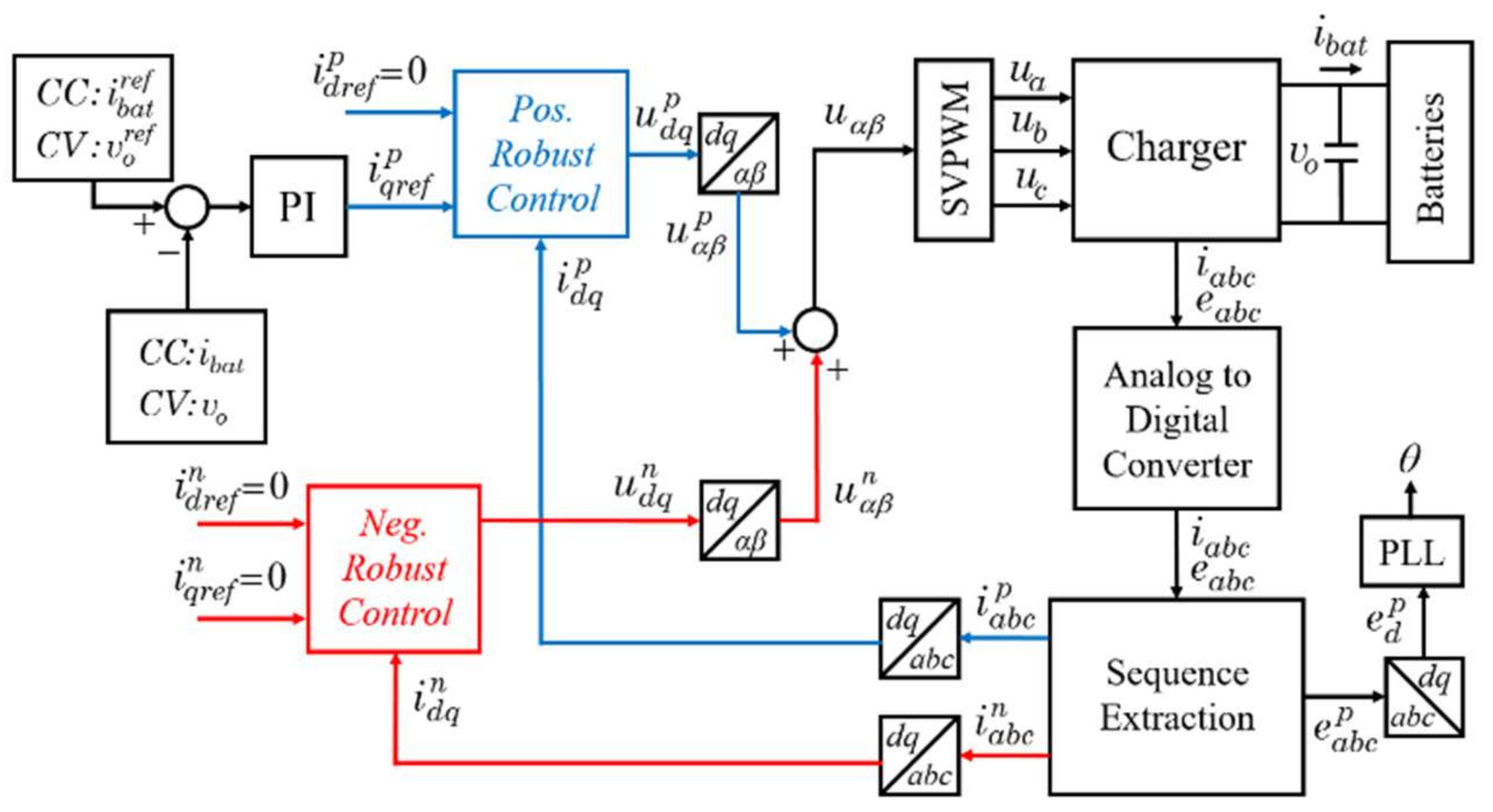
In this paper, a robust tracking control of a three-phase charger under unbalanced grid conditions is proposed without using DC/DC converter as an interface between the three-phase AC/DC converter and the batteries. Therefore, the charger is smaller in size and with less component expense. The battery is charged with a constant current until the voltage reaches the recommended maximum voltage, then the voltage is maintained constant until the current consumed by battery falls to a residual value. The control method consists of inner-loop robust grid-current control and outer-loop proportional integral control for constant current (CC) and constant voltage (CV) control. A dual-current control for the inner-loop positive and negative sequence is employed to eliminate the unbalanced current caused by the grid so that a constant current and voltage can be provided to the batteries. The inner-loop robust controllers utilize state feedback with integral action in the dq-synchronous frame. A linear matrix inequality-based optimization scheme is used to determine stabilizing gains of the controllers to maximize the convergence rate to steady state in the presence of uncertainties. The uncertainties of the system are described as the potential variation range of the inductance and resistance in the L-filter. The conventional phase-locked loop (PLL) method is considered in this paper to obtain the grid voltage phase angle.

2. Battery Chargers for EVs or PHEVs

Here, a detailed charger classification is presented. As discussed in the previous section, there are a few types of battery charger topologies such as a single-phase charger, three-phase charger with front end AC/DC converter and isolated DC/DC topologies, and only three-phase AC/DC topology. EVs or PHEVs can be recharged by connecting a plug to an external power source through an AC or DC charging system. The DC charging station is an off-board charger mounted at fixed place providing required DC power directly to the batteries inside the vehicle. The charging AC outlet can be single or three-phase and inevitably needs an on-board AC/DC charger with a power factor correction. The charger classification according to Society of Automotive Engineers (SAE) EV AC Charging Power Levels is summarized in Table 1, Table 2 and Table 3 for single-phase, three-phase and DC chargers, respectively [11,12].

3. System Description

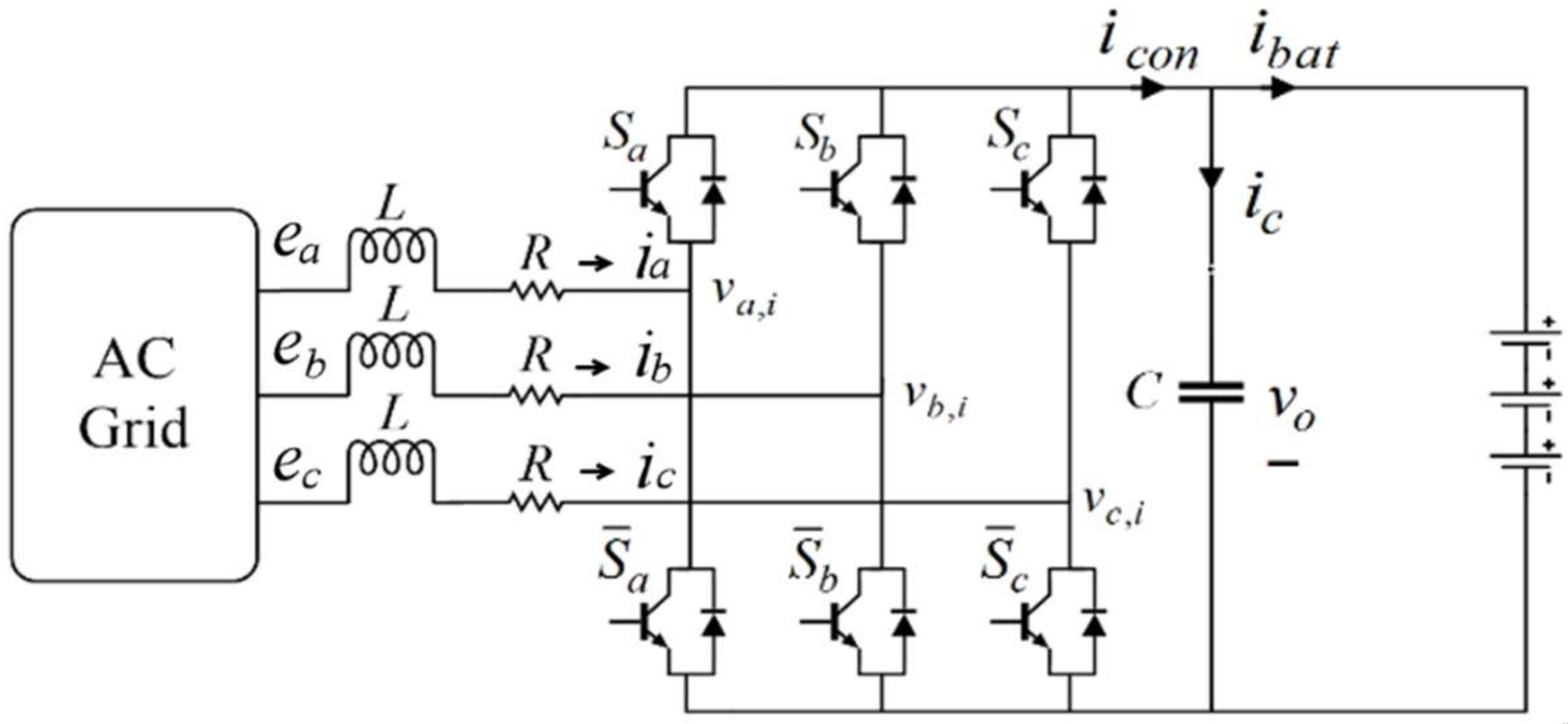
A three-phase charger is shown in Figure 1.
The dynamics of the line current is expressed in the abc-axis as follows:
{ L d i a ( t ) d t + R i a ( t ) = e a v a , i L d i b ( t ) d t + R i b ( t ) = e b v b , i L d i c ( t ) d t + R i c ( t ) = e c v c , i
where:
v a , i : = 2 u a u b u c 6 v o ( t ) v b , i : = u a + 2 u b u c 6 v o ( t ) v c , i : = u a u b + 2 u c 6 v o ( t )
The switches operate in continuous conduction mode, where two switches in each leg of the AC/DC charger should be operated in a complementary mode to avoid short circuits. The switching states of the charger is determined by ua, ub or uc as:
u a = { 1 ,   when   S a   is   on   and   S ¯ a   is   off   1 ,   when   S a   is   off   and   S ¯ a   is   on u b = { 1 ,   when   S b   is   on   and   S ¯ b   is   off   1 ,   when   S b   is   off   and   S ¯ b   is   on u c = { 1 ,   when   S c   is   on   and   S ¯ c   is   off   1 ,   when   S c   is   off   and   S ¯ c   is   on
It is quite challenging to control a three-phase converter in abc-frame due to its time-variant behavior, so the dq transformation is used to obtain DC like signal in dq-frame. Therefore, the dynamics (1) in abc-axis can be transformed to dq-axis as follows [13]:
d i d q ( t ) d t = A c i d q ( t ) + B c v o ( t ) u ( t ) + d c ( t )
where i d q ( t ) : = [ i d ( t ) i q ( t ) ] , u ( t ) = [ u d ( t ) u q ( t ) ] , d c ( t ) = [ 0 E m L ] , A c = [ R L ω ω R L ] , B c = [ 1 2 L 0 0 1 2 L ] , and ω is the angular frequency of the AC voltage source.
Any unbalanced three-phase voltage can be expressed by the sum of positive, negative and zero sequence [14]. However, the three-phase charger system has only three wires therefore the zero sequence is does not exist. Hence, the unbalanced current and voltage can be expressed as:
e a b c = e a b c p + e a b c n
i a b c = i a b c p + i a b c n
The positive and negative sequence of the grid voltage are assumed to be:
e a b c p = [ e a p e b p e c p ] = 1 3 [ 1 α α 2 α 2 1 α α α 2 1 ] [ e a e b e c ]
e a b c n = [ e a n e b n e c n ] = 1 3 [ 1 α 2 α α 1 α 2 α 2 α 1 ] [ e a e b e c ]
where α and α2 are phase-shifting operators and defined as:
α = 1 2 + j 3 2   and   α = 1 2 j 3 2
Substituting Equation (7) into Equation (6) yields:
e a b c p = 1 3 [ 1 1 2 1 2 1 2 1 1 2 1 2 1 2 1 ] [ e a e b e c ] + j 1 2 3 [ 0 1 1 1 0 1 1 1 0 ] [ e a e b e c ]
e a b c n = 1 3 [ 1 1 2 1 2 1 2 1 1 2 1 2 1 2 1 ] [ e a e b e c ] j 1 2 3 [ 0 1 1 1 0 1 1 1 0 ] [ e a e b e c ]
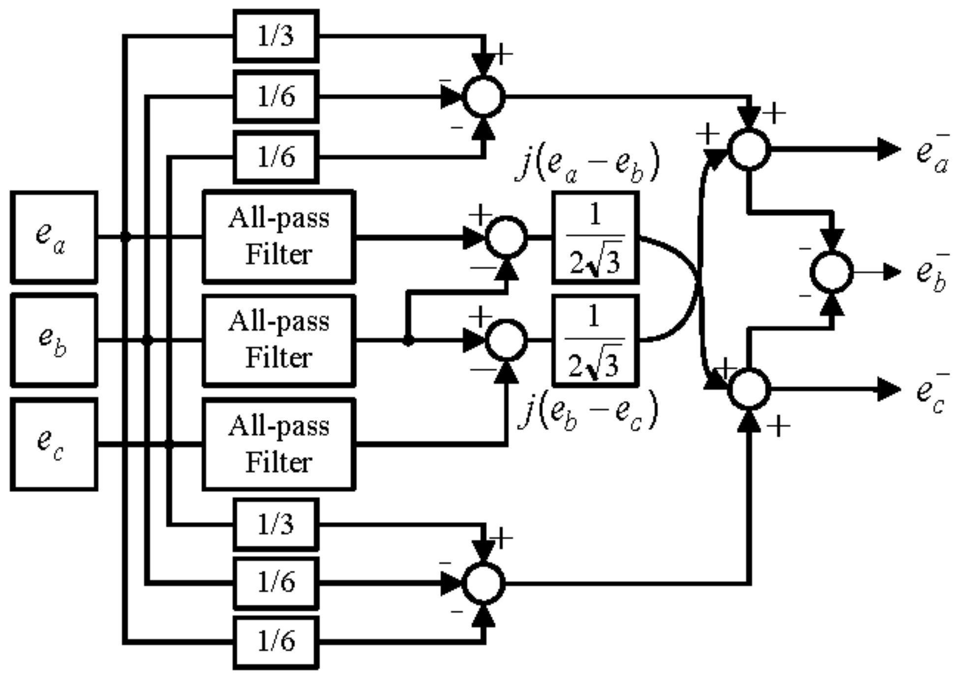
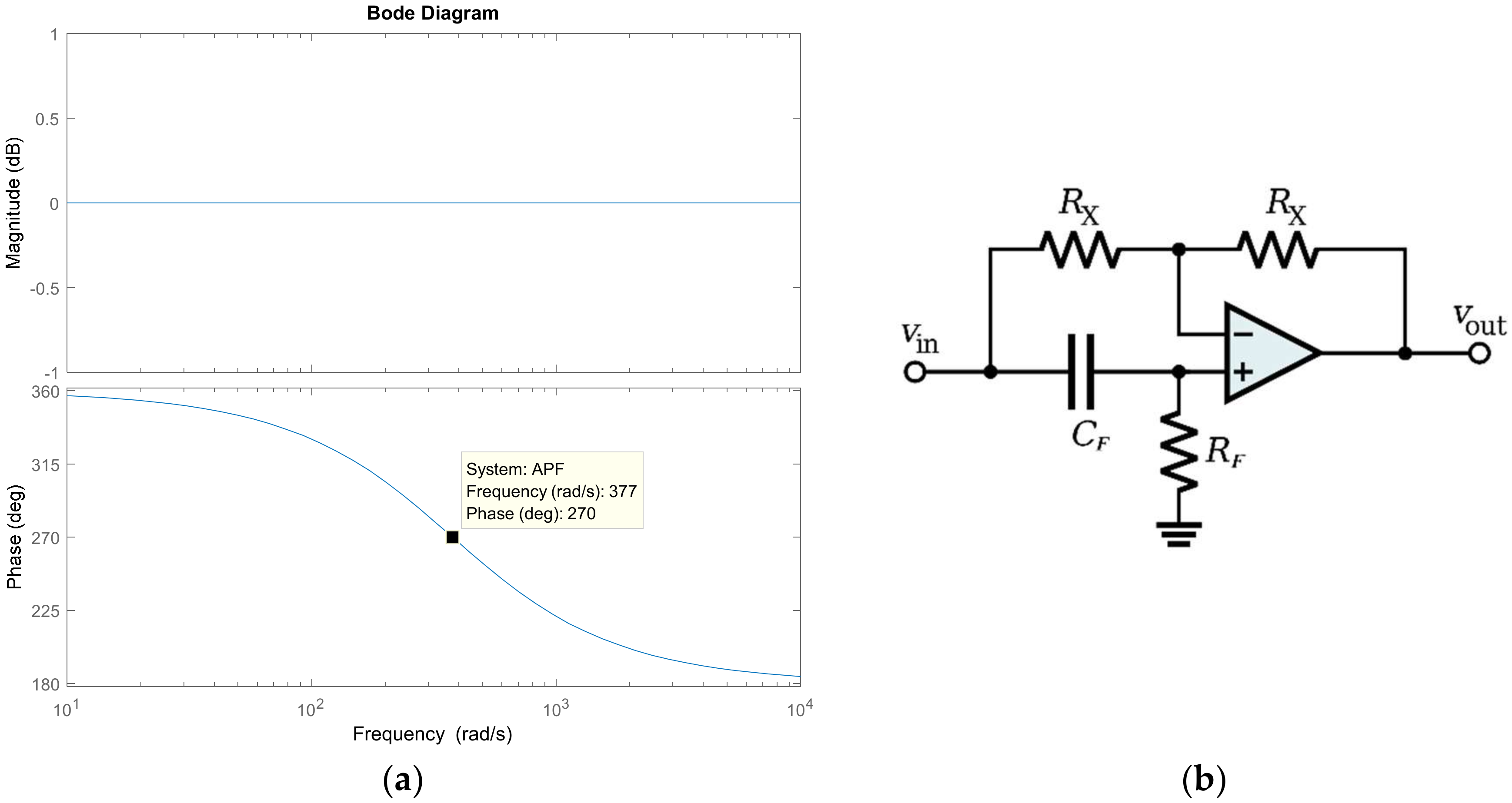
An all-pass filter allows all range of frequencies to pass, however it is used to obtain the imaginary part of Equation (8) by shifting 90° from the original phase. The characteristic of the all-pass filter is validated in Figure 2a using a Bode plot and the schematic of an all-pass filter is shown in Figure 2b.
The transfer function of the all-pass filter can be expressed as follows:
H ( s ) = 1 R F C F s 1 + R F C F s
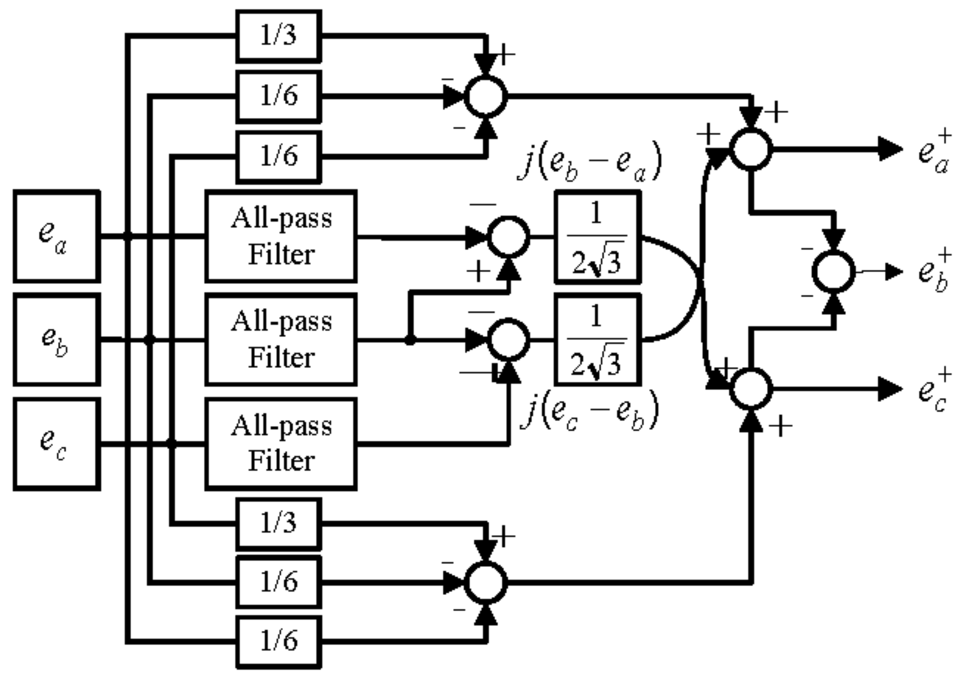
The same process is used to extract positive and negative sequence of grid current and voltage. The block diagrams of positive and negative sequence extraction are shown in Figure 3 and Figure 4, respectively.
From Equation (5), the current dynamics (4) can be rewritten as a combination of positive and negative sequence. The dynamic of both sequences is almost identical; however, the only difference is the sign of ω due to the inverse direction of the negative sequence vector rotation [15]. Then, we have:
d i d q p ( t ) d t = A c p i d q p ( t ) + B c v o ( t ) u d q p d c p ( t )
d i d q n ( t ) d t = A c n i d q n ( t ) + B c v o ( t ) u d q n d c n ( t )
where A c p : = [ R L ω ω R L ] , A c n : = [ R L ω ω R L ] , B c : = [ 1 2 L 0 0 1 2 L ] , d c p : = [ 0 e q p L ] , d c n : = [ 0 e q n L ] i d q and u d q are the grid current and control input in dq-frame, respectively. The output voltage v o ( t ) is governed by the following dynamic equation:
C d v o ( t ) d t = i c o n ( t ) i b a t ( t )
where:
i c o n ( t ) = 3 4 i d q T ( t ) u ( t )
and i c o n is the converter current and i b a t is an output current to the battery.
Model (10) can be transformed in the following discrete-time system with sampling time h:
x p ( k + 1 ) = A p x p ( k ) + B v o ( k ) u p ( k ) d p ( k )
x n ( k + 1 ) = A n x n ( k ) + B v o ( k ) u n ( k ) d n ( k )
where A p n = I 4 × 4 + A c p n , B = B c h , d p n = d c p n h , x p n = i d q p n .

4. Robust Controller Design

In this section, the uncertainties model of the system, offset-free control and robust optimal gain are discussed. Suppose that the value of L and R in each phase are equal but vary in certain ranges as indicated below:
L 1 L L 2
R 1 R R 2
Here, we denote the matrices (A, B) corresponding to the four possible combinations of the immoderate value of 1/L and 1/R as (Ai, Bi) (i = 1, 2, 3, 4) and suppose that the matrices (A, B) belongs to the polytopic uncertain set Ψ below:
Ψ = { n = 1 4 μ n ( A i , B i ) | n = 1 4 μ n = 1 , μ n 0 }
The uncertainties of the system can be any kind of variation, but should lies within the range (14). The system uncertain range can be determined as:
L n o m / μ L μ L n o m
R n o m / μ R μ R n o m
where Rnorm and Lnorm are nominal value of the filter resistance and inductance, respectively, and µ (>1) can be considered as a tuning parameter.
In consideration of compensating the offset error despite the system’s uncertainty model, the control law based on [16] is employed for Equation (13):
{ g p ( k ) = g p ( k + 1 ) + ( x r e f p x p ( k 1 ) ) u p ( k ) = K p x p ( k ) + L p g p ( k )
{ g n ( k ) = g n ( k + 1 ) + ( x r e f n x n ( k 1 ) ) u ( k ) = K n x n ( k ) + L n g n ( k )
where K p n and L p n are state feedback and integrator gains, respectively. Because of the integrator in Equation (17), the steady-state error between the reference state x r e f p n and the grid-current x p n will be compensated provided that the closed-loop system is stable.
In order to eliminate the unbalanced current caused by negative sequence and provide a constant charging current and voltage to the batteries, the reference state should be given as:
x r e f p n : = [ x d r e f p x q r e f p x d r e f n x q r e f n ] = [ 0 i q r e f p 0 0 ]
where x q r e f p = i q r e f p is generated by the outer-loop controller depending on its CC and CV control objectives.
The same process is used to find optimal gains for positive and negative sequence, so the procedure is unified. A systematic design method was proposed in [17] to obtain stabilizing state feedback gain K and integral gain L of Relation (17) using LMI. From relation (13) and (17), we get:
z ( k + 1 ) = A a z ( k ) + B a u ( k ) + D ( k )
where z ( k ) : = [ x ( k ) g ( k ) ] , A a : = [ A 0 2 × 2 C I 2 × 2 ] , B a : = [ B 0 2 × 2 ] , C = [ 1 0 0 1 ] , D ( k ) : = [ d ( k ) x r e f ] .
The control input u(k) can be rewritten as:
u ( k ) = F z ( k ) F : = [ K L ]
Assume that D(k) = 0 to determine stabilizing gain F, then the closed-loop system can be obtained as follows:
z ( k + 1 ) = ( A a + B a F ) z ( k )
The closed-loop dynamic (21) stable if there exists a positive-definite matrix W such that:
W ( A a + B a F ) T W ( A a + B a F ) > 0
It is obvious that the condition (22) holds for some W 0 > 0 ( W 0 < W )
W 0 ( A a + B a F ) T W ( A a + B a F ) > 0
By applying Schur complement and uncertain set Equation (15) to Equation (22), we get [17]
[ S 0 S 0 T A a i T + H T B a i T A a i S 0 + B a i H S ] > 0 ,   ( i   =   1 , , 4 ) ,  
where H : = F S 0 , S = W 1 , S 0 : = S 0 1 , A a i : = [ A i 0 2 × 2 C I 2 × 2 ] , B a i : = [ B i 0 2 × 2 ] , (i = 1,2,3,4).
To summarize, closed-loop system Equation (22) is asymptotically stable if there exist symmetric positive definite matrices S and S 0 and a matrix H such that Equation (24) holds and the stabilizing gain is given as:
F = H S 0 1
Assume that W 0 < α W or equivalent to
S < α S 0 ( 0 < α < 1 )
It can be expected that a small α would give a fast convergence of z to the origin. Therefore, to obtain optimal gain F such that the convergence time is minimized, the following optimization problem should be solved:
M i n i m i z e   α S , S 0 > 0 , α > 0 , H   subject   to   ( 24 )   and   ( 26 )
This optimization scheme is a generalized eigenvalue problem [18] which can be solve efficiently by the MATLAB 2014a LMI Toolbox YALMIP solver (MathWorks, Natick, MA, USA). The implementation of (27) can be done by following the YALMIP manual and it can be found on the YALMIP website (www.yalmip.github.io).

5. Dual-Loop Charging Control

In order to perform the battery charging process, most of the battery manufacturers recommend two charging stage i.e., constant current (CC) mode followed by constant voltage (CV) mode. The battery is charged with constant current until the voltage reaches the recommended maximum voltage, then the voltage is maintained constant until the current consumed by the battery falls to a residual value. The dual-loop control strategy will be adopted for these two charging states i.e., an outer-loop controller generates proper x q r e f p = i q r e f p depending on its CV or CC control objectives and the inner-loop controller (17) drives the state of x p n in (13) to follow x r e f p n .

5.1. Constant Voltage (CV) Charging Mode

Here, the outer-loop PI control for constant voltage charging is discussed. Let I r be the output of the outer-loop control, i.e.:
I r ( t ) = K p ( v o r e f v o ( t ) ) + K i ( v o r e f v o ( t ) ) d t
where v o r e f is the constant voltage reference for battery charge and v o ( t ) is the output voltage. Suppose that the dynamics of the inner-loop control in previous section is considerably fast so that we can assume:
i c o n ( t ) I r ( t )
for some current reference I r ( t ) . From Equations (11) and (29), we get:
C d v o ( t ) d t = K p ( v o r e f v o ( t ) ) + K i ( v o r e f v o ( t ) ) d t i b a t ( t )
or:
C d 2 v o ( t ) d t + K p d v o ( t ) d t + K i v o ( t ) = K i v o r e f .  
The K i and K p gain can be determined by considering the characteristic polynomial of Equation (31) and can be given as:
Δ ( s ) = s 2 + 2 ζ ω r s + ω r 2
or some appropriate value of ζ and ω r 2 ; we get:
K i = ω r 2
K p = 2 ζ ω r .
The control diagram of the constant voltage control of the three-phase charger is shown if Figure 5. The battery voltage is fed-back to the out-loop controller, which produces a reference current x q r e f p = i q r e f p .

5.2. Constant Current (CC) Charging Mode

In constant current charging stage, the battery pack is charged with a fixed current until the voltage reaches the recommended maximum voltage, then switches to a constant voltage charging stage. For the control of this constant current charging mode, an outer-loop PI is utilized to generate a reference signal x q r e f p = i q r e f p for inner-loop robust control with the same concept as CV charging discussed in previous section. The control structure of the proposed CC charging control is validated as shown in Figure 5.

6. Simulation Results

This section presents the results of the simulation to verify the proposed method. The simulation is implemented using MATLAB 2014a LMI toolbox (YALMIP solver) to obtain robust gain for the inner-loop controller. After receiving the optimal gains from MATLAB, the controllers were applied using PSIM simulation tool. The parameters of the system are shown in 
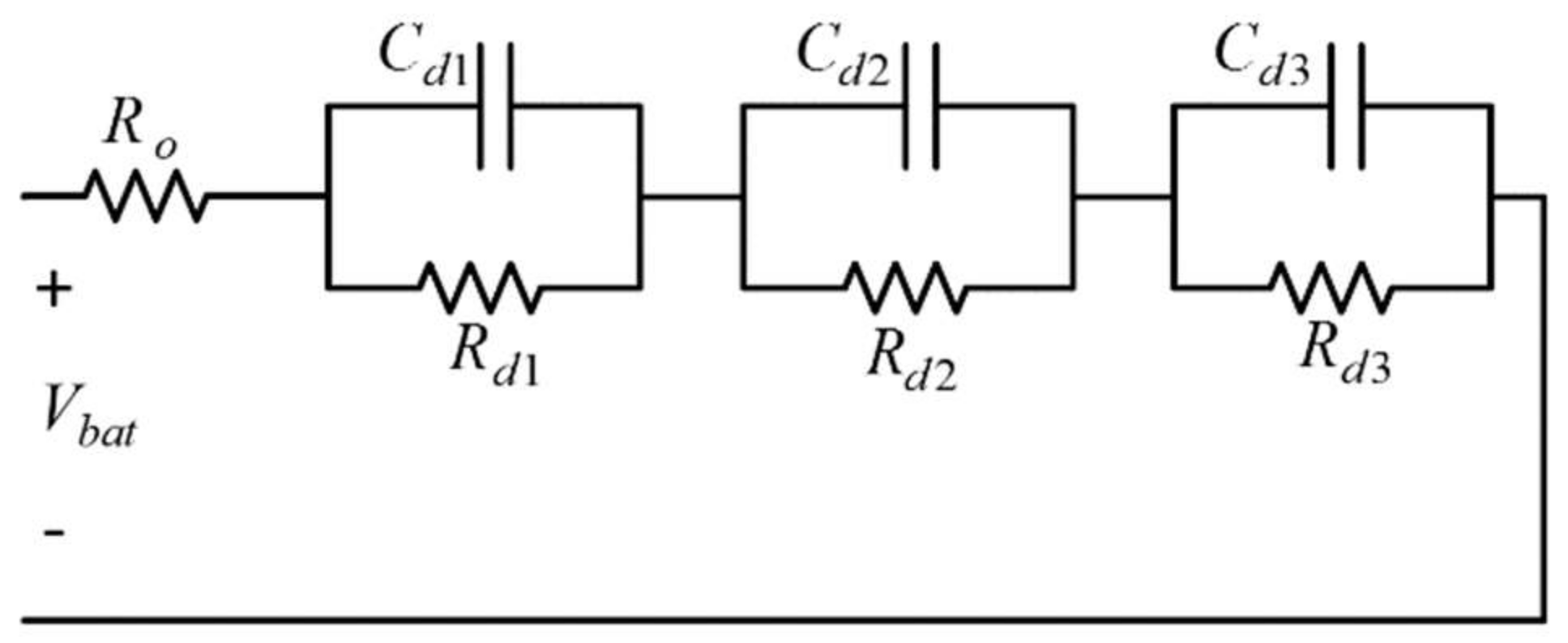
Table 4. The control algorithm is conducted using a DLL block from Microsoft Visual Studio and the sampling rate is set to 10 kHz. The 3-RC equivalent circuit of Figure 6 [18,19] is used for the simulation studies. The values of parameters are determined as R 0 = 0.01   Ω ,   R d 1 =   R d 2 =   R d 3 = 0.001   Ω ,     and   C d 1 = C d 2 = C d 3 = 1000   F with V b a t = 420   V .
The implementation of the proposed control strategy can be summarized as follows:
Step 1:
Derive the discrete-time model for based on Relation (13) using nominal value of inductance L and resistance R.
Step 2:
Choose an initial uncertainty range of the parameters Relation (14), e.g., µ = 1.1, and corresponding set Ψ.
Step 3:
Compute the state feedback gain Kpn and integrator gain Lpn for both positive and negative sequences by solving the optimization problem (26) using YALMIP LMI solver.
Step 4:
Implement the inner-loop current control Relation (17) to the charger.
Step 5:
If the closed-loop system shows serious overshoot or becomes unstable, then adjust the uncertainty range; i.e., raise the value of µ and repeat the procedure from Step 3.
Step 6:
After the closed-loop system becomes stable, then apply the outer-loop control for CC or CV.
Here, the simulation performances of the proposed charger are discussed. 
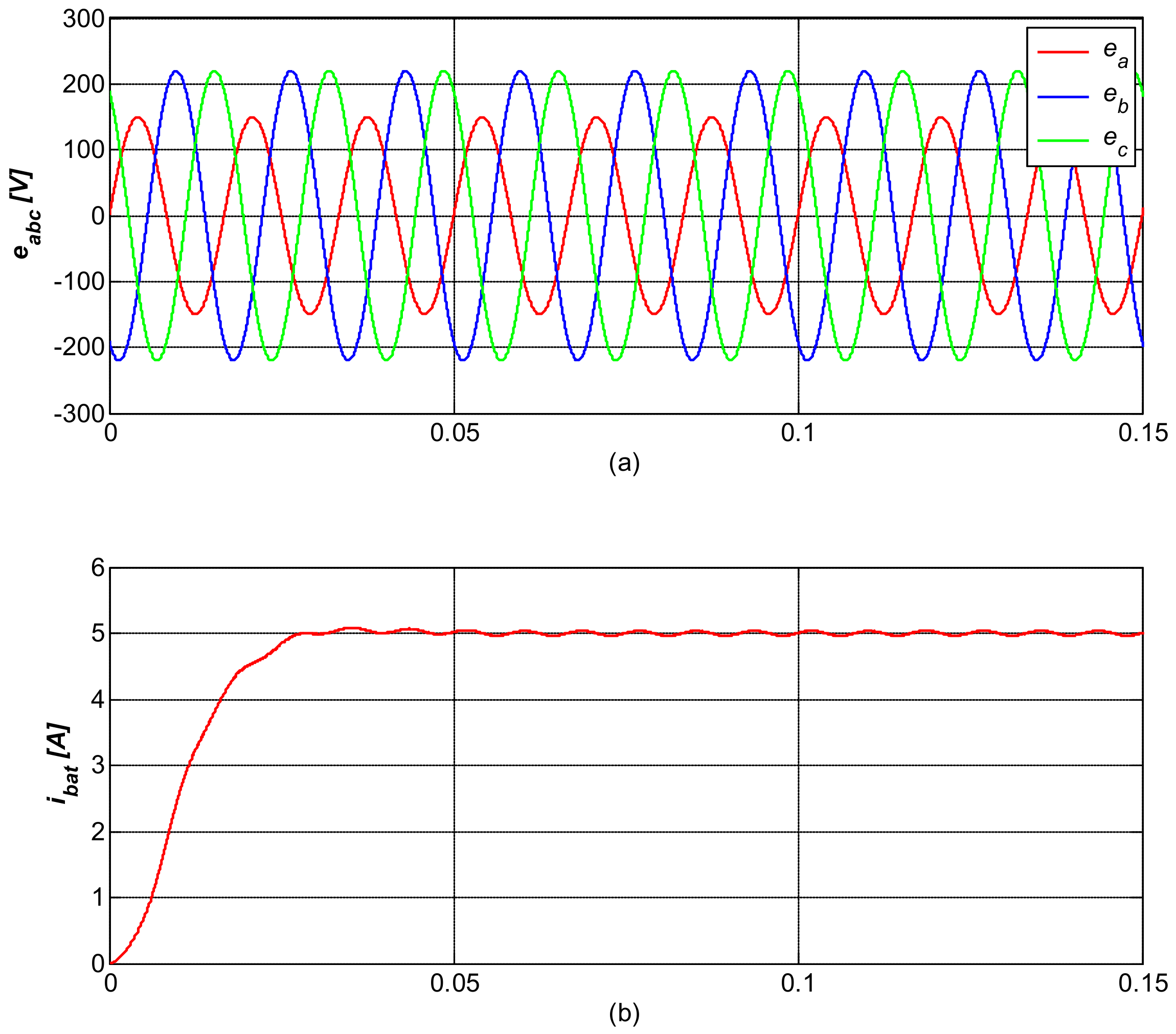
Figure 7a shows an unbalanced input three-phase grid-voltage supplied to charger in CC charging mode. In Figure 7b, the charger is still able to provide a considerable constant current even under unbalanced grid-voltage thanks to the its negative sequence compensator.
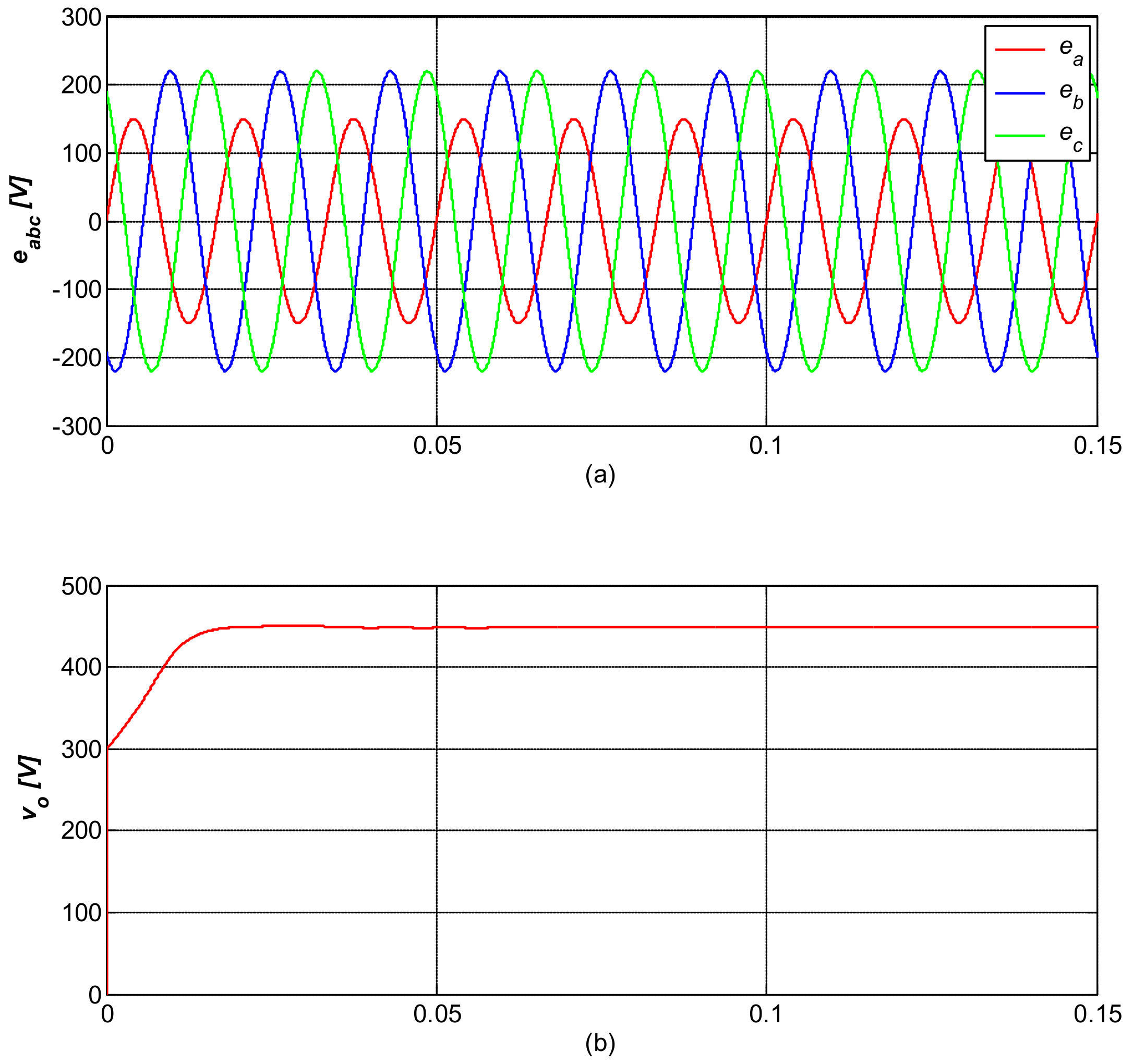
The CV charging mode is validated in Figure 8. We can see that the transient response of the battery voltage in CV mode is fast and constant even the three-phase input is unbalance as shown in Figure 8b.
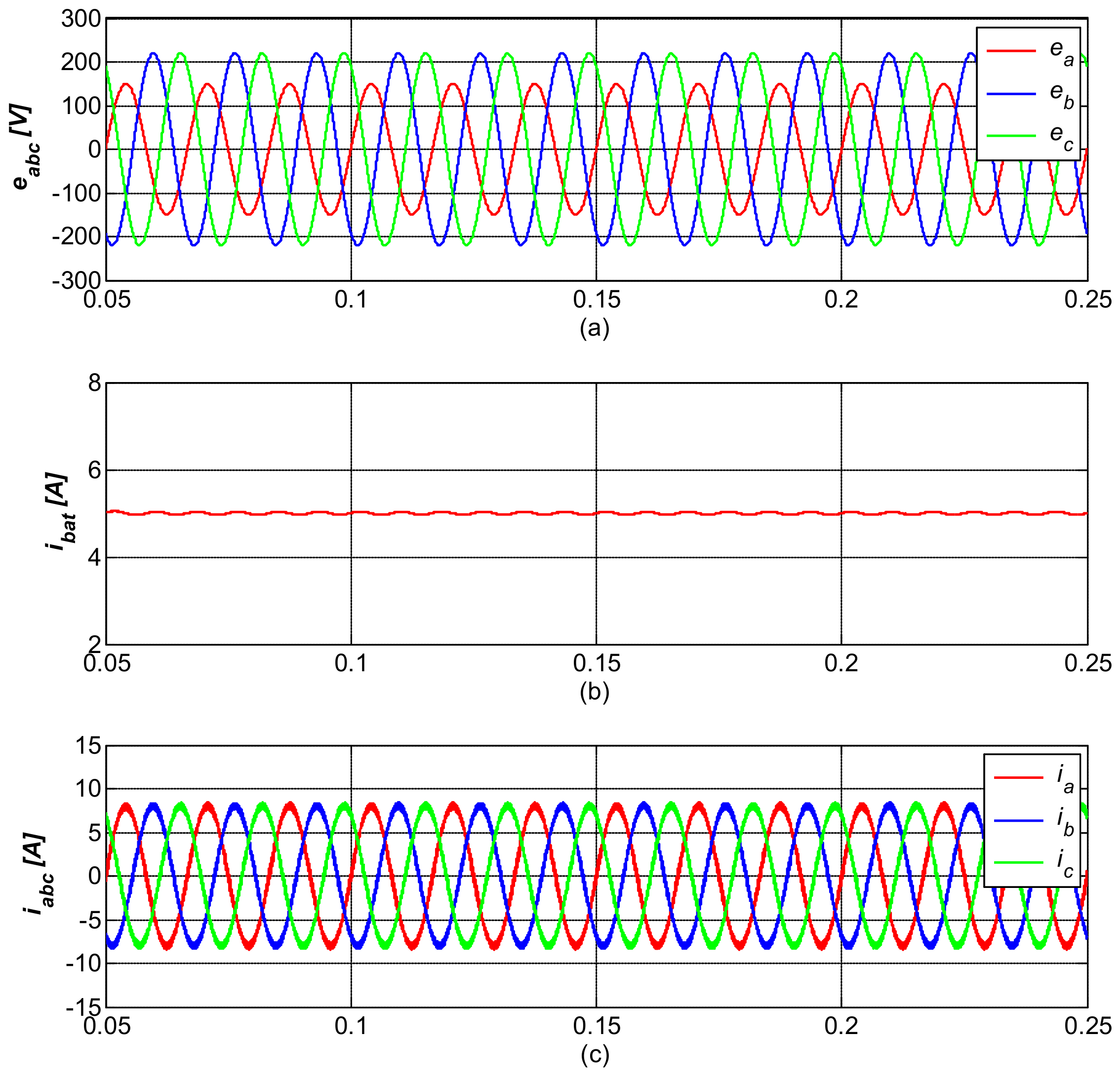
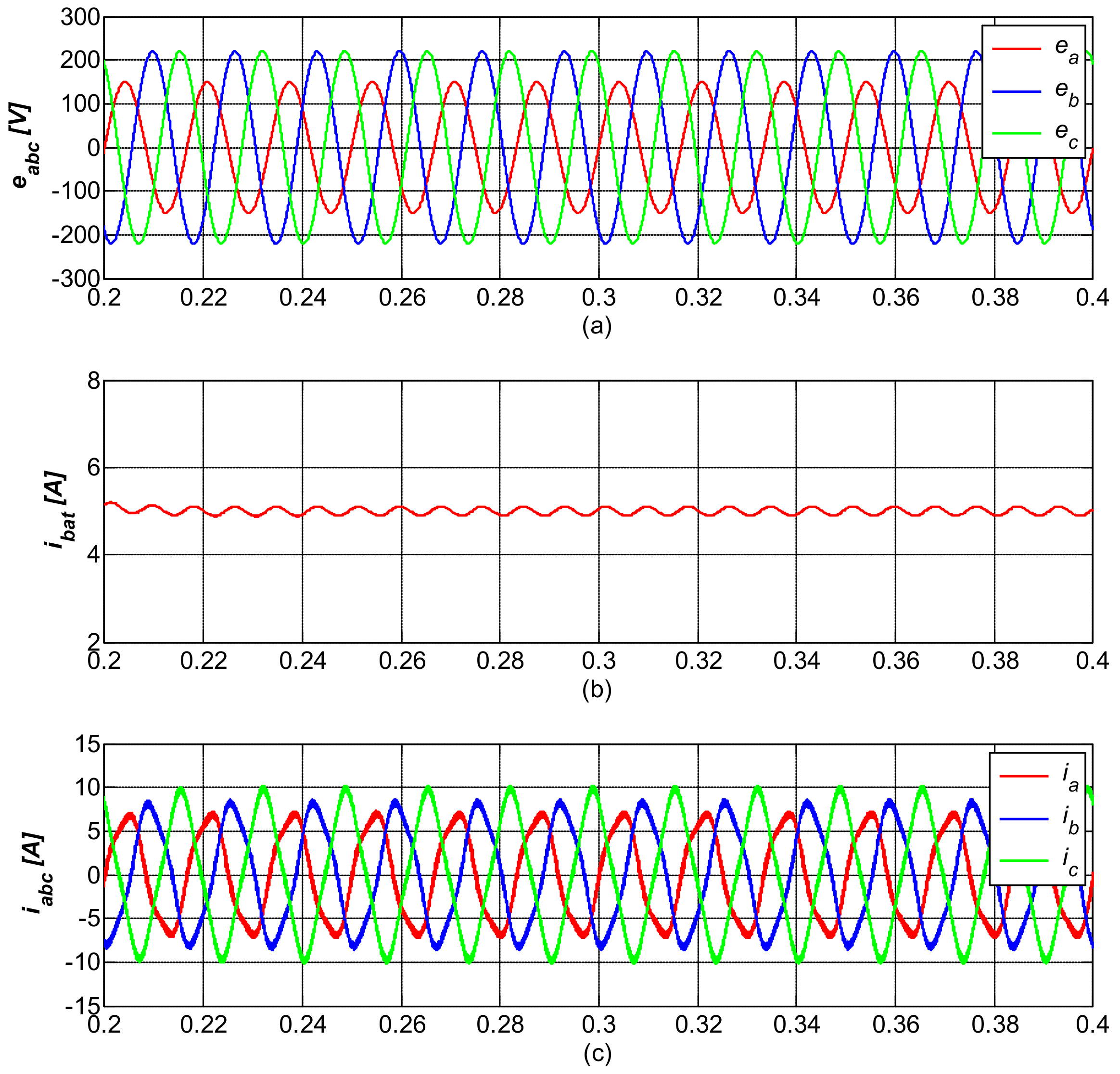
Let us discuss the comparison between the controller with and without negative sequence compensator in Figure 9 and Figure 10, respectively. It can be noted that the controller with negative sequence compensator performs well under unbalanced input grid-voltage conditions. Both the battery current and three-phase grid-current are remarkably acceptable, as shown in Figure 9b,c, respectively. In Figure 10, the simulation performance of the controller without negative sequence compensator is shown. Its performances, however, are not good compared to those of controller with sequence controller. It can be noted that the battery is has high oscillation and the grid-current does not show an appropriate waveform.
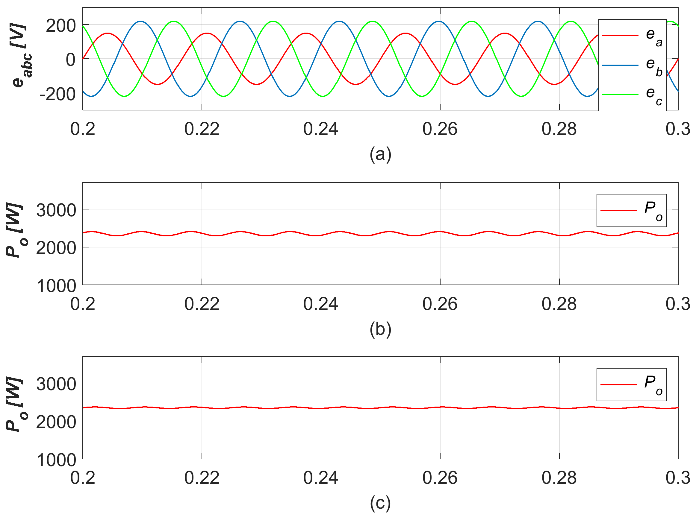
Figure 11 compares the output power of the proposed method with negative sequence compensator (Figure 11c), and without negative sequence compensator (Figure 11b). It is obvious to see that the proposed method provides a considerably constant output power to the batteries even under unbalanced grid conditions. On the other hand, it can be seen that without negative sequence compensator the charger fails to provide a constant power to the batteries. The output power is oscillating with double the system frequency which is not good considering the battery health conditions.
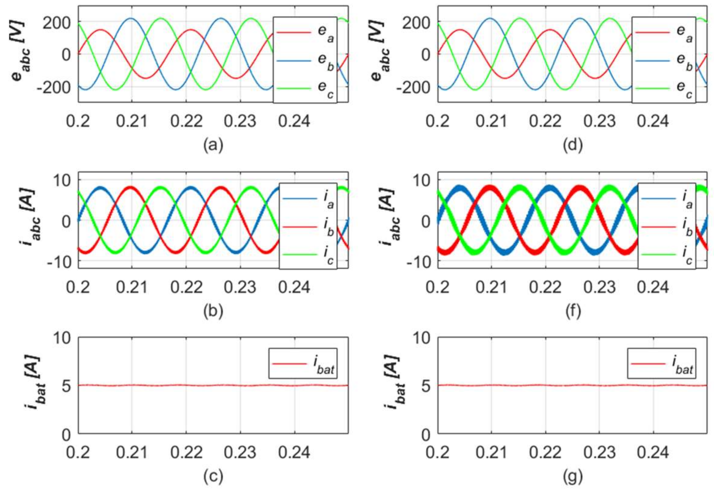
In Figure 12, the robustness of the proposed control method is validated. As it is shown in Figure 12a–c, the control method is implemented using a nominal value of the L-filter as shown in Table 4. The grid and charger output current perform really well, with real smoothness and symmetry although the phase-a grid-voltage drops to a certain level. To test the robustness of the proposed controller, the nominal value of L-filter is changed but works under the same robust stabilizing gains. The value of the inductance and resistance are reduced by half (× 0.5) which are 2.5 mH and 0.05 Ω, respectively. From Figure 12d–f, it can be seen that the charger provides almost identical constant output current as the one with nominal value. It can be assumed that the controller works pretty well under the uncertainty of the L-filter’s parameters.

7. Conclusions

This paper proposes a robust control strategy for a three-phase charger under unbalanced grid conditions. The control method consists of inner-loop robust grid-current control and outer-loop proportional integral control for constant current (CC) and constant voltage (CV) control. A paralleled current control for the inner-loop positive and negative sequence is employed to eliminate the unbalanced current caused by the grid so that a constant current and voltage can be provided to the batteries. The simulation results show that the proposed controller can provide a remarkable charging performance to the battery under unbalanced grid conditions. Moreover, the charger is able to supply a constant output power to the battery which results in better health conditions, even with an unsymmetrical voltage source. The robustness of the proposed method has been verified using parametric uncertainty of the L-filter. From an economic viewpoint, the proposed charger topology does not require an isolated DC/DC converter which leads to less component expense and a smaller installation size.

Author Contributions

Conceptualization, Y.I.L. and C.C.; Methodology, Y.I.L. and C.C..; Software, C.C.; Validation, C.C. and M.L.K.; Formal Analysis, C.C.; Investigation, C.C.; Resources, C.C. and M.L.K.; Data Curation, M.L.K.; Writing—Original Draft Preparation, C.C.; Writing—Review & Editing, C.C.; Visualization, M.L.K.; Supervision, Y.I.L.; Project Administration, Y.I.L.; Funding Acquisition, Y.I.L.

Funding

This research was funded by Seoul National University of Science and Technology grant number 2017-0793.

Conflicts of Interest

The authors declare no conflicts of interest.

Abbreviations

PLLphase locked loop
CCconstant current
CVconstant voltage
LMIlinear matrix inequality
EVelectric vehicle
PHEVplug-in hybrid electric vehicle
PWMpulse width modulation
PIproportional integral control
MPCmodel predictive control

Subscripts

abcsignal in abc-frame
dqsignal in dq-frame
ccontinuous time signal

Superscripts

psignal of positive sequence
nsignal of negative sequence
Ttranspose of matrix
refreference signal

Notations

Lfilter inductance
Rfilter resistance
vooutput voltage
iconconverter current
ibatoutput current
iccapacitor current
vabc,ipole-voltage in abc-frame
L1lower range of inductance
L2upper range of inductance
R1lower range of resistance
R2upper range of resistance
hsampling time
gintegrator state
zaugmented state of x and g
ucontrol input
Wweighting matrix
Kiintegrator gain
Kpproportional gain
CFall-pass filter capacitance
RFall-pass filter resistance
Rxall-pass filter feedback resistance
Lnomnominal value of L-filter inductance
Rnomnominal value of L-filter resistance
µuncertainty range
Ψuncertainty set
Kstate feedback gain
Lintegrator gain
Fstabilizing gain
xstate of the system

References

  1. Pinto, J.G.; Monteiro, V.; Goncalves, H.; Exposto, B.; Pedrosa, D.; Couto, C.; Afonso, J.L. Bidirectional battery charger with Grid-to-Vehicle, Vehicle-to-Grid and Vehicle-to-Home technologies. In Proceedings of the IECON 39th Annual Conference of the IEEE Industrial Electronics Society, Vienna, Austria, 10–13 November 2013. [Google Scholar]
  2. Zhou, X.; Wang, G.; Lukic, S.; Bhattacharaya, S.; Huang, A. Multi-function bi-directional battery charger for plug-in hybrid electric vehicle application. In Proceedings of the Energy Conversion Congress and Exposition, San Jose, CA, USA, 20–24 September 2009. [Google Scholar]
  3. Parvez, M.; Mekhilef, S.; Tan, N.M.L.; Akagi, H. Model predictive control of a bidirectional AC-DC converter for V2G and G2V applications in electric vehicle battery charger. In Proceedings of the Transportation Electrification Conference and Expo, Dearborn, MI, USA, 15–18 June 2014. [Google Scholar]
  4. Lim, J.S.; Lee, Y.L. Model Predictive Control of Current and Voltage for Li-Ion Battery Charger using 3-Phase AC/DC Converter. In Proceedings of the SICE Annual Conference, Taipei, Taiwan, 18–21 August 2010. [Google Scholar]
  5. Monteiro, V.; Meléndez, A.A.N.; Couto, C.; Afonso, J.L. Model Predictive Current Control of a Proposed Single-Switch Three-Level Active Rectifier Applied to EV Battery Chargers. In Proceedings of the IECON—42nd Annual Conference of the IEEE Industrial Electronics Society, Florence, Italy, 23–26 October 2016. [Google Scholar]
  6. Gallardo-Lozano, J.; Milanés-Montero, M.I.; Guerrero-Martínez, M.A.; Romero-Cadaval, E. Electric vehicle battery charger for smart grids. Electr. Power Syst. Res. 2012, 90, 18–29. [Google Scholar] [CrossRef]
  7. Kwon, M.; Choi, S. An Electrolytic Capacitorless Bidirectional EV Charger for V2G and V2H Applications. IEEE Trans. Power Electron. 2017, 32, 6792–6799. [Google Scholar] [CrossRef]
  8. Wajahat, U.K.T.; Saad, M.; Mutsuo, N. A Transformerless Reduced Switch Counts Three-Phase APF-assisted Smart EV Charger. In Proceedings of the IEEE APEC, Tampa, FL, USA, 26–30 March 2017. [Google Scholar]
  9. Wang, S.; Jiang, C.; Teng, H.; Bai, H.; Kirtley, J.L., Jr. Power-Loss Analysis and Efficiency Maximization of a Silicon-Carbide MOSFET-Based Three-Phase 10-kW Bidirectional EV Charger Using Variable-DC-Bus Control. IEEE J. Emerg. Sel. Top. Power Electron. 2016, 4, 880–892. [Google Scholar] [CrossRef]
  10. Hu, K.; Yi, P.; Liaw, C. An EV SRM Drive Powered by Battery/Supercapacitor with G2V and V2H/V2G Capabilities. IEEE Trans. Ind. Electron. 2015, 62, 4714–4727. [Google Scholar] [CrossRef]
  11. Surface Vehicle Recommended Practice J1772, SAE Electric Vehicle and Plug in Hybrid Electric Vehicle Conductive Charge Coupler; SAE International: Warrendale, PA, USA, 2010.
  12. Williamson, S.S.; Rathore, A.K.; Musavi, F. Industrial Electronics for Electric Transportation Current State-of-the-Art and Future Challenges. IEEE Trans. Ind. Electron. 2015, 62, 3021–3032. [Google Scholar] [CrossRef]
  13. Kim, S.K.; Choi, D.K.; Lee, K.B.; Lee, Y.I. Offset-Free Model Predictive Control for the Power Control of Three-Phase AC/DC Converters. IEEE Trans. Ind. Electron. 2015, 62, 7114–7126. [Google Scholar] [CrossRef]
  14. Ma, K.; Chen, W.; Liserre, M.; Blaabjerg, F. Power Controllability of a Three-Phase Converter with an Unbalanced AC Source. IEEE Trans. Ind. Electron. 2015, 30, 1591–1604. [Google Scholar] [CrossRef]
  15. Choeung, C.; Park, S.H.; Koh, B.K.; Lee, Y.I. Robust Tracking Control of a Three-Phase DC-AC Inverter for UPS Application under Unbalanced Load Conditions. In Proceedings of the IFAC Workshop on Control of Transmission and Distribution Smart Grids, Prague, Czech Republic, 11–13 October 2016. [Google Scholar]
  16. Lim, J.S.; Park, C.; Han, J.; Lee, Y.I. Robust Tracking Control of a Three-Phase DC-AC Inverter for UPS Applications. IEEE Trans. Ind. Electron. 2014, 61, 4142–4151. [Google Scholar] [CrossRef]
  17. Boyd, S.C.; Ghaoui, L.E.; Feron, E.; Balakrishnan, V. Linear Matrix Inequalities in System and Control Theory; SIAM: Philadelphia, PA, USA, 1994. [Google Scholar]
  18. He, H.; Xiong, R.; Fan, J. Evaluation of Lithium-Ion Battery Equivalent Circuit Models for State of Charge Estimation by an Experimental Approach. Energies 2011, 4, 582–598. [Google Scholar] [CrossRef] [Green Version]
  19. Nejad, S.; Gladwin, D.T.; Stone, D.A. A systematic review of lumped-parameter equivalent circuit models for real-time estimation of lithium-ion battery states. J. Power Sources 2016, 316, 183–196. [Google Scholar] [Green Version]
Figure 1. Three-phase bidirectional charger with L-filter.
Energies 11 03389 g001
Figure 2. (a) Bode plot of an all-pass filter (b) an all-pass filter schematic.
Energies 11 03389 g002
Figure 3. Positive sequence extraction block diagram.
Energies 11 03389 g003
Figure 4. Negative sequence extraction block diagram.
Energies 11 03389 g004
Figure 5. Control structure of the proposed method.
Energies 11 03389 g005
Figure 6. Battery equivalent circuit.
Energies 11 03389 g006
Figure 7. (a) Unbalanced input voltage (b) transient performance of battery current in constant current (CC) charging mode.
Energies 11 03389 g007
Figure 8. (a) Unbalanced input voltage (b) transient performance of battery voltage in constant voltage (CV) charging mode.
Energies 11 03389 g008
Figure 9. Steady-state performances of (a) input voltage, (b) battery current and (c) grid current; with negative sequence compensator in CC mode.
Energies 11 03389 g009
Figure 10. Steady-state performances of (a) input voltage, (b) battery current and (c) grid current; without negative sequence compensator in CC mode.
Energies 11 03389 g010
Figure 11. Steady-state performances of (a) input voltage, (b) output power without negative sequence compensator (c) output power with negative sequence compensator in CC mode.
Energies 11 03389 g011
Figure 12. Steady-state performances of (a) input voltage, (b) grid current and (c) battery current with nominal L-filter value; and (a) input voltage, (b) grid current and (c) battery current with 0.5× of nominal L-filter value.
Energies 11 03389 g012
Table 1. Single-phase Automotive Engineers (SAE) EV AC charging power level.
Nominal Supplied Voltage (V)Maximum Current (A)Output Power Level (kW)
120V AC, single-phase12 1.08
120V AC, single-phase16 1.44
208–240 V AC, single-phase16 3.3
208–240 V AC, single-phase32 6.6
208–240 V AC, single-phase≤80 ≤14.4
Table 2. Three-phase SAE EV AC charging power level.
Nominal Supplied Voltage (V)Maximum Current (A)Output Power Level (kW)
480 V AC, three-phase16 11
480 V AC, three-phase80 65
480 V AC, three-phase160 133
600 V AC, three-phase160 166
Table 3. SAE EV DC charging power level.
Nominal Supplied Voltage (V)Maximum Current (A)Output Power Level (kW)
200–450 V DC≤8036
200–450 V DC≤200 90
200–600 V DC≤400 240
Table 4. Simulation parameters.
ParameterValue
DC-Link capacitor4700 µF
Filter resistance0.1 Ω
Filter inductance5 mH
Sampling rate10 kHz
Constant current reference5 A
Constant voltage reference450 V

