Stability Analysis in Determining Safety Drilling Fluid Pressure Windows in Ice Drilling Boreholes


Abstract
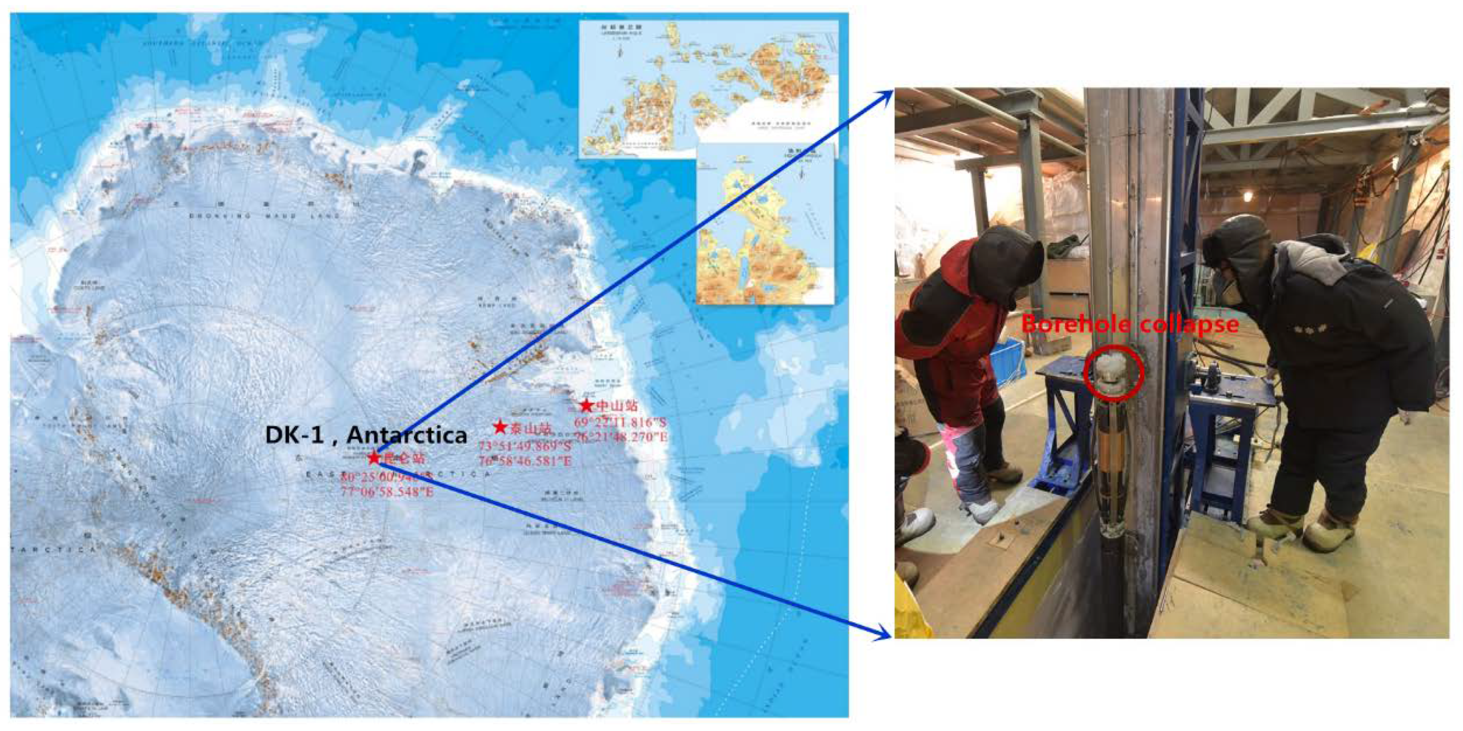
1. Introduction
2. Theory of Stability Analysis in Ice Drilling Boreholes
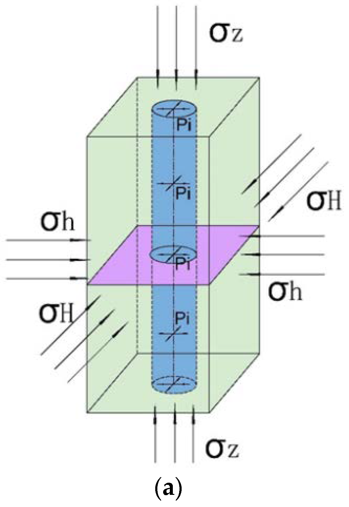
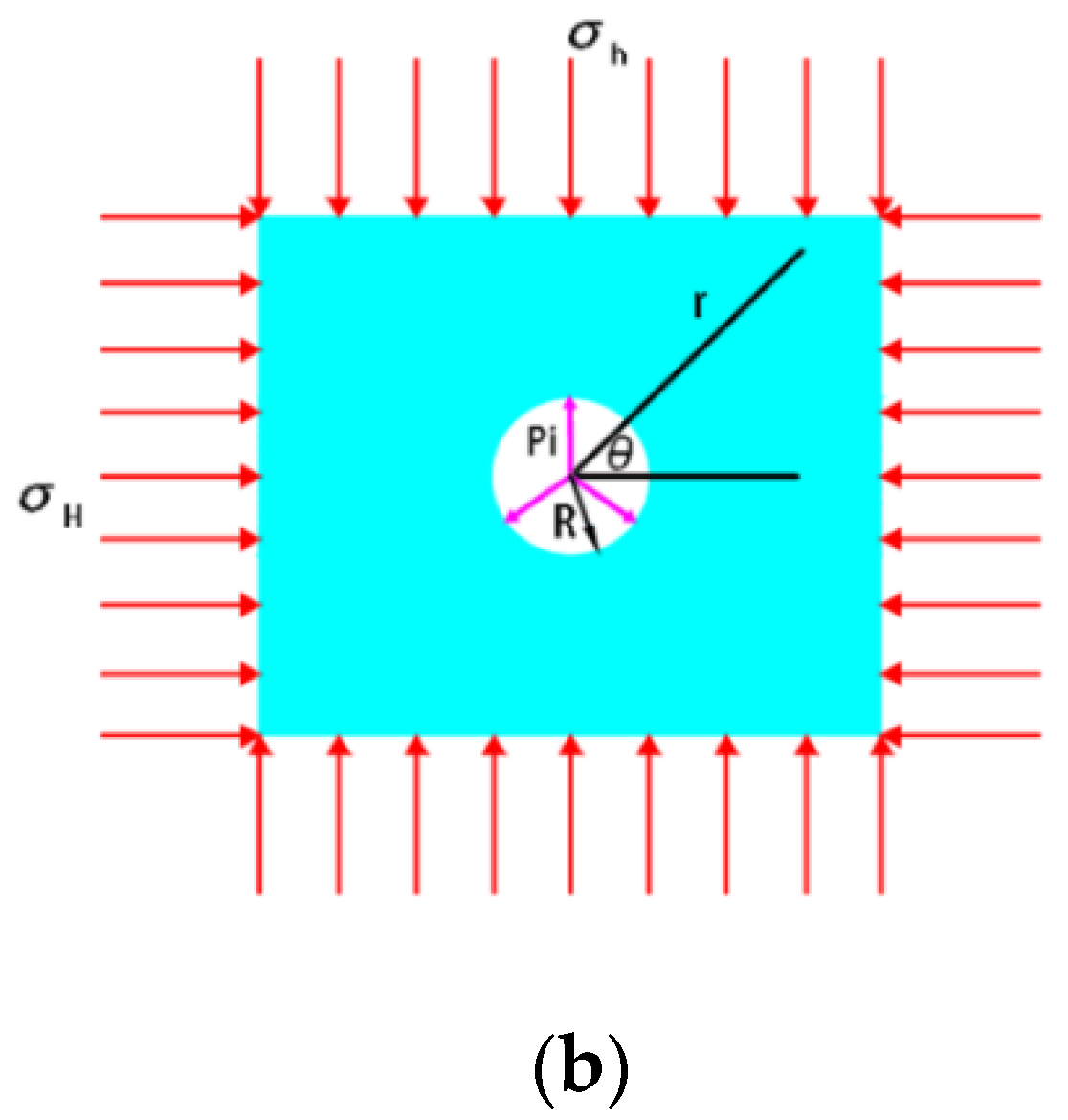
2.1. Stress Distribution around the Borehole Wall
2.2. Stability Analysis for an Unbroken Ice Borehole Wall
2.2.1. The Mogi–Coulomb Criterion
2.2.2. The Teardrop Criterion
2.2.3. The Derradji-Aouat Criterion
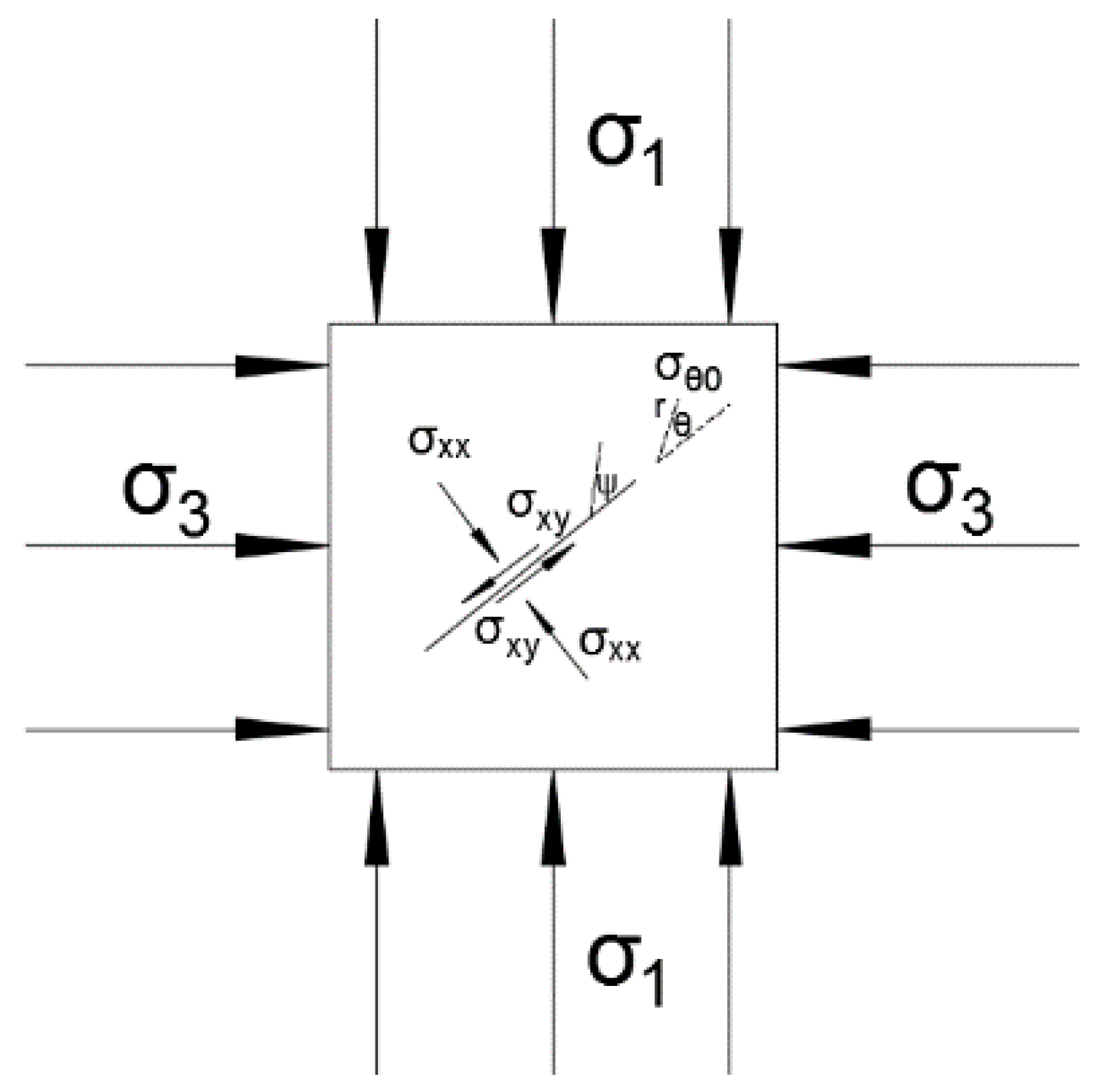
2.3. Stability Analysis for a Fissured Ice Borehole Wall
2.3.1. Instability Criterion
2.3.2. Crack States on the Borehole Wall: Open or Closed?
2.3.3. Critical Drilling Fluid Pressure
3. Results and Discussion
3.1. Critical Pressure for an Unbroken Ice Borehole Wall
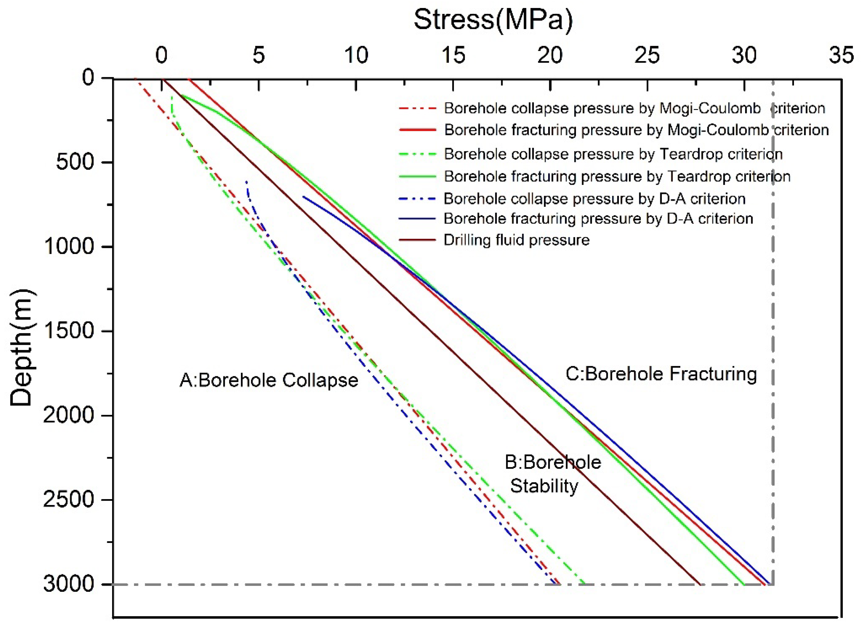
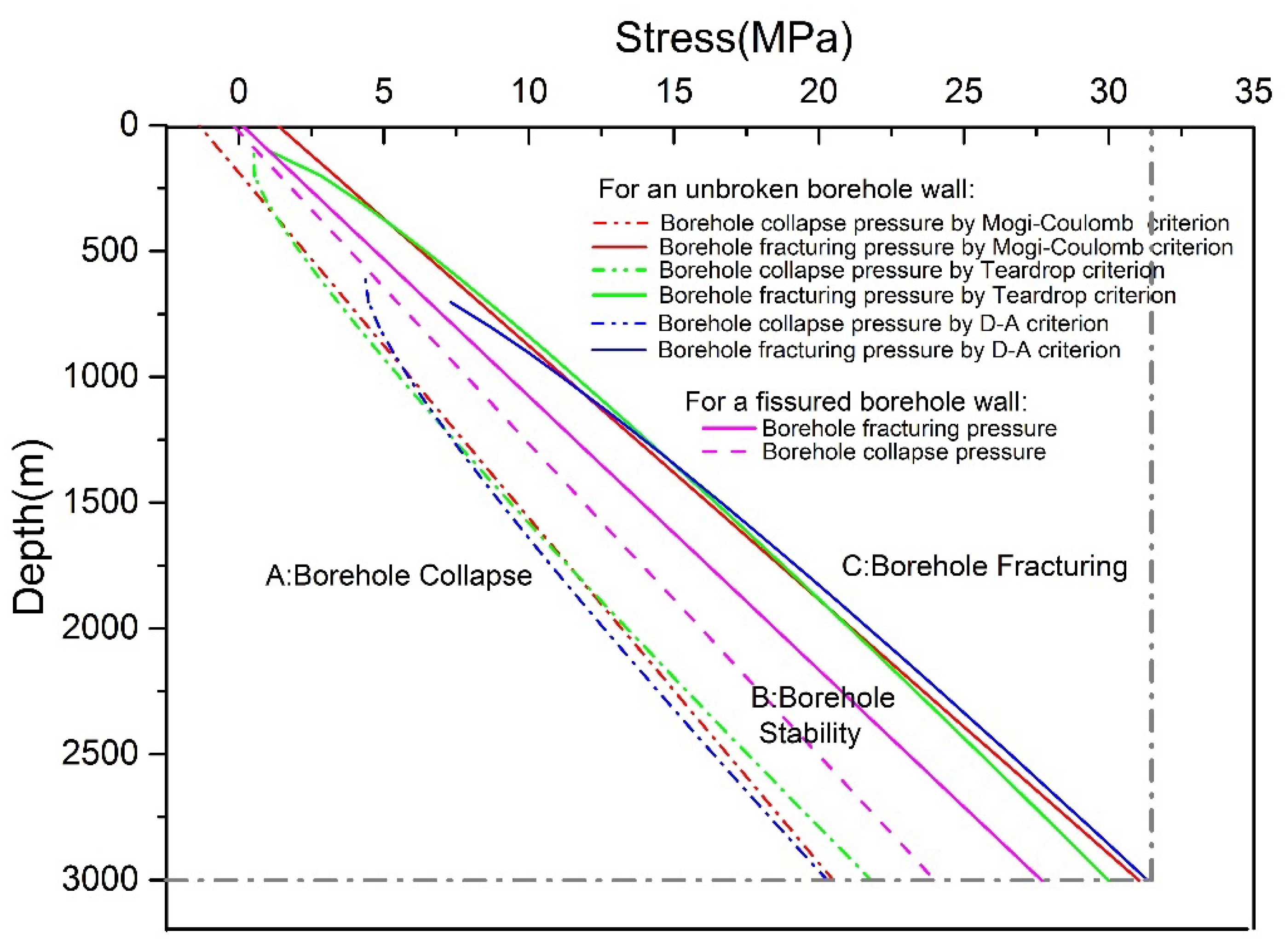
3.1.1. Study A: Comparison of the Critical Borehole Fracturing and Collapse Pressure between the Three Failure Criteria
- The drilling fluid pressure curve passes through the borehole stability area, which means that no collapse or fracturing occurs on the whole borehole wall;
- When ice borehole depth is 600–1200 m, the window for the safety drilling fluid pressure with a stable borehole wall is the widest when calculated by the teardrop criterion and is the most conservative when calculated by the Derradji-Aouat criterion. With depth increases, the safety drilling fluid pressure window as calculated by the Derradji-Aouat criterion reaches the maximum. Comparatively speaking, the Mogi–Coulomb criterion is the most stable failure criterion and is the most conservative in the deep range of 1200–1750 m.
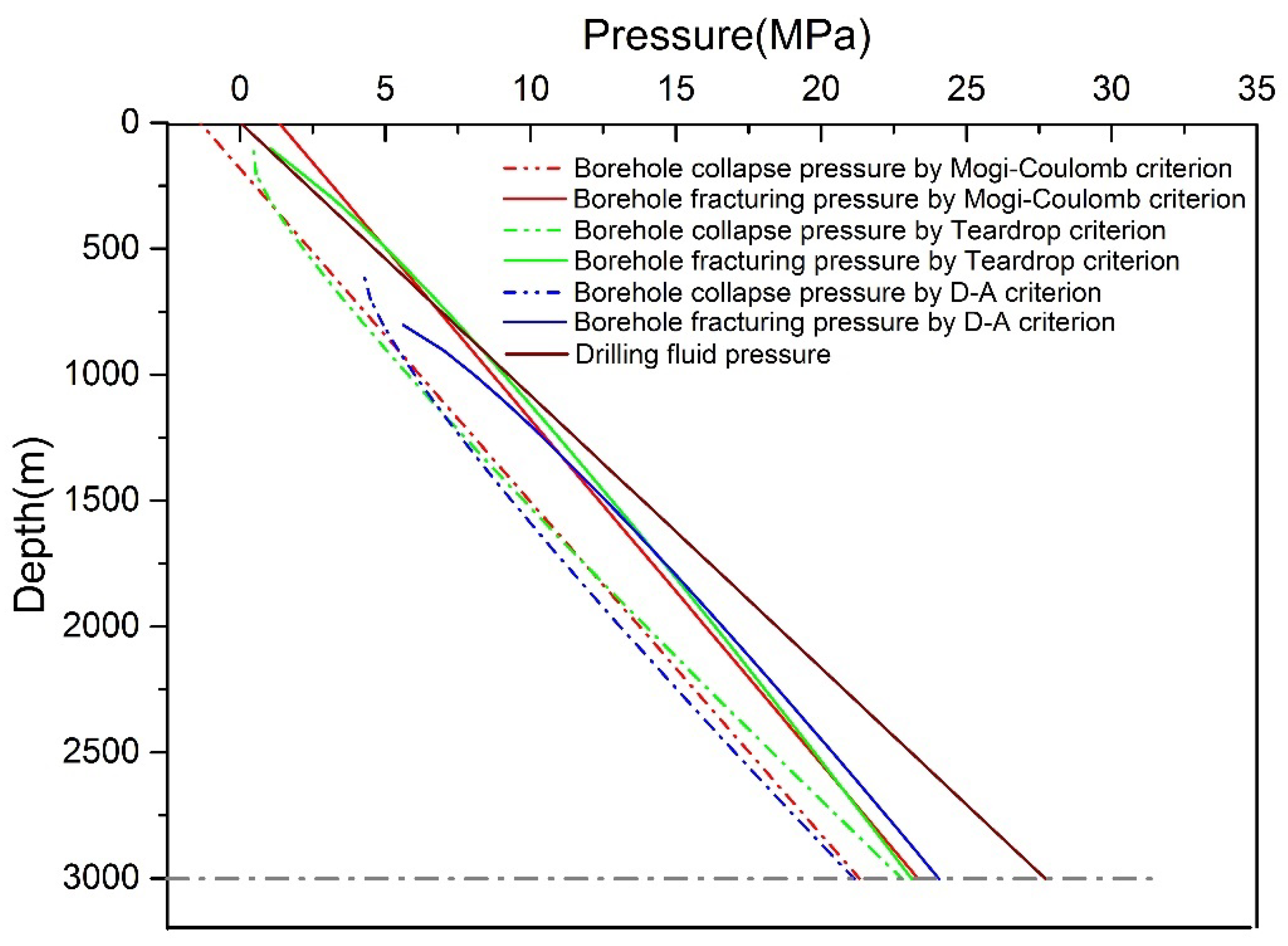
3.1.2. Study B: Influence of a Horizontal Stress Differential on Critical Borehole Fracturing and Collapse Pressure Considering Three Failure Criteria
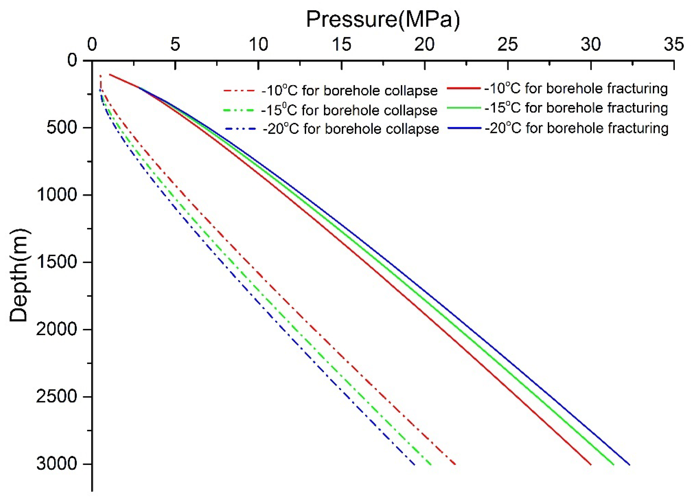
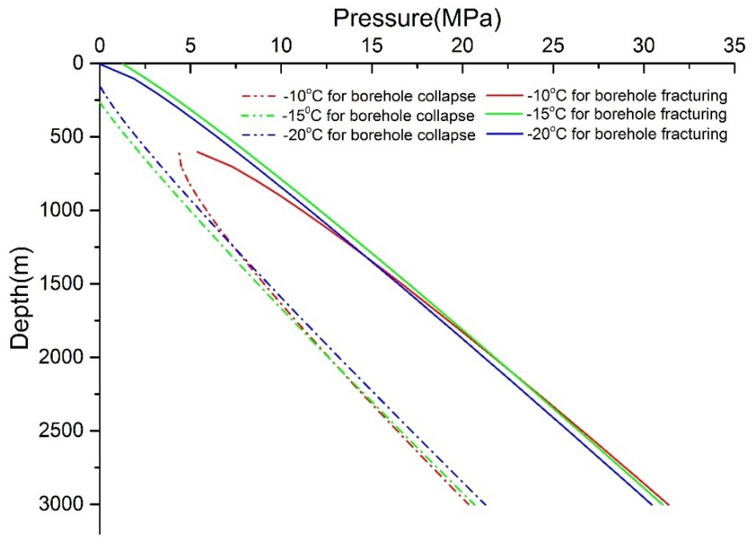
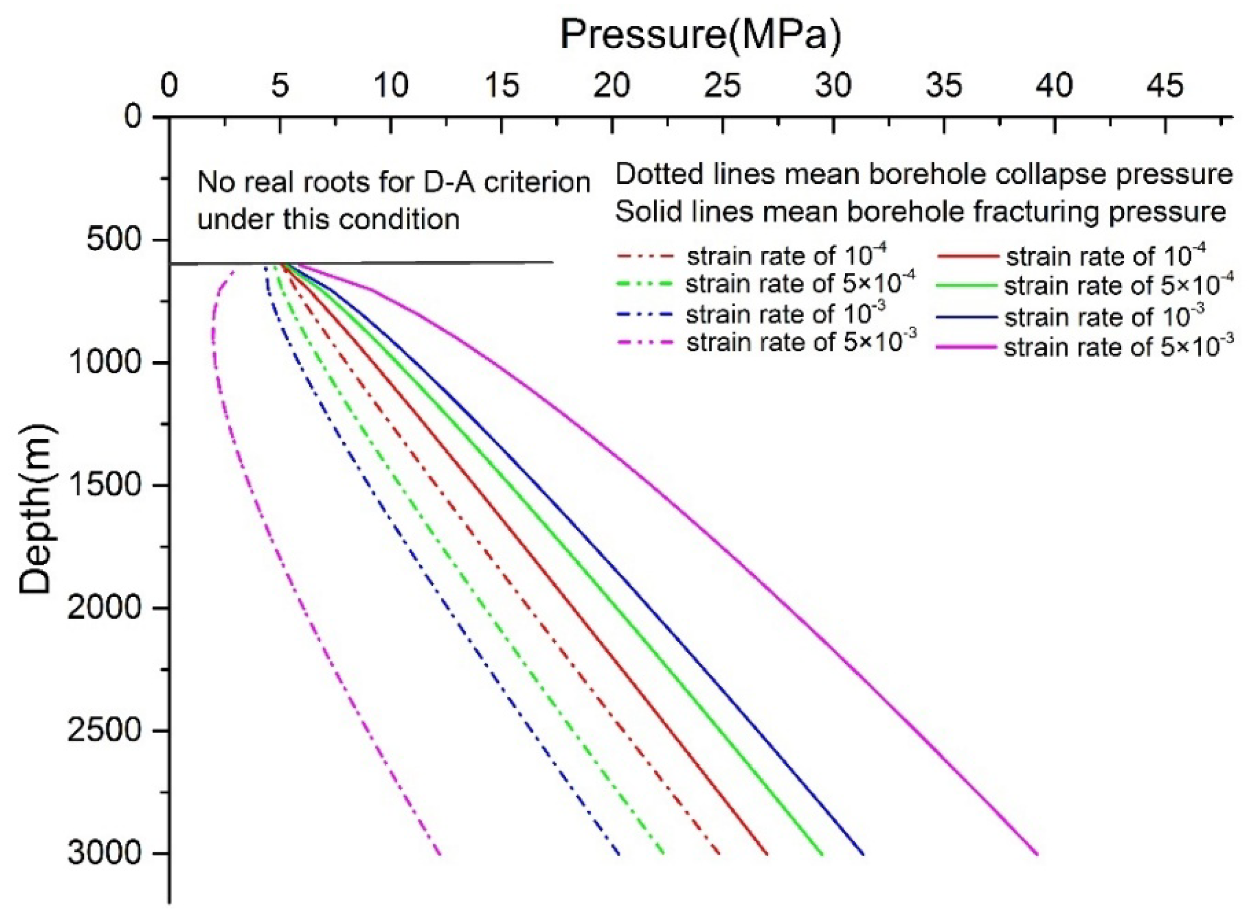
3.1.3. Study C: Influence of Temperature and Strain Rate on Critical Borehole Fracturing and Collapse Pressure
3.2. Critical Pressure for a Fissured Ice Borehole Wall
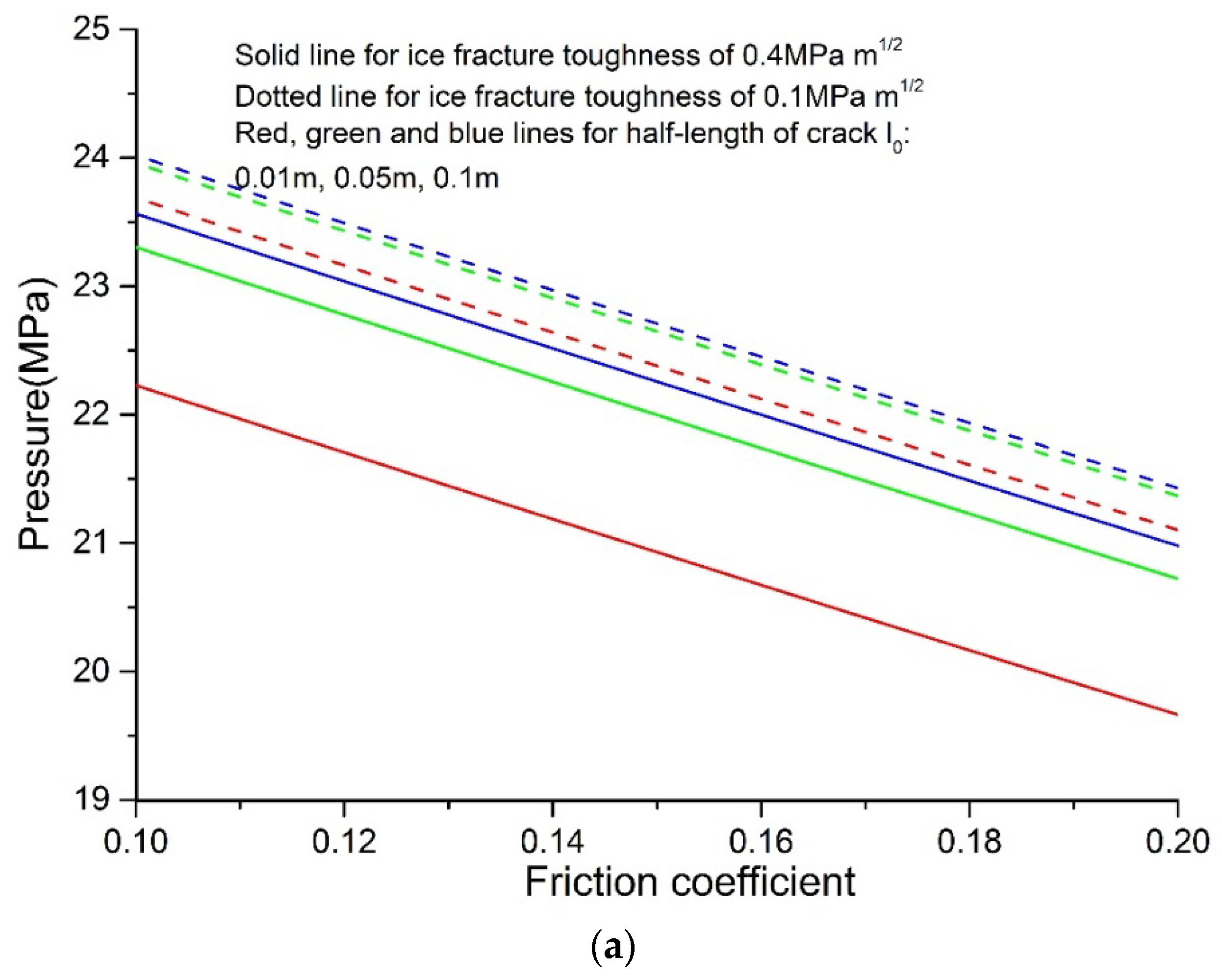
- For borehole collapse, the critical pressure decreases with an increase of the friction coefficient; a higher value of ice fracturing toughness and a longer fracture length on the borehole wall need a higher collapse pressure for borehole stability. The factor of the friction coefficient has the biggest impact on the results.
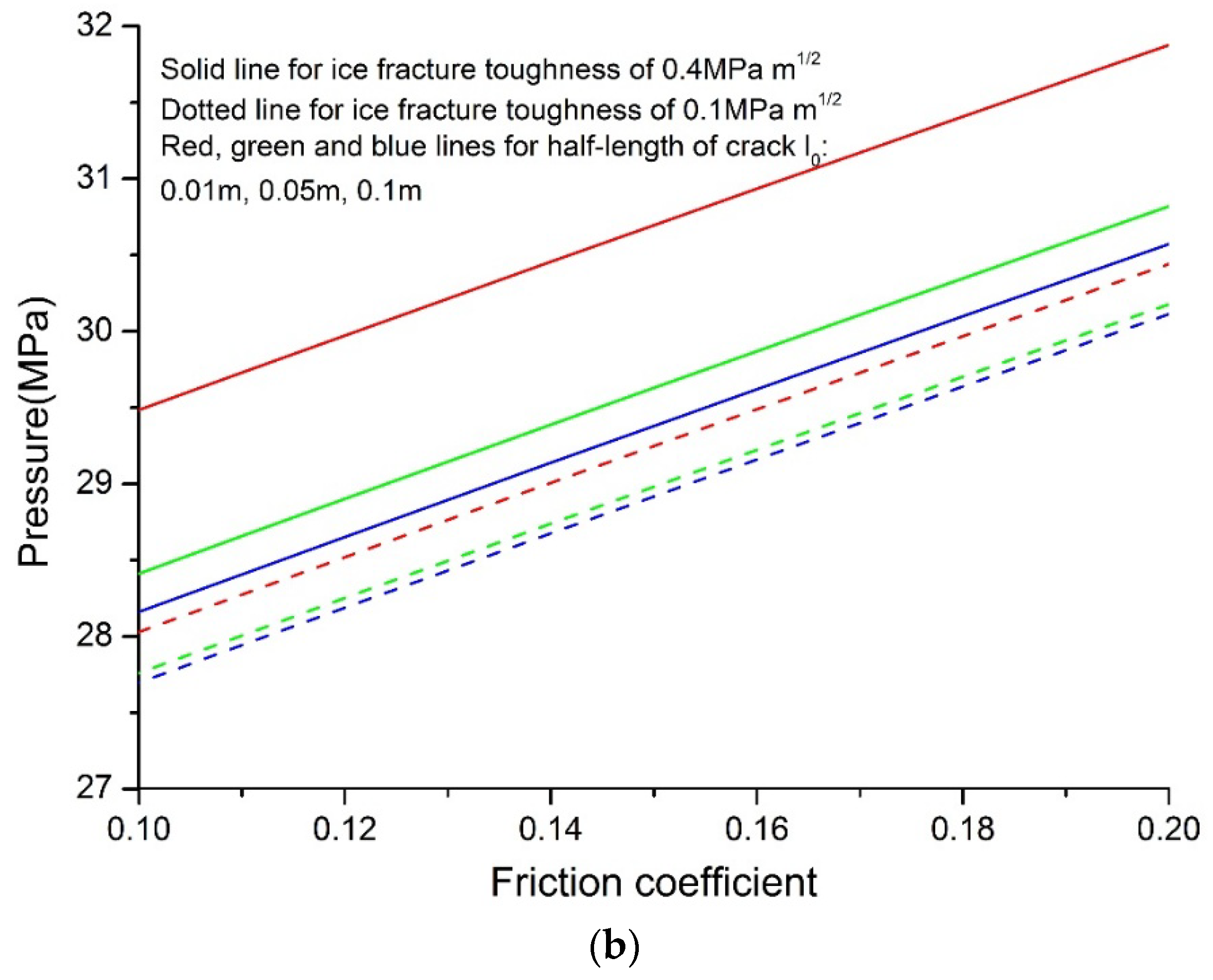
- For borehole fracturing, the variation trend of the critical pressure is contrary to the collapse pressure, and the pressure increases with a higher friction coefficient, a higher ice fracture toughness, and a shorter fracture length. Similarly, the factor of the friction coefficient exerts a tremendous influence on the critical pressure.
3.3. Discussion on Practical Applications and Suggestions
4. Conclusions
- For an unbroken borehole wall, no borehole collapse or fracturing occurred under the common drilling fluid pressure. At the same time, an analysis of factors influencing the borehole stability showed that: (1) a larger horizontal stress differential would increase the borehole instability. When drilling in high ice flow areas on ice sheets or glaciers, necessary measures of reducing the drilling fluid density should be taken to keep the borehole stable; (2) The effect of the strain rate on borehole stability showed that the safety drilling fluid pressure window became wider with the increase of the strain rate on the borehole wall, under the Derradji-Aouat criterion. When comparing such a window with the results calculated by the other two criteria, an approximate result came up at a strain rate of around 10−3/s. (3) As for the temperature, such a window as calculated by Derradji-Aouat can show an interaction between the strain rate and the temperature better than the teardrop criterion.
- For a fissured borehole wall, the ice friction coefficient played the most important role in determining the borehole critical failure pressure, compared with the factors of fracture toughness and fracture length. The borehole became more stable under the condition of shorter fracture length and higher friction coefficient and fracture toughness. At the same time, a maximum reduction of about 55% of the safety drilling fluid pressure window was calculated when comparing the fissured borehole wall to the unbroken one. In the actual application, we should pay more attention to the state of the ice core’s integrity. If we drilled into a fissured ice layer, the necessary measures of adjusting the drilling fluid density should be taken, to ensure that the borehole pressure is within the calculated safety pressure window.
Author Contributions
Funding
Acknowledgments
Conflicts of Interest
References
- Chen, X.; Tan, C.P.; Detournay, C. A study on wellbore stability in fractured rock masses with impact of mud infiltration. J. Pet. Sci. Eng. 2003, 38, 145–154. [Google Scholar] [CrossRef]
- Hashemi, S.S.; Taheri, A.; Melkoumian, N. Shear failure analysis of a shallow depth unsupported borehole drilled through poorly cemented granular rock. Eng. Geol. 2014, 183, 39–52. [Google Scholar] [CrossRef]
- Lee, H.; Ong, S.H.; Azeemuddin, M.; Goodman, H. A wellbore stability model for formations with anisotropic rock strengths. J. Pet. Sci. Eng. 2012, 96–97, 109–119. [Google Scholar] [CrossRef]
- Gholami, R.; Moradzadeh, A.; Rasouli, V.; Hanachi, J. Practical application of failure criteria in determining safe mud weight windows in drilling operations. J. Rock Mech. Geotech. Eng. 2014, 6, 13–25. [Google Scholar] [CrossRef]
- Al-Ajmi, A.M.; Zimmerman, R.W. Stability analysis of vertical boreholes using the Mogi–Coulomb failure criterion. Int. J. Rock Mech. Min. 2006, 43, 1200–1211. [Google Scholar] [CrossRef]
- Hobbs, D.W. The Strength and the Stress-Strain Characteristics of Coal in Triaxial Compression. J. Geol. 1964, 72, 214–231. [Google Scholar] [CrossRef]
- Handin, J.; Heard, H.C.; Magouirk, J.N. Effects of the intermediate principal stress on the failure of limestone, dolomite, and glass at different temperatures and strain rates. J. Geophys. Res. 1967, 72, 611–640. [Google Scholar] [CrossRef]
- Mogi, K. Fracture and Flow of Rocks under High Triaxial Compression. J. Geophys. Res. 1971, 76, 1255–1269. [Google Scholar] [CrossRef]
- Hoek, E.; Brown, E.T. Practical estimates of rock mass strength. Int. J. Rock Mech. Min. 1997, 34, 1165–1186. [Google Scholar] [CrossRef]
- Franklin, J.A. Triaxial strength of rock materials. Rock Mech. 1971, 3, 86–98. [Google Scholar] [CrossRef]
- Colmenares, L.B.; Zoback, M.D. A statistical evaluation of intact rock failure criteria constrained by polyaxial test data for five different rocks. Int. J. Rock Mech. Min. 2002, 39, 695–729. [Google Scholar] [CrossRef]
- Haimson, B.C.; Chang, C.D. True triaxial strength of the KTB amphibolite under borehole wall conditions and its use to estimate the maximum horizontal in situ stress. J. Geophys. Res. 2002, 107, ETG 15-11–ETG 15-14. [Google Scholar] [CrossRef]
- Aadnoy, B.S.; Froitland, T.S. Stability of adjacent boreholes. J. Pet. Sci. Eng. 1991, 6, 37–43. [Google Scholar] [CrossRef]
- Fuh, G.F.; Whitfill, D.L.; Schuh, P.R. Use of borehole stability analysis for successful drilling of high-angle hole. In Proceedings of the IADC/SPE Drilling Conference, Dallas, TX, USA, 28 February–2 March 1988. [Google Scholar]
- McLean, M.R.; Addis, M.A. Wellbore stability: The effect of strength criteria on mud weight recommendations. In Proceedings of the 65th Annual Technical Conference and Exhibition of SPE, New Orleans, LA, USA, 23–26 September 1990. [Google Scholar]
- Al-Ajmi, A.M.; Zimmerman, R.W. Relation between the Mogi and the Coulomb failure criteria. Int. J. Rock Mech. Min. 2005, 42, 431–439. [Google Scholar] [CrossRef]
- Vernik, L.; Zoback, M.D. Strength anisotropy in crystalline rock: Implications for assessment of in situ stresses from wellbore breakouts. In Proceedings of the 31st US Symposium on Rock Mechanics Contributions and Challenges, Rotterdam, The Netherlands, 18–20 June 1990. [Google Scholar]
- Liang, C.; Chen, M.; Jin, Y.; Lu, Y.H. Wellbore stability model for shale gas reservoir considering the coupling of multi-weakness planes and porous flow. J. Nat. Gas Sci. Eng. 2014, 21, 364–378. [Google Scholar] [CrossRef]
- Ma, T.S.; Chen, P. A wellbore stability analysis model with chemical-mechanical coupling for shale gas reservoirs. J. Nat. Gas Sci. Eng. 2015, 26, 72–98. [Google Scholar] [CrossRef]
- Karatela, E.; Taheri, A.; Xu, C.S.; Stevenson, G. Study on effect of in-situ stress ratio and discontinuities orientation on borehole stability in heavily fractured rocks using discrete element method. J. Petrol. Sci. Eng. 2016, 139, 94–103. [Google Scholar] [CrossRef]
- Talalay, P.; Fan, X.P.; Xu, H.W.; Yu, D.H.; Han, L.L.; Han, J.J.; Sun, Y.H. Drilling fluid technology in ice sheets: Hydrostatic pressure and borehole closure considerations. Cold Reg. Sci. Technol. 2014, 98, 47–54. [Google Scholar] [CrossRef]
- Fujii, Y.; Azuma, N.; Tanaka, Y.; Nakayama, Y.; Kameda, T.; Shinbori, K.; Katagiri, K.; Fujita, S.; Takahashi, A.; Kawada, K. Deep ice core drilling to 2503 m depth at Dome Fuji, Antarctica. Mem. Natl. Inst. Polar Res. Spec. Issue 2002, 56, 103–116. [Google Scholar]
- Lyle, H.B.; Gundestrup, N.S. Resurvey of Bore Hole at Dye 3, South Greenland. J. Glaciol. 2017, 34, 178–182. [Google Scholar] [CrossRef]
- Chen, C.; Zhang, H.; Liu, S.Y.; Jin, C.C.; Chen, Y.; Zhang, N. Hydraulic fracturing in ice boreholes: Theory and tests. Polar Sci. 2018, in press. [Google Scholar] [CrossRef]
- Nadreau, J.P.; Nawwar, A.M.; Wang, Y.S. Triaxial testing of freshwater ice at low confining pressures. J. Offshore Mech. Arct. 1991, 113, 260–265. [Google Scholar] [CrossRef]
- Derradji-Aouat, A. Multi-surface failure criterion for saline ice in the brittle regime. Cold Reg. Sci. Technol. 2003, 36, 47–70. [Google Scholar] [CrossRef]
- Westergaard, H.M. Plastic state of stress around a deep well. J. Boston Soc. Civ. Eng. 1940, 27, 1–5. [Google Scholar]
- Gnirk, P.F. The Mechanical Behavior of Uncased Wellbores Situated in Elastic/Plastic Media under Hydrostatic Stress. Soc. Pet. Eng. J. 1972, 12, 49–59. [Google Scholar] [CrossRef]
- Mitchell, R.F.; Goodman, M.A.; Wood, E.T. Borehole stresses: Plasticity and the drilled hole effect. In Proceedings of the IADC/SPE Drilling Conference, New Orleans, LA, USA, 15–18 March 1987. [Google Scholar]
- Anthony, J.L.; Crook, J.Y. Development of an orthotropic 3D elastoplastic material model for shale. In Proceedings of the SPE/ISRM Rock Mechanics Conference, Irving, TX, USA, 20–23 October 2002. [Google Scholar]
- Ashby, M.F.; Hallam, S.D. The failure of brittle solids containing small cracks under compressive stress states. Acta Metall. 1986, 34, 497–510. [Google Scholar] [CrossRef]
- Lin, P. Brittle Failure Behavior of Media Containing Cracks and Holes. Ph.D. Thesis, Northeastern University, Shenyang, China, 2 February 2002. [Google Scholar]
- Zhen, G. Research on the Damage and Fracture Meehanism of Wellbore Stability. Ph.D. Thesis, Harbin Engineering University, Harbin, China, 20 May 2005. [Google Scholar]
- Hooke, R.L. Principles of Glacier Mechanics, 2nd ed.; Cambridge University Press: Cambridge, UK, 2005. [Google Scholar]
- Shan, R.; Bai, Y.; Huang, P.; Song, Y.; Guo, X. Experimental Research on Failure Criteria of Freshwater Ice under Triaxial Compressive Stress. Chin. J. Theor. Appl. Mech. 2017, 49, 467–477. [Google Scholar]
- Rist, M.A.; Murrell, S.A.F. Ice triaxial deformation and fracture. J. Glaciol. 1994, 40, 305–318. [Google Scholar] [CrossRef]
- Gagnon, R.E.; Gammon, P.H. Triaxial experiments on iceberg and glacier ice. J. Glaciol. 1995, 41, 528–540. [Google Scholar] [CrossRef]
- Duval, P. Creep and Fracture of Ice; Cambridge University Press: Cambridge, UK, 2009. [Google Scholar]
- Beeman, M.; Durham, W.B.; Kirby, S.H. Friction of ice. J. Geophys. Res. Solid Earth 1988, 93, 7625–7633. [Google Scholar] [CrossRef]
- Montagnat, M.; Schulson, E.M. On friction and surface cracking during sliding of ice on ice. J. Glaciol. 2003, 49, 391–396. [Google Scholar] [CrossRef]
- Kietzig, A.M.; Hatzikiriakos, S.G.; Englezos, P. Physics of ice friction. J. Appl. Phys. 2010, 107, 4. [Google Scholar] [CrossRef]
- Schulson, E.M.; Fortt, A.L.; Iliescu, D.; Renshaw, C.E. On the role of frictional sliding in the compressive fracture of ice and granite: Terminal vs. post-terminal failure. Acta Mater. 2006, 54, 3923–3932. [Google Scholar] [CrossRef]


| Circumstances | Borehole Fracturing Pressure | |
|---|---|---|
| 1 | ||
| 2 | ||
| 3 | ||
| where: , | ||
| Circumstances | Borehole Collapse Pressure | |
|---|---|---|
| 1 | ||
| 2 | ||
| 3 | ||
| where: , | ||
| Circumstances | Borehole Fracturing Pressure | |
|---|---|---|
| 1 | ||
| 2 | ||
| 3 | ||
| where: , | ||
| Circumstances | Borehole Collapse Pressure | |
|---|---|---|
| 1 | ||
| 2 | ||
| 3 | ||
| where: , | ||
| Circumstances | Borehole Fracturing Pressure | |
|---|---|---|
| 1 | ||
| 2 | ||
| 3 | ||
| where: | ||
| Circumstances | Borehole Collapse Pressure | |
|---|---|---|
| 1 | ||
| 2 | ||
| 3 | ||
| where: , | ||
| Circumstances | Borehole Fracturing Pressure | |
|---|---|---|
| 1 | ||
| 2 | ||
| 3 | ||
| where: , is the ice fracture toughness, is the friction coefficient between cracks, is the half-length of the crack. | ||
| Circumstances | Borehole Collapse Pressure | |
|---|---|---|
| 1 | ||
| 2 | ||
| 3 | ||
| where: , is the ice fracture toughness, is the friction coefficient between cracks, is the half-length of the crack. | ||
| Parameter | Value | Unit |
|---|---|---|
| Cohesion, | 1.204 | MPa |
| Internal friction angle, | 9.228 | angle |
| Tensile strength, | 0.81 | MPa |
| Pressure phase transition, | 115 | MPa |
| Strain rate, | 10−3 | /s |
| Poisson’s ratio, | 0.31 | |
| Long axis of the ellipse, | 55.0 | MPa |
© 2018 by the authors. Licensee MDPI, Basel, Switzerland. This article is an open access article distributed under the terms and conditions of the Creative Commons Attribution (CC BY) license (http://creativecommons.org/licenses/by/4.0/).
Share and Cite
Zhang, H.; Pan, D.; Zhai, L.; Zhang, Y.; Chen, C. Stability Analysis in Determining Safety Drilling Fluid Pressure Windows in Ice Drilling Boreholes. Energies 2018, 11, 3378. https://doi.org/10.3390/en11123378
Zhang H, Pan D, Zhai L, Zhang Y, Chen C. Stability Analysis in Determining Safety Drilling Fluid Pressure Windows in Ice Drilling Boreholes. Energies. 2018; 11(12):3378. https://doi.org/10.3390/en11123378
Chicago/Turabian StyleZhang, Han, Dongbin Pan, Lianghao Zhai, Ying Zhang, and Chen Chen. 2018. "Stability Analysis in Determining Safety Drilling Fluid Pressure Windows in Ice Drilling Boreholes" Energies 11, no. 12: 3378. https://doi.org/10.3390/en11123378
APA StyleZhang, H., Pan, D., Zhai, L., Zhang, Y., & Chen, C. (2018). Stability Analysis in Determining Safety Drilling Fluid Pressure Windows in Ice Drilling Boreholes. Energies, 11(12), 3378. https://doi.org/10.3390/en11123378