Optimal Design of a High-Speed Single-Phase Flux Reversal Motor for Vacuum Cleaners


Abstract
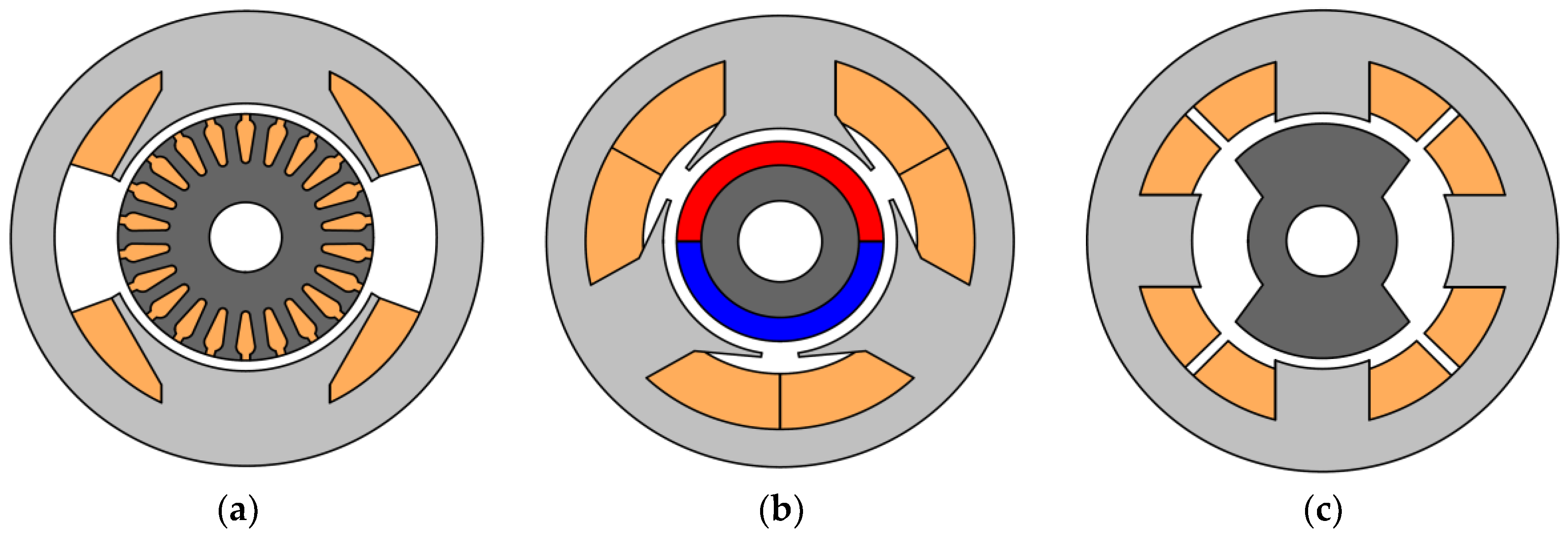
:1. Introduction
- The FRM is more reliable and its lifetime is longer, as it has no collector assembly and no brushes;
- The heat removal from the rotor is not required because the rotor does not contain any heating elements such as coils or a collector. This also increases the reliability of the rotor bearings;
- The toothed rotor production is very simple and not necessarily required. Its only active part is a magnetic core made of laminated steel;
- The FRM mass is much less than that of the AC commutator motor with brushes;
- The efficiency of the FRM is higher than that of the AC commutator motor with brushes.
- The toothed rotor of the FRM is simpler and more reliable, without permanent magnets;
- High-speed synchronous motors with magnets on the rotor often have an additional retaining ring on the rotor to fix the magnets;
- The FRM rotor is simpler, more reliable, and does not require balancing.
- Only half a period is used to generate torque in the SRM, while the FRM can do it for almost an entire period, which increases the efficiency as well as the specific torque and power;
- The SRM has open stator slots [14] and only about half the stator surface is used, which decreases the efficiency as well as the specific torque and power;
- Almost half of the electrical energy received by the SRM returns to its inverter and does not transform to mechanical energy, which increases the winding current as well as increasing the inverter cost and size;
- The single-phase inverter (control circuit of the motor) for the FRM is simpler and cheaper compared to the inverter for the two-phase SRM.
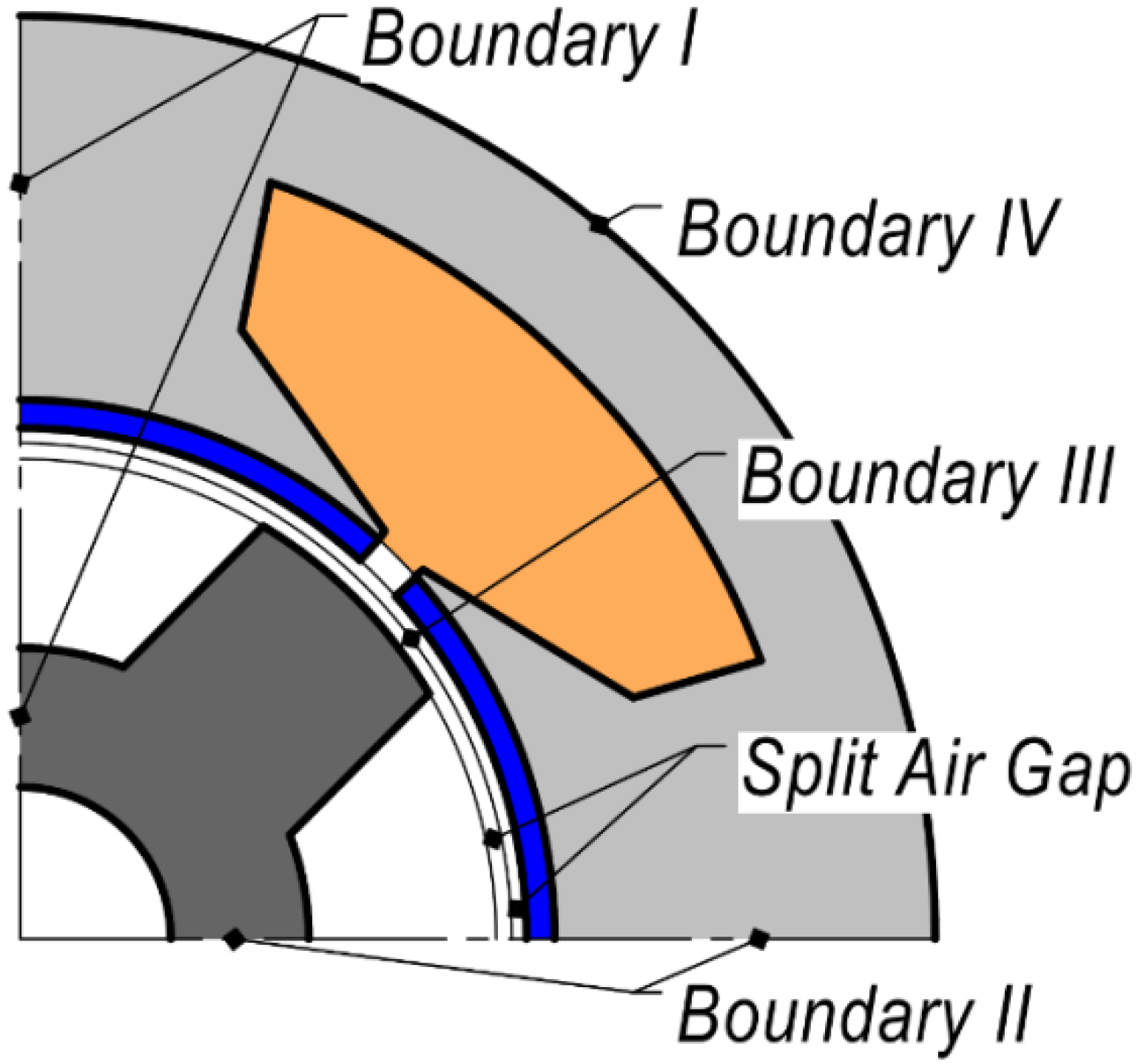
2. Brief Description of the New FRM Mathematical Model
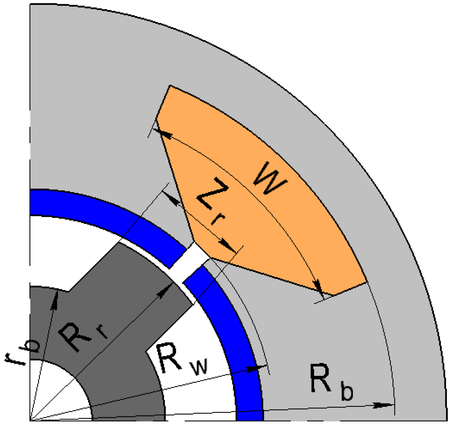
3. The FRM Optimization Criteria and Procedure
- Outer rotor radius Rr;
- Slot bottom radius Rb;
- Slot width W;
- Rotor tooth width Zr;
- Rotor bottom radius rb;
- Stator winding coil number N.
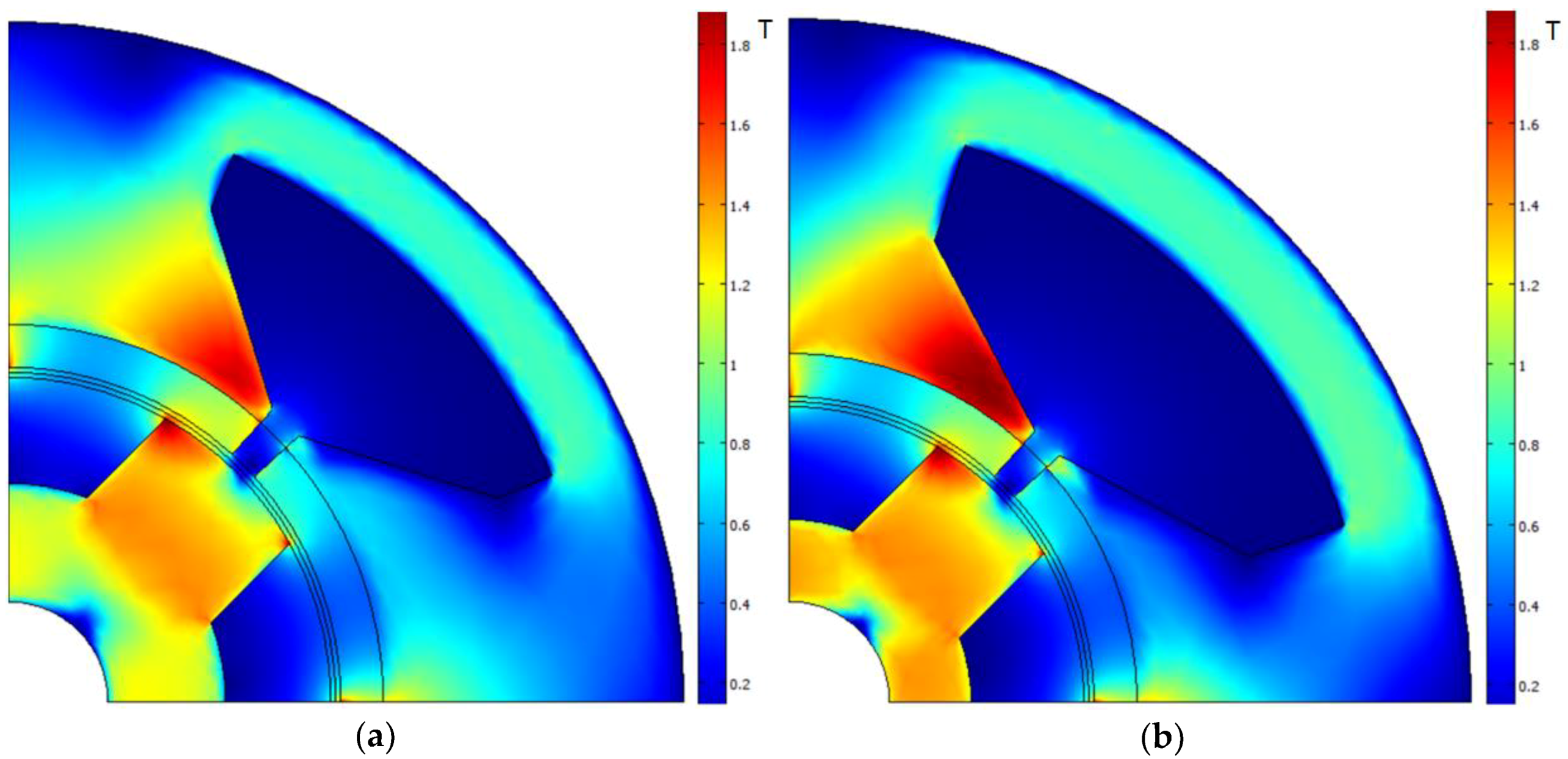
4. The Results of the Optimization
5. Conclusions
Author Contributions
Funding
Conflicts of Interest
References
- Abele, E.; Anderl, R.; Birkhofer, H. Environmentally-Friendly Product Development: Methods and Tools; Springer: London, UK, 2005. [Google Scholar] [CrossRef]
- Bentouati, S.; Zhu, Z.Q.; Howe, D. Permanent magnet brushless DC motors for consumer products. In Proceedings of the Ninth International Conference on Electrical Machines and Drives (Conf. Publ. No. 468), Canterbury, UK, 1–3 September 1999; pp. 118–122. [Google Scholar] [CrossRef]
- Lukman, G.; Hieu, P.; Jeong, K.; Ahn, J. Characteristics analysis and comparison of high-speed 4/2 and hybrid 4/4 poles switched reluctance motor. Machines 2018, 6, 4. [Google Scholar] [CrossRef]
- Syed, Q.; Kurtovic, H.; Hahn, I. New single-phase flux switching axial flux permanent magnet motor. IEEE Trans. Magn. 2017, 53, 1–5. [Google Scholar] [CrossRef]
- Zhang, Z.; Tang, X.; Wang, D.; Yang, Y.; Wang, X. Novel rotor design for single-phase flux switching motor. IEEE Trans. Energy Convers. 2018, 33, 354–361. [Google Scholar] [CrossRef]
- Jeong, K.; Ahn, J. Design and characteristics analysis of a novel single-phase hybrid srm for blender application. J. Electr. Eng. Technol. 2018, 13, 1996–2003. [Google Scholar] [CrossRef]
- Dmitrievskii, V.; Prakht, V.; Pozdeev, A.; Klimarev, V.; Mikhalitsyn, A. Angular grinder with new flux reversal motor. In Proceedings of the 18th International Conference on Electrical Machines and Systems (ICEMS), Pattaya, Thailand, 25–28 October 2015; pp. 1366–1371. [Google Scholar] [CrossRef]
- Shi, J.T.; Zhu, Z.Q.; Wu, D.; Liu, X. Comparative study of synchronous machines having permanent magnets in stator. Electr. Power Syst. Res. 2016, 133, 304–312. [Google Scholar] [CrossRef]
- Upgrade for Life, Powerful Cyclone; VC01-1708, Catalogue; Hitachi, Ltd.: Tokyo, Japan, 2017.
- Code 790 Family 183 mm (7,2″) Diameter 1800 W Blower. Available online: http://donar.messe.de/exhibitor/hannovermesse/2017/T813330/790-blower-data-sheet-eng-490247.pdf (accessed on 18 November 2018).
- Tezcan, M.M.; Çanakoğlu, A.I.; Yetgin, A.G.; Gün, A.; Cevher, B.; Turan, M. Analysis of one phase special electrical machines using finite element method. In Proceedings of the International Conference on Electromechanical and Power Systems (SIELMEN 2017), Iasi, Romania, 11–13 October 2017; pp. 113–118. [Google Scholar]
- Kamalakannan, D.; Singh, N.; Karthi, M.; Narayanan, V.; Ramanathan, N. Design and development of DC powered BLDC motor for Mixer-Grinder application. In Proceedings of the First International Conference on Sustainable Green Buildings and Communities (SGBC 2016), Chennai, India, 18–20 December 2016; pp. 1–6. [Google Scholar]
- Hannon, B.; Sergeant, P.; Dupré, L. Evaluation of the torque in high-speed PMSMs with a shielding cylinder and BLDC control. IEEE Trans. Magn. 2018, 54, 1–8. [Google Scholar] [CrossRef]
- Hieu, P.; Lee, D.; Ahn, J. Design of a high speed 4/2 switched reluctance motor for blender application. In Proceedings of the IEEE Transportation Electrification Conference and Expo, Asia-Pacific (ITEC Asia-Pacific 2017), Harbin, China, 7–10 August 2017; pp. 1–5. [Google Scholar] [CrossRef]
- Li, D.; Gao, Y.; Qu, R.; Li, J.; Huo, Y.; Ding, H. Design and analysis of a flux reversal machine with evenly distributed permanent magnets. IEEE Trans. Ind. Appl. 2018, 54, 172–183. [Google Scholar] [CrossRef]
- Zhu, X.; Hua, W. An improved configuration for cogging torque reduction in flux-reversal permanent magnet machines. IEEE Trans. Magn. 2017, 53, 1–6. [Google Scholar] [CrossRef]
- Vidhya, B.; Srinivas, K. Effect of stator permanent magnet thickness and rotor geometry modifications on the minimization of cogging torque of a flux reversal machine. Turk. J. Electr. Eng. Comput. Sci. 2017, 25, 4907–4922. [Google Scholar] [CrossRef]
- Deodhar, R.; Andersson, S.; Boldea, I.; Miller, T. The flux-reversal machine: A new brushless doubly-salient permanent-magnet machine. IEEE Trans. Ind. Appl. 1997, 3, 925–934. [Google Scholar] [CrossRef]
- Jang, K.B.; Won, S.H.; Kim, T.H.; Lee, J. Starting and high-speed driving of single-phase flux-reversal motor for vacuum cleaner. IEEE Trans. Magn. 2005, 41, 3967–3969. [Google Scholar] [CrossRef]
- Dmitrievskii, V.; Prakht, V. Single-Phase Electrical Machine. Available online: http://www.freepatent.ru/images/img_patents/2/2524/2524144/patent-2524144.pdf (accessed on 18 November 2018).
- Rotating Electrical Machines—Part 30-2: Efficiency Classes of Variable Speed AC Motors (IE-Code). Available online: https://www.iec.ch/dyn/www/f?p=103:52:0::::FSP_ORG_ID,FSP_DOC_ID,FSP_DOC_PIECE_ID:1221,151336,279593 (accessed on 18 November 2018).
- Gamba, M.; Pellegrino, G.; Armando, E.; Ferrari, S. Synchronous reluctance motor with concentrated windings for IE4 efficiency. In Proceedings of the Energy Conversion Congress and Exposition (ECCE 2017), Cincinnati, OH, USA, 1–5 October 2017; pp. 3905–3912. [Google Scholar] [CrossRef]
- Khelifa, M.; Mordjaoui, M.; Medoued, A. An inverse problem methodology for design and optimization of an interior permanent magnetic BLDC motor. Int. J. Hydrogen Energy 2017, 42, 17733–17740. [Google Scholar] [CrossRef]
- Bramerdorfer, G.; Tapia, J.; Pyrhönen, J.; Cavagnino, A. Modern electrical machine design optimization: Techniques, trends, and best practices. Trans. Ind. Electron. 2018, 65, 7672–7684. [Google Scholar] [CrossRef]
- Audet, C.; Tribes, C. Mesh-based Nelder-Mead algorithm for inequality constrained optimization. Comput. Optim. Appl. 2018, 71, 331–352. [Google Scholar] [CrossRef]
- Cai, L.; Li, P.; Luo, Q.; Zhai, P.; Zhang, Q. Geometry optimization of a segmented thermoelectric generator based on multi-parameter and nonlinear optimization method. J. Electron. Mater. 2017, 46, 1552–1566. [Google Scholar] [CrossRef]


| Mode № | 1 | 2 | 3 |
|---|---|---|---|
| Shaft power, % of the rated value | 12.5 | 37.5 | 100 |
| Rotational speed, % of the rated value | 50 | 75 | 100 |
| Torque, % of the rated value | 25 | 50 | 100 |
| Weight coefficient | 1 | 1 | 1 |
| Parameter | Before | After |
|---|---|---|
| Outer rotor radius Rr, mm | 12.9 | 11.7 |
| Slot bottom radius Rb, mm | 23.5 | 23 |
| Slot width W, degrees | 45 | 54.8 |
| Rotor tooth width Zr | 7 | 6 |
| Rotor bottom radius rb, mm | 8.7 | 7.2 |
| Stator winding coil number N | 50 | 64 |
| Parameter | Before | After |
|---|---|---|
| Mechanical power at the rated mode, W | 1500 | 1500 |
| Rated rotational speed, rpm | 28,000 | 28,000 |
| Outer diameter of the rotor, mm | 25.8 | 23.4 |
| Stator slot area, cm2 | 0.94 | 1.3 |
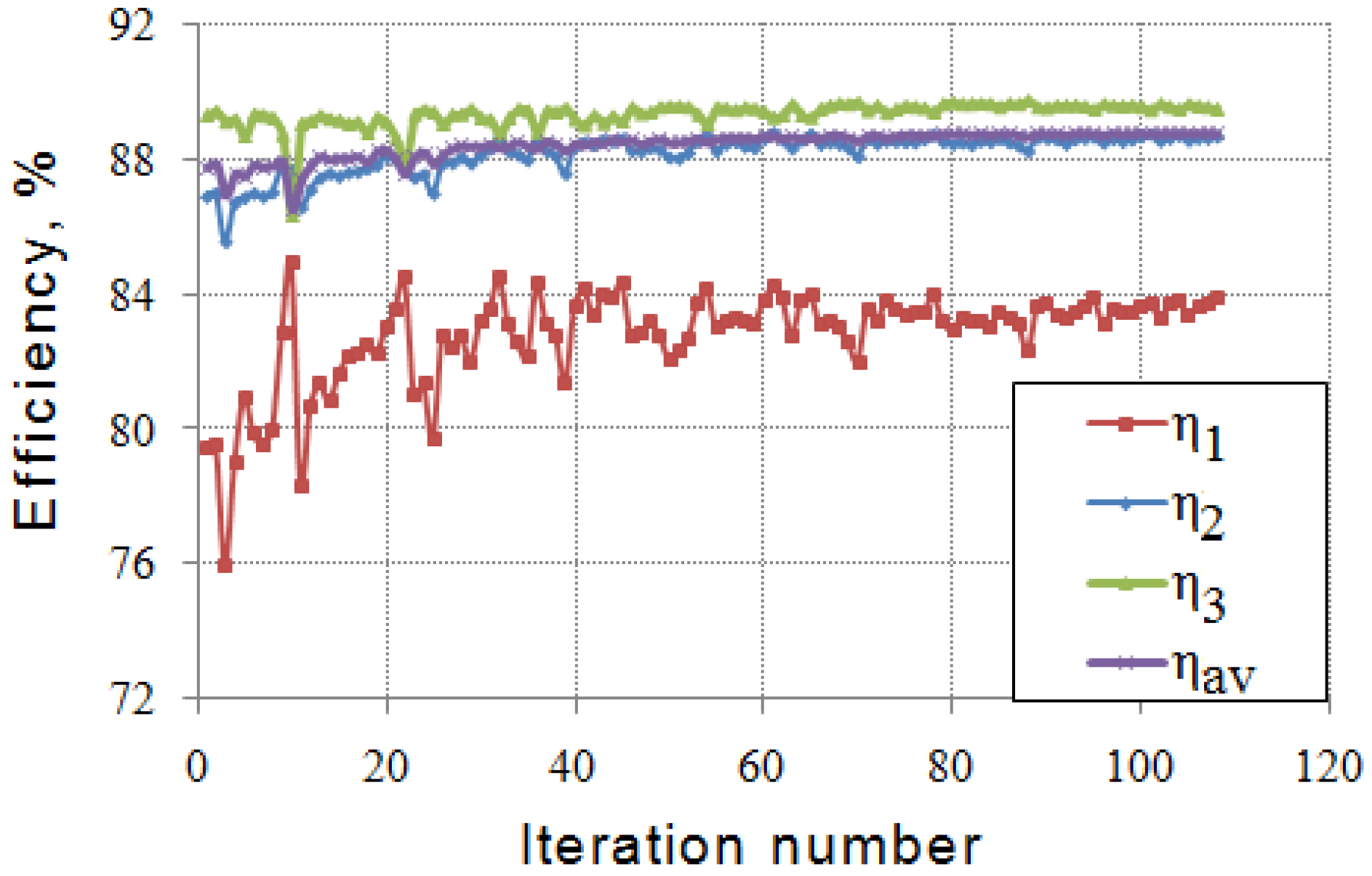
| η1, % | 79.5 | 83.6 |
| η2, % | 86.9 | 88.6 |
| η3, % | 89.3 | 89.6 |
| ηav, % | 87.8 | 88.8 |
| Torque ripple, % | 358 | 335 |
| Thickness of permanent magnets (PMs), mm | 1.7 | 1.7 |
| Thickness of sheets of the steel lamination (stator and rotor), mm | 0.5 | 0.5 |
| Steel grade | M330-50A | M330-50A |
| Weight of permanent magnets, g | 39 | 35.3 |
| Weight of stator steel, g | 371 | 360 |
| Weight of rotor steel, g | 91 | 65.3 |
| Weight of copper, g | 126 | 175 |
| Weight of active materials, kg | 0.627 | 0.636 |
© 2018 by the authors. Licensee MDPI, Basel, Switzerland. This article is an open access article distributed under the terms and conditions of the Creative Commons Attribution (CC BY) license (http://creativecommons.org/licenses/by/4.0/).
Share and Cite
Dmitrievskii, V.; Prakht, V.; Kazakbaev, V.; Sarapulov, S. Optimal Design of a High-Speed Single-Phase Flux Reversal Motor for Vacuum Cleaners. Energies 2018, 11, 3334. https://doi.org/10.3390/en11123334
Dmitrievskii V, Prakht V, Kazakbaev V, Sarapulov S. Optimal Design of a High-Speed Single-Phase Flux Reversal Motor for Vacuum Cleaners. Energies. 2018; 11(12):3334. https://doi.org/10.3390/en11123334
Chicago/Turabian StyleDmitrievskii, Vladimir, Vladimir Prakht, Vadim Kazakbaev, and Sergey Sarapulov. 2018. "Optimal Design of a High-Speed Single-Phase Flux Reversal Motor for Vacuum Cleaners" Energies 11, no. 12: 3334. https://doi.org/10.3390/en11123334
APA StyleDmitrievskii, V., Prakht, V., Kazakbaev, V., & Sarapulov, S. (2018). Optimal Design of a High-Speed Single-Phase Flux Reversal Motor for Vacuum Cleaners. Energies, 11(12), 3334. https://doi.org/10.3390/en11123334