Abstract
The multi-chamber arc-extinguishing structure (MAS), which consists of a lot of semi-closed short-gap arc-extinguishing chambers (SSAC) in series, can be used in parallel gap lightning protection devices to improve the ability to extinguish power frequency follow current. The arc-extinguishing ability of single SSAC directly affects the arc-extinguishing performance of the whole MAS. Therefore, the arc-extinguishing performance of MAS can be improved by optimizing single SSACs. A two-dimensional model of the arc plasma in a SSAC is built based on the magneto-hydrodynamic (MHD) theory. The motion characteristics of an arc in the SSAC are simulated and analyzed. An optimization method of the SSAC structure is proposed. Finally, an impact test platform is built to verify the effectiveness of the optimized SSAC structure. Results show that the short-gap arc forms a high-speed airflow in the SSAC and the arc plasma sprays rapidly to the outlet until the arc is extinguished at its current zero-crossing point. The amplitude of airflow velocity in the optimized structure can be increased to about 8-fold the velocity in the basic structure. Experiments also show that the dissipation time of an arc in the optimized SSAC is 79.2 μs, which is much less than that in the original structure (422.4 μs).
1. Introduction
The parallel gap is a well-known “dredging” type of lightning protection device, widely used in transmission and distribution lines [1,2]. When the parallel gap is broken down due to a lightning strike, a stable power frequency follow current (arc) is built between the parallel gap (Figure 1a). The arc moves far away from the insulator along the parallel gap driven by the electromagnetic force, thus protecting the insulators and lines from the burning arc, and preventing the breakage accidents caused by arc ablation after lightning flashover [3]. However, it cannot actively extinguish the arc. The lasting arc could burn the parallel gap device and destroy its protection performance. The lightning trip-out rate will also increase due to the lasting arc. Therefore, it is crucial to retrofit the parallel gap with arc-extinguishing capability for lightning protection.
Figure 1.
Multi-chamber arc-extinguishing structure and its installation: (a) Power frequency follow current after breakdown; (b) multi-chamber arc-extinguishing structure; (c) installation of the multi-chamber arc-extinguishing structure.
An arc-extinguishing device is proposed and installed at the end of the electrode of the parallel gap to interrupt grounding fault currents caused by lightning flashover in 77 kV transmission lines [4]. When an arc is built between the parallel gap, a high-speed gas flow is produced by the pre-installed gassing material heated by the arc to extinguish the arc. However, the arc-extinguishing performance decreases gradually with the consumption of the pre-installed gassing material. Another type of current limiting arcing horn is designed for a 22 kV distribution network [5] using a MOV arrester and an external air gap. The arc can be extinguished because of the nonlinear voltage and current characteristics of the MOV, but the cost of installing MOV arresters in a whole line is costly.
Multi-chamber arc-extinguishing structures were first proposed by Podporkin [6,7]. They have attracted wide attention because of their excellent arc-extinguishing performance, relatively simple processing technology and low cost. Multi-chamber arc-extinguishing structures (Figure 1b) use multiple spherical electrodes to form multiple semi-closed short-gap arc-extinguishing (SSAC) chambers. In practical applications, the multi-chamber arc-extinguishing structure is placed in series with the parallel gap to create an improved parallel gap, which is paralleled with the insulator (see Figure 1c). When the multi-chamber arc-extinguishing structure is broken down, the long arc is divided into multiple short arcs by the multiple spherical electrodes. The arc heats the chamber gas to generate a high-speed airflow spraying the arc out of the chamber, and the arc is extinguished until the current passes zero. Therefore, the arc-extinguishing ability of the improved parallel gap can be significantly increased. Power frequency follow currents can be extinguished in a power frequency period and the lightning trip-out rate can be effectively reduced by installing multi-chamber arc-extinguishing structures (Figure 1c).
Multi-chamber arc-extinguishing structures with different numbers of SSACs can be applied to different voltage levels and different arc-extinguishing capacities [6,7,8]. There are three main reasons for the excellent arc-extinguishing capability of multi-chamber arc-extinguishing structures that can be summarized as follows: (1) The short arc energy in each SSAC maintains its combustion, and the air heated by the arc in the chamber produces a high-speed airflow, which increases the convective heat dissipation of the arc [9]. (2) The high-speed airflow drives the arc to move towards the outlet direction. Then the arc is elongated and moves out of the chamber. The de-ionization of the arc is enhanced, the arc resistance increases, and the arc voltage increases until the arc is extinguished [10]. (3) When the current crosses zero, the dielectric recovery strength close to the cathode is enhanced because of the near-cathode effect [11]. The arc is divided into several short arcs and near-cathode effect exists in each short arc. Overall dielectric recovery strength is the superposition of the dielectric recovery strength of several short arcs, which reduces the possibility of arc re-striking.
However, the structures and parameters of the multi-chamber arc-extinguishing structures at present are designed by trial-and-error [6,7,8], and an arc-extinguishing mechanism is not yet available to provide a universal theory and method to design multi-chamber arc-extinguishing structures for various voltage levels. Some scholars have established simulation models of arcs in multi-chamber arc-extinguishing structures to study the characteristics of the plasma in an arc chamber [8], but more work is still needed to reveal the arc-extinguishing mechanism of the chamber including the arc motion characteristics and the influence of chamber structure parameters on the arc motion. The multi-chamber arc-extinguishing structure is composed of several SSACs in series. Thus, the arc-extinguishing ability of a single SSAC directly affects the arc-extinguishing performance of the whole multi-chamber arc-extinguishing structure. The arc movement and dissipation characteristics in a SSAC are the decisive factors of arc-extinguishing performance. Therefore, by studying the arc motion characteristics and its affecting factors in a single SSAC, the SSAC can be optimized to improve the arc-extinguishing performance of multi-chamber arc-extinguishing structures.
The motion of arc in the SSAC cannot be observed directly. However, a numerical simulation method can be used to study its characteristics. The existing arc models can be divided into three categories according to their dimensions. One-dimensional models include the Mayr arc model [12], Cassie arc model [13], Modified Mayr model [14], Habedank model [15], Schavemaker model [16], Schwarz model [17] and KEMA model [18]. Two-dimensional models are mainly two-dimensional the magnetohydrodynamic (MHD) model and its improved version [19]. Three-dimensional models include the arc chain model [20] and three-dimensional magnetic fluid model [21]. The MHD model can provide various parameters such as arc temperature, arc pressure, arc voltage, and current distribution to simulate the arc motion characteristics. Therefore, MHD model has been widely used for the structural design and arc-extinguishing performance analysis of circuit breakers [22,23,24,25,26,27,28]. In order to intuitively obtain the motion characteristics of the SSAC and reduce the simulation time, a two-dimensional MHD model is utilized in this paper.
A two-dimensional MHD model of arc plasma in SSAC is built by using COMSOL Multiphysics software coupled with flow field, thermal field, and electromagnetic field modules. Motion characteristics of arc in basic structure is analyzed. An optimization method of the SSAC structure is proposed, that is, the multi-stage converging-diverging structure is carved on the SSAC, and the airflow in the SSAC can achieve “multiple accelerations” through the multi-stage converging-diverging structure. Distribution characteristics of airflow in basic structure and optimized structure of SSAC are compared and analyzed. The dissipation characteristics of arc in multi-chamber arc-extinguishing structure are studied by setting up an impact test platform, and the reliability of optimized structure is verified.
2. Magnetohydrodynamics Model of Arc in Semi-Closed Short-Gap Arc-Extinguishing Chamber
An arc is always taken as a conductive fluid to study its macroscopic motion and its physical properties have been obtained in [29]. Navier–Stokes equations are used to describe arc plasmas, which follow the conventional conservation equations for mass, momentum, and energy. Because of the dynamic motion process of the arc is a complex electromagnetic process, the following reasonable assumptions [30] are made to decrease the complexity of the arc plasma simulations.
2.1. Assumptions
- (1)
- The plasma is fully ionized (a two-component mixture, that is, electrons and ions).
- (2)
- The plasma is under local thermodynamic equilibrium (LTE) conditions.
- (3)
- The plasma is considered to be a locally neutral Newtonian fluid mixture.
- (4)
- The plasma flow is laminar and quasi-incompressible (low Mach number, which means that the Mach number is less than 0.3).
- (5)
- Viscous dissipation and pressure work are neglected in the energy equation.
- (6)
- The displacement current is negligible (quasi-static approximation, that is, low frequencies).
- (7)
- Magnetic diffusion dominates induction by fluid motion (Rem << 1).
- (8)
- The plasma is optically thin.
2.2. Governing Equations
The electromagnetic field and the fluid field are fully coupled under the above assumptions. Navier–Stokes equations and Maxwell’s equations can be solved simultaneously. The plasma can be assumed to be laminar and optically thin under conditions of LTE. Governing equations are as follows: with ρ being density, u the velocity vector, T temperature, t time, Cp heat capacity at atmospheric pressure, k thermal conductivity, Q plasma heat source, kB Boltzmann’s constant, e elementary charge, J electric current density, Qrad total volumetric emission coefficient, p pressure, I unit matrix, μ dynamic viscosity, F Lorentz force, B self-induced magnetic flux density, σ electron conductivity, φ electric potential, E electric field, A potential vector, μ0 vacuum permeability, the mass conservation is described by the following formula:
Energy conservation is described by the following formula:
where plasma heat source Q is described by the following formula:
The first term of the Equation (3) is enthalpy transport (energy carried by the electric current), the second term is resistive heating (Ohmic heating), and the third term is the volumetric net radiation loss.
Momentum conservation:
where Lorentz force is described by the formula F = J × B.
Equation of State is described by the following formula:
Current conservation is described by the following formula:
Poisson’s equation is described by the following formula:
Ohm’s law is described by the following formula:
Magnetic Field is described by the following formulas:
The high temperatures found in electric arcs are mainly caused by Ohmic heating. Heat generation due to ohmic heating is larger with greater current density; thermal radiation plays a great influence on arcs due to the high temperatures (>5000 K). Since the thermal plasma satisfies LTE and is thus optically thin, a source term (Qrad) in the energy conservation can be used to represent the radiation effects [30].
2.3. Simulation Domain and Boundary Conditions
The size of the SSAC will affect the airflow velocity in the chamber and therefore affect the arc motion and arc extinguishing characteristics. Consequently, the influence of the chamber size on the air velocity in the chamber is analyzed to provide the basis for the optimization of the chamber structure. Referring to the design of the multi-chamber structure in [6,8], the basic structure of multi-chamber is shown in Figure 2. Its dimensions are as follows: electrode radius R = 5 mm, electrode spacing d1 = 2 mm, chamber outlet diameter d2 = 4 mm, and electrode-outlet distance d3 = 8 mm. The fixed arc current is I = 1000 A. There is a difference between the current value in simulation and the current value in real-life situation, even the current value in the experiment. There are several main reasons for this. Firstly, our focus is on the motion characteristics of arc in SSAC at a certain current value. The influence of different current values on arc motion characteristics is our next research content. Secondly, the assumption that plasma flow is laminar [31] can be satisfied well under this condition. Furthermore, such a formulation allows to employ simplified physics and decrease the computational complexity without considering the influence of turbulence. The arc motion characteristics in the sphere-sphere gap and nozzle area are simulated and analyzed. Therefore, the arc-extinguishing chamber area of Figure 2 is selected for the calculation area.
Figure 2.
Simulation area and mesh generation of the basic SSAC structure.
The boundary conditions are set as follows [32]:
Temperature field: The initial temperature of the area is set to 300 K; the heat transfer effect of the electrodes is neglected. the ab, fe, cd boundaries are thermal insulation walls; and the de boundary is the outlet.
For boundary bc, There are ion bombardment and thermionic emission at the cathode. Positive ions in the plasma are accelerated towards the cathode and generate heat at the electrode surface. More electrons are emitted by thermionic emission, which causes cooling of the cathode as the electrode heats up. The cathode heat flux is defined as:
where k is the thermal conductivity (W/(m·K)), is the surface work function of the electrode (V), and Vion is the ionization potential of the plasma (V). The norm of ion current density is defined by:
where, is the normal current density and
is the norm of electron current density, which depends on values of the total normal current density and Richardson-Dushman current density defined as:
where AR is Richardson constant (A/(m2K2)), q is electron charge (C), kB is Boltzmann constant (J/K), and is equivalent work function of the surface (V).
The ion current density is assumed to be at the cathode surface, where is the current density at the surface of the cathode by solving the current continuity equation. is theoretical electron current density due to thermionic emission. Electron current density norm is defined by Richardson-Dushman current density If is greater than . If is greater than , we take Jion to be zero according to reference [32] and equals according to Equation (12).
Resistive heating at the anode:
For boundary af, electrons entering the anode generates heat. Following the approach presented in [32], no ion current and hence no ion heating at the anode are assumed.
Anode heat flux is defined as:
where is the normal current density, k is the thermal conductivity and φs is the surface work function of the anode. Note that all the physics features available in the individual interfaces are also available to the multiphysics interface in use. It includes, for instance, radiation heat losses, and wall boundary conditions.
Flow field: the af, bc, ab, ef and cd boundaries are non-slip walls, the ab boundary is the inlet, the ed boundary is the outlet, and the outlet pressure is standard atmospheric pressure. The initial velocity is v = 1 (m/s), and the initial pressure is 1 standard atmospheric pressure.
Electromagnetic field: In order to simulate the motion characteristics of the arc between the electrodes, the boundary of the af is applied as current density J(r), , Jmax are constants, b can be obtained by , Rc is the cathode spot radius of the arc. The boundary bc is grounded and the other boundaries are electrically insulated. The normal derivative of magnetic vector potential at all boundaries is 0.
Based on the above model, COMSOL Multiphysics software is used to simulate and analyze the arc motion characteristics by coupling temperature field, flow field, and electromagnetic field. The simulation step is set to 1 × 10⁻⁶ s and the simulation time is 10 ms
2.4. Simulation Results and Analysis
The arc motion characteristics in the chamber are simulated. Figure 3 shows the movement of the arc in the chamber at different times when the arc current is 1000 A. The parameter in the diagram correspond to the variation of the conductivity of the arc. At 1.3 ms, the arc current is small, and the corresponding arc radius and conductivity are small. The arc is bent toward the outlet direction driven by the airflow in the chamber. Arc radius and arc conductivity increase with the increase of arc current during 2–4 ms. The Joule heat produced by the arc increases and makes the velocity of airflow through the chamber increase. The arc column gradually moves toward the outlet direction blowed by the airflow, and the arc root moves toward the outlet direction along the edges of the upper and lower electrodes. At 5.0 ms, the arc root has moved to the interface between the electrode and the insulation boundary (see c and f points in Figure 2). The arc column zone has formed a plasma jet in contact with air outside the chamber. It is obvious that the short-gap arc is continuously elongated and the arc resistance increases due to the increase of the arc length from 1.3 ms to 6 ms. Then the conductivity of arc decreases with the decrease of current. At 9 ms, the conductivity of arc is very small. At this time, the arc column has moved to the outlet and is ejected from the outlet far away from the electrode at 9.3 ms. Finally the arc is extinguished at the zero-crossing current point under the action of compound and diffusion of charged particles.
Figure 3.
Arc motion characteristics in SSAC at different times.
3. Optimization Method of SSAC
According to the analysis of the arc-extinguishing mechanism of a multi-chamber arc-extinguishing structure, high-speed airflow enhances the convective heat dissipation of arc, accelerates the de-ionization process of arc, and enhances the dielectric recovery strength of short gap in the chamber. Therefore, the airflow velocity generated by arc energy heating in the chamber can reflect the arc-extinguishing performance of SSAC. The relationship between dissipative power per unit arc length Pk and arc current i and velocity v can be obtained as [33]:
where k1 is a dissipative power factor. The formula reveals that when the arc current is constant, the greater the arc motion speed, the greater the arc dissipation power, and the more conducive to the extinction of the arc. The aim of the optimization of the SSAC structure is to generate higher gas velocity to extinguish the arc under the same arc current.
When the arc current is constant, the airflow velocity in the SSAC is mainly determined by the size of chamber. That is to say, the airflow velocity is a function of the size of the arc-extinguishing chamber:
where R is the radius of the spherical electrodes, d1 is the shortest distance between the spherical electrodes, d2 is the diameter of the outlet of the arc-extinguishing chamber, and d3 is the distance between the electrode and outlet. The parameters ranges are set to 2.5 ≤ R ≤ 10, 0.5 ≤ d1 ≤ 2, 1 ≤ d2 ≤ 8, 8 ≤ d3 ≤ 14 (unit: mm). We use the simulation method of Section 2 to calculate the influence of the various parameters on the airflow velocity in the chamber, and then optimize its structure.
The variation of airflow velocity under various parameters is shown in Figure 4. The variation of airflow velocity with electrode spacing is shown in Figure 4a. It depicts that the airflow velocity oscillates with the time. When the gap is 0.5 mm, the airflow velocity reaches the first peak at 1.44 ms, and then reaches the three other peaks at 2.78 ms, 5.23 ms and 7.93 ms, respectively. There are four peaks in 10 ms, of which the amplitude of the first peak is the largest. When the gap varies between 1 mm, 1.5 mm and 2 mm, there are three peaks of airflow velocity in 10 ms. The first peak of gas velocity increases by 1.14, 1.43 and 2.24 times when the spacings are 1.5, 1 and 0.5 mm, respectively. It indicates that the shorter the gap, the greater the peak of gas velocity. The only difference is that when the gap is 1 mm, the third peak of gas velocity is larger than the third and fourth peaks of the 0.5 mm gap, which is close to the zero-crossing point of arc current (t = 10 ms) and more conducive to arc extinction. The arc chamber with a 1 mm gap between the electrodes is more conducive to extinguishing the arc than the one with a 0.5 mm gap.
Figure 4.
Effect of size parameters of the chamber on the airflow velocity: (a) spacing between the spherical electrodes (d1); (b) diameter of the outlet (d2); (c) radius of the spherical electrodes (R); (d) distance between the electrode and outlet (d3).
Variation of airflow velocity with different outlet diameters of arc-extinguishing chamber is shown in Figure 4b. It can be seen that with the change of the outlet diameter from 1 to 8 mm, their airflow velocities have similar characteristics containing three peaks at 1.2, 6.0 and 9.2 ms. When the outlet diameter is large, the peak value of airflow velocity accordingly becomes small. However, when the outlet diameter is small, the peak value of airflow velocity increases exponentially.
Figure 4c shows the influence of the electrode radius on the airflow velocity. It shows that the trends of airflow velocity are quite different with the change of electrode radius. Airflow velocities have similar tendencies when the electrode radius is 7.5 mm and 10 mm. When the electrode radius is 7.5 mm, the airflow velocity is slightly higher than that of the electrode radius of 10 mm. Airflow velocities with electrode radius of 2.5 mm and 5 mm are different from that in the case of 7.5 mm and 10 mm. When the electrode radius is 2.5 mm and 5 mm, the airflow velocity reaches the first peak at near 1.1 ms, the second peak at 5 ms and 6 ms, respectively, and then reaches the third peak near 9.5 ms. Airflow velocity is larger when the electrode radius is small, and there are multiple peaks of airflow velocity, which is more conducive to extinguishing the arc. In particular, when the electrode radius is 2.5 mm, the first peak of gas velocity is slightly higher than that of 5 mm, but its second peak is significantly lower. Therefore, the 5 mm electrode radius is superior to the others.
Figure 4d illustrates the airflow velocity vaires with distance between the electrode and outlet. Like in Figure 4b, there are also three airflow velocity peaks, but the air velocity does not change with d3. Therefore, there is no need to consider the optimization of the distance between the electrode and the outlet.
According to the influence of the chamber size on the airflow velocity, the basic SSAC can be optimized. Figure 5a,b illustrate the 3D sectional view of the basic SSAC and optimized one, respectively. Comparing the two structures, the radius of the electrode stays the same as 5 mm, the distance between the electrodes is reduced from 2 mm to 1 mm, and the diameter of the outlet is reduced from 4 mm to 1 mm. Considering that the opening diameter of the SSAC has a significant influence on the airflow velocity, there are 1 mm protrusions at 1/3 and 2/3 of the horizontal distance between the electrode and the outlet to accelerate the airflow velocity in the nozzle pipe. This design could be called “multi-stage converging-diverging structure” in this paper.
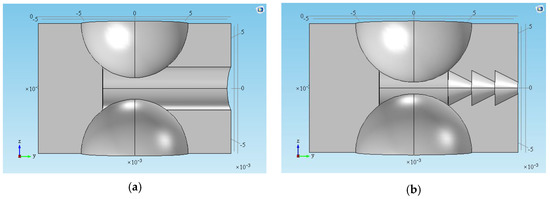
Figure 5.
Structures of the basic SSAC and the optimized SSAC: (a) basic SSAC [6]; (b) optimized SSAC.
Figure 6 is the time-varying curve of the airflow velocity amplitude in the basic SSAC and the optimized one. It shows that the airflow velocity in the basic SSAC contains three peaks, while there are four peaks in the optimized one. Compared with the basic one, the airflow velocity in the optimized SSAC is significantly inceased. The first peak reaches its the maximum velocity (36 m/s) at 1.23 ms, while the maximum velocity in the optimized structure occurs at the second peak at 3.61 ms and it is 318 m/s, which is 8.83 times that of the basic SSAC. The third peak velocity in the optimized SSAC is 282 m/s (7.83 times).
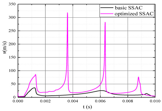
Figure 6.
Airflow velocity of the basic SSAC and optimized SSAC.
Figure 7 illustrates the velocity distribution of airflow at different times in the optimized SSAC and basic SSAC when the arc current is constant (1000 A). Figure 7a shows that the airflow velocity in the basic SSAC is significantly lower than that in the optimized one. In the basic SSAC, the airflow velocity changes slowly, and the peak airflow velocity mainly appears in the gap between the electrodes and near the outlet (see 1.23 ms and 6.03 ms). Figure 7b depicts that the peak airflow velocity of the optimized SSAC mainly distributes between the electrode gap and converging-diverging structure, and the airflow undergoes “two accelerations” due to the two-stage onverging-diverging structure. It shows that the optimized SSAC with multi-stage converging-diverging structure can significantly increase the airflow velocity in the chamber than the basic SSAC. The increasing airflow velocity contributes to the extinction of the arc.
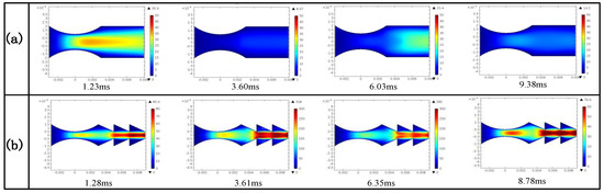
Figure 7.
Distribution of airflow at different times in (a) basic SSAC; (b) optimized SSAC.
4. Experimental Verifications
In order to analyze the arc extinction characteristics of the multi-chamber arc-extinguishing structure, a test platform is set up, as shown in Figure 8. The impulse current generator is charged by 380 V AC power supply through boosting and rectifying. The rated DC charging voltage of the capacitor bank can reach 100 kV, and the maximum short-circuit output current can reach 200 kA. A Rogowski coil current sensor is used to measure the current flowing through the multi-chamber structure. Its maximum permissible peak current is 20 kA. The multi-chamber arc-extinguishing structure is suspended below the conductor. The upper end of multi-chamber arc-extinguishing structure is in electrical contact with the conductor and the lower end is grounded. Once the multi-chamber arc-extinguishing structure is broken down, the oscilloscope gives the trigger signal to the high-speed camera, and arc extinction process in multi-chamber is photographed by the high-speed camera. The high-speed camera used is a FASTCAM SA5 (Photron, San Diego, CA, USA) equipped with a 12-bit monochrome chip (36-bit RGB color) and 20-μm pixels. The frame speed can be adjusted according to the pixels, up to 1,000,000 fps. The camera is controlled by Photron’s Fastcam Viewer (PFV). In this test, the applied current is 2 kA with a standard lighting pulse waveshape of 8/20 μs. We perform experiments applying impulse current of 8/20 form to observe dissipation characteristics of arc and to verify the effectiveness of the optimized SSAC structure.
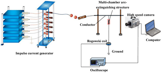
Figure 8.
circuit diagram of impulse current test for the multi-chamber arc-extinguishing structure.
4.1. Case Study
The specific size of the basic structure and optimized structure is shown in Section 3. 3D printing technology is utilized to print the multi-chamber products. 3D printing is a kind of manufacturing technology which takes a 3D digital model file as input, glueable and solidifiable materials as raw materials, and adopts layered printing and layer-by-layer accumulates the material to construct objects. This kind of manufacturing technology does not need traditional tools or molds, and can realize the manufacture of a complex structure which is difficult or impossible to process by traditional technologies, and can effectively simplify the production process and shorten the manufacturing cycle. We use the fused deposition model (FDM) in 3D printing technology and polylactic acid (PLA) as the printing material. Polylactic acid is a biodegradable polymer which causes no pollution to the environment. The electrical properties of PLA [34] have been studied. The volume resistivity, dielectric constant, dielectric loss of PLA are similar to that of crosslinked polyethylene, and the pulse breakdown strength of PLA is 1.3 times that of the crosslinked polyethylene. Therefore, polylactic acid materials were selected to print multi-chamber structure samples. The printing process of 3D printer and the multi-chamber structure printed product are shown in Figure 9.
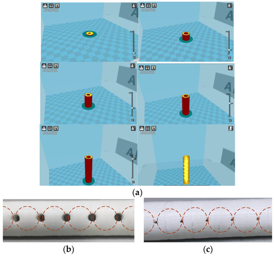
Figure 9.
Multi-chamber arc-extinguishing structure printed by 3D printer: (a) printing sample process of 3D printer; (b) local schematic diagram of basic structure; (c) local schematic diagram of optimized structure.
4.2. Results Discussion
Figure 10 shows the arc extinction process in the basic multi-chamber structure. When the multi-chamber arc-extinguishing structure is broken down at 0 μs, the impulse arc is still in the chamber, and the brightness of the arc is strong, as shown in Figure 10 (1) and (2). After 12 μs, the arc current decreases gradually, and the brightness of the arc increases gradually, then decreases, as shown in Figure 10 (3)–(6), because the change of the arc temperature lags behind the change of the arc current due to the fast-changing impulse current. In this process, the arc plasma sprays from the inside to the outside of the chamber. Because of the strong brightness, the arc sprays in the five chambers are almost integrated, and there is no obvious demarcation until 39.6 μs. Then the arc plasma moves outside the chamber, and the arc brightness and arc diameter decrease gradually, as shown in Figure 10 (7)–(11). After 92.4 μs, almost all the arc plasma moves out of the chamber. Under the action of the drift and diffusion of charged particles, the charged particles in the arc plasma gradually decrease, the arc temperature and brightness gradually decreases. The arc is completely extinguished at 422.4 μs, as shown in Figure 10 (12)–(24).
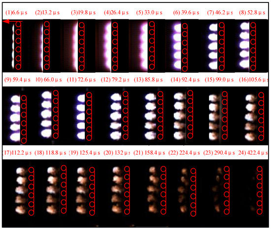
Figure 10.
Arc extinction process in the basic multi-chamber structure.
Figure 11 is the arc extinction process in the optimized multi-chamber structure. The arc jet length in the optimized structure at the same time is obviously longer than that in the basic structure by comparing Figure 10 (1)–(2) and Figure 11 (1)–(2). This indicates that the airflow velocity in the optimized structure is greater than that in the basic structure. The arc plasma is gradually ejected from the inside to the outside of the chamber.
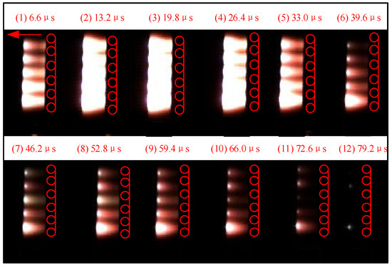
Figure 11.
Arc extinction process in the optimized multi-chamber structure.
The arc brightness and the arc diameter decrease gradually as is shown in Figure 11 (7)–(10). After 72.6 μs, almost all the arc plasma moves outdoors. Under the action of the drift and diffusion of charged particles, the charged particles in the arc plasma gradually decrease, the arc temperature gradually decreases, and the arc is completely extinguished at 79.2 μs, as shown in Figure 11 (11)–(12). Compared with the basic structure, it is found that the dissipation time of arc in the optimized structure is 79.2 μs, which is about 1/5 of the basic structure (422.4 μs). The time of arc dissipation and extinction is significantly shortened, which indicates the structure optimization proposed in this paper is effective. It can improve the arc-extinguishing performance of the multi-chamber arc-extinguishing structure. The multi-chamber arc-extinguishing structure with a multi-stage converging-diverging structure is more conducive for arc-extinguishing.
5. Conclusions
A two-dimensional model of arc plasma in SSAC is built based on the magnetohydrodynamic (MHD) theory with coupled interactions among flow field, temperature field and electromagnetic field. The motion characteristics of the arc in the SSAC are simulated and analyzed. The effects of chamber sizes on the airflow velocity distribution in the arc-extinguishing chamber are compared and analyzed. An SSAC optimization method is proposed and the optimized structure and size are determined. Finally, a multi-chamber arc-extinguishing structure test platform is built. The arc dissipation characteristics in the basic structure and the optimized one are compared. The conclusions are as follows:
- (1)
- Short-gap arcs form a high-speed airflow in a single chamber of the arc-extinguishing structure. The arc root moves rapidly at the junction of the electrode and the insulation wall, and arc plasma sprays to the outlet until the arc is extinguished when the current crosses zero.
- (2)
- The radius (R), electrode-electrode spacing (d1) and opening diameter (d2) of SSAC have significant effects on the airflow distribution in the chamber. Appropriate reduction of R, d1 and d2 can significantly improve the airflow velocity in the chamber. The nozzle length (d3) has little effect on the airflow distribution in the chamber.
- (3)
- When the current is constant, the greater the velocity of generated airflow in SSAC is more conducive to the extinction of the arc. A multi-stage converging-diverging structure on the SSAC nozzle is proposed and designed, the airflow velocity in the chamber can be accelerated in the converging-diverging structure, which effectively improves the airflow velocity in the arc-extinguishing chamber. The airflow velocity in the optimized structure can be increased to about 8 times that of the the basic structure.
- (4)
- Experiments show that the arc dissipation time in the optimized structure is 79.2 μs, which is significantly less than that in the basic structure (422.4 μs). This shows that the multi-stage converging-diverging structure is beneficial to the dissipation and extinction of arcs, and proves the feasibility of the structure optimization. The multi-stage converging-diverging structure proposed in this paper can be used to optimize the structure of multi-chamber arc-extinguishing structures and improve thei arc-extinguishing performance.
Author Contributions
The authors gratefully acknowledge the contributions as following: W.S. conceived and designed the experiments; W.J., T.Y., M.Y. and P.S. performed the experiments; W.J. analyzed the data and wrote the paper.
Funding
This work was supported financially by the the National Natural Science Foundation of China (51837002).
Conflicts of Interest
The authors declare no conflict of interest.
References
- He, J.L.; Gu, S.Q.; Chen, S.M.; Zeng, R.; Chen, W. Discussion on measures against lightning breakage of covered conductors on distribution lines. IEEE Trans. Power Deliv. 2008, 23, 693–702. [Google Scholar]
- Chen, W.; Sun, Z.; Li, G.; Cui, J.L.; Feng, J.L.; Tang, S.Y.; Li, M.G.; Yu, J.L.; Liao, F.W.; Bao, J.Q. Development of parallel gap lightning protection device for 110 kV and 220 kV overhead lines. Power Syst. Technol. 2006, 30, 70–75. [Google Scholar]
- Lee, R.E.; Fritz, D.E.; Stiller, P.H.; Shankle, D.F. Prevention of Covered Conductor Burndown on Distribution Circuits-Arcing Protection Devices. IEEE Power Eng. Rev. 2010, 2, 18–19. [Google Scholar]
- Chino, T.; Iwata, M.; Imoto, S.; Nakayama, M.; Sakamoto, H.; Matsushita, R. Development of arcing horn device for interrupting ground-fault current of 77 kV overhead lines. IEEE Trans. Power Deliv. 2005, 20, 2570–2575. [Google Scholar] [CrossRef]
- Hashimoto, Y.; Fukui, H.; Yano, T.; Tsukazaki, M.; Sakakiwara, M. Development of Current Limiting Arcing Horn (MOV type arrester with external gap) for 22 kV power distribution line. In Proceedings of the IEEE Asia-Pacific International Conference on Lightning, Chengdu, China, 1–4 November 2011; pp. 36–39. [Google Scholar]
- Podporkin, G.V.; Enkin, E.Y.; Kalakutsky, E.S.; Pilshikov, V.E.; Sivaev, A.D. Overhead lines lightning protection by multi-chamber arresters and insulator-arresters. IEEE Trans. Power Deliv. 2011, 26, 214–221. [Google Scholar] [CrossRef]
- Podporkin, G.V.; Enkin, E.Y.; Pilshikov, V.E. The development of multichamber arresters. Russ. Electr. Eng. 2013, 84, 1–5. [Google Scholar] [CrossRef]
- Guo, T.; Zhou, W.; Su, Z.; Li, H.; Yu, J. A Multigap Structure for Power Frequency Arc Quenching in 10-kV Systems. IEEE Trans. Plasma Sci. 2016, 44, 2622–2631. [Google Scholar] [CrossRef]
- Swierczynski, B.; Gonzalea, J.J.; Teulet, P.; Freton, P.; Gleizes, A. Advances in low voltage circuit breaker modelling. J. Phys. D Appl. Phys. 2004, 37, 595–609. [Google Scholar] [CrossRef]
- Wang, Z.; He, J.; Zou, J. Power Switch Technology; Huazhong University of Science and Technology Press: Wuhan, China, 2003; pp. 179–193. ISBN 9787560930251. [Google Scholar]
- Giere, S.; Karner, P.H.C. Dielectric strength of double and single-break vacuum interrupters. IEEE Trans. Dielectr. Electr. Insul. 2001, 8, 43–47. [Google Scholar] [CrossRef]
- Tseng, K.J.; Wang, Y. Development of a Dynamic Model of Electric Arc for Power Electronics Simulations. IEEE Conf. Ind. Appl. 1996, 4, 2173–2180. [Google Scholar]
- Mokhtari, H.; Hejri, M. A New Three Phase Time-domain Model for Electric Arc Furnaces Using MATLAB. IEEE Conf. Transm. Distrib. 2002, 3, 2078–2083. [Google Scholar]
- Vander sluis, L.; Rutgers, W.R.; Koreman, C.G.A. A Physical Arc Model for the Simulation of Current Zero Behavior of High-voltage Circuit Breakers. IEEE Trans. Power Deliv. 1992, 7, 1016–1022. [Google Scholar] [CrossRef]
- Habedank, U. On the Mathematical Description of Arc Behavior in the Vicinity of Current Zero. Etz Arch. 1988, 10, 339–343. [Google Scholar]
- Schavemaker, P.H.; Vander Sluis, L. An Improved Mayr-type Arc Model Based on Current-zero Measurements. IEEE Trans. Power Deliv. 2000, 15, 580–584. [Google Scholar] [CrossRef]
- Schavemaker, P.H. Arc Model Blockset. In Proceedings of the Second IASTED International Conference Power and Energy Systems (EuroPES), Crete, Greece, 25–28 June 2002. [Google Scholar]
- Smeets, R.P.P.; Kertesz, V. Evaluation of High-voltage Circuit Breaker Performance Witha Validated Arc Model. IEEE Proc. Gener. Transm. Distrib. 2000, 147, 121–125. [Google Scholar] [CrossRef]
- Lowke, J.J.; Kovitya, P.; Schmidt, H.P. Theory of free-burning arc columns including the influence of the cathode. J. Phys. D Appl. Phys. 1992, 25, 1600. [Google Scholar] [CrossRef]
- Horinouchi, K.; Nakayama, Y.; Hidaka, M.; Yonezawa, T.; Sasao, H. A method of simulating magnetically driven arcs. IEEE Trans. Power Deliv. 1997, 12, 213–218. [Google Scholar] [CrossRef]
- Zhainakow, A. Three-dimensional Mathematical Model for the Calculation of Electric-arc Plasma Flows. High Temp. 2002, 40, 9–14. [Google Scholar] [CrossRef]
- Wu, Y.; Rong, M.; Li, X.; Murphy, A.B.; Wang, X.; Yang, F.; Sun, Z. Numerical Analysis of the Effect of the Chamber Width and Outlet Area on the Motion of an Air Arc Plasma. IEEE Trans. Plasmaence 2008, 36, 2831–2837. [Google Scholar]
- Chadebec, O.; Meunier, G.; Mazauric, V.G.; Le Floch, Y.; Labie, P. Eddy-current effects in circuit breakers during arc displacement phase. IEEE Trans. Magn. 2008, 40, 1358–1361. [Google Scholar] [CrossRef]
- Wu, Y.; Rong, M.; Sun, Z.; Wang, X.; Yang, F.; Li, X. Numerical analysis of arc plasma behaviour during contact opening process in low-voltage switching device. J. Phys. D Appl. Phys. 2007, 40, 795–802. [Google Scholar] [CrossRef]
- Freton, P.; Gonzalez, J.J.; Ranarijaona, Z.; Mougenot, J. Energy equation formulations for two-temperature modelling of ‘thermal’ plasmas. J. Phys. D Appl. Phys. 2012, 45, 465206. [Google Scholar] [CrossRef]
- Wu, Y.; Li, M.; Rong, M.; Yang, F.; Murphy, A.B.; Wu, Y.; Yuan, D. Experimental and theoretical study of internal fault arc in a closed container. J. Phys. D Appl. Phys. 2014, 47, 505204. [Google Scholar] [CrossRef]
- Zhang, J.L.; Yan, J.D.; Murphy, A.B.; Hall, W.; Fang, M.T. Computational investigation of arc behavior in an auto-expansion circuit breaker contaminated by ablated nozzle vapor. IEEE Trans. Plasma Sci. 2002, 30, 706–719. [Google Scholar] [CrossRef]
- Zhang, J.L.; Yan, J.D.; Fang, M.T.C. Investigation of the effects of pressure ratios on arc behavior in a supersonic nozzle. IEEE Trans. Plasma Sci. 2000, 28, 1725–1734. [Google Scholar] [CrossRef]
- Yos, J. Revised transport properties for high temperature air and its components. AVCO Space Syst. Div. Tech. Release 1967, 16, 10014936914. [Google Scholar]
- Lei, Z.S.; Garimella, S.V.; Chan, S.H. Gas dynamics and electromagnetic processes in high-current arc plasmas. Part II. Effects of external magnetic fields and gassing materials. J. Appl. Phys. 1999, 85, 2547–2555. [Google Scholar]
- Freton, P.; Gonzalez, J.J.; Gleizes, A. Comparison between a two- and a three-dimensional arc plasma configuration. J. Phys. D Appl. Phys. 2000, 33, 2442–2452. [Google Scholar] [CrossRef]
- Lowke, J.J.; Morrow, R.; Haidar, J. A simplified unified theory of arcs and their electrodes. J. Phys. D Appl. Phys. 1997, 7, 2033–2042. [Google Scholar] [CrossRef]
- Liu, Y.J.; Chang, G.W.; Huang, H.M. Mayr’s equation-based model for Pantograph Arc of high-speed railway traction system. IEEE Trans. Power Deliv. 2010, 25, 2025–2027. [Google Scholar] [CrossRef]
- Nakagawa, T.; Nakiri, T.; Hosoya, R.; Tajitsu, Y. Electrical properties of biodegradable polylactic acid film. IEEE Trans. Ind. Appl. 2003, 40, 1020–1024. [Google Scholar] [CrossRef]
© 2018 by the authors. Licensee MDPI, Basel, Switzerland. This article is an open access article distributed under the terms and conditions of the Creative Commons Attribution (CC BY) license (http://creativecommons.org/licenses/by/4.0/).