Effect of Saturation on Field Oriented Control of the New Designed Reluctance Synchronous Motor

Department of Power Electrical Systems, Faculty of Electrical Engineering, University of Zilina, 010 26 Zilina, Slovakia
*
Author to whom correspondence should be addressed.
Energies 2018, 11(11), 3223; https://doi.org/10.3390/en11113223
Submission received: 15 October 2018
/
Revised: 12 November 2018
/
Accepted: 19 November 2018
/
Published: 21 November 2018
(This article belongs to the Special Issue Selected Papers from EEEIC 2018—18th International Conference on Environment and Electrical Engineering)
Abstract
:In this paper the effect of saturation on torque production of a reluctance synchronous motor (RSM), which was originally built as an induction motor (IM), is investigated. The rotor was replaced with new one, designed as synchronous reluctance cageless rotor with barriers, the shape and number of which were optimized to maximize the reluctance ratio. The torque measurement was done while the RSM was fed by frequency converter controlled by a microcontroller with closed loop field oriented control strategy to find out how saturation effects the developed torque at various values of the currents and speeds. It is shown how the load angle at which the maximum torque was achieved is changed. It was found out that the load angle was shifted to higher values depending on the speed of operation.
1. Introduction
In many industrial or other applications where electrical machines are used, strong emphasis is placed on lower energy consumption. This can be achieved by new materials, new design topologies, optimization or energy saving control strategies, if the electrical machine is used as a drive with converter [1,2]. The most common electrical machines used in the industry are squirrel cage induction motors (IM) because of their low costs, robustness and maintenance. Nowadays, in many applications, the controlled electric drives are required to obtain various speed and better dynamic parameters. In this case, the accurate control systems for IM are more complicated, because of rotor resistance dependence on the temperature.
With advent of affordable silicon power semiconductors and powerful computing chips arises the opportunity to use variable speed control in industrial applications. Induction machine (IM) is the most common drive among the industry applications on many power levels. It is often used in direct-on-line (DOL) mode of operation, what decreases the efficiency of electric drive. The use of variable speed control for IM is common but brings new challenges in terms of efficiency and reliability of control process.
The RSM with comparable output parameters with IM seems to provide good compensation [2]. During design process, the main idea is to maximize the ratio between synchronous inductances in direct axis Ld and in quadrature axis Lq. This feature is very important from the point of view of developed reluctance electromagnetic torque [1]. On the other hand, the high inductance ratio Ld/Lq leads to possible instability of RSM which works with DOL. In such a case, the RSM must work from frequency converter with scalar or vector control algorithms. This depends on the application area, and how precise control is needed [2]. The main disadvantage of such a motor is a lower power factor and higher torque ripple. The rotor structure of RSM can be determined from quite simple to very complex and this construction structure can have a very important influence on final RSM parameters.
In the IM, some faults can occur, which are caused by squirrel bars failures [3]. Reluctance synchronous motor (RSM) can become a competitor to an already widely used IM. RSM has some advantages in comparison to IM: No winding and joule losses on the rotor of RSM, smaller moment of inertia, lower manufacturing costs, smaller size, and operating in synchronism with a rotating magnetic field.
Having no winding on the rotor means there are no joule losses which are responsible for heating. The rotor of RSM is made of iron laminations with barriers, usually made of air. Such a design makes RMS easy to produce and less source-dependable, since there is no need for aluminum or copper to be embedded in the rotor. It is also easier to recycle or repair such a machine. The stator is the same or with little variations as used for IM, which also brings the cost of production down.
Smaller moment of inertia is caused by the air in the barriers of rotor, which is lighter than the iron or copper or aluminum. Synchronous operation means control strategies for synchronous drives can be used. These strategies are considered less complex and more reliable during variable speed operation.
Scientific research of RSM is oriented towards improving some performances of IM [4,5] with an ability to withstand higher temperature [6] or to produce a higher torque in the same rotor volume [7,8,9,10] which means the torque per unit (volume or mass) is higher than in the case of IM. Other research can be focused on RSM design optimization by means of various methods such as by using multi-objective optimization with an altered bee colony optimization and Taguchi method [11]. Some others are focused on improvement qualitative parameters such as the torque ripple decreasing and output torque increasing [12]. The authors in Reference [13] evaluate the electromagnetic and thermal performance of several traction motors for electric vehicles (EVs) when RSM is used as traction drive. In Reference [12], authors described the rotor design of RSMs with a large effect on their efficiency, torque density and torque ripple. In order to achieve a good compromise between these three goals, optimized rotor geometry is necessary.
Disadvantages exist as well. RMS can operate in DOL mode only when damper or cage is present in rotor of the machine, which would allow machine to start itself up. Damper or cage makes the machine heavier and more expensive. Thus, almost all RSM are cageless and can be operated only with frequency converter or starting device.
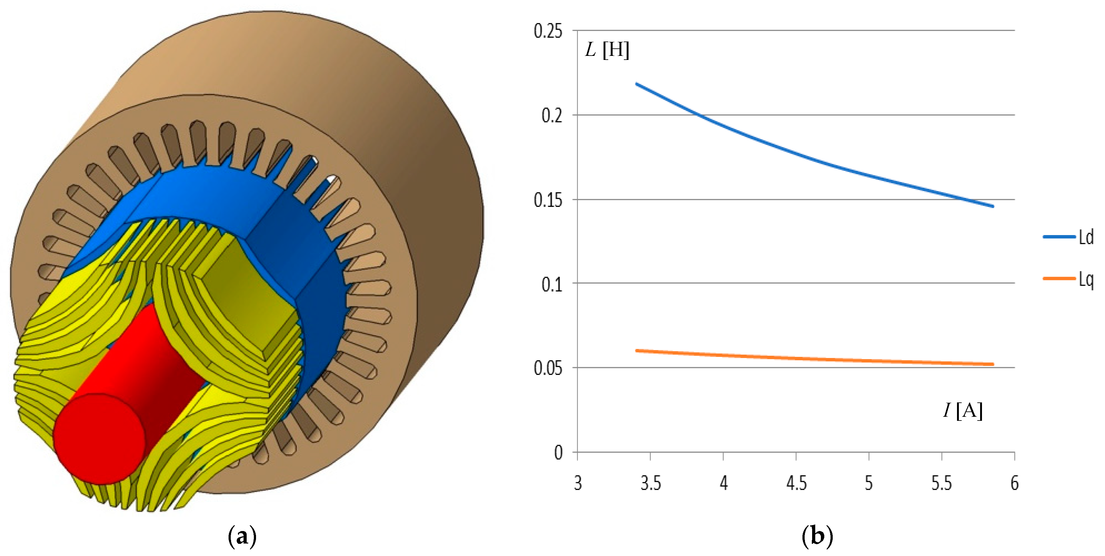
In this paper the effect of saturation on torque production of RSM, which was originally built as an induction motor (IM), is investigated. The rotor was replaced with new one, designed as a synchronous reluctance cageless rotor with barriers, the shape and number of which were optimized to maximize the reluctance ratio [14], (Figure 1a). The torque measurement was done while the RSM was fed by frequency converter controlled by a microcontroller with closed loop field oriented control strategy to find out how saturation affects the developed torque at various values of the currents. It is shown how the load angle at which the maximum torque was achieved is changed. This load angle was shifted to higher values depending on the speed of operation.
The rated parameters with regards to original stator are as follows: 1.5 kW, ∆/Y 230/400 V, 3.4 A, 1500 rpm, 2p = 4. Measured characteristics are the torque output and power factor (PF) when load angle is variable.
The main aim of this paper is to examine the importance and influence of saturation on the performance of the RSM. It is known that the total developed torque of the RSM depends on the ratio of synchronous reactances Xd, Xq in d and q axis, and their difference as follows:
These reluctances depend on the saturation effect. With higher currents and excitation of the magnetic circuit in motor, the reactances decrease, which results in a lower ratio and lower torque, see Equation (1) and Figure 1b. The optimization of rotor was applied to find out an optimal number and shape of the barriers to maximize the reluctance ratio [14]. However, the saturation effect may still have a negative impact on the torque production.
2. Equivalent Circuit Parameters Identification
To be able to investigate an effect of saturation to equivalent circuit parameters and torque development, it is necessary to determine the parameters by calculation and then to verify them by measurement. Very important parameters from the point of view of control system set up are the equivalent circuit parameters such as stator resistance, stator leakage inductance, magnetizing inductances in the d and q axis and rotor parameters, if the rotor cage is used. In accordance with the authors’ experiences, the cageless rotor has also some value of parameters due to electrical conductivity of rotor sheets and their welding. In such a case, the equivalent circuit must be extended by rotor parameters as leakage inductance LD,Q and resistance RD,Q in d and q axis are referred to the stator. These parameters were measured. All equivalent circuit parameters were investigated by several methods: By Finite Element Method (FEM), by calculation on the base of theory of the design of electrical machine, and third, by measurements.
2.1. FEM Analysis of the RSM Parameters
The FEM is a numerical method which enables us to investigate parameters and performances of the electrical machines on the base of the electromagnetic field distribution in the machine cross section area (2D version). All geometrical dimensions, properties of the materials and many data of the windings must be known. Because the FEM Magnetics 2D version doesn′t include end windings and leakage flux, it is therefore necessary to add these values gained by additional calculation.
The waveform of the airgap flux density around the periphery, induced voltage, magnetic flux linkage, inductances, developed electromagnetic torque and torque ripple are possible to investigate by means of FEM. The magnetic flux distribution for rated current in d and q axis in the new optimized cageless barriers rotor was reported in Reference [1].
2.2. Synchronous Inductances Calculations
Synchronous inductance consists of two components: Magnetizing Lμ and stator leakage it’s OK.inductance Lσs. The leakage inductance is taken from analytical approach and its value is stated to Lσs = 23.7 mH. In Figure 1b, synchronous inductances in the d and q axis are seen versus phase current obtained by means of FEM, including leakage inductance. It is seen how the inductances are influenced by higher current, which means by higher saturation.
2.3. Electromagnetic Torque Calculation
According to Equation (1) the developed electromagnetic torque of the RSM is given by the synchronous reactances ratio and their difference in d and q axis and quadrant of the supplied phase voltage. In the FEM is possible to simulate a waveform of the electromagnetic torque versus load angle ϑL for constant rms phase current. The stator winding is fed by three phase current at certain instances, e.g., in A phase there is a positive magnitude of the rated current and in B and C, there is the negative half of the magnitude. In such cases these currents create an instantaneous static electromagnetic torque. Therefore the rotor must be gradually moved up along 360° electrical. Under used FEM software, the electromagnetic torque can be calculated by several methods: from Maxwell stress tensor, from coenergy or from Lorenz′ force. In this analysis, the Maxwell stress tensor is used. On the figure of Section 3.1 there is an orange line of the torque got by means of the FEM analysis for rated current versus load angle. It is analyzed for static condition.
2.4. Measurements of the RSM Parameters
The synchronous inductances were measured by means of DC decay test described in many papers or standards. It is simple and enough accurate method. The comparison of the reached results from FEM and such measurements is shown in Table 1.
As is seen from Table 1, the calculated and measured values are in very good coincidence and the differences are lower than 10%.
The second comparison is shown in Table 2, where the induction motor and optimized cageless barriers RSM rotor parameters are shown for the same stator and the same phase current 3.4 A.
From this comparison, it can see that the output torque of new designed RSM rotor is comparable with the induction motor. In the future, the losses, power factor and efficiency will be analyzed for various control systems as scalar or vector algorithms.
3. Torque Measurement at the Field Oriented Control
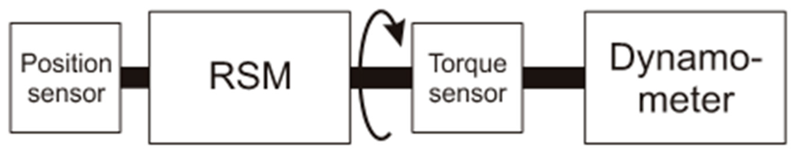
Torque measurement was done while the motor was fed by frequency converter controlled by microcontroller with the closed loop field oriented control (FOC) strategy [15]. Motor shaft was coupled with dynamometer so the torque produced by motor was possible to measure, see Figure 2. During the measurement, the rms value of phase current was held constant as well as the speed of rotation. Load angle was the variable during measurement. It was held between 30° and 80° for the purposes of measurement with the microcontroller and frequency converter. Torque produced by motor was measured with dynamometer operated in closed speed loop and motor operated in a closed current loop.
Measured electromagnetic torque of the motor versus the load angle is in the Figure 3. There are six curves in the plot, each for different level of phase current, while the value of current was held constant during each measurement. The speed of rotation for measurements in Figure 3 was 500 rpm. It is three times less than rated speed of this motor.
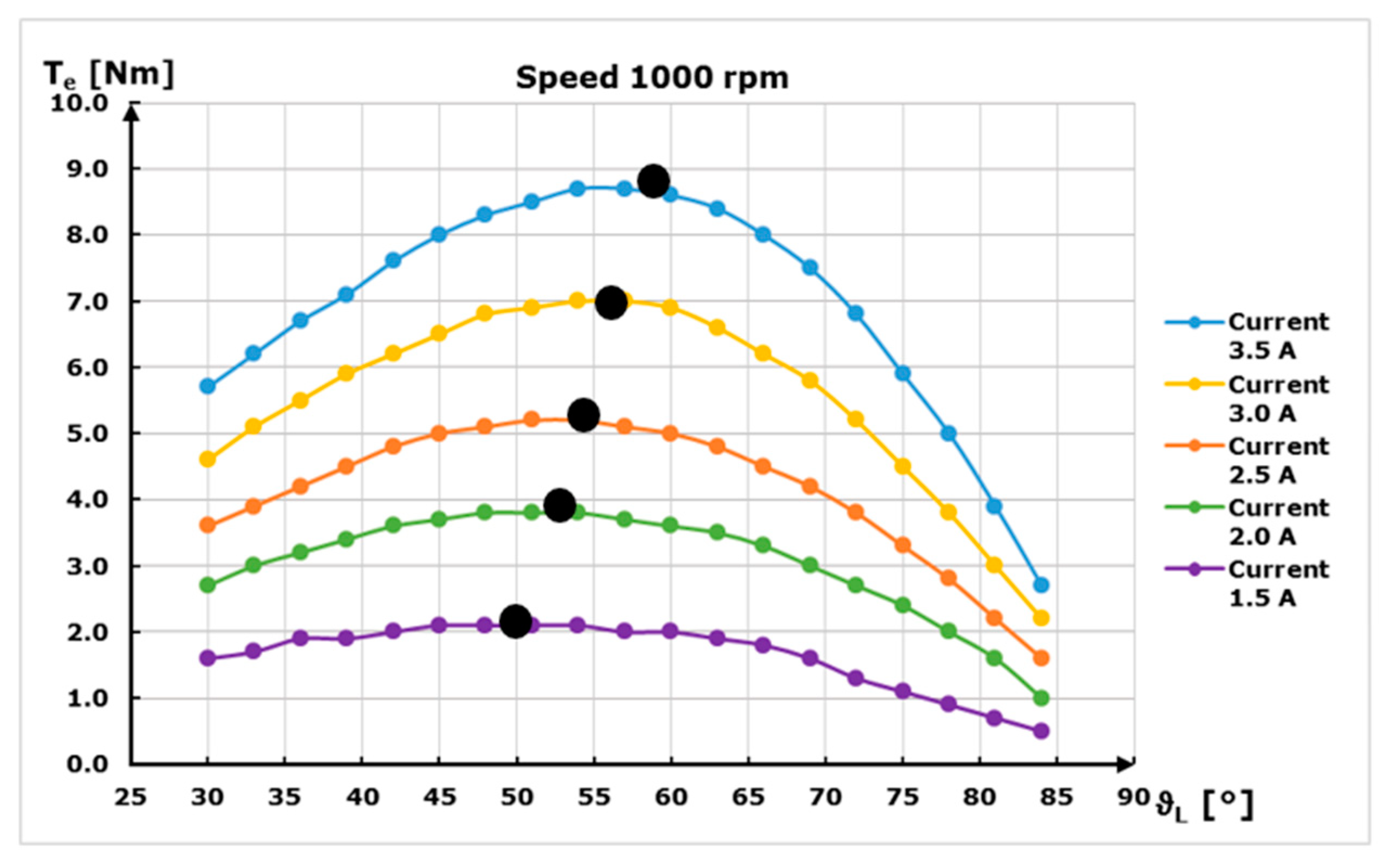
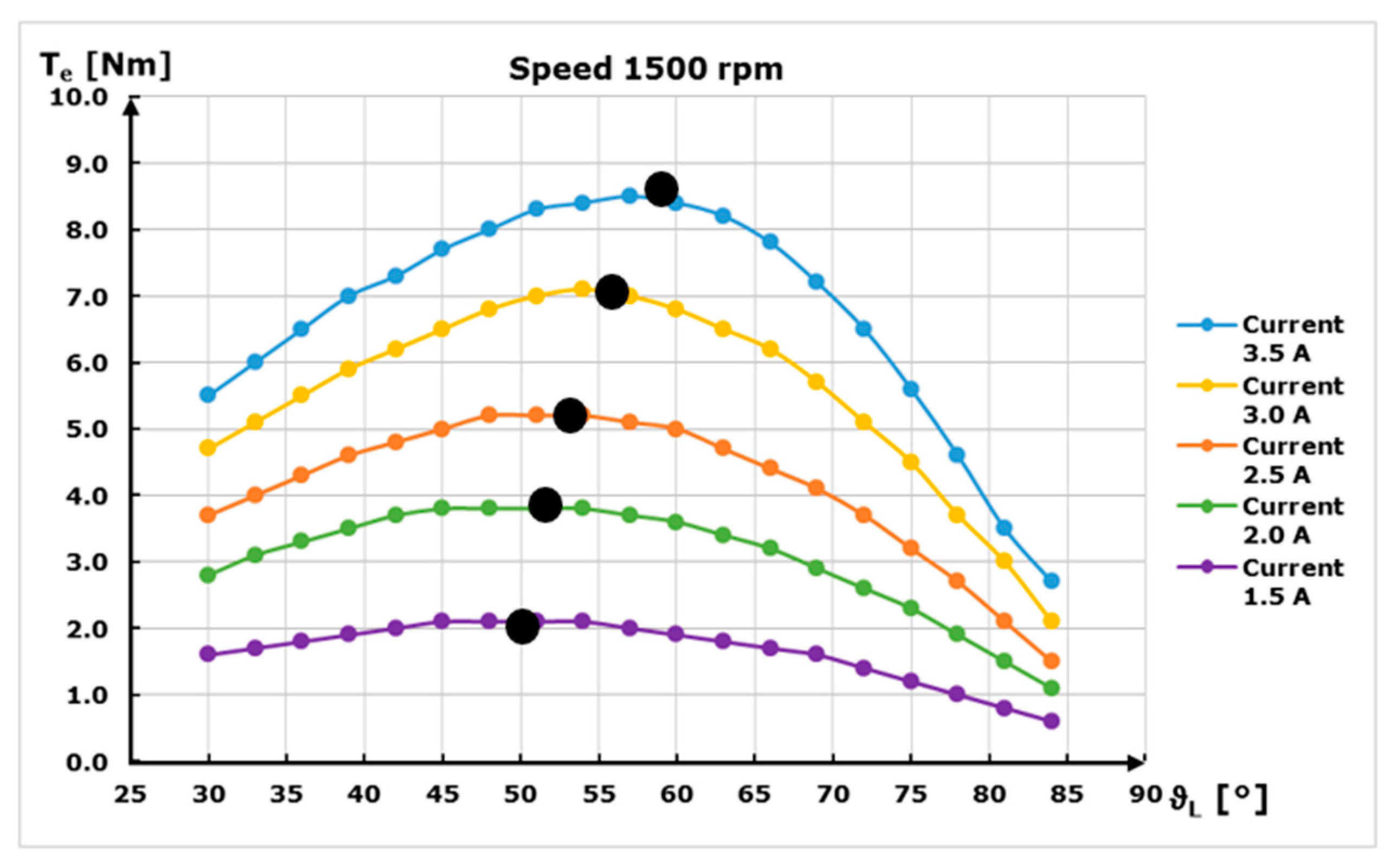
Similar measurements are in Figure 4, but at a doubled speed, 1000 rpm. The highest attainable phase current value was lower than the rated current. In pictures (see Figure 3, Figure 4 and Figure 5) there are black dots, marking the position of maximal torque produced with the given current during the measurement. These dots show the drift of maximal torque produced by motor towards higher load angle, when the phase current rises. This can affect performance and efficiency of electric drive, if it is not considered in the control algorithm. The shift is related to saturation in magnetic circuit of motor and its influence on the parameters, such as synchronous inductances.
In Figure 5, the torque versus load angle at 1500 rpm can be seen, which is rated as the speed for various phase currents. As can be seen from Figure 3, Figure 4 and Figure 5, the maximal torques are equivalent for the same phase current and different speed. For instance, the maximal torque occurs for rated phase current 3.5 A at load angle 57° for all three speeds 500, 1000 and 1500 rpm.
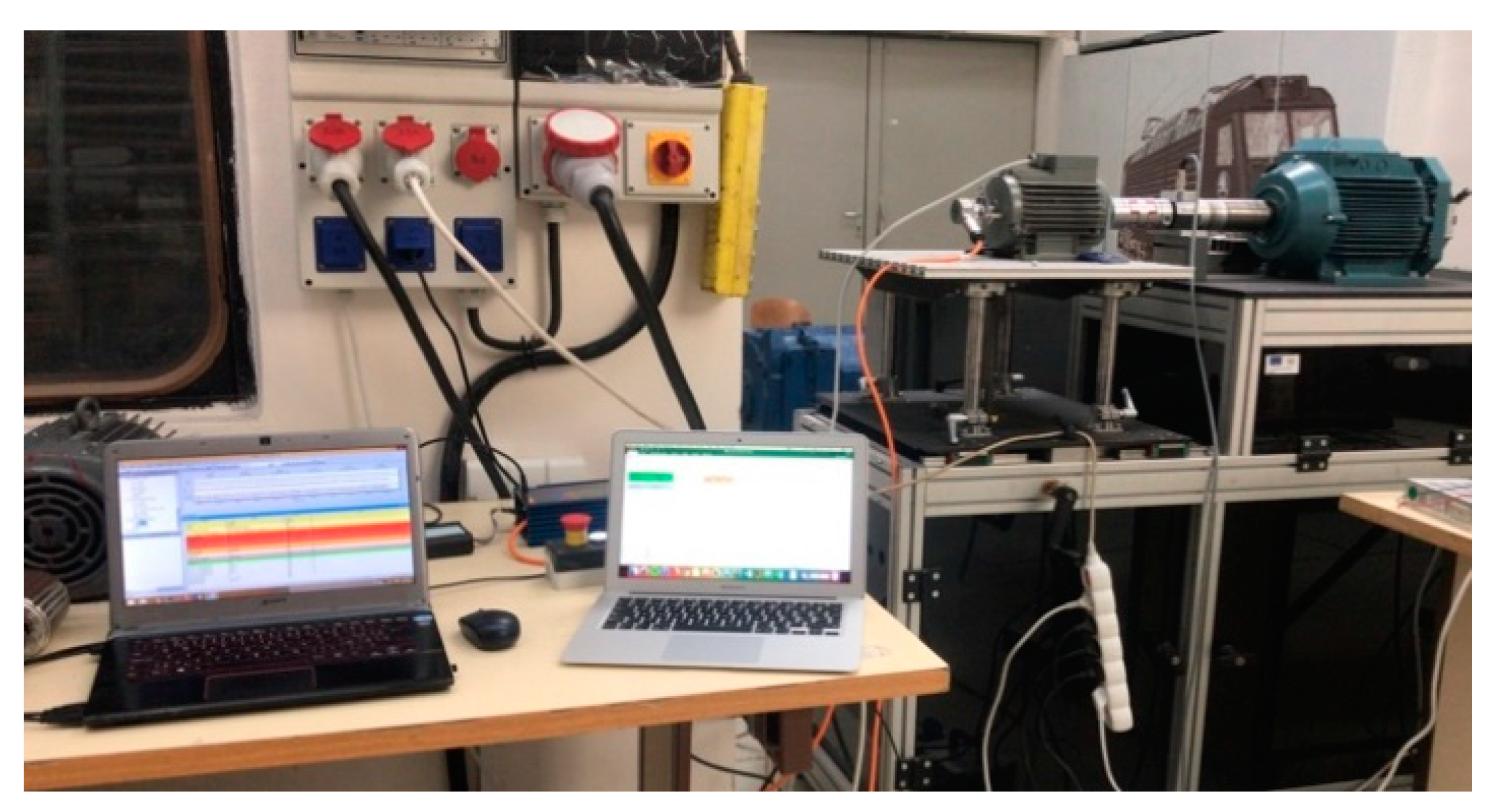
In Figure 6 there is a photo of an experimental setup of dynamometer and RSM. In Figure 7, there is a block diagram of the control in a current loop with a possibility to enter the load angle.
3.1. FEM Analysis and Its Comparison with Measurement
The measured characteristic of produced static torque for rated current was compared with the results from FEM analysis. This analysis uses computer power for investigation of electromagnetic field distribution in electric machine. 2D mode with cross section of the investigated RSM was used for analysis of torque transferred over airgap of the machine. The closer approach of the FEM analysis of this motor can be found in Reference [1].
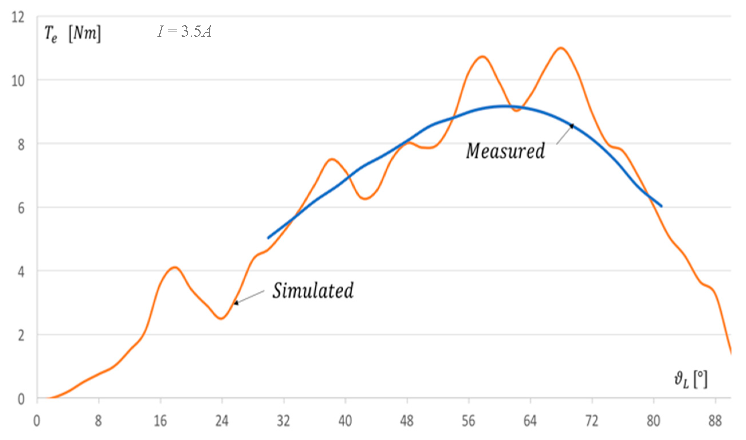
The comparison of measured torque and simulated torque is in Figure 8. The orange curve depicts the simulated torque production of the motor in static condition. This is due to the nature of the FEM analysis used in Reference [1], where the stator was fed with current equivalent to the desired AC current and the rotor was positioned in an angle matching the load angle, but in a non-rotating state. Thus, there was no damping caused by rotation and moment of inertia. The blue curve shows the measured torque at rated current. Blue and orange curves are matching, although ripples are present on orange curve representing simulation. For rated current the maximal measured torque was 9.2 Nm, which matches with the simulation for load angle of 63° electrical.
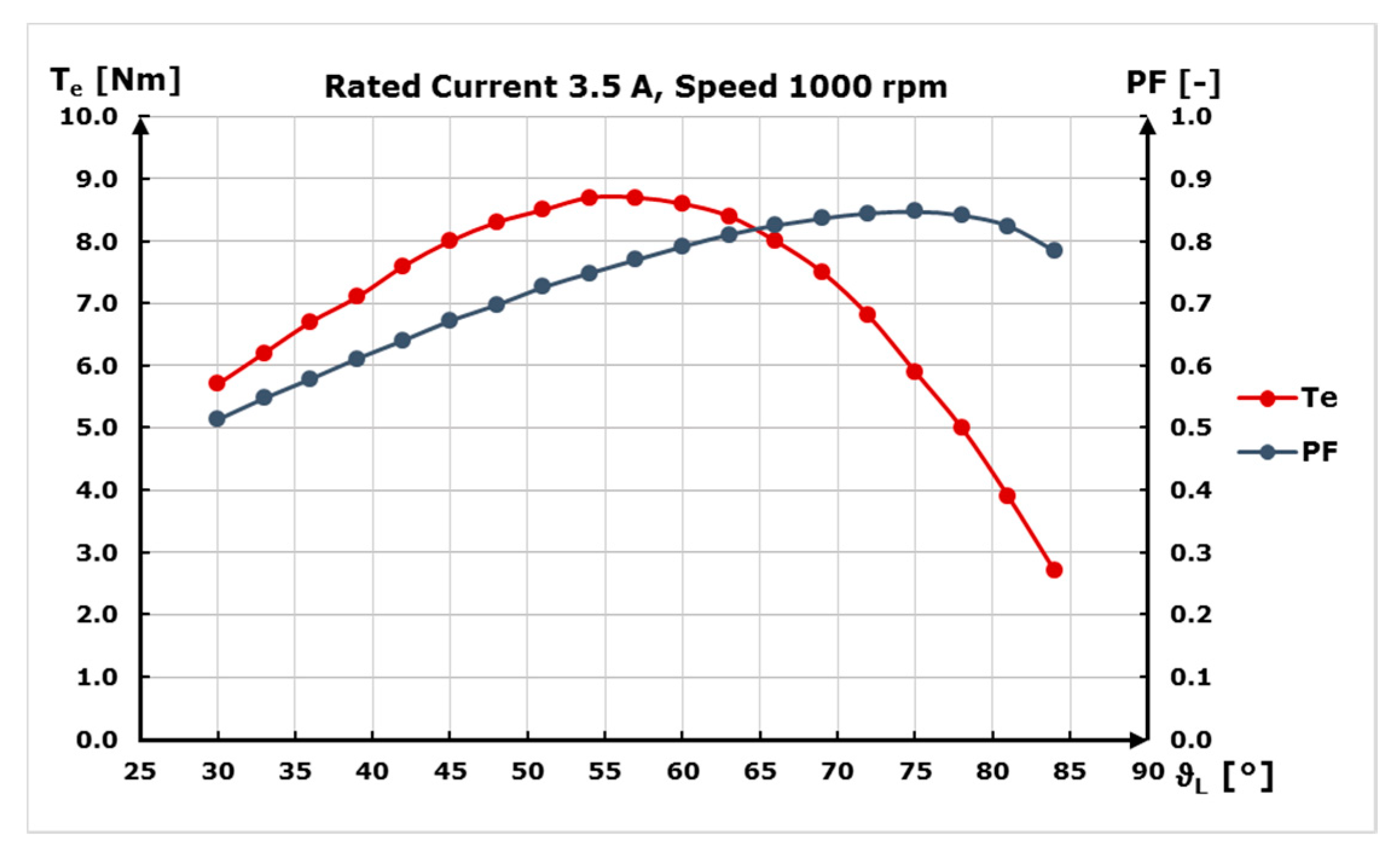
3.2. Power Factor Measurement
RSM often have a lower power factor than similar electric motors with a comparable power and size [16]. This is due to the fact that RSM has no internal source of excitation and therefore the machine must get the magnetic energy needed for excitation from the converter (or another source) itself. That usually leads to a bigger and bulkier frequency converter. However, there exists RSM with permanent magnets embedded and precisely located in the rotor to boost the power factor, so the converter needed for operation is smaller.
During the torque measurement, the power factor was also measured, to see the effect of control and performance of the motor and converter.
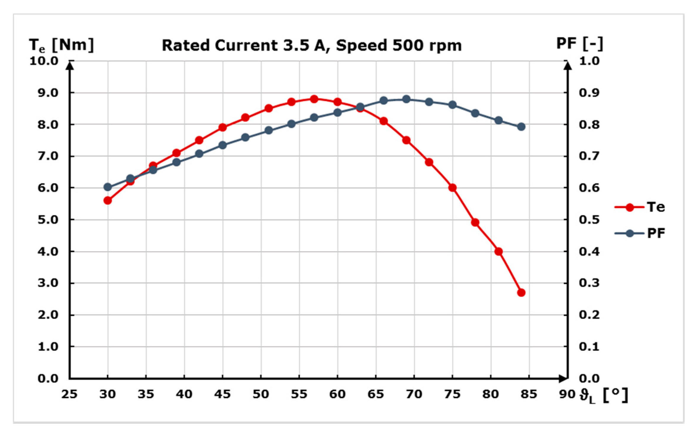
The results can be seen in Figure 9, Figure 10 and Figure 11 where the torque and power factor are displayed as functions of load angle for various speed 500, 1000 and 1500 rpm. The power factor was increasing with the load angle and reached a value of 0.871 at maximal torque (9.2 Nm). This value is higher than expected and the reason for that may be the length of the airgap. The airgap in this motor is 0.18 mm, because this rotor was fabricated as a model and the aim was to achieve as small an air gap as possible to keep a high PF even with no excitation source in the motor.
4. Conclusions
The effect of saturation on FOC of the new designed RSM was investigated by means of measurement and FEM simulation. Measurements of RSM analyzed in this paper show the effect of saturation on the developed electromagnetic torque. The investigated torque as a function of load angle shows the drift towards the higher load angles for increasing phase current (measured up to rated value). The measurements at rated speed are highly recommended, with a power-sufficient frequency converter. Another set of measurements for an efficiency map should be considered in future investigation. It is also recommended to implement an algorithm in control strategy for setting the best load angle to achieve highest possible torque within any load condition of drive. It means setting the correct load angle in closed loop FOC for the corresponding phase current.
Author Contributions
The parts of all authors can be stated as follows. P.R. conceptualization and measurement methodology; V.H. design and optimization of new designed RSM rotor, conceptualization and supervision; P.L. measurements and results validation; P.M control method implementation; F.H. simulation, measurement and results evaluation.
Funding
This research received no external funding.
Acknowledgments
This work was supported by Slovak Scientific Grant Agency VEGA No. 1/0957/16. This work was supported by project ITMS: 26210120021, co-funded from EU sources and European Regional Development Fund. The authors also wish to thank for the support to the R&D operational program Centre of excellence of power electronics systems and materials for their components, ITMS 2622012046, funded by European Community.
Conflicts of Interest
The authors declare no conflict of interest.
References
- Rafajdus, P.; Hrabovcova, V.; Lehocky, P.; Makys, P.; Sebest, M. Analysis and Measurements of New Designed Reluctance Synchronous Rotor. In Proceedings of the 18th IEEE International Conference on Environment and Electrical Engineering, Palermo, Italy, 12–15 June 2018. [Google Scholar]
- Pyrhonen, J.; Jokinen, T.; Hrabovcová, V. Design of the Rotating Electrical Machines, 2nd ed.; WILEY: West Sussex, UK, 2014; ISBN 978-1-118-58157-5. [Google Scholar]
- Bernat, P.; Hytka, Z.; Kacor, P. Indication of failures of rotor bar on induction machine with squirrel cage rotor in its external electromagnetic field. In Proceedings of the 2015 16th International Scientific Conference on Electric Power Engineering (EPE), Kouty nad Desnou, Czech Republic, 20–22 May 2015. [Google Scholar]
- Lipo, T.A. Synchronous Reluctance Drives. In Proceedings of the Tutorial Presented at IEEE IAS Annual Meeting, Denver, CO, USA, 2–5 October 1994. [Google Scholar]
- Mohanarajah, T.; Rizk, J.; Nagrial, M.; Hellany, A. Design of Synchronous Reluctance Motors with Improved Power Factor. In Proceedings of the 11th IEEE International Conference on Compatibility, Power Electronics and Power Engineering, Cadiz, Spain, 4–6 April 2017. [Google Scholar]
- Ki-Chan, K.; Joon Seon, A.; Sung Hong, W.; Jung-Pyo, H.; Lee, J. A Study on the optimal design of SynRM for the high torque and power factor. IEEE Trans. Magn. 2007, 43, 2543–2545. [Google Scholar]
- Lavrinovicha, L.; Dirba, J. Comparison of Permanent Magnet Synchronous Motor and Synchronous Reluctance Motor Based on Their Torque Per Unit Volume. In Proceedings of the 2014 Electric Power Quality ans Supply Reliability Conference, Rakvere, Estonia, 11–13 June 2014. [Google Scholar]
- Pellegrino, G.; Cupertino, F.; Gerada, C. Automatic design of synchronous reluctance motors focusing on barrier shape optimization. IEEE Trans. Ind. Appl. 2015, 51, 1465–1474. [Google Scholar] [CrossRef]
- Chai, W.; Zhao, W.; Kwon, B. Optimal design of wound field synchronous reluctance machines to improve torque by increasing the saliency ratio. IEEE Trans Magn. 2017, 53. [Google Scholar] [CrossRef]
- López, C.; Michalski, T.; Espinosa, A.; Romeral, L. Rotor of Synchronous Reluctance Motor Optimization by Means Reluctance Network and Genetic Algorithm. In Proceedings of the 2016 XXII International Conference on Electrical Machines (ICEM), Lausanne, Switzerland, 4–7 September 2016. [Google Scholar]
- Lin, C.-H.; Hwang, C.-C. High performances design of a six-phase synchronous reluctance motor using multi-objective optimization with altered bee colony optimization and Taguchi method. Energies 2018, 11, 2716. [Google Scholar] [CrossRef]
- Ibrahim, M.N.F.; Sergeant, P.; Rashad, E. Simple design approach for low torque ripple and high output torque synchronous reluctance motors. Energies 2016, 9, 942. [Google Scholar] [CrossRef]
- Huynh, T.A.; Hsieh, M.-F. Performance analysis of permanent magnet motors for electric vehicles (EV) traction considering driving cycles. Energies 2018, 11, 1385. [Google Scholar] [CrossRef]
- Hrabovcová, V.; Makyš, P.; Rafajdus, P.; Šebest, M. Improved barriers rotor of the reluctance synchronous motor. Electr. Eng. 2017, 99, 1325–1335. [Google Scholar] [CrossRef]
- Freescale High-Voltage Motor Control Platform User’s Guide. Available online: https://www.nxp.com/docs/en/user-guide/HVPMC3PHUG.pdf (accessed on 17 January 2018).
- Boldea, I. Reluctance Synchronous Machines and Drives; Clarendon Press: Oxford, UK, 1996. [Google Scholar]
Figure 1.
(a) Semi-exploded view of optimized and designed rotor (yellow means air barriers), (b) Synchronous inductances versus phase current to show effect of saturation.
Figure 1.
(a) Semi-exploded view of optimized and designed rotor (yellow means air barriers), (b) Synchronous inductances versus phase current to show effect of saturation.

Figure 2.
Block model of coupling for purposes of torque measurement.

Figure 3.
Torque versus load angle at 500 rpm for various phase currents.

Figure 4.
Torque versus load angle at 1000 rpm for various phase currents.

Figure 5.
Torque versus load angle at 1500 rpm for various phase currents.

Figure 6.
Experimental setup of dynamometer and RSM.

Figure 7.
Block diagram of the control in a current loop with a possibility to enter the load angle.
Figure 7.
Block diagram of the control in a current loop with a possibility to enter the load angle.
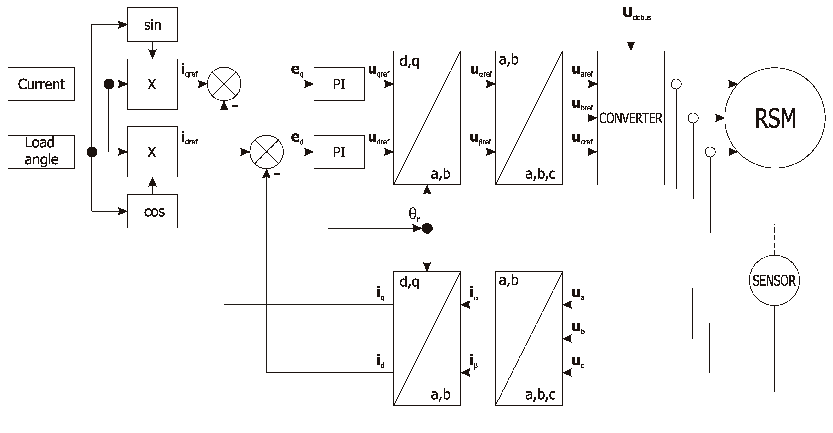
Figure 8.
Torque comparison from measurement and FEM analysis at rated current.

Figure 9.
Torque and Power Factor versus load angle at 500 rpm and rated current.

Figure 10.
Torque and Power Factor versus load angle at 1000 rpm and rated current.

Figure 11.
Torque and Power Factor versus load angle at 1500 rpm and rated current.


Table 1.
Measured and calculated parameters.
| New Designed RSM Rotor | Measured | FEM |
|---|---|---|
| Ld for current 3.4 A | 200 mH | 220 mH |
| Lq for current 3.4 A | 62 mH | 62 mH |
| Ld/Lq | 3.22 | 3.54 |
| Rs for 20 °C | 6.132 Ω | - |
| RD | 10.2 Ω | - |
| RQ | 0.89 Ω | - |
| XD | 87 Ω | - |
| XQ | 16 Ω | - |
| Temax for current 3.4 A | 10.9 Nm | 11.2 Nm |
Table 2.
Comparison of original, new designed RSM rotor and induction motor measured outputs.
| Induction Motor | Optimized RSM | |
|---|---|---|
| Is (A) | 3.4 | 3.4 |
| P (W) | 1500 | 1712 |
| TL (Nm) | 10 | 10.9 |
| speed (rpm) | 1420 | 1500 |
© 2018 by the authors. Licensee MDPI, Basel, Switzerland. This article is an open access article distributed under the terms and conditions of the Creative Commons Attribution (CC BY) license (http://creativecommons.org/licenses/by/4.0/).
Share and Cite
MDPI and ACS Style
Rafajdus, P.; Hrabovcova, V.; Lehocky, P.; Makys, P.; Holub, F. Effect of Saturation on Field Oriented Control of the New Designed Reluctance Synchronous Motor. Energies 2018, 11, 3223. https://doi.org/10.3390/en11113223
AMA Style
Rafajdus P, Hrabovcova V, Lehocky P, Makys P, Holub F. Effect of Saturation on Field Oriented Control of the New Designed Reluctance Synchronous Motor. Energies. 2018; 11(11):3223. https://doi.org/10.3390/en11113223
Chicago/Turabian StyleRafajdus, Pavol, Valeria Hrabovcova, Pavel Lehocky, Pavol Makys, and Filip Holub. 2018. "Effect of Saturation on Field Oriented Control of the New Designed Reluctance Synchronous Motor" Energies 11, no. 11: 3223. https://doi.org/10.3390/en11113223
Note that from the first issue of 2016, this journal uses article numbers instead of page numbers. See further details here.