A Comprehensive Review of Nanomaterials Developed Using Electrophoresis Process for High-Efficiency Energy Conversion and Storage Systems


Abstract
1. Introduction
2. Mechanisms of Electrophoresis Process
2.1. Flocculation by Particle Accumulation
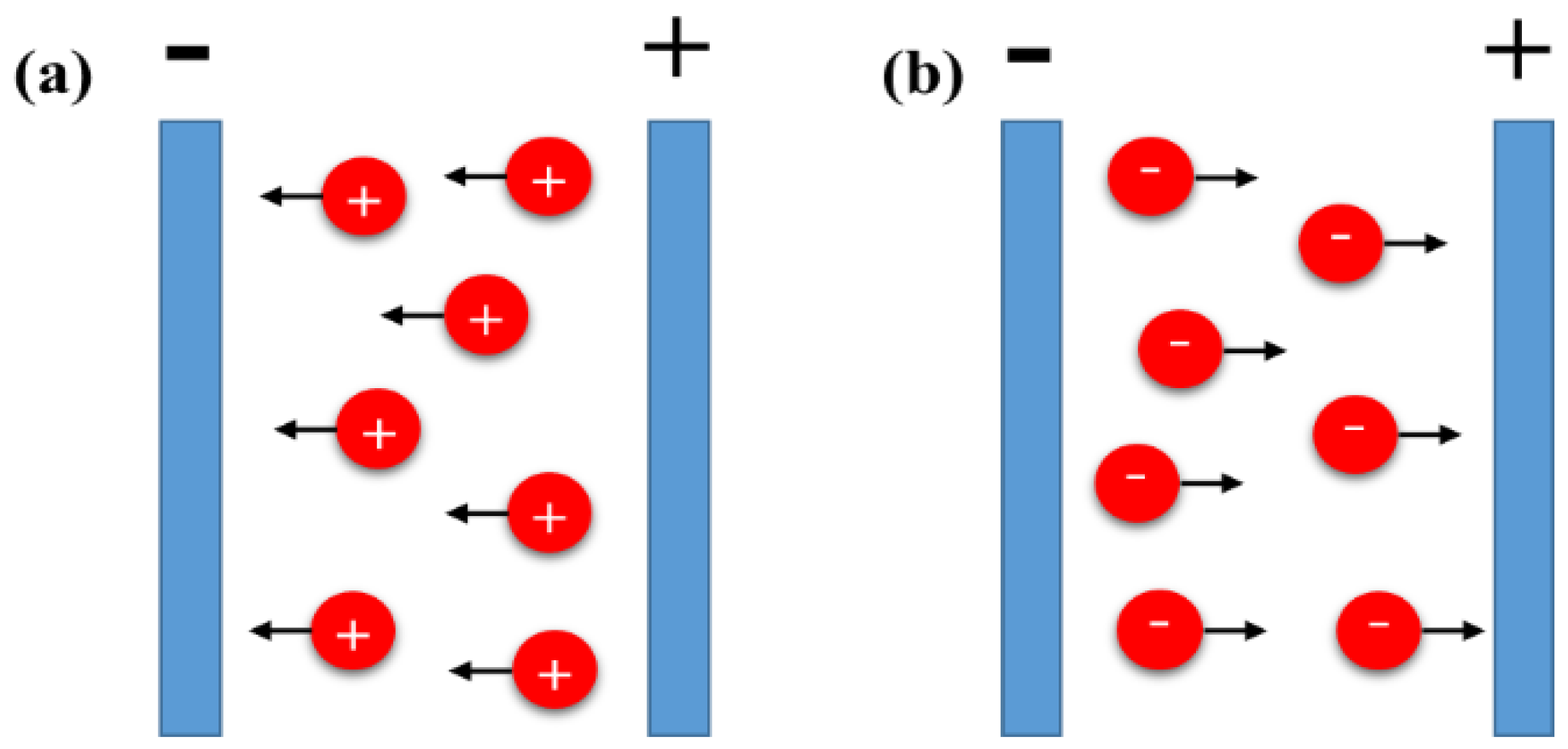
2.2. Particle Charge Neutralization
2.3. Electrochemical Particle Coagulation
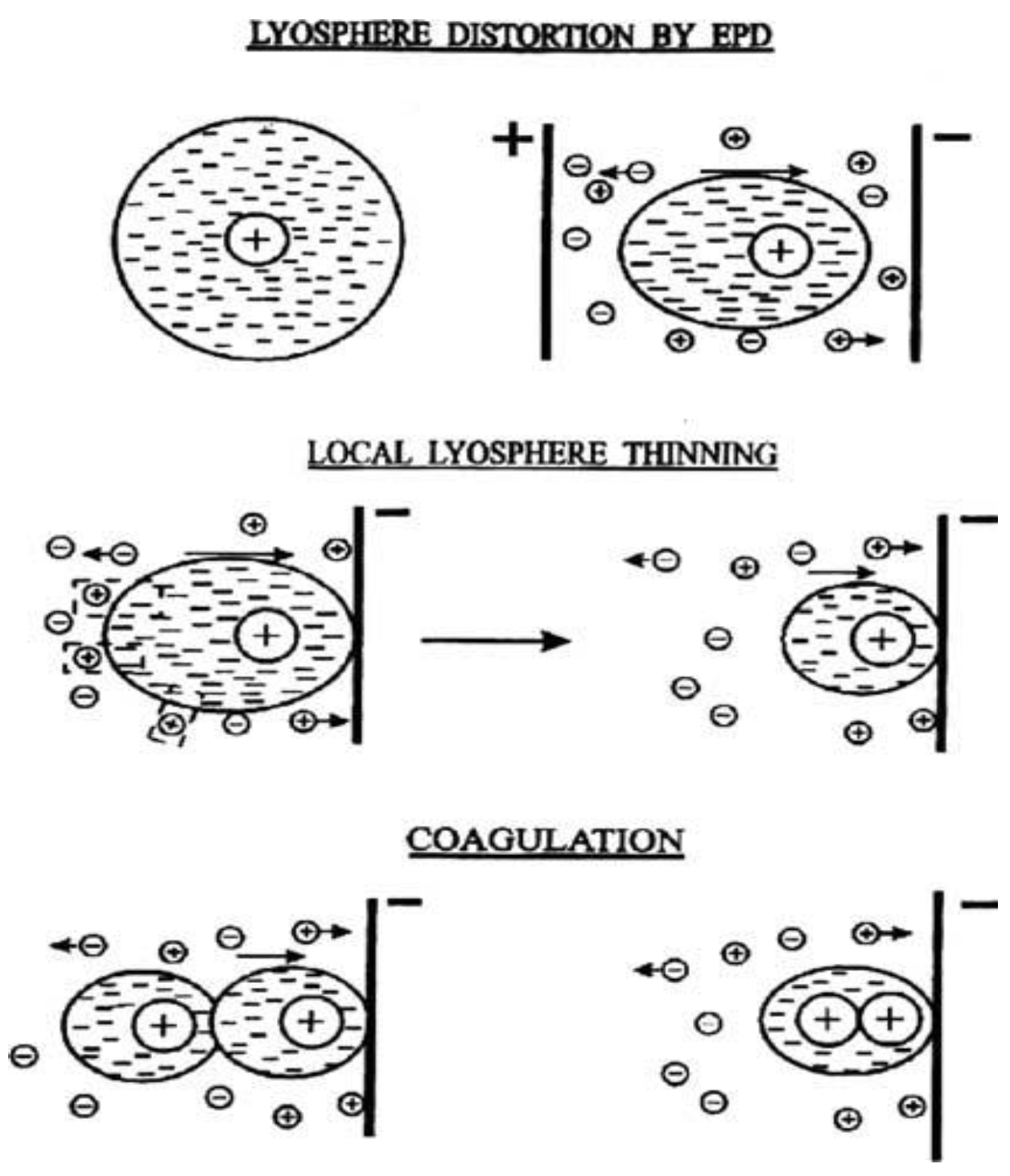
2.4. Electrical Double Layer (Edl) Distortion and Thinning
3. Principals of Electrophoresis Process
4. Factors Influencing Electrophoresis Deposition
4.1. Key Parameter Related to the Suspension
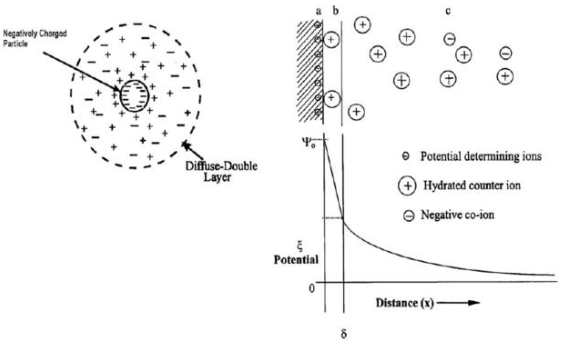
4.1.1. Zeta Potential
4.1.2. Particle Size
4.1.3. Conductivity and Viscosity of the Suspension
4.1.4. Stability of a Suspension
4.2. Key Parameters Related to the Process
4.2.1. Deposition Time
4.2.2. Applied Voltage
4.2.3. Concentration of the Solid in Suspension
4.2.4. Conductivity of the Substrate
5. Applications of the Electrophoresis Deposition for Nanomaterials of Li-Ion Batteries
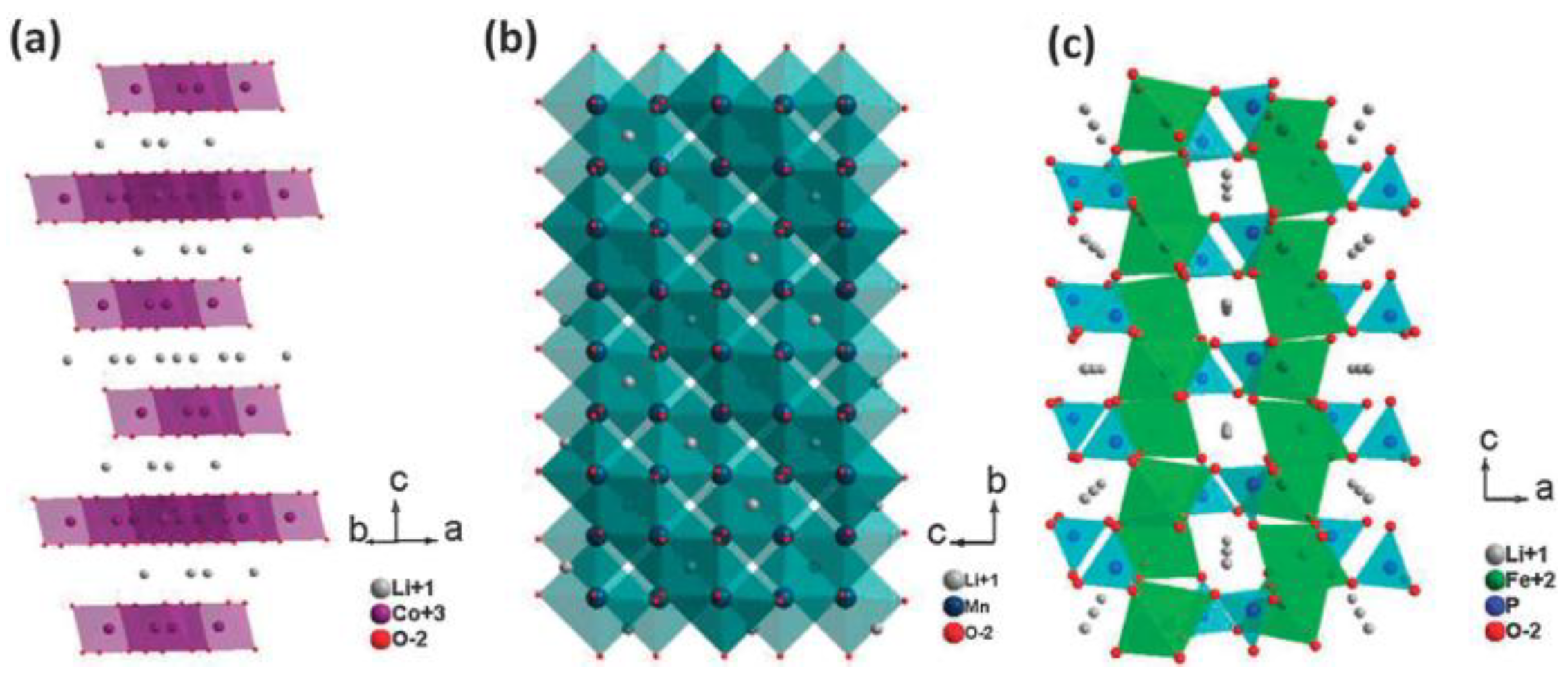
5.1. Cathode Materials
5.2. Anode Materials
5.2.1. Carbon Based Anode Materials
5.2.2. Metal Oxide-Based Anode Materials

5.2.3. Metal Oxide/Carbon Hybrid-Based Electrodes
6. Applications of the Electrophoresis Process for Nanomaterials of Supercapacitors
6.1. Carbon-Based Materials
6.2. Metal Oxide-Based Materials
6.3. Polymer/Carbon Composite Based Materials
6.4. Metal Oxide/Carbon Composite Based Materials
7. Applications of the Electrophoresis Deposition for Solid Oxide Fuel Cells
8. Applications of EPD for Nanomaterials of Electrocatalysis
9. Summary
- EPD was assessed to produce nanomaterials in energy storage devices. Oxide-based active materials are used comprehensively for the cathode electrode but their active materials have low electrical conductivity. Therefore, hybrid materials containing active and carbon materials without a binder material led to a degradation of the performance of the nanomaterials synthesized by well controlled EPD process. The hybrid materials were deposited on substrates with various structures because EPD does not influence the form of the substrates. EPD can used to deposit thin and thick films for all-solid-state-based cathode electrodes without organic additives to improve safety.
- When designing anode materials by EPD, the aim should be to minimize the volume expansion, which leads to performance degradation during lithium intercalation, and enhance the activated sites. In this regard, studies of EPD have been conducted to design uniform coatings for thin and thick films, multilayered composites, and hybrid materials. Such electrodes designed by EPD can be increased without sacrificing the performance. A study of the high performance and stability of the nanomaterials designed by EPD appears to be very promising for finding new nanomaterials with the optimal activity towards practical applications.
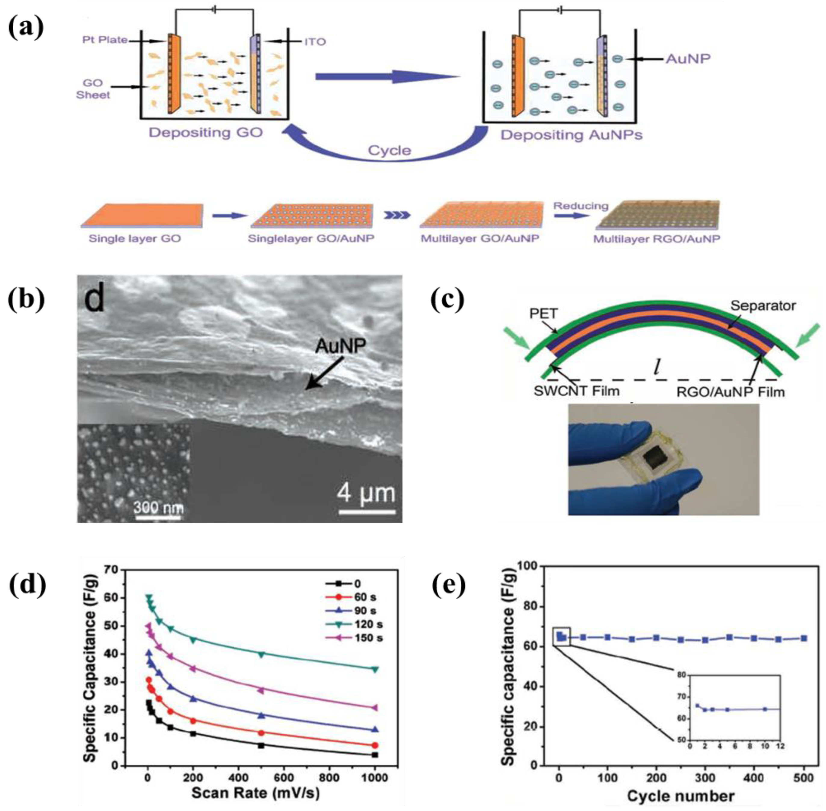
- An enhancement of the specific surface area or activated sites of nanomaterials for supercapacitor applications is the main concern. Recent studies found that the use of EPD to design and manufacture electrodes enhances the specific capacitance for supercapacitors. The uniform thin and thick films, multilayered composites, and hybrid materials have been designed by EPD to increase the specific capacitance. In particular, the specific surface area and activated sites for high specific capacitance can be improved using graphene nanosheets and carbon nanotubes during the EPD process. A high electrical conductivity can lead to enhanced specific capacitance.
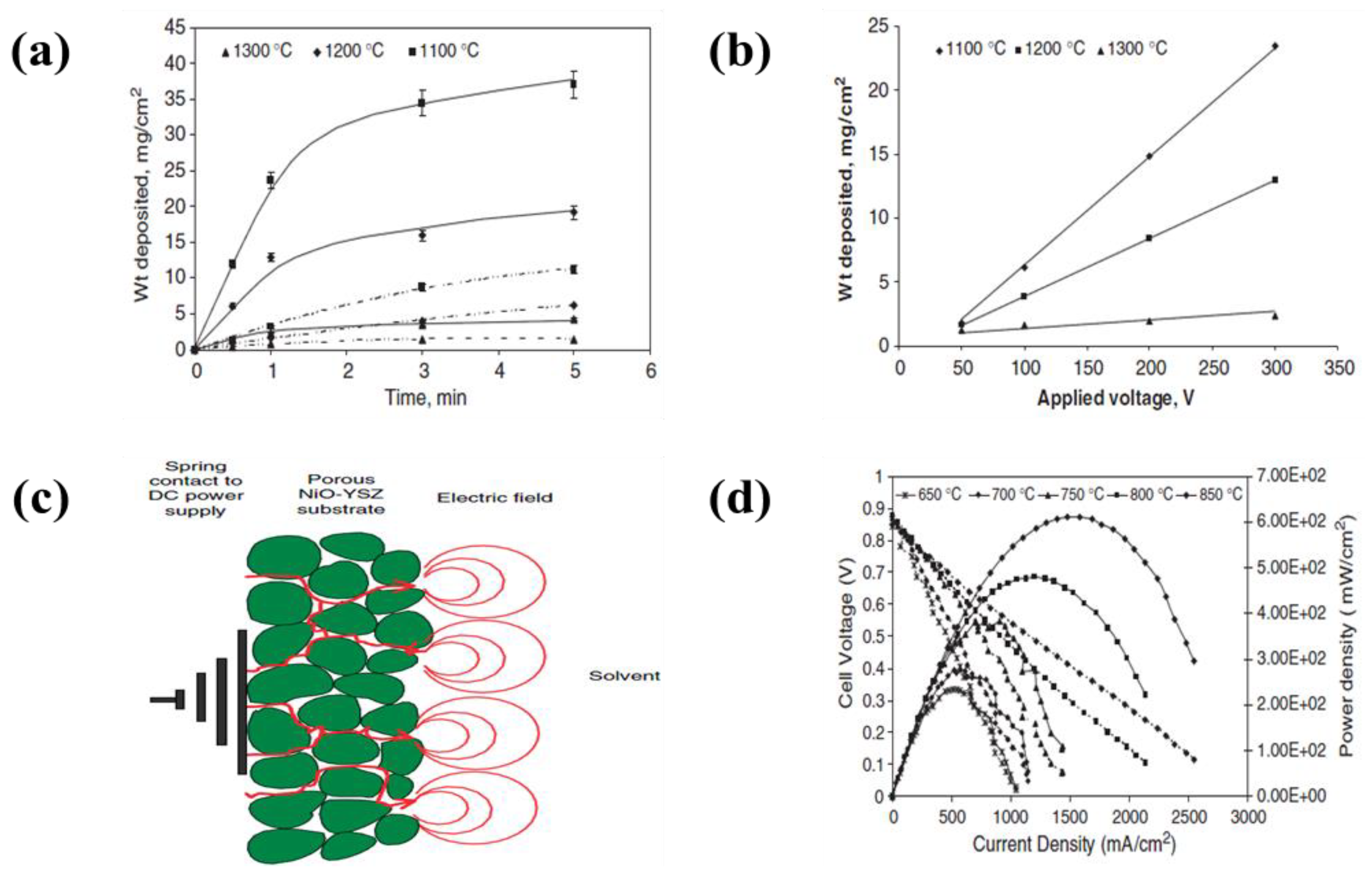
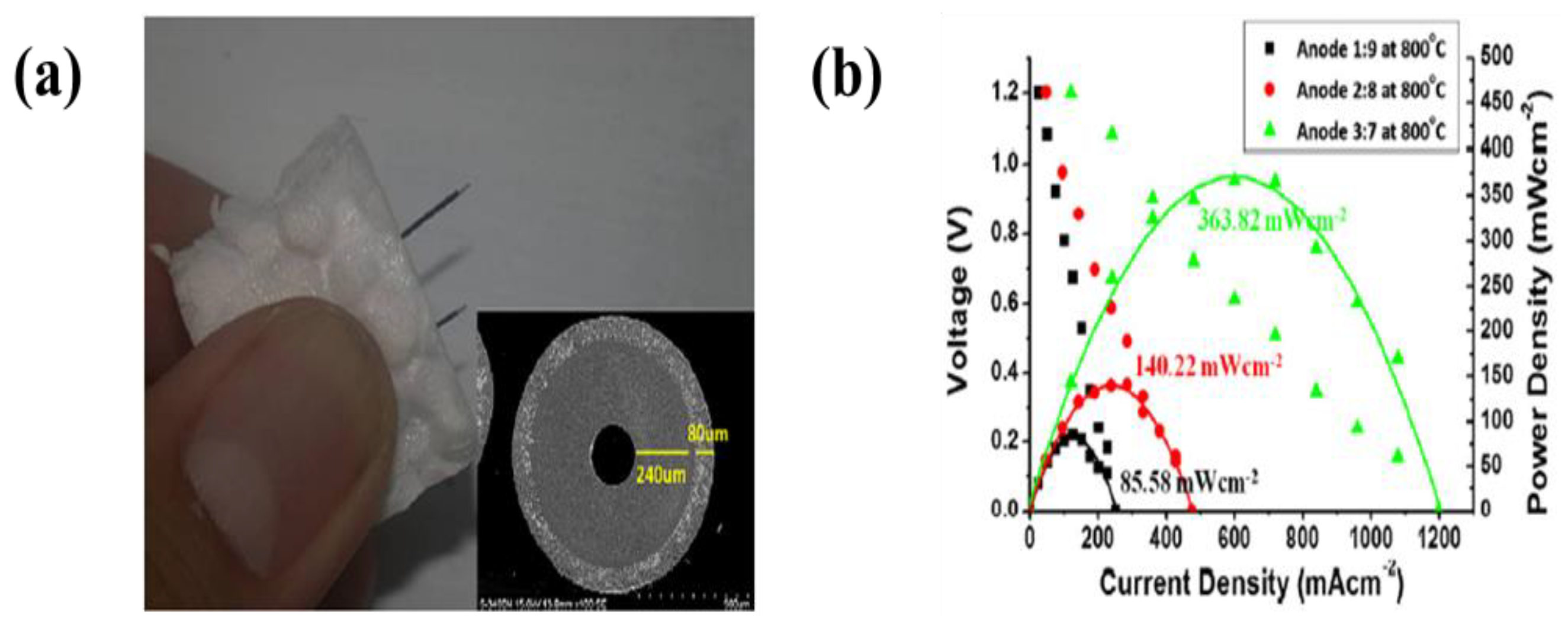
- The electrodes for solid oxide fuel cells generally need to be porous to permeate the fuel, while the electrolyte layer must be dense to prevent the leakage of gas across the layer. Electrodes have been designed with a variety of parameters, such as applied voltage, concentration of the dispersed species, and deposition time, to form highly porous and dense electrodes. The use of EPD can raise the energy density more than when a conventional process is used. Recently, EPD has been used to produce laminated ceramics because of its deposition efficiency, cost-effectiveness and ease of operation compared to other coating methods, such as lithography, self-assembly, dip coating and screen printing, and spin coating.
- Nanostructured electrocatalysts based on noble metals have been studied comprehensively for the oxidation reactions of methanol, ethanol and formic acid, and the oxygen reduction reaction. The use of EPD to design electrocatalysts or electrodes is another cost effective way to achieve fuel cell commercialization. Recently, non-precious metal electrocatalysts for the oxygen reduction reaction have been pursued actively to reduce the prohibitive price of noble metals. The nanostructured electrocatalysts fabricated by EPD for catalytic activity could be an effective way to use fuel cells.
10. Outlook
Author Contributions
Acknowledgments
Conflicts of Interest
Appendix A

| No. | Materials | Suspension Medium | EPD Conditions | Specification (Charge/Discharge Capacity) | Ref. | ||
|---|---|---|---|---|---|---|---|
| Coating | Substrate | Voltage | Time | ||||
| 1 | LiCoO2 | Al foil | Acetone, I2, PTEF, and ketjen black (C∙A) | 100 | 1 min | A specific capacity of 142 mAh·g−1, maintained a capacity of 120 mAh·g−1 after 20 cycles | [30] |
| 2 | LiMn2O4 | Al foil | Acetone, I2, PTEF, and ketjen black (C∙A) | 400 | 1 min | A specific capacity of 110 mAh·g−1, maintained a capacity of 75 mAh·g−1 after 20 cycles | [74] |
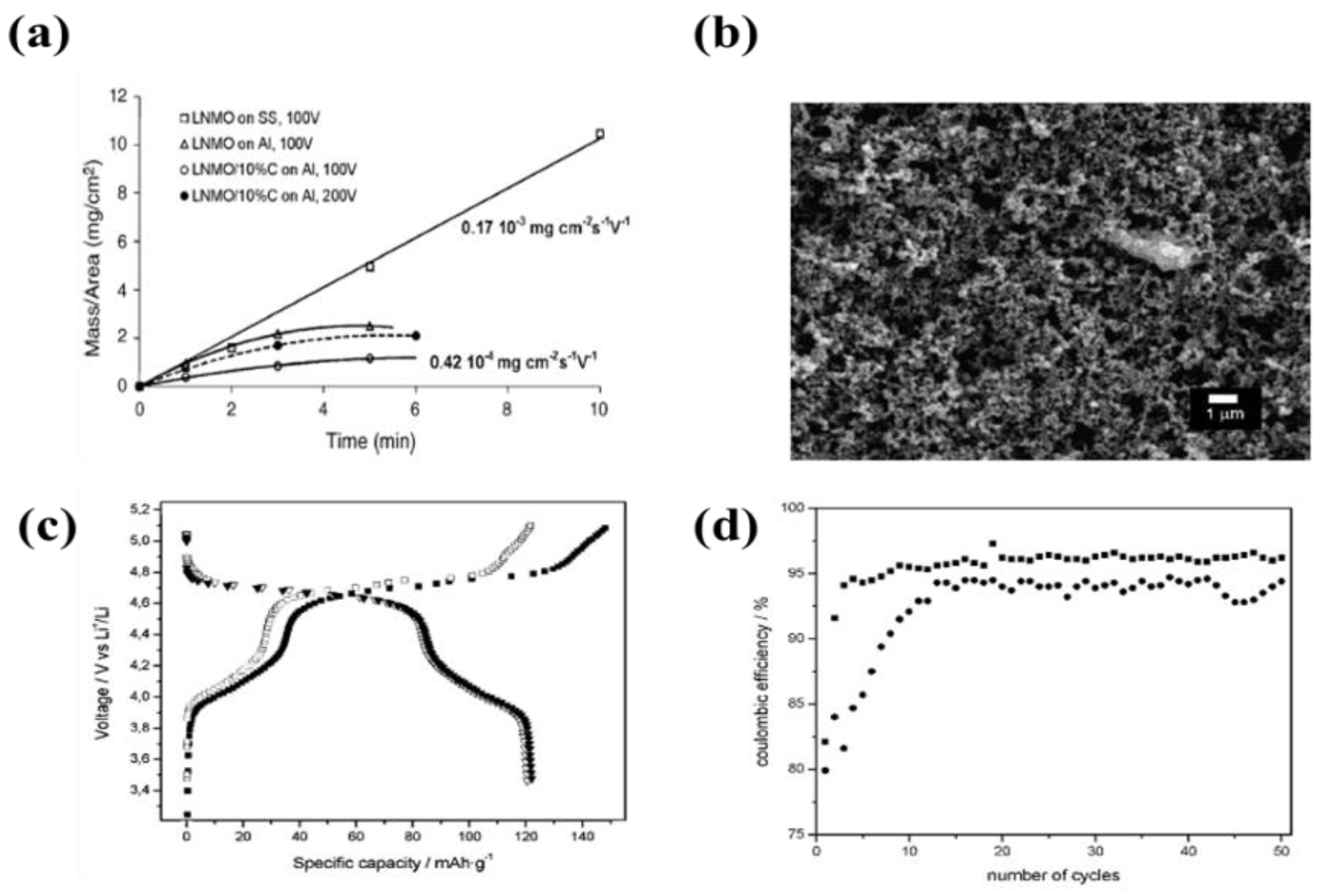
| 3 | LiNi0.5Mn1.5O4 | Al foil and SS | Acetone or ethanol, polyethyleneimine (PEI), citric acid, and ketjen black (C∙A) | 0.15–4 µA·cm−1 | 10 min | A specific capacity of 122 mAh·g−1 with coulombic efficiency of 95–97% after 50 cycles | [75] |
| 4 | LiNi0.5Mn1.5O4 | Al disk | Aceton, PVP, citric acid, PVB, and carbon black (C∙A) | 100 | 5 min | A specific capacity of 130 mAh·g−1, maintained the capacity after 20 cycles | [76] |
| 5 | Li[Ni1/3Co1/3Mn1/3]O2 | Al foil | Aceton, PVDF, and I2, denka black (C∙A) | 60 V | 1 min | A specific capacity of 147.18 mAh·g−1, 97.11% capacity retention after 50 cycles at 0.2 C-rate. | [77] |
| 6 | LiCoPO4 | Ti plate | IPA and LiCl | 60 V | 30 min | A specific capacity of 103 mAh·g−1 with coulombic efficiency of 55% after 10 cycles | [82] |
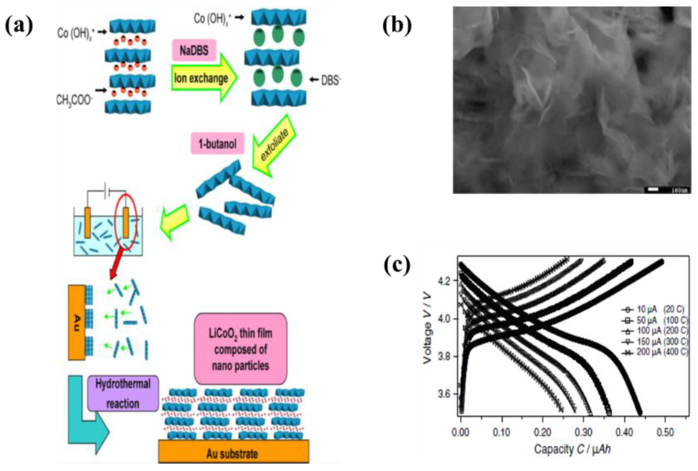
| 7 | LiCoO2 | Au | 1-butanol and cobalt hydroxide nanosheet | 20 µA·cm−1 | 5–40 min | A utilization efficiency of the discharge capacity sustained 74% efficiency over 200 C-rate | [88] |
| 8 | LiFePO4 | 3D-Ni disk | Acetone, I2, PVDF, non-ionic surfactant triton X-100 and ketjen black (C∙A) | 60–100 V | 1–2 min | A peak-pulse-power capability of 200 mW·cm−2 and an energy density of 6–10 mWh·cm−2 | [89] |
| 9 | LiMnPO4 | Al foil | Isopropanol and nickel nitrate | 50 V | 60 min | A specific capacity of 83 mAh·g−1, 86% capacity retention after 30 cycles at 1 C rate | [90] |
| 10 | LiFePO4/reduced graphene oxide | Carbon cloth | IPA, Mg(NO3)2∙6H2O | 90 V | - | A specific capacity of 174.7 mAh·g−1 at 0.2 C | [91] |
| No. | Materials | Suspension Medium | EPD Conditions | Specification (Charge/Discharge Capacity) | No. | ||
|---|---|---|---|---|---|---|---|
| Coating | Substrate | Voltage | Time | ||||
| 1 | Si nanoparticles/AB | Cu foil | Citric acid monohydrate, acetone | 120 V | 5–60 s | An initial capacity of 3150 mAh·g−1 and remained the capacity of 2175 mAh·g−1 after 50 cycles at 0.1 C-rate | [92] |
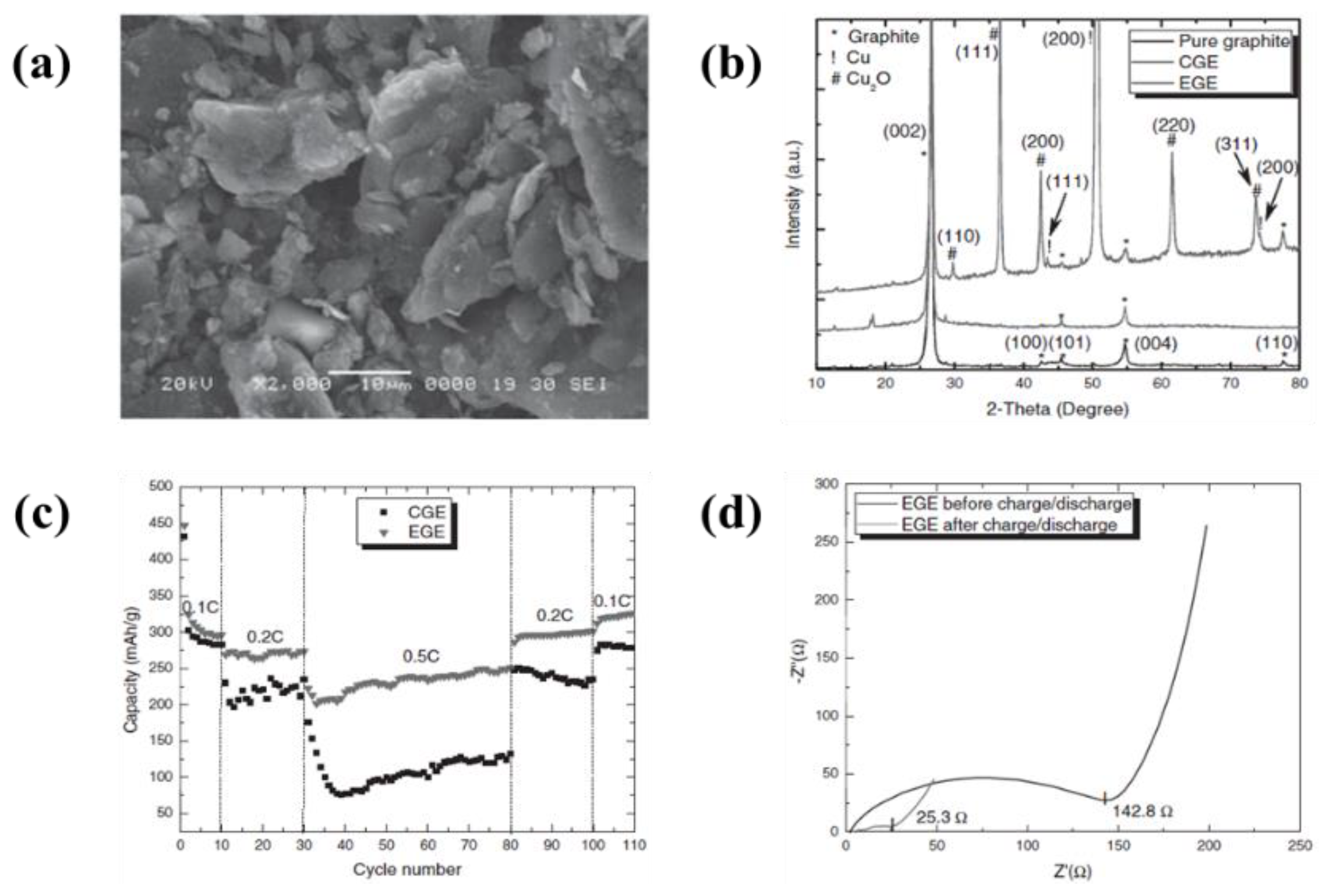
| 2 | Artificial graphite, natural graphite, soft carbon, and hard carbon | Mo foil | Acetonitrile, triethylamine (TEA), tetramethylguanidine (TMG), and pyridine (Py). | 0–500 V | 10–60 s | A reversible capacities of 296–395 mAh·g−1 with a coulombic efficiency of 90% after 30 cycles | [96] |
| 3 | Graphite | Cu foil | Acetonitrile, triethylamine (TEA), tetramethylguanidine (TMG), and pyridine (Py). | 24 V | 15 min | A reversible capacities of 330 mAh·g−1 at 0.2 C, maintained the capacity after 30 cycles | [98] |
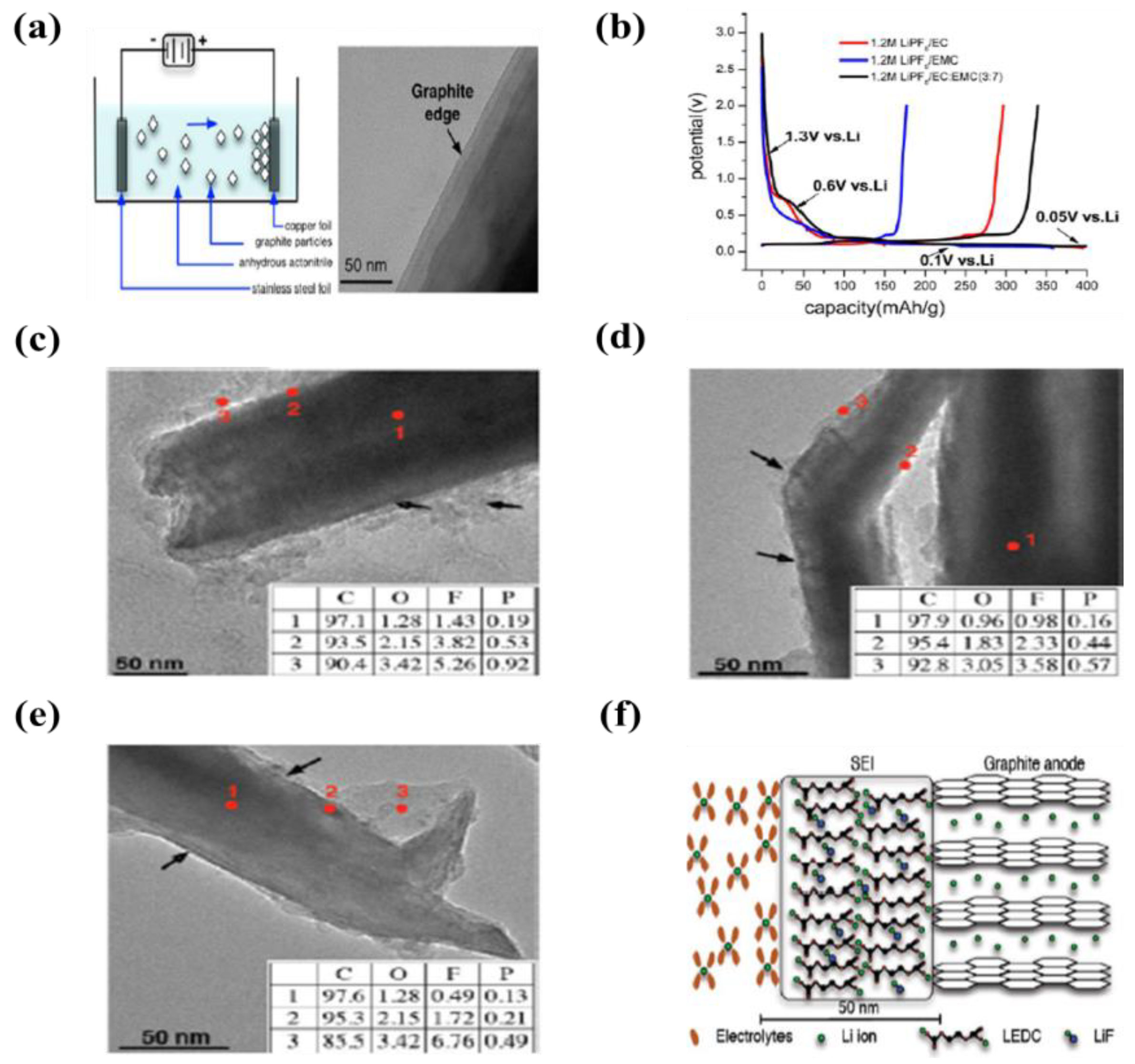
| 4 | Graphite | Cu foil | Acetonitrile and triethylamine (TEA) | 50 V | 2 min | An initial capacities were 400, 360, and 400 mAh·g−1 at LiPF6/EC, LIPF6/EMC, LIPF6/EC/EMC (3:7 v/v), respectively | [105] |
| 5 | Graphite | Cu foil | Acetonitrile and triethylamine (TEA) | 32 V | 1 min | An initial capacities were 450 and 550 mAh·g−1 at LiPF6 and LiF2BC2O4, respectively | [106] |
| 6 | Graphite | Cu foil | Acetonitrile and triethylamine (TEA) | 32 V | 1 min | An initial capacities were 450, 520, 620, and 620 mAh·g−1 at LiPF6, LiBOB, LiBF4, and LiF2BC2O4, respectively | [107] |
| 7 | Graphite | Cu foil | Acetonitrile and triethylamine (TEA) | 32 V | 1 min | An initial capacities were 375, 370, and 320 mAh·g−1 at LiTFSI, LIFSI, and LiDFOB dissolved in EC, respectively | [108] |
| 8 | Graphene nanosheet | Stainless steel | Ni(NO3)2 in isopropyl alcohol (IPA) | 100 V | 10 min | A reversible discharge capacity of 392 mAh·g−1 in initial cycle and stabilized the capacity of 200 mAh·g−1 after 20 cycles at 0.2C. | [115] |
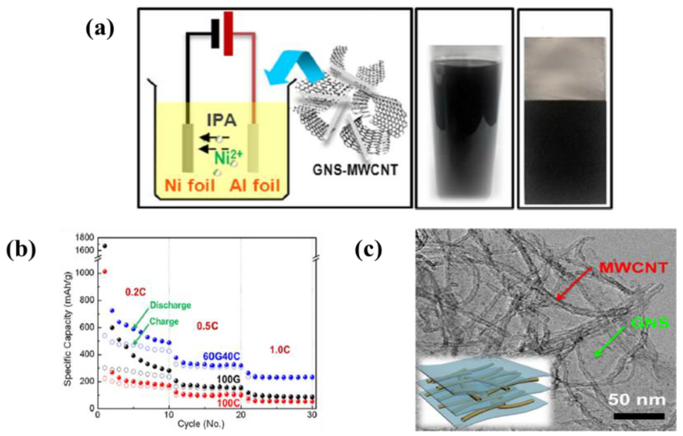
| 9 | MWCNTs/Graphene nanosheet | Al foil | Ni(NO3)2 in isopropyl alcohol (IPA) | 100 V | 10 min | A specific discharge capacity of 2200 mAh·g−1 in initial cycle and stabilized 458 mAh·g−1 after 10 cycles at 0.2C | [117] |
| 10 | MoOx nanoparticles | Stainless steel | Methanol | 300 V | 1–2 min | A reversible capacity of 630 mAh·g−1 and 93% capacity retention after 150 cycles at 0.5 C rate | [131,132,133] |
| 11 | V2O5 nanoparticles | ITO | Water | 5 V | - | A specific capacity of 300 mAh·g−1 of 50 µAh·cm2 and maintained the good capacity after 50 cycles | [134] |
| 12 | TiO2 nanosheet | Pt coated Si wafer | Water | 5 V | - | A specific capacity of 190 mAh·g−1 at 3.85 µAh·cm2 | [135] |
| 13 | TiO2 nanosheet | Pt coated Si wafer | Water | 5 V | - | A reversible capacity of 170 mAh·g−1 when cycled between 0.8 and 3.2 V | [136] |
| 14 | TiO2 nanoparticles | 3D-Al | Ethanol, PE169, and Butvar | 50 V | 1–2 min | - | [137] |
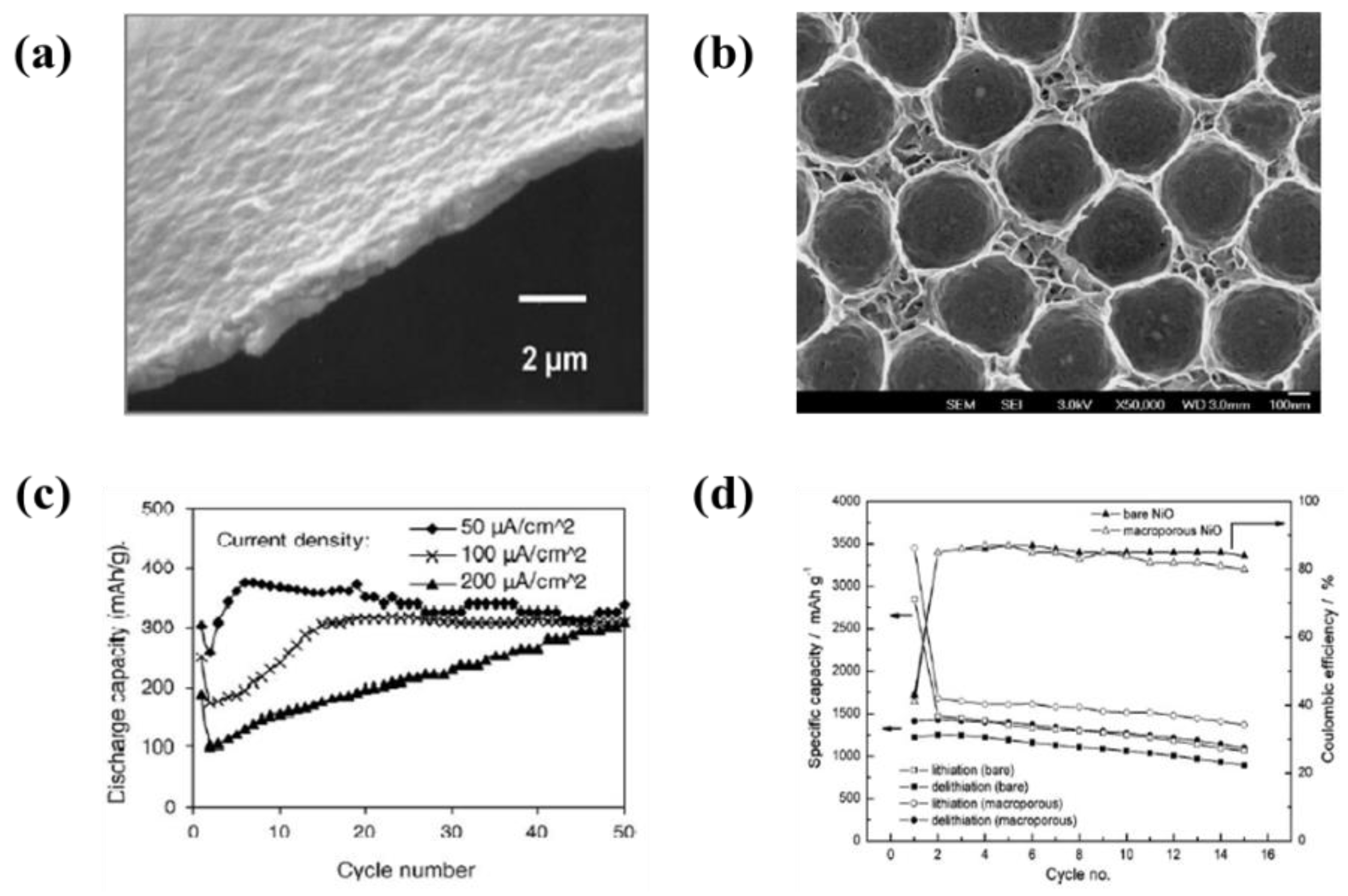
| 15 | Polystyrene sphere/NiO2 | Stainless steel | water | 60 V | 2 min | A specific capacity of 1620 mAh·g−1 at 1 C-rate and 990 mAh·g−1 at 15 C-rate | [138] |
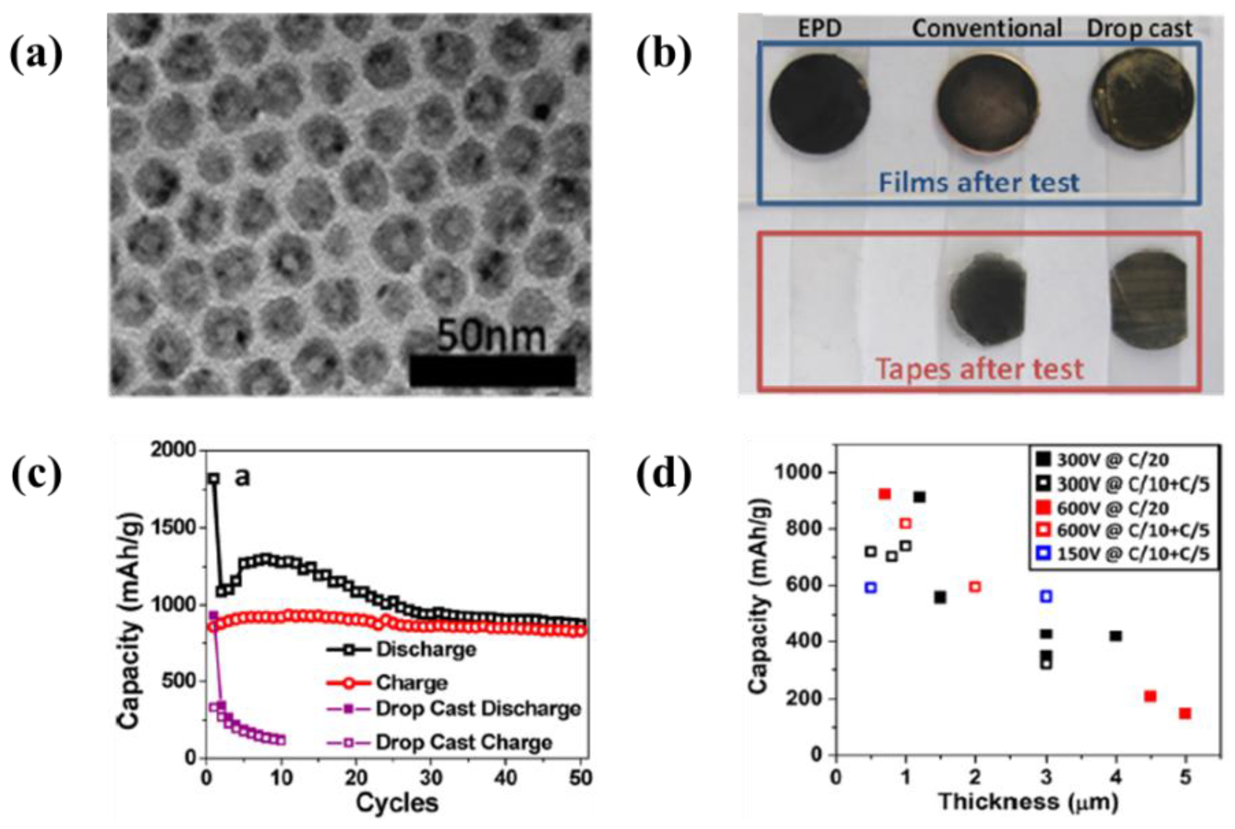
| 16 | Hollow structured Co3O4 nanoparticles | Cu foil | Hexane | 150–600 V | 10–30 min | A reversible specific capacity of 1820 mAh·g−1, remained the capacity of 890 mAh·g−1 after 50 cycles at 0.05 C-rate | [139] |
| 17 | Hollow structured Co3O4 nanoparticles | SiO2/Si | Hexane | 1500 V | - | A specific capacity of 1300 mAh·g−1 in the first discharge as a current density of 100 mA·g−1 and stabilized 800 mAh·g−1 after 3 cycles | [140] |
| 18 | SnO2 nanoparticles-AB | Cu foil | Aceton and Acetylene Black | 100 V | 10 s | A initial capacities were 887 mAh·g−1 at 0.1 C-rate and remained the capacity of 504 mAh·g−1 after 50 cycles | [140] |
| 19 | MnO2-MWCNTs | Ni foil | Ethanol and sulfuric acid | 50 V | 5 min | A specific capacity of 741 mAh·g−1 for first cycle and 407 mAh·g−1 after 20 cycle at 120 mA·g−1 current density | [149] |
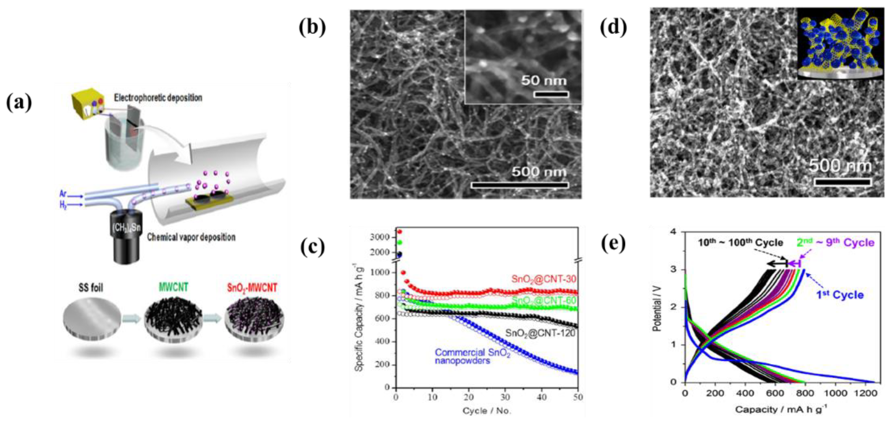
| 20 | SnO2-MWCNTs | Stainless steel | Isopropyl alcohol (IPA) and Ni salt | 100 V | 10 min | A reversible capacity of 780, 510, and 470 mAh·g−1 at 1 C-rate after 100, 500, and 1000 cycles, respectively | [150] |
| 21 | CoO-MWCNTs | Stainless steel | Isopropyl alcohol (IPA) and Ni salt | 100 V | 2 min | A reversible capacity of 600 and 550 mAh·g−1 at the rate of 715 mA·g−1 after 50 and 100 cycles, respectively | [151] |
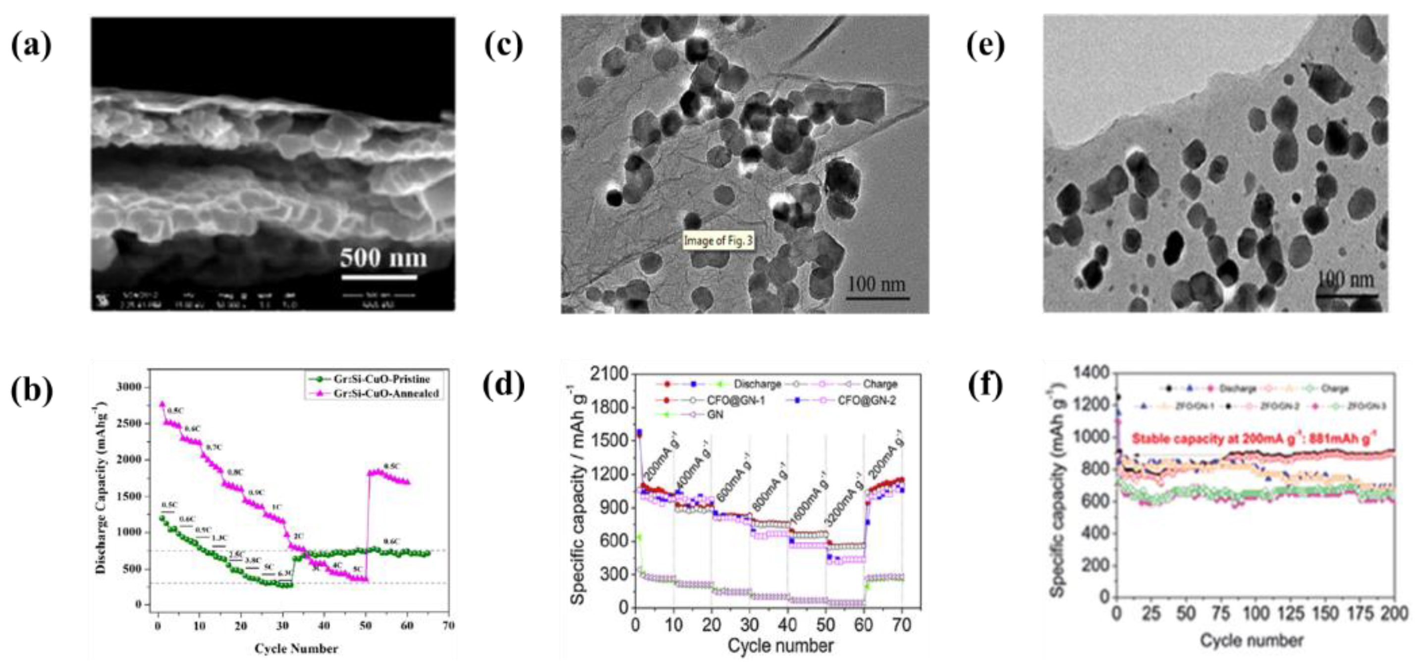
| 22 | Multi layered Graphene-Si-CuO | Cu foil | 1 step: water 2 step: water and HF | 10 V | 1 min | A initial capacity of 2869 mAh·g−1 at 0.5 C-rate and the capacity retention of 71% after 100 cycles at 1 C-rate | [152] |
| 23 | Graphene-ZnFe2O4 nanoparticles | Cu foil | Fe(NO3)3∙9H2O and Zn(NO3)2∙6H2O suspension | 60 V | 5 min | A initial capacities were 910 mAh·g−1 at 200 mA·g−1 and remained the capacity of 881 mAh·g−1 after 200 cycles | [153] |
| 24 | Graphene-CoFe2O4 nanoparticles | Cu foil | Fe(NO3)3∙9H2O and Co(NO3)2∙6H2O suspension | 60 V | 400 s | A specific capacity of 865 mAh·g−1 at 1000 mA·g−1 and remained the capacity after 200 cycles | [154] |
| 25 | Graphene-TiO2 nanotubes | TiO2 nanotubes | - | 4 V | 30 min | An initial capacity of 1100 mAh·g−1 when cycled between 0.01 and 3V at 0.1 mA·g−1 | [155] |
| 26 | Ge-MWCNTs | Stainless steel | Isopropyl alcohol (IPA) and Ni salt | 100 V | 2 min | A reversible capacity of 1240, 960, 810, 620 and 490 mAh·g−1 at 0.5, 1, 2, 3, and 5 C-rates, respectively | [161] |
| 27 | Sn-MWCNTs | Stainless steel | Isopropyl alcohol (IPA) and Ni salt | 100 V | 2 min | A specific capacity of 2100 mAh·g−1 and irreversibility stabilized around 700 mAh·g−1 after 100 cycles | [162] |
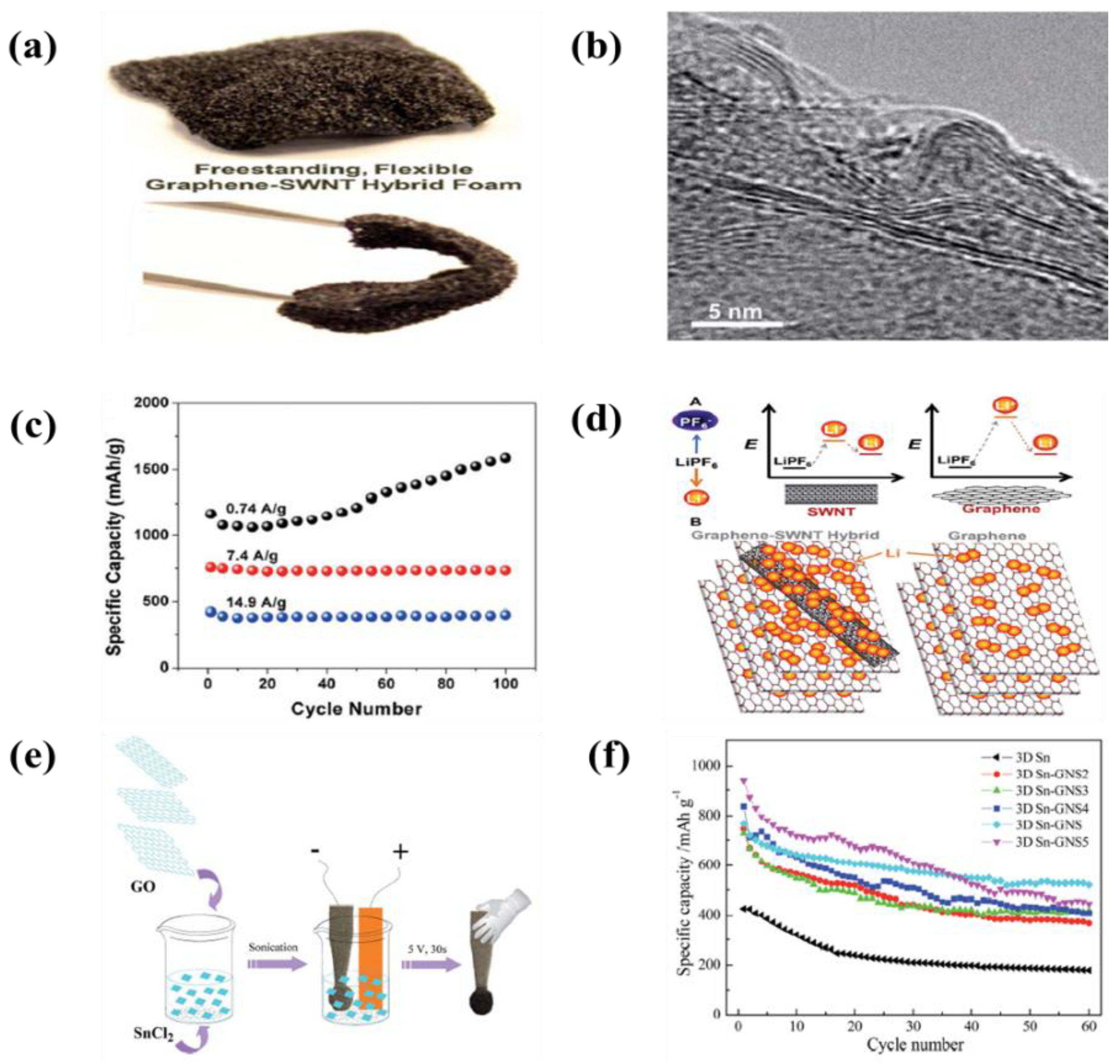
| 28 | Graphene-Sn nanoparticles | Cu foil | Isopropyl alcohol (IPA) and Mg(NO3)2∙H2O | 300 V | 30 min | A specific capacity of 733, 535, 466, 417, and 417 mAh·g−1 at 100, 200, 500, and 1000 mA·g−1, respectively | [163] |
| 29 | Si nanoparticles | Cu foil | Acetonitrile and triethylamine (TEA) | 32 V | 1 min | An initial capacities of 1800 and 1700 mAh·g−1 at LiPF6/EC and LiPF6/FEC, respectively | [164] |
| 30 | Carbon nanoparticles | Dendritic Sn foams | Ethanol and sulfuric acid | 70 V | 10 s | A reversible capacities of about 600–300 mAh·g−1 at 99.1 mA·g−1 with a coulombic efficiency of 90% after 30 cycles | [169] |
| 31 | Sn-garphene | Ni form | HCl, SnCl2∙H2O | 5 V | 30 s | An initial capacity of 964 mAh·g−1 and remained the capacity of 520 mAh·g−1 after 60 cycles | [170] |
| 32 | Graphene-SWCNTs | Ni form | NMP | 40 V | - | A reversible capacity of 2640 mAh·g−1 and 236 mAh·g−1 at 0.5 and 75 C, respectively | [171] |
| 33 | SWCNTs | Ni form | NMP | 30 V | - | A reversible capacity of 2210 mAh·g−1 with energy efficiencies up ~50% and cycling behavior greater than 500 cycles | [173] |
| 34 | Ge-acetylene black | Ni form | Isopropyl alcohol (IPA) GeCl4 | 100 V | 2 min | A specific capacity of 924 mAh·g−1 after 100 cycles at 0.1 C-rate | [177] |
| 35 | Reduced graphene oxide | Stainless steel | Water | 30 V | - | A specific discharge capacity of 1120 mAh·g−1 as a constant current density of 1 mA·cm−2 and 85% capacity retention after 50 cycles | [333] |
| 36 | Li4Ti5O12 | Cu foil | Acetonitrile, Ketjen Black, I2, and polyethyleneoxide | 100 V | 2 min | A specific capacity of 149 mAh·g−1 at 0.1 C-rate and 85% of its theoretical capacity | [334] |
| 37 | A-Fe2O3-carbon nanofiber | Stainless steel | Ni(NO3)2 and isopropyl alcohol (IPA) | 40 V | 30 s | A specific capacity of 1850 and 970 mAh·g−1 at 1 and 10 C-rate, respectively | [335] |
| 38 | β-Ni(OH)2 | Cu foil | Ni(OH)2, carbon black, and ethylic | 5 mA·cm−2 | 10–30 min | An initial capacity of 1400 mAh·g−1 and remained the capacity of 600 mAh·g−1 after 30 cycles | [336] |
| 39 | Carbon nanofiber/Mn3O4 coaxial nanocalbles | Carbon nanofiber | Mg(NO3)2∙6H2O | 10 V | 120 min | An initial capacity of 1690 mAh·g−1 at a current density of 100 mA·g−1 and remained the capacity of 760 mAh·g−1 after 50 cycles | [337] |
| 40 | Carbon Carbon nanofiber/NiO core-shell nanocables | Carbon nanofiber | Ni(NO3)2∙6H2O | 10 V | 120 min | An initial capacity of 1400 mAh·g−1 and remained the capacity of 825 mAh·g−1 after 50 cycles at a current density of 200 mA·g−1 | [338] |
| 41 | Flower-like Co3O4/carbon nanofiber core shell | Carbon nanofiber | Co(NO3)2∙6H2O | 10 V | 120 min | An initial capacity of 1446 mAh·g−1 and remained the capacity of 911 mAh·g−1 after 50 cycles at a current density of 200 mA·g−1 | [339] |
| 42 | Ge/CNTs | Cu foil | Ni(NO3)2∙6H2O and IPA | 100 V | 2 min | An initial capacity of 1442 mAh·g−1 and remained the capacity of 810 mAh·g−1 after 100 cycles at a current density of 0.2 C-rate | [340] |
| GeCl4 including ionic liquid | - | - | |||||
| 43 | Fe3O4/CNTs/rGO | Cu foil | Acetone and I2 | 100 V | 15 s | A specific capacity of 540 mAh·g−1 at a very high current density of 10 A·g−1 | [341] |
| No. | Materials | Suspension Medium | EPD Conditions | Specification (A specific Capacitnace) | Ref. | ||
|---|---|---|---|---|---|---|---|
| Coating | Substrate | Voltage | Time | ||||
| 1 | Nanoscale activate carbon | Ti foil | Isopropyl alcohol (IPA) and Ni salt | 100 V | - | A specific capacitance of 1071 F·g−1 at 100 mV·s−1 and area capacitance of 0.48 F·cm−2 | [184] |
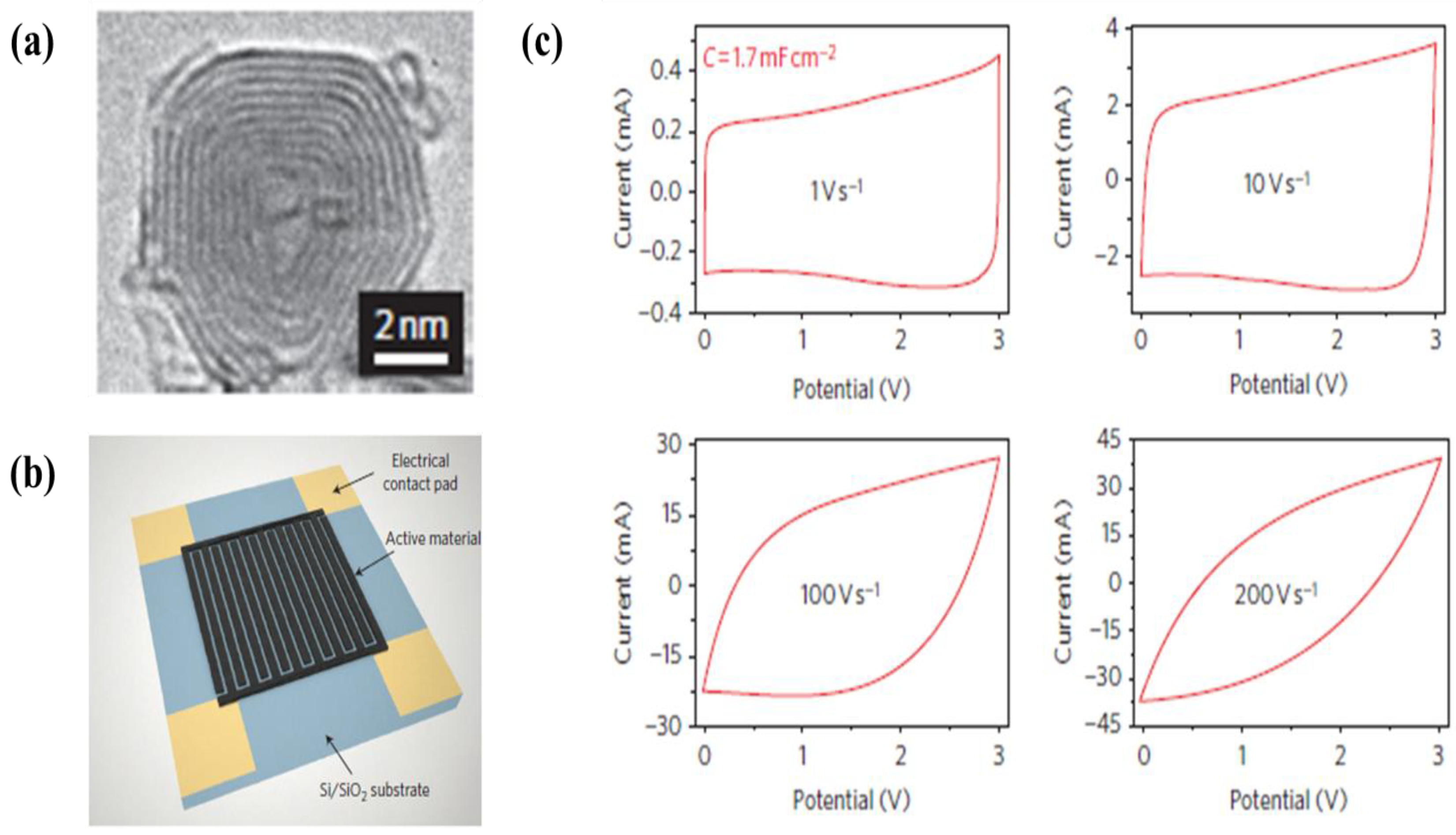
| 2 | Onion like carbon | Au coated Si wafer | Ethanol, water, MgCl2 active carbon | 50 V | - | A specific capacitance of 0.9 mF·cm−2 at 100 V·s−1 | [185] |
| 3 | Onion like carbon | Au coated Si wafer | Ethanol, water, and MgCl2 | 50 V | - | A specific capacitances of 1.1 mF·cm−2 and 0.84 mF·cm−2 at 20 and −50 °C at 10 mV·s−1, respectively | [186] |
| 4 | SWCNTs | Ni form | NMP | 40 V | - | A specific capacitance of 83 F·g−1 at 0.1 A·g−1 with energy density of ~25 Wh·kg−1 | [171] |
| 5 | MWCNTs | Ni foil | Ethanol and Mg(NO3)2∙6H2O | 40–50 V | - | A maximum specific capacitance 21 F·g−1 at a scan rate of 500 mV·s−1 and no degradation after 100 cycles | [192] |
| 6 | MWCNTs | Ni foil | Ethanol and Mg(NO3)2∙6H2O | 40–50 V | - | A maximum specific capacitance 21 F·g−1 at a scan rate of 0.78 mA·cm−1 and no IR drop due to the hydrogen treatment | [194] |
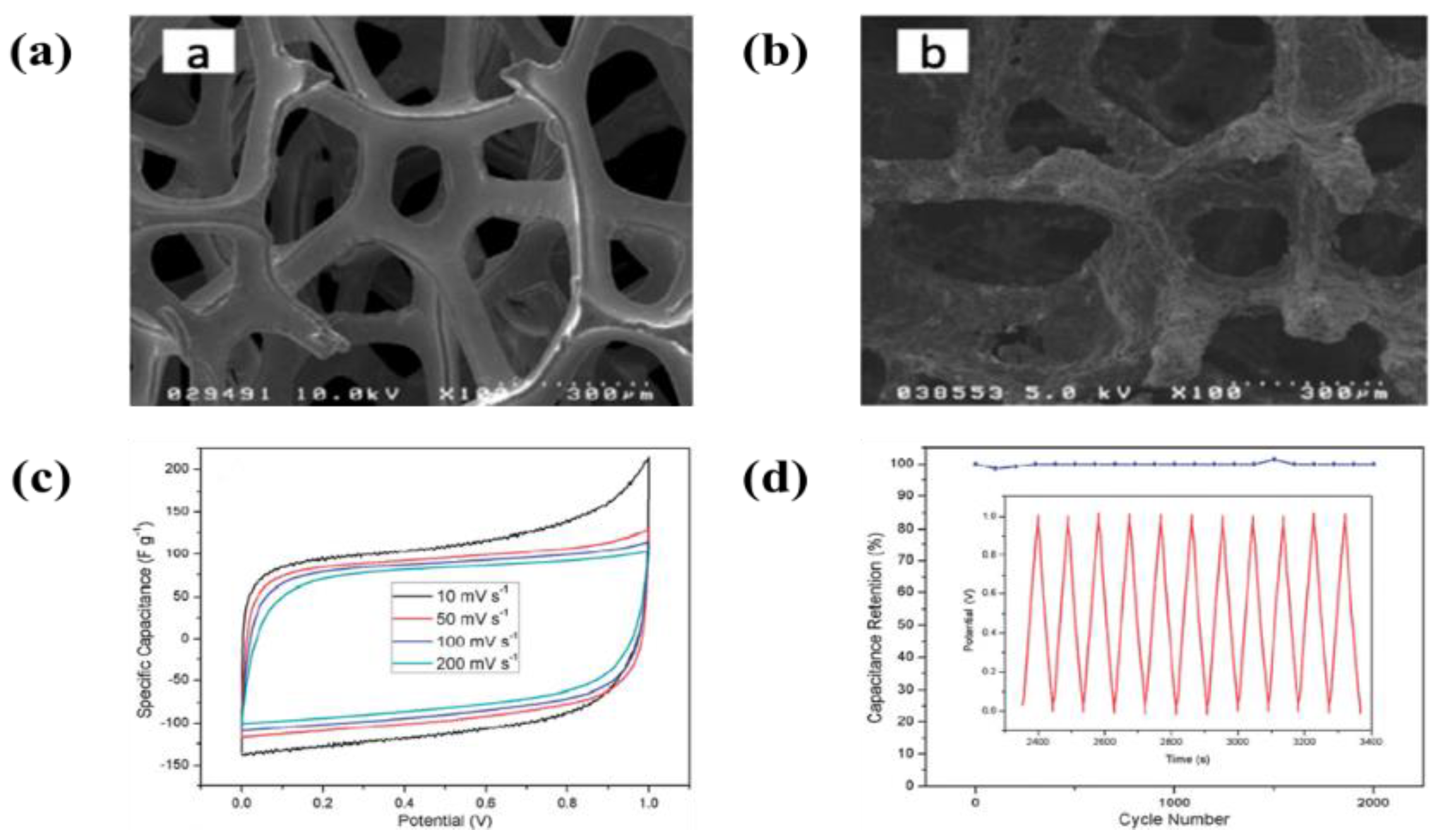
| 7 | SWCNTs | Stainless steel | Water | 10–50 V | 1–60 min | Specific capacitances of 0.16, 3.12, 5.16, 7.40, 12.53, 18.57 and 26.50 mF·cm−2 at 20 mV·s−1 for 0, 3, 5, 8, 15, 30 and 60 min of EPD processing times, respectively | [195] |
| 8 | MWCNTs | Au coated Si wafer | Water | 50 V | 30–60 s | A specific capacitance of 1.8 mF·cm−2 in the PVA-H3PO4-SiWA solid electrolyte | [196] |
| 9 | MWCNTs | ITO coated glass | IPA and Mg(NO3)2 | 80 V | 30 s | A specific capacitance of 60 F·g−1 at a scan rate of 2 mV·s−1 in 0.5 M Na2SO4 electrolyte | [235] |
| 10 | MWCNTs | Micro-device | Water | 100 V | 30 s | A specific capacitance of 0.2 mF·cm−2 at a scan rate 10 V·s−1 in 0.5 M Na2SO4 electrolyte | [342] |
| 11 | Aligned MWCNTs | Stainless steel | Mg(NO3)2∙6H2O in isopropyl alcohol (IPA) | 150 V | 1 min | A maximum capacitance of 512 µF·cm−2 at a constant current density of 2 mA·cm−2 | [343] |
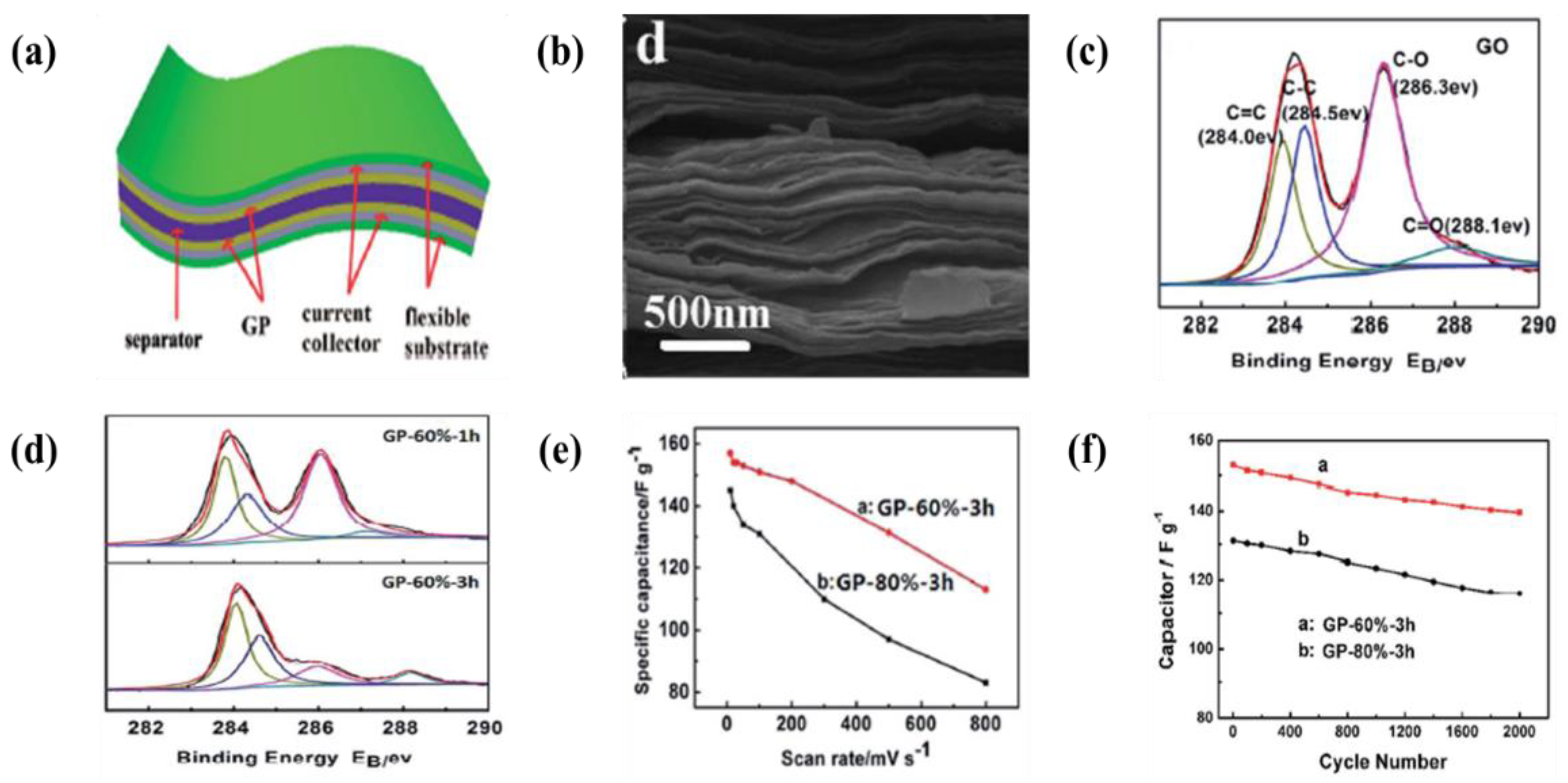
| 12 | Graphene | ITO glass | Water | 150 V | 45 s | A specific capacitance of 156 F·g−1 was achieved at 750 mA·g−1 and the capacitive retention was about 78% after 400 cycles in Na2SO4 electrolyte | [344] |
| 13 | Graphene-MWCNTs | Graphite paper | Acetone, Ethanol, and Al(NO3)3∙9H2O | 30 V | 5 min | A maximum capacitance of 87 F·g−1 at a scan rate of 5 mV·s−1 in 60graphene/40MWCNTs electrode | [345] |
| 14 | Graphene | Cu foil | Water | 5 Hz, 60 V | 1–3 h | A specific capacitance of 157 F·g−1 at a scan rate of 10 mV·s−1 and 91.3% specific capacitance retention after 2000 cycles at a scan rate of 100 and 1414 mV·s−1 | [204] |
| 15 | Reduced graphene-MWCNTs | Carbon cloth | Water | 6 V | 10 h | A maximum capacitance of 151 F·g−1 at 1 A·g−1 and 99.1% specific 16 capacitance retention after 2000 17 cycles | [200] |
| 16 | Reduced graphene-carbon black | Stainless steel | Water (pH 9) | 6 V | 10 min | A specific capacitance of 1,818,218 F·g−1 at a scan rate of 1 mV·s−1 and 100.9% specific capacitance retention after 1000 cycles at a current density of 10 A·g−1 | [201] |
| 17 | Reduced graphene | Ni form | Water | 50 V | 13 min | A specific capacitance of 110 F·g−1 at a scan rate of 10 mV·s−1 and no reduction of the initial specific capacitance after 2000 cycles at a current density of 1 A·g−1 | [203] |
| 18 | Graphene | Ni form | Ethanol | 50 V | - | A specific capacitance of 164 F·g−1 at a scan rate of 10 mV·s−1 | [346] |
| 19 | Graphene oxide | Ni plate | Alcohol and acetone | 20–50 V | 2–20 min | A maximum capacitance of 254 and 205 F·g−1 at a scan rate of 10 and 100 mV·s−1, respectively | [347] |
| 20 | Graphene oxide | Carbon cloth | Water | 6 V | 10 h | A specific capacitance of 114.4 F·g−1 at a scan rate of 100 mV·s−1 and >95% specific capacitance retention after 1000 cycles at a constant current density of 2 A·g−1 | [348] |
| 21 | Graphene-MWNCTs | Ti plate | Water and safranin (SAF) | 30 V | 15 min | A specific capacitance of 141.2 and 52.8 F·g−1 at scan rates of 2 and 100 mV·s−1, respectively | [228] |
| 22 | Graphene nansheets | Ni foam | Ethanol | 50 V | - | A specific capacitance of 139 and 100 F·g−1 at a constant current densities of 3 and 6 A·g−1, respectively | [349] |
| 23 | Graphene oxide | SS | Anhydrous alcohol | 10 V | 60 min | A specific capacitance of 117 F·g−1 at a scan rate of 100 mV·s−1 | [350] |
| 24 | RuO2∙xH2O | Ti plate | Ethanol | 50–200 V | 10–600 s | A specific capacitance of 734 and 608 F·g−1 at a scan rate of 1 and 50 mV·s−1, respectively | [213] |
| 25 | RuO2∙xH2O | Ti plate | Ethanol, water, and PTEF | 50 V | 1 min | A specific capacitance of electrode prepared 2% PTEF and 10% water is 599 F·g−1 at a scan rate of 10 mV·s−1 | [207] |
| 26 | Ruthenic acid nanosheets | ITO coated PET | DMF, methanol, ethanol, or acetonitrile | 5 V | 2–60 min | A specific capacitance of 620 F·g−1 at a scan rate of 2 mV·s−1 in 0.5 M H2SO4 electrolyte | [351] |
| 24 | Spray pyrolyzed MnO2 powders | Graphite | Water | 100 V | 10–20 min | A maximum capacitance of 275 F·g−1 at a scan rate of 25 mV·s−1 and 234 F·g−1 after 100 cycles | [208] |
| 28 | Spray pyrolyzed iron added MnO2 | Graphite | Water | 100 V | 10–20 min | A specific capacitance of 232 F·g−1 at a scan rate of 25 mV·s−1 and 78% specific capacitance retention after 1200 cycles at a scan rate of 100 29 mV·s−1 | [209] |
| 29 | MnO2 nanofibes | SS foil | Water and Sodium alginate | 5–50 V | 1–10 min | A maximum capacitance of 412 F·g−1 at a scan rate of 2 mV·s−1 and no reduction of the initial specific capacitance after 1000 cycles | [210] |
| 30 | MnO2 nano particles | Graphite | Ethanol and H2SO4 | 100 V | 20 min | A maximum capacitance of 236 F·g−1 at a scan rate of 25 mV·s−1 and 70% specific capacitance retention after 275 cycles | [211] |
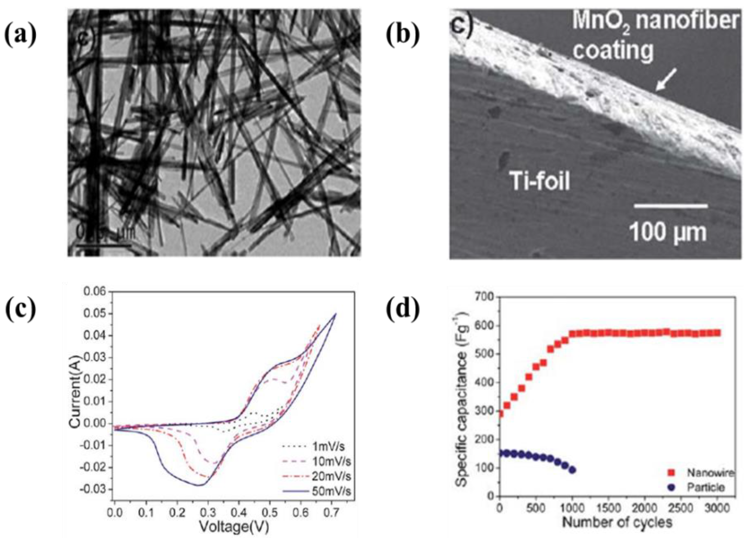
| 31 | MnO2 nanowire | Ti foil | IPA | 40 V | 1 h | A maximum capacitance of 1050 F·g−1 at a scan rate of 1 mV·s−1 and 750 F·g−1 of the specific capacitance at a current density of 1 mA·g−1 | [214] |
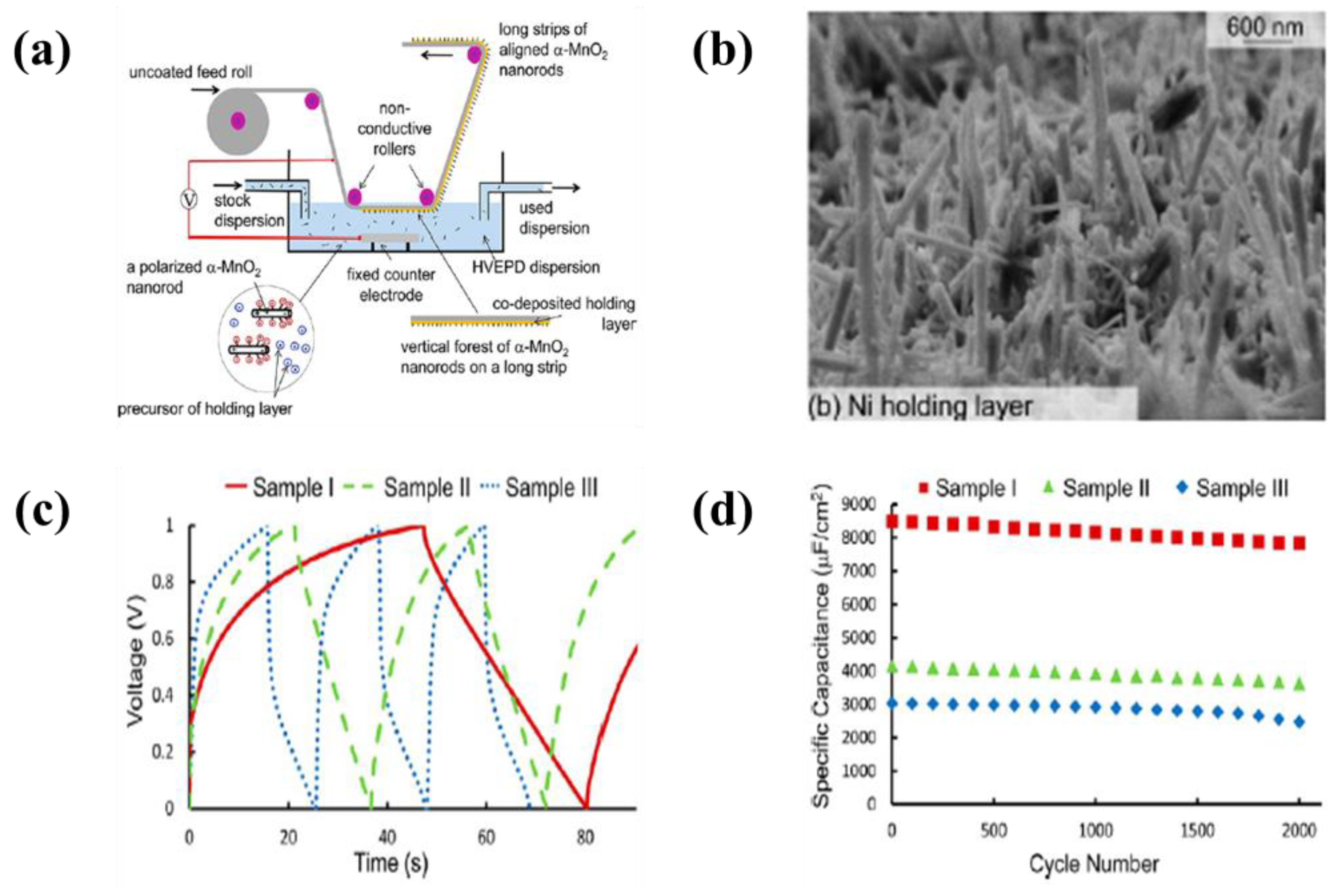
| 32 | α-MnO2 nanorod | SS foil | IPA, Mg(NO3)2∙6H2O, and NiCl2∙6H2O | 800 V | 30 s | A maximum capacitance of 8500 µF cm2 and 92% specific capacitance retention after 2000 cycles at a current density of 0.25 mA·cm−2 | [215] |
| 33 | MnO2 Nano/Micro hybrids | Ti foil | IPA | 40 V | 15 min | A specific capacitance of 1100 F·g−1 at a scan rate of 5 mV·s−1 and no reduction of the initial specific capacitance after 10000 cycles at a scan rate of 200 mV·s−1 | [216] |
| 34 | MnO2 | SS Graphite | Ethanol and PE | 10–100 V | 1–15 min | A maximum capacitance of 377 F·g−1 at a scan rate of 2 mV−1 (loading amount: 50 µg·cm−2) in 0.1 M Na2SO4 electrolyte | [352] |
| 35 | Aligned β-MnO2 nanorod | Stainless steel | Mg(NO3)2∙6H2O in isopropyl alcohol (IPA) | 150 V | 1 min | A maximum capacitance of 689 µF·cm−2 at a constant current density of 2 mA·cm−2 | [245] |
| 36 | NiO | SS foil | IPA and iodine, nickel nitrate or cobalt nitrate | 10 V | 30 s | A specific capacitance of 180 F·g−1 at a scan rate of 10 mV·s−1 and no change of specific capacitance retention after 4000 cycles at a constant current density of 8 A·g−1 in 0.5 M KOH electrolyte | [218] |
| 37 | NiO | SS foil | IPA, Iodine, and water | 10 V | 30 s | A specific capacitance of 112 F·g−1 at a scan rate of 10 mV·s−1 and 90% specific capacitance retention after 5000 cycles at a constant current of 4 A·g−1 in 0.5 M KOH electrolyte | [219] |
| 38 | NiO nanowires | Ti foil | IPA and nickel nitrate | 40 V | 60 min | A specific capacitance of 750 F·g−1 at a scan rate of 1 mV·s−1 and 12% capacitance fades after 1000 cycles in 0.1 M NaOH electrolyte | [220] |
| 39 | MnO2 nanoparticles-cationic celestine blue dye | Ni plaques | Ethanol | 20 V | 1–8 min | A specific capacitance of 0.34 F·cm−2 at a scan rate of 2 mV·s−1 and high capacitance retention of 88.5% in the scan rate of 2–100 mV·s−1 in 0.5 M Na2SO4 electrolyte | [241] |
| 40 | Polystyrene sphere/nickel hydroxide | SS foil | IPA | 60 V | 30 s | A specific capacitance of 800 F·g−1 at a discharge current density of 10 A·g−1 in 0.5 M KOH electrolyte | [211] |
| 41 | NiMoO4 | Ni foil | IPA | 40 V | 15 min | A specific capacitance of 972 F·g−1 at a scan rate of 1 mV·s−1 in 1 M NaOH electrolyte | [222] |
| 42 | Hybrid materials | SS foil | Water | 30 Hz 200 V | 30 s | A specific capacitance of 172 F·g−1 and good cyclability at 7 mA·cm−2 over 1100 cycles | [353] |
| 43 | PPY-MWCNTs | SS foil | Water | 1 mA·cm−2 | - | A specific capacitance of 224 F·g−1 at a scan rate of 2 mV·s−1 in 0.5 M Na2SO4 electrolyte (Pulsed electrophoretic deposition) | [223] |
| 44 | PBS-MnO2-MWCNTs | SS foil Pt coated wafer | Water | 1–10 V | 1–10 min | A specific capacitance of 250 and 90 F·g−1 at a scan rate of 2 and 100 mV·s−1 in 0.5 M Na2SO4 electrolyte, respectively | [224] |
| 45 | PPy nanofiber-MWCNTs-MG | SS | Water | 30 V | - | A maximum capacitance of 4.62 F·cm−2 at a scan rate of 2 mV·s−1 in 0.5 M Na2SO4 electrolyte (a material loading of 30 mg cm−2) | [225] |
| 46 | PPy coated MWCNTs | SS | Water and CHR-BS | 50–150 V | - | A maximum capacitance of 179 F·g−1 at a scan rate of 2 mV·s−1 in 0.5 M Na2SO4 electrolyte (a material loading of 10 mg cm−2) | [226] |
| 47 | Graphene-PPy | Ti plate | IPA and nickel nitrate | 20 V | 30 min | A maximum capacitance of 1510 F·g−1 and area capacitance of 151 F·cm−2 at a scan rate of 10 mV·s−1 in LiClO4 electrolyte, respectively | [227] |
| 48 | Graphene-PPy nanofibers | Ti plate | Water and safranin (SAF) | 30 V | 15 min | A specific capacitance of 354.2 and 225.6 F·g−1 at scan rates of 2 and 100 mV·s−1, respectively | [228] |
| 49 | Graphene-PANI nanofibers | Au | DMF and Mg(NO3)2∙6H2O | 80 V | 30 min | A specific capacitance of 667.5 µF·cm−1 at a constant current density of 15 µA·cm−1 in 0.5 M Na2SO4 electrolyte | [229] |
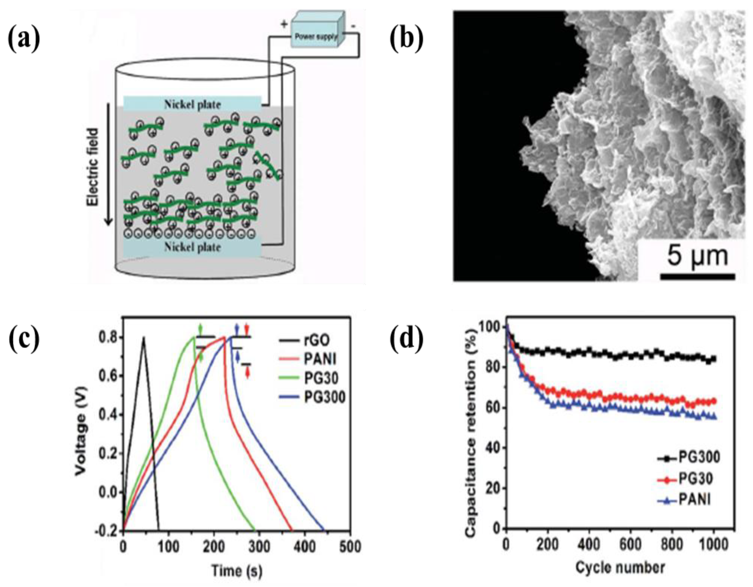
| 50 | Layred graphene-PANI | Ni plate | Water | -20 V | 20 min | A specific capacitance of 384 F·g−1 at a constant current density of 0.5 A·g−1 and 84% specific capacitance retention after 1000 cycles at a current density of 2 A·cm−2 in 1 M H2SO4 electrolyte | [230] |
| 51 | Mn oxide-MWCNTs | Graphite | Water | 100 V | 10–20 min | A specific capacitance of 260 F·g−1 at a constant current density of 25 mV·s−1 and 88% specific capacitance retention after 500 cycles at a current density of 25 mV·s−1 in 1 M Na2SO4 electrolyte | [231] |
| 52 | MnO2-MWCNTs | SS | Dopamine and water | 10–50 V | 1–10 min | A maximum capacitance of 650 F·g−1 at a scan rate of 2 mV·s−1 in 0.5 M Na2SO4 electrolyte | [232] |
| 53 | MnO2-MWCNTs | SS | Water and sodium alginate | 10–50 V | 1–10 min | A specific capacitance of 210 and 100 F·g−1 at scan rates of 2 and 100 mV·s−1 in 0.1 M Na2SO4 electrolyte, respectively | [233] |
| 54 | MnO2-MWCNTs | Ni foil | Ethanol and sulfuric acid | 50 V | 5 min | A specific capacitance of 158 F·g−1 at a constant current density of 2 A·g−1 in 1 M Na2SO4 electrolyte | [149] |
| 55 | MnO2-CNTs | SS | Water | 40 V | 4 min | A specific capacitance of 448 F·g−1 at a scan rate of 50 mV·s−1 and 869 F·g−1 at a constant current density of 2.5 A·g−1 in 0.65 M K2SO4 electrolyte | [234] |
| 56 | Mn-Mo mixed oxide-CNTs | ITO coated glass | IPA and Mg(NO3)2 | 80 V | 30 s | A maximum capacitance of 408 F·g−1 at a scan rate of 2 mV·s−1 and 86% specific capacitance retention after 1000 cycles in 0.5 M Na2SO4 electrolyte | [235] |
| 57 | MnO2 coated MWCNTs | Flexible graphite sheet | Water | 8 V | 5 min | A specific capacitance of 442.9 F·g−1 at a scan rate of 2 mV·s−1 and 98.9% specific capacitance retention after 1000 cycles in 0.5 M Na2SO4 electrolyte | [236] |
| 58 | MnO2 coated MWCNTs | SS | Ethanol containing CFB and CCA | 10–70 V | 1–15 min | A maximum capacitance of 290 F·g−1 at a scan rate of 2 mV·s−1 in 0.5 M Na2SO4 electrolyte (1 g·L−1 MnO2 suspension containing 0.13 g·L−1 MWCNTs and 0.2 g·L−1 CCA electrophoretically deposited art 40 V) | [237] |
| 59 | MWCNTs-α-MnOOH coaxial nanocable | Ni foil | Ethanol and water | 50 V | 150 s | A specific capacitance of 327 F·g−1 at a constant current density of 0.2 mA·cm−2 and retention of capacitance retention of 205 F·g−1 after 1200 cycles in 0.1 M Na2SO4 electrolyte | [238] |
| 60 | MnO2 nanowire- carbon nanobead | Ti foil | Isopropanol | 40 V | 15 min | A specific capacitance (10 wt.% carbon nanobead) of 625 F·g−1 at a scan rate of 100 mV·s−1 and high stability of the capacitance up to 10,000 cycles in 0.1 M KOH electrolyte | [239] |
| 61 | MnO2-MWCNTs | SS | Ethanol, PV, and PVB | 100 V | 2 min | A specific capacitance of 150 F·g−1 at a scan rate 2 mV·s−1 in 0.5 M Na2SO4 electrolyte | [240] |
| 62 | MnO2-Celestine blue | Ni Plaques | Ethanol, Celestine blue (CB) | 20 V | 1–8 min | A specific capacitance of 0.34 F·cm−2 at a scan rate of 2 mV·s−1 and 88.5% specific capacitance retention in the scan rate range of 2–100 mV·s−1 in 0.5 M Na2SO4 electrolyte | [241] |
| 63 | MnO2-MWCNTs | Graphite sheet | Water and sodium dodecylbenzene sulfonate | 8 V | 6 min | A specific capacitance of 540.7 F·g−1 at a scan rate of 2 mV·s−1 and 90% specific capacitance retention after 1000 cycles at a scan rate of 100 mV·s−1 in 0.5 M Na2SO4 electrolyte | [242] |
| 64 | NiO-vapor-grown carbon nanofiber (VGCF) | SS | VGCF: IPA and Ni(NO3)2 | 60 V | 30 s | A high capacitance retention of 91% after 6000 cycles in 0.5 M KOH electrolyte | [243] |
| NiO: IPA, iodine, water, and Ni(OH)2 | 10 V | 30 s | |||||
| 65 | Ni-decorated CNTs | SS | IPA | 60 V | 30 s | A specific capacitance of 117 and 100 F·g−1 at scan rates of 10 and 500 mV·s−1 in 0.5 M KOH electrolyte, respectively | [244] |
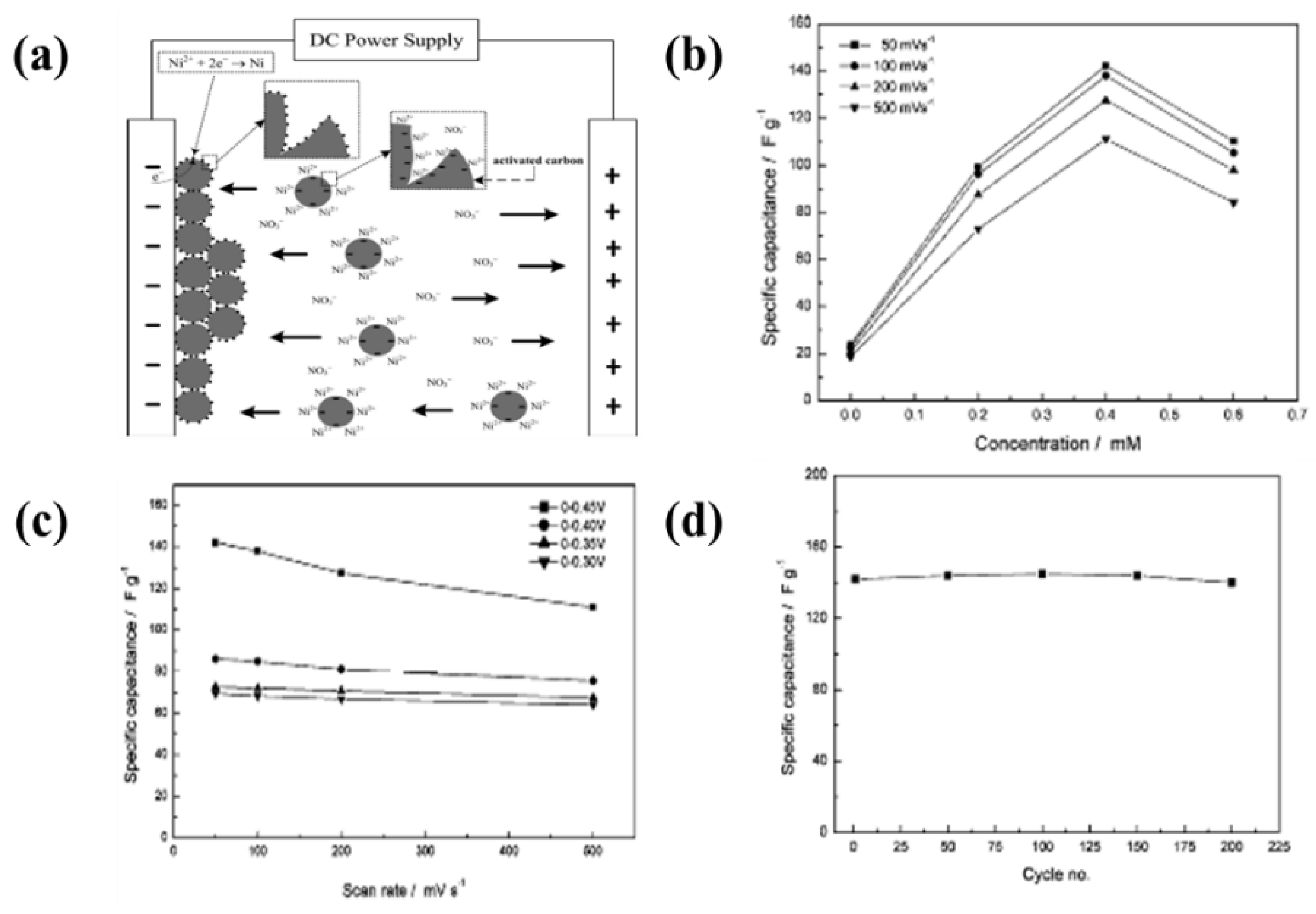
| 66 | Ni-decorated activated-carbon | SS | IPA and nickel nitrate | 151 V | - | A specific capacitance of 140 F·g−1 at a scan rate of 50 mV·s−1 and >95% specific capacitance retention after 200 cycles in 0.5 M KOH electrolyte | [245] |
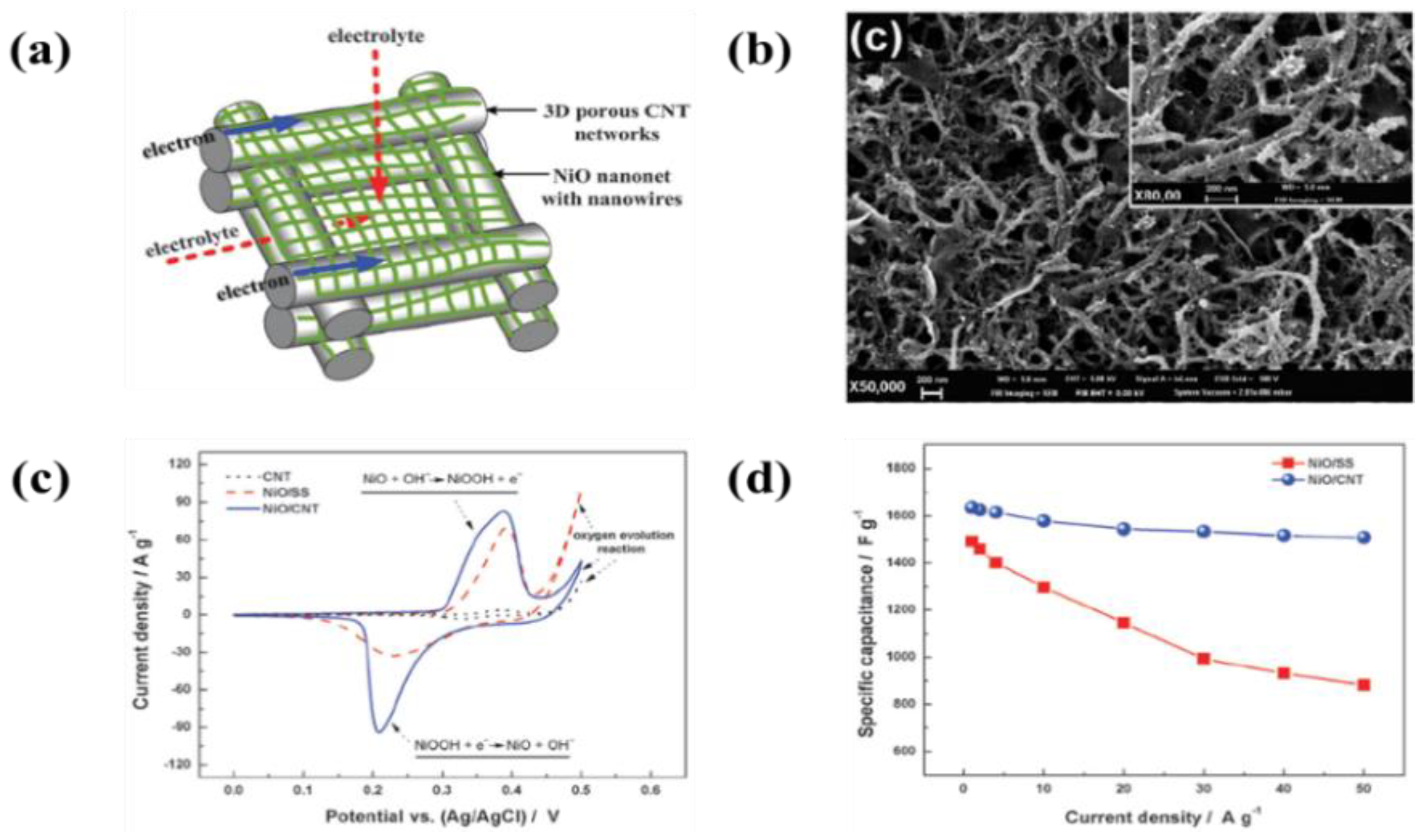
| 67 | NiO-MWCNTs | SS | IPA and Ni(NO3)2 | −60 V | - | A maximum capacitance of 1511 F·g−1 at a discharge current of 50 A·g−1in 1 M KOH electrolyte | [246] |
| 68 | Ni-BDC (1,4-bezenedicarboxylic acid) | SS | IPA | −60 V | 10 s | A specific capacitance of 886 F·g−1 at a constant current density of 1 A·g−1 and 87% capacitance retention after 1100 cycles at a constant current density of 20 A·g−1 in 1 M KOH electrolyte | [247] |
| 69 | Graphene nanosheet/porous NiO | Ni form | IPA and Mg(NO3)2∙6H2O | 100 V | 20 s | A specific capacitance of 400 and 324 F·g−1 at a constant current densities of 2 and 40 A·g−1, respectively in 1 M KOH electrolyte | [248] |
| 70 | Graphene nanosheets/MnO2 nanowires | SS | 1 step: IPA 2 step: Manganous acetate, sodium sulfate | 60 V 0.125 mA·cm−2 | - | A specific capacitance of 252 F·g−1 at a constant current density of 2 A·g−1 and 96% capacitance retention after 6000 cycles at a constant current density of 40 A·g−1 in 1 M Na2SO4 electrolyte | [249] |
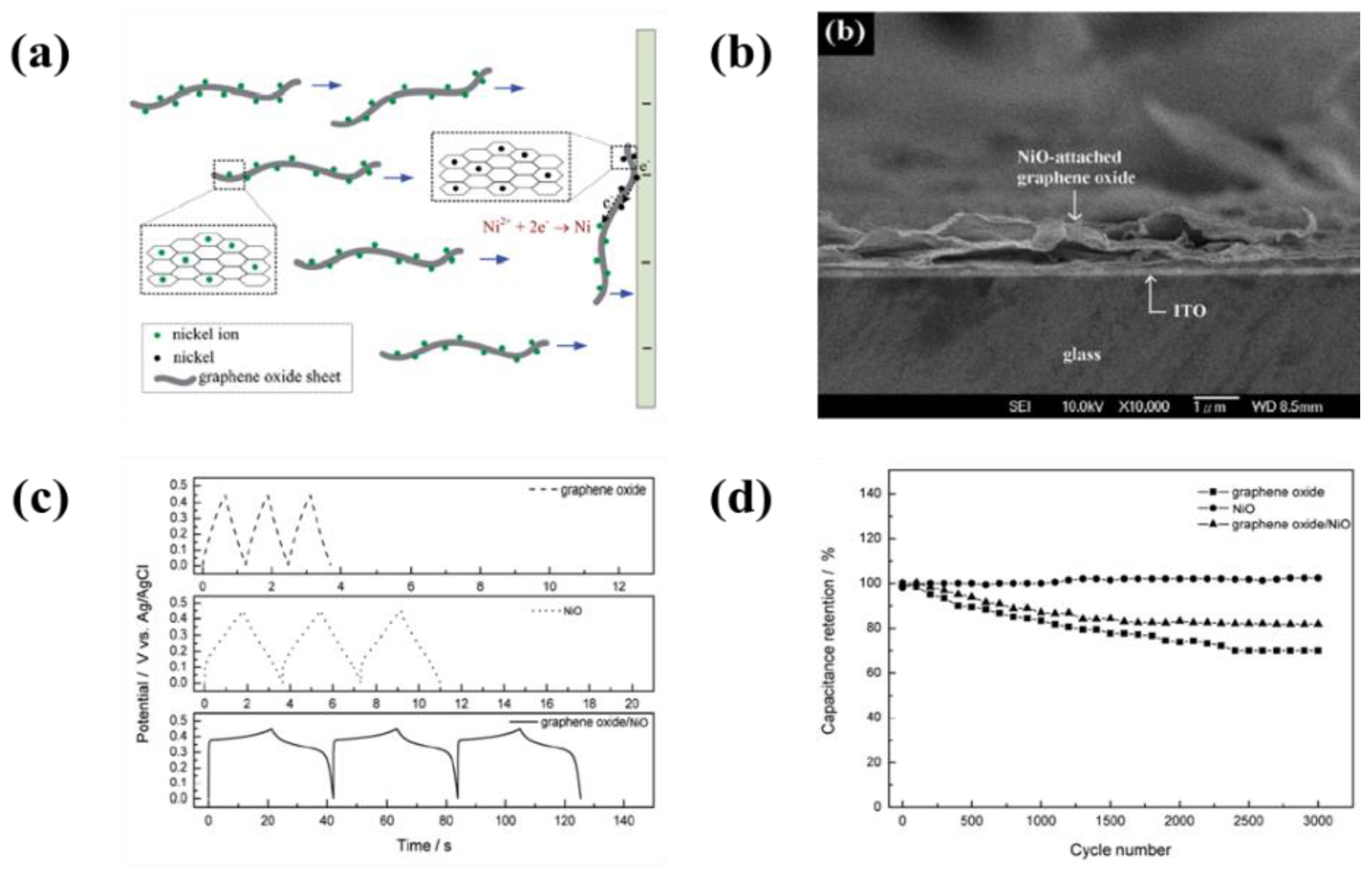
| 71 | NiO/graphene oxide nanosheets | SS | IPA and nickel nitrate | 60 V | - | A specific capacitance of 569 F·g−1 at a constant current density of 5 A·g−1 (NiO: 28 F·g−1, graphene oxide: 11 F·g−1) in 0.5 M KOH electrolyte | [253] |
| 72 | Multilayered graphene sheet/Au nanoparticles | ITO coated glass | DMF | 30 V | 8 min | A specific capacitance of 65 F·g−1 at a constant current density of 1 F·g−1in organic electrolyte | [254] |
| 73 | Graphene nanoribbons/MnO2 | SS | IPA Mn(NO3)2∙4H2O | 60 V −30 V | - | A specific capacitance of 266 F·g−1 at a constant current density of 1 A·g−1 and 98% capacitance retention after 3000 cycles at a constant current density of 10 A·g−1 in 1 M Na2SO4 electrolyte | [250] |
| 74 | Ni-CO hexacyanoferrate nanostructure/graphene | SS | Water | 5 V | 7 min | A maximum capacitance of 411 F·g−1 a constant current density of 0.2 A·g−1 and 83% capacitance retention after 800 cycles at a scan rate of 25 mV·s−1 in 1 M KNO3 electrolyte | [251] |
| 75 | MnO2 nanoparticles/graphene nanosheets | SS | Water | 4 V | 5 min | A specific capacitance of 392 F·g−1 at a constant current density of 1 A·g−1 and > 90% capacitance retention after 1200 cycles at a constant current density of 6 A·g−1 in 0.5 M Na2SO4 electrolyte | [252] |
| 76 | Graphene/MnO2/CNT | Ni plate | Hydrochloric acid and IPA | 50 V | 2 min | A maximum capacitance of 416 F·g−1 at a constant current density of 3 A·g−1 and 83.3% capacitance retention after 15,000 cycles at a constant current density of 3 A·g−1 in 0.1 M Na2SO4 electrolyte | [255] |
| 77 | Reduced graphene oxide/Ni(OH)2 | Ni form SS ITO coated glass | Water and Ni (NO3)2 | 2–10 V | 30–600 s | Maximum capacitances of 1404 and 1004 F·g−1 at constant current densities of 2 and 20 A·g−1, respectively in 6 M KOH electrolyte | [256] |
| 78 | PbO2-CNTs/graphene asymmetric electrode | Ti plate | Acetonitrile | 20 V | 60 min | A specific capacitance of 250 F·g−1 at a scan rate of 5 mV·s−1 and 87% capacitance retention after 3000 cycles at a scan rate of 100 mV·s−1 in 0.1 M KOH electrolyte | [260] |
| 79 | Graphene/carbon nanotube/MnO2 | Ni plate | Hydrochloric acid and IPA | 50 V | 2 min | A specific capacitance of 964 F·g−1 at a constant current density of 1 A·g−1 and 67% capacitance retention at constant current densities from 1 to 10 A·g−1 in 0.1 M Na2SO4 electrolyte | [354] |
| 80 | Graphene/Ni-Fe-HCF (hexacyanoferrate) | SS | Water | 5 V | 10 min | A specific capacitance of 67.77 mAh·g−1 at a constant current density of 0.5 Ag−1 and >95% capacitance retention at a scan rate of 0.02 V·s−1 in 0.5 KNO3 electrolyte | [355] |
| NiCl2∙6H2O, FeCl3∙6H2O, K3Fe(CN)6 | 0.35 V | 300 s | |||||
| 81 | RuO2-graphene-CNT | Carbon fiber cloth | CNT, CNS | 20 V | 5 min | A high specific capacitance up to 480.3 F·g−1 and remarkable cycling stability (89.4% capacitance retention after 10,000 cycles) | [356] |
| No. | Support Materials | Materials for EPD | Suspension Medium | EPD Conditions | Specification (An optimized Condition and a Power Density) | Ref. | |
|---|---|---|---|---|---|---|---|
| Voltage | Time | ||||||
| 1 | LSM | YSZ | Acetylacetone and I2 | 10 V | 3 min | A maximum power density of 1.5 W·cm−2 and open circuit voltage of 1.0 V, respectively | [263] |
| 2 | LSM | YSZ | Ketone and I2 | 10 V | 3 min | A maximum power density of 1.84 W·cm−2 and open circuit voltage of 1.03 V, respectively | [264] |
| 3 | LSM | YSZ | - | - | - | A maximum power density of 1.87 W·cm−2 and open circuit voltage of 1.03 V, respectively | [265] |
| 4 | LSM | LM/YSZ/NiO-YSZ multilayer | isopropanol | 20–600 V | 1–60 min | YSZ: at 40 V for 10 min in isopropanol NiO-YSZ: at 40 V for 10 min in isopropanol | [280] |
| 5 | Carbon interlayer coated LDM tube | YSZ | Glacial acetic acid | 50 V | 5 min | A density of 98.5% of YSZ with interlayer (94% of YSZ without interlayer) | [268] |
| 6 | LSM-YSZ | YSZ | Acetone including ethanol with amount of I2 | 5–40 V | 3–30 min | A high density of YSZ at 20 V for 8 min in suspension of I2 concentration of 0.6 g/L, YSZ concentration of 9.0 g/L, and a mixture of acetone/ethanol (volume ratio 3/1) | [273] |
| 7 | Stainless steel | 3YSZ, 6YSZ, and 8YSZ | n-propanol, methanol, ethanol, iso-propanol, n-butanol, ethylene glycol, acetone, and acetylacetone | 20–300 V | 1–30 min | A high dispersion of 8YSZ in n-propanol suspension and dense uniform coating at less than 100 V for 10 min | [277] |
| 8 | NiO-ScSZ | YSZ | n-propanol | 50 V | 1–30 min | A dense uniform coating at 50 V for 10 min and an OCV of 1.165 V at 928 K in anode-supported YSZ electrolyte deposited by EPD | [278] |
| 9 | NiO-YSZ | NiO-YSZ/YSZ bi-layers | Acetylacetone | 25–500 V | 1–3 min | A maximum power density of 434 mW·cm−2 and open circuit voltage of 0.99 V at 800 °C | [289] |
| 10 | NiO-YSZ | YSZ | Acetylacetone | 50–300 V | 1–5 min | A maximum power density of 611 mW·cm−2 and open circuit voltage of 0.88 V at 850 °C (at 50 V for 1 min) | [264] |
| 11 | NiO-YSZ | YSZ | I2 with isopropanol | 10 V | 60 min | A maximum power density of 440 mW·cm−2 and open circuit voltage of 1.0 V at 900 °C | [272] |
| 12 | Graphite | Ni-YSZ | Tetramethylammonium hydroxide (TMAH)adding 13polyacrylic acid based pol14yelectrolyte (PPA) 15and carboxymet16hylcellulose (CM17C) | 2 mA·cm−2 | 5–10 min | A higher electrophoretic mobility of powder in pH 9 and 10 adding 1.5 wt.% of PAA and 0.5 wt.% of CMC | [279] |
| 13 | NiO-YSZ | YSZ/SDC bi-layers | Ethanol | 600 V | - | A maximum power density of 0.6 W·cm−2 at 700 °C of bi-layered electrolyte consisting of 4 µm-thick YSZ and 1 µm-thick SEC films | [290] |
| 14 | Graphite coated NiO-YSZ | YSZ | Acetone | 400 V | - | A maximum power density of 2.01 W·cm−2 at 800 °C (YSZ of 5 µm-thick) | [269] |
| 15 | NiO-YSZ | YSZ | Acetylacetone | 25–100 V | 1–3 min | A maximum power density of 263.8 mW·cm−2 and open circuit voltage of 0.97 V at 650 °C (100 V for 3 min) | [267] |
| 16 | NiO-YSZ | YSZ | Water adding ammonium polyacrylate (PPA-NH4) | 2.2 mA·cm−2 | 30 and 75 s | A dense and uniform YSZ electrolyte film of 6 µm-thick and increase of deposition rate with increasing current density and with decreasing PAA-NH4 concentration | [281] |
| 17 | Fecralloy | YSZ | Acetylacetone adding I2 | 15–480 V 0–250 V | 1–20 min | A reduction of deposit porosity of electrolyte after a first step of a 240 s EPD in an electric field of 60 V and then 240 s EPD in an electric field of 240 V as a second step | [270] |
| 18 | LSM/YSZ | YSZ | Mixture of acetone/ethanol adding I2 | 10–40 V | 4–8 min | An uniform film without cracks in suspension of acetone/ethanol (rate: 50/50 mL) at 30 V for 6 min | [274] |
| 19 | NiO-YSZ | YSZ | acetone/ethanol (50:50) | 20 V | 1–4 min | A dense thick film without crack at 20 V for 1 min leaded to a better result in EIS analysis | [275] |
| 20 | NiO-YSZ | YSZ | Ethanol adding polyethylene glycol (PEG) | 30 V | 1.5 min | A maximum power density of 850 mW·cm−2 at 850 °C (YSZ of 10 µm-thick) | [276] |
| 21 | NiO-YSZ | YSZ | Acetylacetone | 50–300 V | 1–5 min | A maximum power density of 624 mW·cm−2 and open circuit voltage of 1.03 V at 800 °C (EPD conditions: at 100 V for 3 min) | [271] |
| 22 | Cu wire | NiO-YSZ, YSZ, and LSM | Water adding ammonium polyacrylate (PPA-NH4) | 1, 5, and 10 mA·cm−2 | - | A maximum power density of 3.5 mW·cm−2 at 800 °C (YSZ of 6 µm-thick) | [295] |
| 23 | Carbon coated YSZ | LSM-YSZ/LSM bi-layers | Acetylacetone adding I2 | 15 V | - | A minimal polarization resistance of LSM/YSZ (10:4 (v:v)) bi-layered film at 600 °C (4 µm-thick) | [292] |
| 24 | Cu wire | NiO-YSZ, YSZ, and LSM | Water adding ammonium polyacrylate (PPA-NH4) | 2, 5, and 10 mA·cm−2 | - | A maximum power density of 363.8 mW·cm−2 at 800 °C (YSZ of 35 µm-thick) | [296] |
| 25 | Cu wire | NiO-YSZ, YSZ, and LSM | Water adding ammonium polyacrylate (PPA-NH4) | 100 mA·cm−2 | - | A maximum power density of 363.8 mW·cm−2 at 800 °C (the anode with 70 wt.% NiO) | [297] |
| 26 | Stainless steel | NiO-YSZ | Ethanol, acetone, methanol, isopropanol, acetyl acetone, and n-butanol adding I2 | 50–300 V | 30–420 s | A high deposition rate of 60NiO-40YSZ (wt.%) in isopropanol-suspension adding 0.5 mM I2 (EPD conditions: at 200 V for 3 min) | [357] |
| 27 | NiO-YSZ | YSZ | Acetylacetone and acetone with ethanol | 110 V | 2.5 min | A maximum power density of 200 mW·cm−2 at 800 °C (YSZ of 40 µm-thick) | [298] |
| 28 | Ni fole | LSGM, LSCF, and YSG | Ethanol adding phosphate ester and polyvinyl butyral | 0.05–1 mA·cm−2 | 1–10 min | A good dispersion and charging of ceramic particles in phosphate ester as well as improvement of adhesion of the deposits without cracking by using polyvinyl bytyral in ethanol-based suspension | [282] |
| 29 | Ni fole | LSGM, CGO, and YSG | Ethanol and isopropanol adding phosphate ester and polyvinyl butyral | 50–200 V | 1–6 min | A high deposition rate of LSGM and YSG in ethanol and CGO in isopropanol (adding polyvinyl butyral) | [283] |
| 30 | Graphite | LSGM | Acetylacetone adding I2 | 20 mA·cm−2 | 50–200 s | A maximum power density of 0.5 W·cm−2 at 700 °C (LSGM of 40 µm-thick) | [284] |
| 31 | LDC | LSGM | Acetone and water adding I2 | 20–80 V | - | A good degree of packing of LSGM particles in suspension (I2: 0.1 g·L−1, H2O: 45 mL·L−1) | [286] |
| 32 | LDC | LSGM | Acetone and water adding I2 | - | - | A maximum power density of 780 mW·cm−2 at 700 °C (LSGM of 30 µm-thick) | [287] |
| 33 | LDC | LSGCM | Acetone and water adding I2 | 80 V | 2 min | A good degree of packing of LSGM particles in suspension (I2: 0.1 g·L−1 in acetone, H2O: 60 mL·L−1, powder: 0.9 g·L−1) | [288] |
| 34 | YSZ-BCYO | BCY10 | Acetylacetone adding I2 | 40 V | 5 min | A maximum power density of 174 mW·cm−2 at 650 °C (BCYO of 12 µm-thick) | [293] |
| 35 | YSZ-BCYO | BCY10 | Acetylacetone adding I2 | 30–60 V | 1 min | A maximum power density of 296 mW·cm−2 at 700 °C (EPD at 60 V for 1 min) | [294] |
| 36 | NiO-SSZ | SSZ | Acetylacetone adding I2 | 10–50 V | 5–50 min | A maximum power density of 1.8, 1.2, 0.4, and 0.1 W·cm−2 at 900, 800, 700, and 600 °C, respectively (BCYO of 12 µm-thick) | [358] |
| 37 | NiO-SDC | SDC | Mixture of acetone and ethanol (3:1/v:v) adding I2 | 60 V | 1–3 min | A maximum power density of 155 mW·cm−2 and open circuit voltage of 0.92 V at 600 °C (EPD conditions: at 60 V for 1 min) | [292] |
| 38 | NiO-LCN | LCN | Water and acetylacetone adding I2 | 25 V | 2 min | An electrolyte specific resistance of 1.3 Ω·cm2 at 800 °C (LNC of 10 µm-thick) | [359] |
| 39 | NiO-LCN | NiO-LCN | Water and acetylacetone adding I2 | 25 V | 3 min | An electrolyte specific resistance of 0.16 Ω·cm2 at 800 °C | [290] |
| 40 | CGO | LSCF | Acetylacetone, ethyl alcohol, and acetone adding pol(vinlbutyral-co-vinyl alcohol-co-vinyl acetate), and phosphate ester, starch | 10–40 V | 1–5 min | A high uniform LSCF film at 20 V for 2 min in suspension containing acetylacetone, I2, and starch | [285] |
| 41 | T441 stainless steel | (Mn, Co)3O4 | Ethanol | 200–500 V | 1 min | An ASR of 17.2 mΩ·cm2 in film deposited with 400 V for 1 min | [299] |
| 42 | Crofer22APU | (Mn, Co)3O4 | Mixture of ethanol and water (volume ratio: 60/40) | 50 V | 20 s | An ASR of 20 mΩ·cm2 at 800 °C for 1000 h under air | [300] |
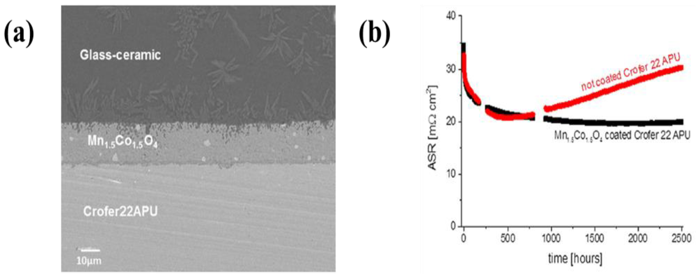
| 43 | Crofer22APU | (Mn, Co)3O4 | Acetone | 20 V | 1 min | An ASR of 17 mΩ·cm2 at 800 °C for 50 h under air | [301] |
| 44 | PPY-coated NiO-YSZ | YSZ | Isopropanol medium using iodine, acetylacetone, and water | 15–40 V | 1–4 min | A maximum power density of 0.91 W·cm−2 at 0.7 V (EPD conditions: at 15 V for 1 min) | [55] |
| No. | Support Materials | Materials for EPD | Suspension Medium | EPD Conditions | Specification (an Optimized Condition and a Power Density) | Ref. | |
|---|---|---|---|---|---|---|---|
| Voltage | Time | ||||||
| 1 | Silver mesh | AB-6 | Water, Triton X-100, PTEF | 30 V | 45 s | A generated 0.77 V at 0.3 A·cm−2 in gas diffusion electrode fabricated by EPD | [308] |
| AB-6, Ketjenblack | Water, Triton X-100, PTEF | 30 V | 15 s | ||||
| 1 | Nafion 117 | Pt/C | Ethanol, Nafion inomer | 1000 V | 5–15 min | A current density of 270 mA·cm−2 at a cell potential of 0.5 V (EPD time: 10 min) | [309] |
| 3 | Carbon fiber paper | SWCNTs | Tetraoctylammonium bromide | 80 V | 2–5 min | A ECSA of 30.8 m2·g−1 and a maximum power density of 240 mW·cm2 at 60 °C | [310] |
| Pt/C | Tetrahydrofuran and Nafion solution | - | - | ||||
| 4 | Carbon textile | XC-72 carbon | Ethanol and Nafion inomer | 250 V | 30 s | A current density of 105 mA·cm−2 at low output voltage region at 0.3–0.5 V (a catalyst loading of 0.16 Pt-mg·cm2) | [311] |
| Pt/C | Ethanol and Nafion solution | - | - | ||||
| 2 | Carbon paper | Pt-SiO2 | Tetrahydrofuran and Nafion inomer | 75 | - | A highest power density at 2:1 ratio of Pt-SiO2 (about 225 mW·cm−2 at 40 °C and a catalyst loading of 0.2 mg·cm2 including the mass of silica | [312] |
| 3 | Carbon paper | PtRu/MWCNTs | HClO4 and Nafion inomer | 5 V | 30 min | A maximum power density of 27 mW·cm−2 at 60 °C (a catalyst loading of 0.16 Pt-mg·cm2) | [313] |
| 4 | Nafion-carbon layer coated carbon paper | Pt nanoparticles | Pt colloids (pH 2–5) | Duty cycle: 25% | 10 min | A maximum mass-specific current density of 440.6 mA·mgpt−1 (a catalyst loading of 0.16 Pt-mg·cm2) | [317] |
| 5 | Nafion-carbon layer coated carbon paper | Pt nanoparticles | Pt colloids | 30 mA·cm−2 Duty cycle: 25% | 10 min | A ECSA of 37.8 m2·g−1 and a current density of 517 mA·cm−2 at a cell potential of 0.6 V at 70 °C (a catalyst loading of 0.198 Pt-mg·cm2) | [318] |
| 6 | Carbon paper | Pt/C | Isopropanol and Nafion inomer | 100 V | - | A maximum power density of 180 mW·cm−2 at 160 °C (in suspension including 30 wt.% Nafion solution) | [314] |
| 7 | Au coated PDMS | PtRu/C | Water and Nafion inomer | 5 V | 10 min | A maximum power density of 6.28 mW·cm−2 and OCV of 0.87 V at 25 °C | [315] |
| 8 | Carbon paper | Pt/C | Isopropyl alcohol and Nafion inomer or PTEF | 100 V | A maximum power density of 187 mW·cm−2 at 160 °C (in suspension including 40 wt.% PTEF solution) | [316] | |
| 9 | Carbon nanofiber coated carbon paper | Pt nanoparticles | Pt colloids | - | - | A ECSA of 36.37 m2·g−1 and specific current density of 6.33 × 10⁻³ A·cm−1 for ORR | [319] |
| 13 | Optically transparent electrode | C60 | Acetonitrile and toluene (3:1 (v/v)) | 100 V | - | A maximum current density of 3.6 mA·cm−2 in C/Pt ratio of 1:2 for methanol oxidation reaction | [324] |
| Pt nanoparticles | H2PtCl6 | −350 mV vs. SEC | - | ||||
| 14 | Optically transparent electrode | SWCNTs | Tetraoctylammonium bromide and tetrahydrofuran | 500 V | 1 min | A maximum current density of 60 mA·cm−2 for methanol oxidation reaction and an exchange current density of 6.3 × 10⁻⁴ A·cm−2 for oxygen reduction reaction | [325] |
| Pt nanoparticles | H2PtCl6 | −350 mV vs. SEC | - | ||||
| 15 | Glassy carbon electrode | Carbon nanofiber | Ethanol and Mg(NO3)∙6H2O | 30 V | 10 min | A maximum current density of 80 mA·cm−2 for ethanol oxidation reaction and a current density of 73.2 mA·cm−2 after CV test during 300 cycles | [320] |
| Pd nanoparticles | PdCl2 (pH 1.5) | 100 mA·cm−2 | - | ||||
| 10 | Carbon paper | GO-Pt | Water, tetrahydrofuran, and Nafion inomer | 75 V | - | A maximum power density of about 160 mW·cm−2 at 60 °C (a catalyst loading of 0.2 mg·cm2) | [321] |
| 17 | ITO coated glass | GO | Water | 150 V | 40 s | A maximum current density of 7.41 mA·cm−2 for methanol oxidation reaction and higher current density compared to Pt/glass carbon (4.31 mA·cm−2) | [322] |
| Pt nanoparticles | H2PtCl6 and H2SO4 | −0.25 V | 30 min | ||||
| 18 | ITO coated glass | Reduced GO | Water | 4 V | 30 s | A ECSA of 1.54 cm2·g−1 in electrode electrophoretically deposited at 10 min | [323] |
| Pt nanoparticles | Pt colloids | 5 V | 3–10 min | ||||
| 11 | ITO coated glass | Reduced GO/Pt nanoparticles | DMF | 5 V | 10–60 s | A ECSA of 2.04 cm2·g−1 in electrode electrophoretically deposited at 60 s | |
| 12 | Ni plate | ZnCo2O4 | Ethanol, polyvinylbytyral, and phosphate ester | 10–30 V | 1–5 min | A maximum current density of 289.6 mA·cm−2 at given potential of 0.7 V in electrode deposited at 20 V for 5 min in 1 M KOH electrolyte | [329] |
| 13 | Carbon glass electrode | Co nanoparticles | Hexane | 300 V | 30 s | A maximum diffusion limited current of −62.6 Agcatalyst in electrode deposited by EPD (−49.3 Agcatalyst in electrode deposited by dropcast) | [330] |
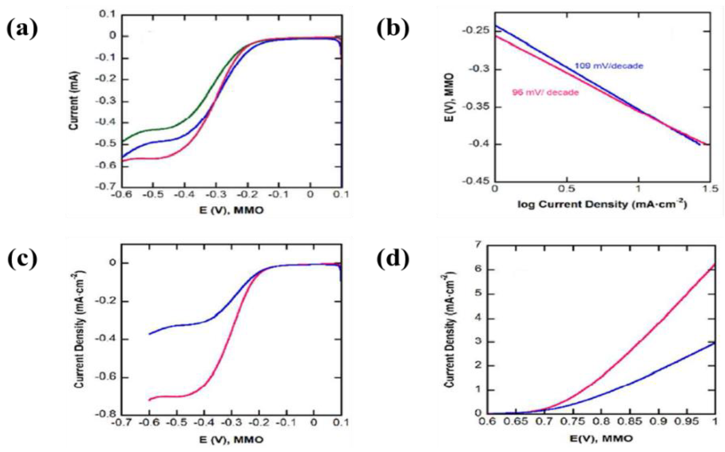
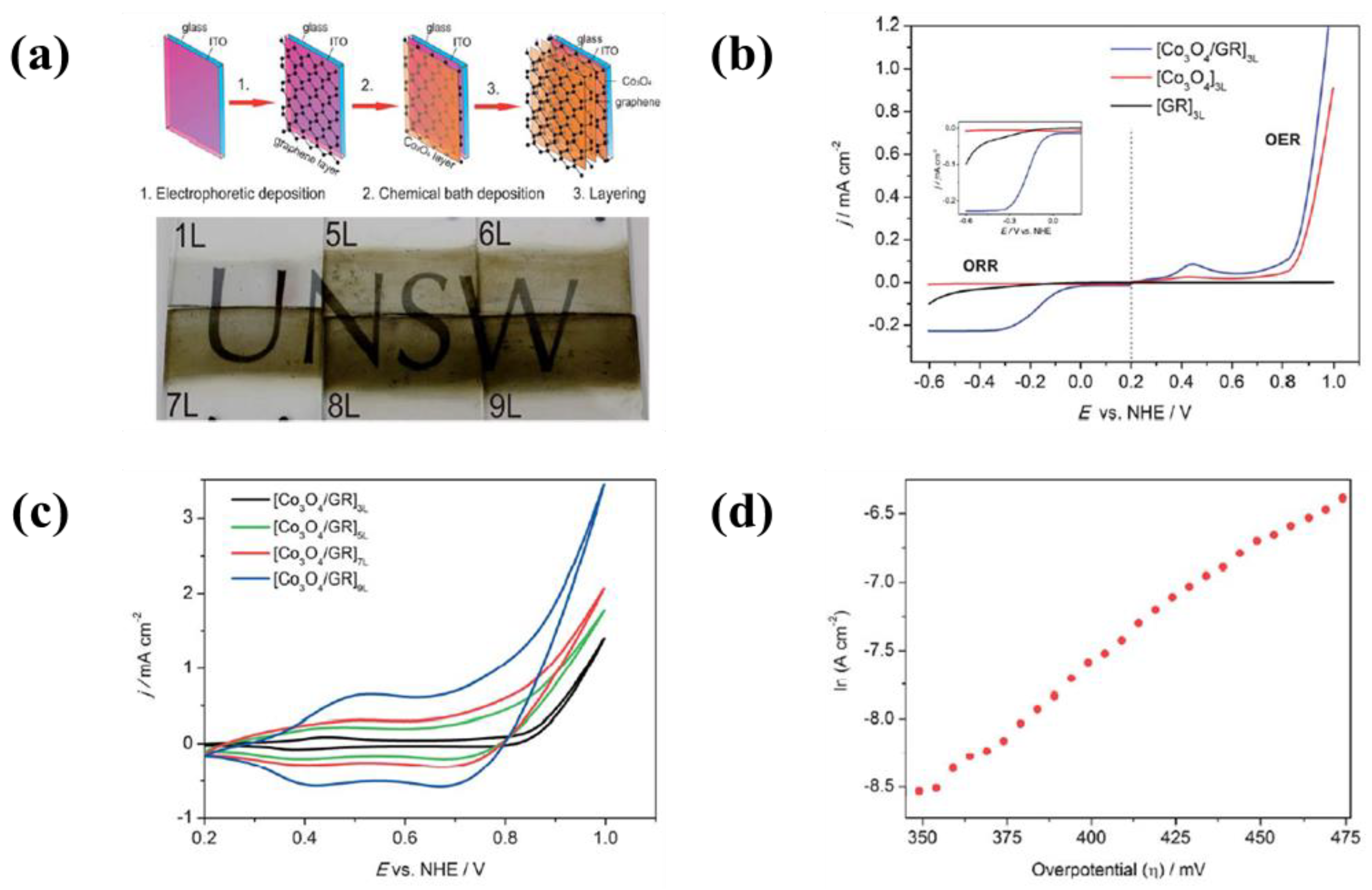
| 22 | ITO coated glass | Reduced graphene oxide | Water and NH4OH (pH: 10.0–10.5) | 1.25 mA | 75 s | A current density of 1.30 mA·cm−2 at an applied potential of 1 V for OER and a current density of 0.2 mA·cm−2 at an applied potential of −0.3 V for ORR | [331] |
| Co3O4 nanoparticles | 0.05 M [Co(HH3)6]2+ | - | - | ||||
| 14 | ITO coated glass | NiO nanoparticles | Isopropyl alcohol and magnesium nitrate hexahydrate | - | - | A low onset voltage of −0.2 V (vs. Ag/AgCl) accompanied by an anodic peak at around 0.3 V (vs. Ag/AgCl), | [29] |
References
- Dunn, B.; Kamath, H.; Tarascon, J.-M. Electrical Energy Storage for the Grid: A Battery of Choices. Science 2011, 334, 928–935. [Google Scholar] [CrossRef] [PubMed]
- Armand, M.; Tarascon, J.-M. Building better batteries. Nature 2008, 451, 652–657. [Google Scholar] [CrossRef] [PubMed]
- Bruce, P.G.; Freunberger, S.A.; Hardwick, L.J.; Tarascon, J.-M. Li-O2 and Li-S batteries with high energy storage. Nat. Mater. 2012, 11, 19–29. [Google Scholar] [CrossRef] [PubMed]
- Larcher, D.; Tarascon, J.-M. Towards greener and more sustainable batteries for electrical energy storage. Nat. Chem. 2015, 7, 19–29. [Google Scholar] [CrossRef] [PubMed]
- Bruce, P.G.; Scrosati, B.; Tarascon, J.-M. Nanomaterials for Rechargeable Lithium Batteries. Angew. Chem. Int. Ed. 2008, 47, 2930–2946. [Google Scholar] [CrossRef] [PubMed]
- Tarascon, J.M.; Armand, M. Issues and challenges facing rechargeable lithium batteries. Nature 2011, 414, 359–367. [Google Scholar] [CrossRef] [PubMed]
- Goodenough, J.B.; Kim, Y.S. Challenges for Rechargeable Li Batteries. Chem. Mater. 2010, 22, 587–603. [Google Scholar] [CrossRef]
- Scrosati, B.; Hassoun, J.; Sun, Y.-K. Lithium-ion batteries. A look into the future. Energy Environ. Sci. 2011, 4, 3287–3295. [Google Scholar] [CrossRef]
- Etacheri, V.; Marom, R.; Elazari, R.; Salitra, G.; Aurbach, D. Challenges in the development of advanced Li-ion batteries: A review. Energy Environ. Sci. 2011, 4, 3243–3262. [Google Scholar] [CrossRef]
- Wang, H.; Dai, H. Strongly coupled inorganic-nano-carbon hybrid materials for energy storage. Chem. Soc. Rev. 2013, 42, 3088–3113. [Google Scholar] [CrossRef] [PubMed]
- Simon, P.; Gogotsi, Y. Materials for electrochemical capacitors. Nat. Mater. 2008, 7, 845–854. [Google Scholar] [CrossRef] [PubMed]
- Wang, G.; Zhang, L.; Zhang, J. A review of electrode materials for electrochemical supercapacitors. Chem. Soc. Rev. 2012, 41, 797–828. [Google Scholar] [CrossRef] [PubMed]
- Cao, X.; Yin, Z.; Zhang, H. Three-dimensional graphene materials: Preparation, structures and application in supercapacitors. Energy Environ. Sci. 2014, 7, 1850–1865. [Google Scholar] [CrossRef]
- Yu, Z.; Tetard, L.; Zhai, L.; Thomas, J. Supercapacitor electrode materials: Nanostructures from 0 to 3 dimensions. Energy Environ. Sci. 2015, 8, 702–730. [Google Scholar] [CrossRef]
- Kou, R.; Shao, Y.; Mei, D.; Nie, Z.; Wang, D.; Wang, C.; Viswanathan, V.V.; Park, S.H.; Aksay, I.A.; Lin, Y.; et al. Stabilization of Electrocatalytic Metal Nanoparticles at Metal–Metal Oxide–Graphene Triple Junction Points. J. Am. Chem. Soc. 2011, 133, 2541–2547. [Google Scholar] [CrossRef] [PubMed]
- Lin, J.; Peng, Z.; Wang, G.; Zakhidov, D.; Larios, E.; Yacaman, M.J.; Tour, J.M. Enhanced Electrocatalysis for Hydrogen Evolution Reactions from WS2 Nanoribbons. Adv. Energy Mater. 2014, 4, 1301875. [Google Scholar] [CrossRef]
- Mengmeng, Z.; Rong, L.; Xiaoxuan, C.; Chao, X.; Xinglong, G. Hybrid of porous cobalt oxide nanospheres and nitrogen-doped graphene for applications in lithium-ion batteries and oxygen reduction reaction. J. Power Sources 2015, 290, 25–34. [Google Scholar]
- Gnana kumar, G.; Christy, M.; Jang, H.S.; Nahm, K.S. Cobaltite oxide nanosheets anchored graphene nanocomposite as an efficient oxygen reduction reaction (ORR) catalyst for the application of lithium-air batteries. J. Power Sources 2015, 288, 451–460. [Google Scholar] [CrossRef]
- Liu, N.; Lu, Z.; Zhao, J.; McDowell, M.T.; Lee, H.W.; Zhao, W.; Cui, Y. A pomegranate-inspired nanoscale design for large-volume-change lithium battery anodes. Nat. Nanotechnol. 2014, 9, 187–192. [Google Scholar] [CrossRef] [PubMed]
- Liqiang, M.; Xiaocong, T.; Xu, X.; Liang, C.; Lin, X. Nanowire Electrodes for Electrochemical Energy Storage Devices. Chem. Rev. 2014, 114, 11828–11862. [Google Scholar]
- Islam, M.S.; Fisher, C.A.J. Lithium and sodium battery cathode materials: Computational insights into voltage, diffusion and nanostructural properties. Chem. Soc. Rev. 2014, 43, 185–204. [Google Scholar] [CrossRef] [PubMed]
- Roberts, A.D.; Li, X.; Zhang, H. Porous carbon spheres and monoliths: Morphology control, pore size tuning and their applications as Li-ion battery anode materials. Chem. Soc. Rev. 2014, 43, 4341–4356. [Google Scholar] [CrossRef] [PubMed]
- Ding, D.; Li, X.; Lai, S.Y.; Gerdesb, K.; Liu, M. Enhancing SOFC cathode performance by surface modification through infiltration. Energy Environ. Sci. 2014, 7, 552–575. [Google Scholar] [CrossRef]
- Ding, X.; Yin, S.; An, K.; Luo, L.; Shi, N.; Qiang, Y.; Pasupathi, S.; Pollet, B.G.; Shen, P.K. FeN stabilized FeN@Pt core-shell nanostructures for oxygen reduction reaction. J. Mater. Chem. A 2015, 3, 4462–4469. [Google Scholar] [CrossRef]
- Wang, Z.; Shemilt, J.; Xiao, P. Fabrication of ceramic composite coatings using electrophoretic deposition, reaction bonding and low temperature sintering. J. Eur. Ceram. Soc. 2002, 22, 183–189. [Google Scholar] [CrossRef]
- Yang, Y.; Li, J.; Chen, D.; Zhao, J. A Facile Electrophoretic Deposition Route to the Fe3O4/CNTs/rGO Composite Electrode as a Binder-Free Anode for Lithium Ion Battery. ACS Appl. Mater. Interfaces 2016, 8, 26730–26739. [Google Scholar] [CrossRef] [PubMed]
- Zhitomirsky, I. Electrophoretic hydroxyapatite coatings and fibers. Mater. Lett. 2000, 42, 262–271. [Google Scholar] [CrossRef]
- Ishihara, T.; Sato, K.; Takita, Y. Electrophoretic Deposition of Y2O3-Stabilized ZrO2 Electrolyte Films in Solid Oxide Fuel Cells. J. Am. Ceram. Soc. 1996, 79, 913–919. [Google Scholar] [CrossRef]
- Daryakenari, A.A.; Hosseini, D.; Ho, Y.L.; Saito, T.; Apostoluk, A.; Muller, C.R.; Delaunay, J.J. Single-Step Electrophoretic Deposition of Non-noble Metal Catalyst Layer with Low Onset Voltage for Ethanol Electro-oxidation. ACS Appl. Mater. Interfaces 2016, 8, 15975–15984. [Google Scholar] [CrossRef] [PubMed]
- Kanamura, K.; Goto, A.; Rho, Y.O.; Umegaki, T. Electrophoretic fabrication of LiCoO2 positive electrodes for rechargeable lithium batteries. J. Power Sources 2001, 97–98, 294–297. [Google Scholar] [CrossRef]
- Xia, X.; Tu, J.; Mai, Y.; Chen, R.; Wang, X.; Gu, C.; Zhao, X. Graphene Sheet/Porous NiO Hybrid Film for Supercapacitor Applications. Chem. Eur. J. 2011, 17, 10898–10905. [Google Scholar] [CrossRef] [PubMed]
- Wu, M.S.; Lin, Y.P.; Lin, C.H.; Lee, J.T. Formation of nano-scaled crevices and spacers in NiO-attached graphene oxide nanosheets for supercapacitors. J. Mater. Chem. 2012, 22, 2442–2448. [Google Scholar] [CrossRef]
- Sarkar, P.; Nicholson, P.S. Electrophoretic Deposition (EPD): Mechanisms, Kinetics, and Application to Ceramics. J. Am. Ceram. Soc. 1996, 79, 1987–2002. [Google Scholar] [CrossRef]
- Besra, L.; Liu, M. A review on fundamentals and applications of electrophoretic deposition (EPD). Prog. Mater. Sci. 2007, 51, 1–61. [Google Scholar] [CrossRef]
- Gani, M.S. Electrophoretic Deposition—A Review. Ind. Ceram. 1994, 14, 163–174. [Google Scholar]
- Corni, I.; Ryan, M.P.; Bccaccini, A.R. Electrophoretic deposition: From traditional ceramics to nanotechnology. J. Eur. Ceram. Soc. 2008, 28, 1353–1367. [Google Scholar] [CrossRef]
- Boccaccini, A.R.; Roether, J.A.; Thomas, B.J.C.; Shaffer, M.S.P.; Chavez, E.; Stoll, E. Electrophoretic deposition of carbon nanotubes. Carbon 2006, 44, 3149–3160. [Google Scholar] [CrossRef]
- An, Q.; Rider, A.N.; Thostenson, E.T. Electrophoretic deposition of carbon nanotubes onto carbon-fiber fabric for production of carbon/epoxy composites with improved mechanical properties. Carbon 2012, 50, 4130–4143. [Google Scholar] [CrossRef]
- Kanamura, K.; Hamagami, J. Innovation of novel functional material processing technique by using electrophoretic deposition process. Solid State Ion. 2004, 172, 303–308. [Google Scholar] [CrossRef]
- Zhitomirsky, I. Cathodic electrodeposition of ceramic and organoceramic materials. Fundamental aspects. Adv. Colloid Interface Sci. 2002, 97, 279–317. [Google Scholar] [CrossRef]
- Van der Biest, O.O.; Van der perre, L.J. Electrophoretic Deposition of Materials. Annu. Rev. Mater. Sci. 1999, 29, 327–352. [Google Scholar] [CrossRef]
- Fukada, Y.; Nagarajan, N.; Mekky, W.; Bao, Y.; Kim, H.S.; Nicholson, P. Electrophoretic deposition—Mechanisms, myths and materials. J. Mater. Sci. 2004, 39, 787–801. [Google Scholar] [CrossRef]
- Hamaker, H.C. Formation of a deposit by electrophoresis. Trans. Faraday Soc. 1940, 35, 279–287. [Google Scholar] [CrossRef]
- Hamaker, H.C.; Verwey, E.J.W. Part II.—(C) Colloid stability. The role of the forces between the particles in electrodeposition and other phenomena. Trans. Faraday Soc. 1940, 36, 180–185. [Google Scholar] [CrossRef]
- Hanaor, D.; Michelazzi, M.; Leonelli, C.; Sorrell, C.C. The effects of carboxylic acids on the aqueous dispersion and electrophoretic deposition of ZrO2. J. Eur. Ceram. Soc. 2012, 32, 235–244. [Google Scholar] [CrossRef]
- Grillon, F.; Fayeulle, D.; Jeandin, M. Quantitative image analysis of electrophoretic coatings. J. Mater. Sci. Lett. 1992, 11, 272–275. [Google Scholar] [CrossRef]
- Brown, D.R.; Salt, F.W. The mechanism of electrophoretic deposition. J. Appl. Chem. 1965, 15, 40–48. [Google Scholar] [CrossRef]
- Koelmans, H. Suspensions in non-aqueous media. Philips Res. Rep. 1955, 10, 161–193. [Google Scholar]
- Cannio, M.; Novak, S.; Besra, L.; Boccaccini, A.R. Electrophoretic Deposition. In Ceramics and Composites Processing Methods; Bansal, N.P., Boccaccini, A.R., Eds.; Bansal/Ceramics Composites Processing: New York, NY, USA, 2012. [Google Scholar]
- Ammam, M. Electrophoretic deposition under modulated electric fields: A review. RSC Adv. 2012, 2, 7633–7646. [Google Scholar] [CrossRef]
- Velev, O.D.; Bhatt, K.H. On-chip micromanipulation and assembly of colloidal particles by electric fields. Soft Matter 2006, 2, 738–750. [Google Scholar] [CrossRef]
- Kim, K.; Nakayama, Y.; Yamamoto, R. Direct Numerical Simulations of Electrophoresis of Charged Colloids. Phys. Rev. Lett. 2006, 96, 208302. [Google Scholar] [CrossRef] [PubMed]
- Dickerson, J.H.; Boccaccini, A.F. Electrophoretic Deposition of Nanomaterials; Springer: New York, NY, USA, 2012; pp. 3–71. [Google Scholar]
- Minor, M.; Linde, A.J.; Leeuwen, H.P.; Lyklema, J. Dynamic Aspects of Electrophoresis and Electroosmosis: A New Fast Method for Measuring Particle Mobilities. J. Colloid Interface Sci. 1997, 189, 370–375. [Google Scholar] [CrossRef]
- Biesheuvel, P.M.; Verweij, H. Theory of Cast Formation in Electrophoretic Deposition. J. Am. Ceram. Soc. 1999, 82, 1451–1455. [Google Scholar] [CrossRef]
- Ferrari, B.; Moreno, R. EPD kinetics: A review. J. Eur. Ceram. Soc. 2010, 30, 1069–1078. [Google Scholar] [CrossRef]
- Zhang, Z.; Huang, Y.; Jiang, Z. Electrophoretic Deposition Forming of SiC-TZP Composites in a Nonaqueous Sol Media. J. Am. Ceram. Soc. 1994, 77, 1946–1949. [Google Scholar] [CrossRef]
- Anné, G.; Vanmeensel, K.; Vleugels, J.; Van der Biest, O. Influence of the suspension composition on the electric field and deposition rate during electrophoretic deposition. Colloid Surf. A Phys. Eng. Asp. 2004, 245, 35–39. [Google Scholar] [CrossRef]
- Ma, J.; Cheng, W. Electrophoretic Deposition of Lead Zirconate Titanate Ceramics. J. Am. Ceram. Soc. 2002, 85, 1735–1737. [Google Scholar] [CrossRef]
- Anné, G.; Vanmeensel, K.; Vleugels, J.; Van der Biest, O. A Mathematical Description of the Kinetics of the Electrophoretic Deposition Process for Al2O3-Based Suspensions. J. Am. Ceram. Soc. 2005, 88, 2036–2039. [Google Scholar] [CrossRef]
- Ferrari, B.; Moreno, R.; Cuesta, J. A resistivity model for electrophoretic deposition. Key Eng. Mater. 2006, 314, 175–180. [Google Scholar] [CrossRef]
- Zarbov, M.; Schuster, I.; Gal-Or, L. Methodology for selection of charging agents for electrophoretic deposition of ceramic particles. J. Mater. Sci. 2004, 39, 813–817. [Google Scholar] [CrossRef]
- Heavens, N. Electrophoretic deposition as a processing route for ceramics. In Advanced Ceramic Processing and Technology; Binner, G.P., Ed.; Noyes Publications: Park Ridge, NJ, USA, 1990; Volume 1, pp. 255–283. [Google Scholar]
- Ferrari, B.; Moreno, R. The conductivity of aqueous Al2O3 slips for electrophoretic deposition. Mater. Lett. 1996, 28, 353–355. [Google Scholar] [CrossRef]
- Li, Y.; Song, J.; Yang, J. A review on structure model and energy system design of lithium-ion battery in renewable energy vehicle. Renew. Sustain. Energ. Rev. 2014, 37, 627–633. [Google Scholar] [CrossRef]
- Dunn, J.B.; Gaines, L.; Kelly, J.C.; James, C.; Gallagher, K.G. The significance of Li-ion batteries in electric vehicle life-cycle energy and emissions and recycling’s role in its reduction. Energy Environ. Sci. 2015, 8, 158–168. [Google Scholar] [CrossRef]
- Thackeray, M.M.; Wolverton, C.; Isaacs, E.D. Electrical energy storage for transportation-approaching the limits of, and going beyond, lithium-ion batteries. Energy Environ. Sci. 2012, 5, 7854–7863. [Google Scholar] [CrossRef]
- Das, D.; Basu, R.N. Electrophoretic Deposition of Zirconia Thin Film on Nonconducting Substrate for Solid Oxide Fuel Cell Application. J. Am. Ceram. Soc. 2014, 97, 3452–3457. [Google Scholar] [CrossRef]
- Hod, I.; Bury, W.; Karlin, D.M.; Deria, P.; Kung, C.W.; Katz, M.J.; So, M.; Klahr, B.; Jin, D.; Chung, Y.W.; et al. Directed growth of electroactive metal-organic framework thin films using electrophoretic deposition. Adv. Mater. 2014, 26, 6295–6300. [Google Scholar] [CrossRef] [PubMed]
- Xu, J.J.; Wang, Z.L.; Xu, D.; Zhang, L.L.; Zhang, X.B. Tailoring deposition and morphology of discharge products towards high-rate and long-life lithium-oxygen batteries. Nat. Commun. 2013, 4, 3438. [Google Scholar] [CrossRef] [PubMed]
- Ellis, B.L.; Lee, K.T.; Nazar, L.F. Positive Electrode Materials for Li-Ion and Li-Batteries. Chem. Mater. 2010, 22, 691–714. [Google Scholar] [CrossRef]
- Pitchai, R.; Thavasi, V.; Mhaisalkar, S.G.; Ramakrishna, S. Nanostructured cathode materials: A key for better performance in Li-ion batteries. J. Mater. Chem. 2011, 21, 11040–11051. [Google Scholar] [CrossRef]
- Whittingham, M.S. Lithium Batteries and Cathode Materials. Chem. Rev. 2004, 104, 4271–4301. [Google Scholar] [CrossRef] [PubMed]
- Kanamura, K.; Goto, A.; Hamagami, J.; Umegaki, T. Electrophoretic Fabrication of Positive Electrodes for Rechargeable Lithium Batteries. Electrochem. Solid-State Lett. 2000, 3, 259–262. [Google Scholar] [CrossRef]
- Caballero, A.; Hernan, L.; Melero, M.; Morales, J.; Moreno, R.; Ferrari, N. LiNi0.5Mn1.5O4 thick-film electrodes prepared by electrophoretic deposition for use in high voltage lithium-ion batteries. J. Power Sources 2006, 158, 583–590. [Google Scholar] [CrossRef]
- Ferrari, B.; Moreno, R.; Hernan, L.; Melero, M.; Morales, J.; Caballero, A. EPD of thick films for their application in lithium batteries. J. Eur. Ceram. Soc. 2007, 27, 3823–3827. [Google Scholar] [CrossRef]
- Prasanna, L.; Subburaj, T.; Jo, Y.N.; Lee, C.W. Optimization of electrophoretic suspension to fabricate Li[Ni1/3Co1/3Mn1/3]O2 based positive electrode for Li-ion batteries. Electrochim. Acta 2013, 95, 295–300. [Google Scholar] [CrossRef]
- Park, J.H.; Lu, W.; Sastry, A.M. Erratum: Numerical Simulation of Stress Evolution in Lithium Manganese Dioxide Particles due to Coupled Phase Transition and Intercalation. J. Electrochem. Soc. 2011, 158, A201–A206. [Google Scholar] [CrossRef]
- Peabody, C.; Arnold, C.B. The role of mechanically induced separator creep in lithium-ion battery capacity fade. J. Power Sources 2011, 196, 8147–8153. [Google Scholar] [CrossRef]
- Hu, L.H.; Wu, F.Y.; Lin, C.T.; Khlobystov, A.N.; Li, L.J. Graphene-modified LiFePO4 cathode for lithium ion battery beyond theoretical capacity. Nat. Commun. 2013, 4, 1687–1692. [Google Scholar] [CrossRef] [PubMed]
- Mak, K.F.; McGill, K.L.; Park, J.; McEuen, P.L. The valley Hall effect in MoS2 transistors. Science 2014, 344, 1489–1492. [Google Scholar] [CrossRef] [PubMed]
- Nair, S.P.; Jyothsna, U.; Praveen, P.; Balakrishnan, A.; Subramanian, K.R.V.; Nair, S.V.; Sivakumar, N. Synthesis and Characterization of Electrophoretically Deposited Nanostructured LiCoPO4 for Rechargeable Lithium Ion Batteries. ISRN Nanotechnol. 2013, 2013, 653237. [Google Scholar]
- Zhou, Y.N.; Xue, M.Z.; Fu, Z.W. Nanostructured thin film electrodes for lithium storage and all-solid-state thin-film lithium batteries. J. Power Sources 2013, 234, 310–332. [Google Scholar] [CrossRef]
- Patil, A.; Patil, V.; Shin, D.W.; Choi, J.W.; Paik, D.S.; Yoon, S.J. Issue and challenges facing rechargeable thin film lithium batteries. Mater. Res. Bull. 2008, 43, 1913–1942. [Google Scholar] [CrossRef]
- Dudney, N.J. Addition of a thin-film inorganic solid electrolite (Lipon) as a protective film in lithium batteries with a liquid electrolyte. J. Power Sources 2000, 89, 176–179. [Google Scholar] [CrossRef]
- Dudney, N.J.; Jang, Y.I. Analysis of thin-film lithium batteries with cathodes of 50 nm to 4 μm thick LiCoO2. J. Power Sources 2003, 119–121, 300–304. [Google Scholar] [CrossRef]
- Dudney, N.J. Solid-state thin-film rechargeable batteries. Mater. Sci. Eng. B 2005, 116, 245–249. [Google Scholar] [CrossRef]
- Quan, Z.; Iwase, K.; Sonoyama, N. Synthesis and electrochemical property of LiCoO2 thin films composed of nanosize compounds synthesized via nanosheet restacking method. J. Power Sources 2011, 196, 6762–6767. [Google Scholar] [CrossRef]
- Mazor, H.; Golodnitsky, D.; Burstein, L.; Gladkich, A.; Peled, E. Electrophoretic deposition of lithium iron phosphate cathode for thin-film 3D-microbatteries. J. Power Sources 2012, 198, 264–272. [Google Scholar] [CrossRef]
- Grijalva, H.; Inoue, N.; Boggabarapu, S.; Calvet, P. Amorphous and crystalline copper sulfides, CuS. J. Mater. Chem. 1996, 6, 1157–1160. [Google Scholar] [CrossRef]
- Huang, Y.; Liu, H.; Lu, Y.C.; Hou, Y.; Li, Q. Electrophoretic lithium iron phosphate/reduced graphene oxide composite for lithium ion battery cathode application. J. Power Sources 2015, 284, 236–244. [Google Scholar] [CrossRef]
- Yang, Y.; Chen, D.; Liu, B.; Zhao, J. Binder-Free Si Nanoparticle Electrode with 3D Porous Structure Prepared by Electrophoretic Deposition for Lithium-Ion Batteries. ACS Appl. Mater. Interfaces 2015, 7, 7497–7504. [Google Scholar] [CrossRef] [PubMed]
- Kamat, P.V.; Thomas, K.G.; Barazzouk, S.; Girishcumar, G.; Vinodgopal, K.; Meisel, D. Self-Assembled Linear Bundles of Single Wall Carbon Nanotubes and Their Alignment and Deposition as a Film in a dc Field. J. Am. Chem. Soc. 2004, 126, 10757–10762. [Google Scholar] [CrossRef] [PubMed]
- Zhu, Q.G.; Sujari, A.N.; Ghani, S.S. MWCNT Modified Composite Pencil Graphite Electrodes Fabricated by Direct Dripping and Electrophoretic Deposition Methods: A Comparison Study. J. Electrochem. Soc. 2013, 160, B23–B29. [Google Scholar] [CrossRef]
- Ata, M.S.; Sun, Y.; Li, X.; Zhitomirsky, I. Electrophoretic deposition of graphene, carbon nanotubes and composites using aluminon as charging and film forming agent. Colloid Surf. A Physicochem. Eng. Asp. 2012, 398, 9–16. [Google Scholar] [CrossRef]
- Ui, K.; Minami, T.; Ishikawa, K.; Idemoto, Y.; Koura, N. Development of non-flammable lithium secondary battery with ambient-temperature molten salt electrolyte—Performance of binder-free carbon-negative electrode. J. Power Sources 2005, 146, 698–702. [Google Scholar] [CrossRef]
- Chavez-Valdez, A.; Shaffer, M.S.P.; Boccaccini, A.R. Applications of Graphene Electrophoretic Deposition. A Review. J. Phys. Chem. B 2013, 117, 1502–1515. [Google Scholar] [CrossRef] [PubMed]
- Lu, Y.; Zhang, D.; Wang, L.; Xu, M.; Song, J.; Goodenough, J.B. Electrochemical behavior of a graphite electrode prepared by anodic electrophoretic deposition. J. Electrochem. Soc. 2012, 159, A321–A324. [Google Scholar] [CrossRef]
- Verma, P.; Maire, P.; Novak, P. A review of the features and analyses of the solid electrolyte interphase in Li-ion batteries. Electrochim. Acta 2010, 55, 6323–6932. [Google Scholar] [CrossRef]
- Read, J.A.; Cresce, A.V.; Ervin, M.H.; Xu, K. Dual-graphite chemistry enabled by a high voltage electrolyte. Energy Environ. Sci. 2014, 7, 617–620. [Google Scholar] [CrossRef]
- Wang, F.; Yi, J.; Wang, Y.; Wang, C.; Wang, J.; Xia, Y. Graphite Intercalation Compounds (GICs): A New Type of Promising Anode Material for Lithium-Ion Batteries. Adv. Energy Mater. 2014, 4, 1300600. [Google Scholar] [CrossRef]
- Edström, K.; Herstedt, M.; Abraham, D.P. A new look at the solid electrolyte interphase on graphite anodes in Li-ion batteries. J. Power Sources 2006, 153, 380–384. [Google Scholar] [CrossRef]
- Ushirogata, K.; Sodeyama, K.; Okuno, Y.; Tateyama, Y. Additive Effect on Reductive Decomposition and Binding of Carbonate-Based Solvent toward Solid Electrolyte Interphase Formation in Lithium-Ion Battery. J. Am. Chem. Soc. 2013, 135, 11967–11974. [Google Scholar] [CrossRef] [PubMed]
- Xu, K.; Cresce, A. Interfacing electrolytes with electrodes in Li ion batteries. J. Mater. Chem. 2011, 21, 9849–9864. [Google Scholar] [CrossRef]
- Nie, M.; Chalasani, D.; Abraham, D.P.; Chen, Y.; Bose, A.; Lucht, B.L. Lithium Ion Battery Graphite Solid Electrolyte Interphase Revealed by Microscopy and Spectroscopy. J. Phys. Chem. C 2013, 117, 1257–1267. [Google Scholar] [CrossRef]
- Kang, S.H.; Abraham, D.P.; Xiao, A.; Lucht, B.L. Investigating the solid electrolyte interphase using binder-free graphite electrodes. J. Power Sources 2008, 175, 526–532. [Google Scholar] [CrossRef]
- Xiao, A.; Yang, L.; Lucht, B.L.; Kang, S.H.; Abraham, D.P. Examining the Solid Electrolyte Interphase on Binder-Free Graphite Electrodes. J. Electrochem. Soc. 2009, 156, A318–A327. [Google Scholar] [CrossRef]
- Nie, M.; Lucht, B.L. Role of Lithium Salt on Solid Electrolyte Interface (SEI) Formation and Structure in Lithium Ion Batteries. J. Electrochem. Soc. 2014, 161, A1001–A1006. [Google Scholar] [CrossRef]
- Bolotin, K.I.; Sikes, K.J.; Hone, J.; Stormer, H.L.; Kim, P. Temperature-Dependent Transport in Suspended Graphene. Phys. Rev. Lett. 2008, 101, 096802. [Google Scholar] [CrossRef] [PubMed]
- Liao, L.; Lin, Y.C.; Bao, M.Q.; Cheng, R.; Bai, J.W.; Liu, Y.A.; Qu, Y.Q.; Wang, K.L.; Huang, Y.; Duan, X.F. High speed graphene transistors with a self-aligned nanowire gate. Nature 2010, 467, 305–308. [Google Scholar] [CrossRef] [PubMed]
- Balandin, A.A.; Ghosh, S.; Bao, W.Z.; Calizo, I.; Teweldebrhan, D.; Miao, F.; Lau, C.N. Superior Thermal Conductivity of Single-Layer Graphene. Nano Lett. 2008, 8, 902–907. [Google Scholar] [CrossRef] [PubMed]
- Lee, C.; Wei, X.D.; Kysar, J.W.; Hone, J. Measurement of the elastic properties and intrinsic strength of monolayer graphene. Science 2008, 321, 385–388. [Google Scholar] [CrossRef] [PubMed]
- Park, S.; Ruoff, R.S. Chemical methods for the production of graphenes. Nat. Nanotechnol. 2009, 4, 217–224. [Google Scholar] [CrossRef] [PubMed]
- Dreyer, D.R.; Park, S.; Bielawski, C.W.; Ruoff, R.S. The chemistry of graphene oxide. Chem. Soc. Rev. 2010, 39, 228–240. [Google Scholar] [CrossRef] [PubMed]
- Lee, S.H.; Seo, S.D.; Park, K.S.; Shim, H.W.; Kim, E.W. Synthesis of graphene nanosheets by the electrolytic exfoliation of graphite and their direct assembly for lithium ion battery anodes. Mater. Chem. Phys. 2012, 135, 309–316. [Google Scholar] [CrossRef]
- Seo, S.D.; Gwang, I.S.; Lee, S.H.; Shim, H.W.; Kim, D.W. 1D/2D carbon nanotube/graphene nanosheet composite anodes fabricated using electrophoretic assembly. Ceram. Int. 2012, 38, 3017–3021. [Google Scholar] [CrossRef]
- Zhu, X.; Zhu, Y.; Murali, S.; Stoller, M.D.; Ruoff, R.S. Nanostructured Reduced Graphene Oxide/Fe2O3 Composite As a High-Performance Anode Material for Lithium Ion Batteries. ACS Nano 2011, 5, 3333–3338. [Google Scholar] [CrossRef] [PubMed]
- Zhou, W.; Zhu, J.; Cheng, C.; Liu, J.; Yang, H.; Cong, C.; Guan, C.; Jia, X.; Fan, H.J.; Yan, Q.; et al. A general strategy toward graphene@metal oxide core–shell nanostructures for high-performance lithium storage. Energy Environ. Sci. 2011, 4, 4954–4961. [Google Scholar] [CrossRef]
- Wang, D.; Yang, J.; Li, X.; Geng, D.; Li, R.; Cai, M.; Sham, T.K.; Sun, X. Layer by layer assembly of sandwiched graphene/SnO2 nanorod/carbon nanostructures with ultrahigh lithium ion storage properties. Energy Environ. Sci. 2013, 6, 2900–2906. [Google Scholar] [CrossRef]
- Kang, W.; Tang, Y.; Li, W.; Li, Z.; Yang, X.; Xu, J.; Lee, C.S. Porous CuCo2O4 nanocubes wrapped by reduced graphene oxide as high-performance lithium-ion battery anodes. Nanoscale 2014, 6, 6551–6556. [Google Scholar] [CrossRef] [PubMed]
- Hu, T.; Sun, X.; Sun, H.; Yu, M.; Lu, F.; Liu, C.; Lian, J. Flexible free-standing graphene-TiO2 hybrid paper for use as lithium ion battery anode materials. Carbon 2013, 51, 322–326. [Google Scholar] [CrossRef]
- Cai, D.; Yang, T.; Liu, B.; Wang, D.; Liu, Y.; Wang, L.; Li, Q.; Wang, T. A nanocomposite of tin dioxide octahedral nanocrystals exposed to high-energy facets anchored onto graphene sheets for high performance lithium-ion batteries. J. Mater. Chem. A 2014, 2, 13990–13995. [Google Scholar] [CrossRef]
- Binotto, G.; Larcher, D.; Prakash, A.S.; Urbina, R.H.; Hegde, M.S. Synthesis, Characterization, and Li-Electrochemical Performance of Highly Porous Co3O4 Powders. Chem. Mater. 2007, 19, 3032–3040. [Google Scholar] [CrossRef]
- Kang, B.W.; Ceder, G. Battery materials for ultrafast charging and discharging. Nature 2009, 458, 190–193. [Google Scholar] [CrossRef] [PubMed]
- Poizot, P.; Laruelle, S.; Grugeon, S.; Dupont, L. Nano-sized transition-metal oxides as negative-electrode materials for lithium-ion batteries. Nature 2000, 407, 496–499. [Google Scholar] [CrossRef] [PubMed]
- Taberna, P.L.; Mitra, S.; Poizot, P.; Simon, P.; Tarascon, J.M. High rate capabilities Fe3O4-based Cu nano-architectured electrodes for lithium-ion battery applications. Nat. Mater. 2006, 5, 567–573. [Google Scholar] [CrossRef] [PubMed]
- Sun, H.; Xin, G.; Hu, T.; Yu, M.; Shao, D.; Sun, X.; Lian, J. High-rate lithiation-induced reactivation of mesoporous hollow spheres for long-lived lithium-ion batteries. Nat. Commun. 2014, 5, 4526. [Google Scholar] [CrossRef] [PubMed]
- Cabana, J.; Monconduit, L.; Larcher, D.; Palacín, M.R. Beyond intercalation-based Li-ion batteries: The state of the art and challenges of electrode materials reacting through conversion reactions. Adv. Mater. 2010, 22, E170–E192. [Google Scholar] [CrossRef] [PubMed]
- Zhang, J.; Wang, K.; Xu, Q.; Zhou, Y.; Cheng, F.; Guo, S. Beyond yolk-shell nanoparticles: Fe3O4@Fe3C core@shell nanoparticles as yolks and carbon nanospindles as shells for efficient lithium ion storage. ACS Nano 2015, 9, 3369–3376. [Google Scholar] [CrossRef] [PubMed]
- Wang, J.; Yang, N.; Tang, H.; Dong, Z.; Jin, Q.; Yang, M.; Kisailus, D.; Zhao, H.; Tang, Z.; Wang, D. Accurate control of multishelled Co3O4 hollow microspheres as high-performance anode materials in lithium-ion batteries. Angew. Chem. 2013, 125, 6545–6548. [Google Scholar] [CrossRef]
- Dillon, A.C.; Hahan, A.H.; Deshpande, R.; Parilla, P.A.; Jones, K.M.; Lee, S.H. Metal oxide nano-particles for improved electrochromic and lithium-ion battery technologies. Thin Solid Films 2008, 516, 794–797. [Google Scholar] [CrossRef]
- Lee, S.H.; Deshpande, R.; Parilla, P.A.; Jones, K.M.; To, B.; Mahan, A.H.; Dillon, A.C. Crystalline WO3 Nanoparticles for Highly Improved Electrochromic Applications. Adv. Mater. 2006, 18, 763–766. [Google Scholar] [CrossRef]
- Lee, S.H.; Deshpande, R.; Benhammou, D.; Parilla, P.A.; Mahan, A.H.; Dillon, A.C. Metal oxide nanoparticles for advanced energy applications. Thin Solid Films 2009, 517, 3591–3595. [Google Scholar] [CrossRef]
- Wang, Y.; Cao, G. Li+-intercalation electrochemical/electrochromic properties of vanadium pentoxide films by sol electrophoretic deposition. Electrochim. Acta 2006, 51, 4865–4872. [Google Scholar] [CrossRef]
- Suzuki, S.; Miyayama, M. Electrochemical Intercalation of Lithium into Thin Film of Stacked Tetratitanate Nanosheets Fabricated by Electrophoretic Deposition. J. Electrochem. Soc. 2013, 160, A293–A296. [Google Scholar] [CrossRef]
- Suzuki, S.; Sakai, N.; Miyayama, M. Fabrication of Titanate Thin Film by Electrophoretic Deposition of Tetratitanate Nanosheets for Electrodes of Li-Ion Battery. Key Eng. Mater. 2009, 388, 37–40. [Google Scholar] [CrossRef]
- Oltean, G.; Valvo, M.; Nyholm, L.; Edstrom, K. On the electrophoretic and sol–gel deposition of active materials on aluminium rod current collectors for three-dimensional Li-ion micro-batteries. Thin Solid Films 2014, 562, 63–69. [Google Scholar] [CrossRef]
- Wu, M.S.; Lin, Y.P. Monodispersed macroporous architecture of nickel-oxide film as an anode material for thin-film lithium-ion batteries. Electrochim. Acta 2011, 56, 2068–2073. [Google Scholar] [CrossRef]
- Ha, D.H.; Islam, M.A.; Robinson, R.D. Binder-Free and Carbon-Free Nanoparticle Batteries: A Method for Nanoparticle Electrodes without Polymeric Binders or Carbon Black. Nano Lett. 2012, 12, 5122–5130. [Google Scholar] [CrossRef] [PubMed]
- Kim, Y.J.; Lee, J.H.; Cho, S.G.; Kwon, Y.W.; In, I.S.; Lee, J.H.; You, N.H.; Reichmanis, E.; Ko, H.D.; Lee, K.T. Additive-Free Hollow-Structured Co3O4 Nanoparticle Li-Ion Battery: The Origins of Irreversible Capacity Loss. ACS Nano 2014, 8, 6701–6712. [Google Scholar] [CrossRef] [PubMed]
- Reddy, A.L.M.; Shaijumon, M.M.; Gowda, S.R.; Ajayan, P.M. Coaxial MnO2/carbon nanotube array electrodes for high-performance lithium batteries. Nano Lett. 2009, 9, 1002–1006. [Google Scholar] [CrossRef] [PubMed]
- Huang, G.; Zhang, F.; Zhang, L.; Du, X.; Wang, J.; Wang, L. Hierarchical NiFe2O4/Fe2O3 nanotubes derived from metal organic frameworks for superior lithium ion battery anodes. J. Mater. Chem. A 2014, 2, 8048–8053. [Google Scholar] [CrossRef]
- Luo, B.; Zhi, L. Design and construction of three dimensional graphene-based composites for lithium ion battery applications. Energy Environ. Sci. 2015, 8, 456–477. [Google Scholar] [CrossRef]
- Wu, Z.S.; Zhou, G.; Yin, L.; Ren, W.; Li, F.; Cheng, H. Graphene/metal oxide composite electrode materials for energy storage. Nano Energy 2012, 1, 107–131. [Google Scholar] [CrossRef]
- Klavetter, K.C.; Snider, J.L.; Souza, J.P.; Tu, H.; Cell, T.H.; Cho, J.H.; Ellison, C.J.; Heller, A.; Mullins, C.B. A free-standing, flexible lithium-ion anode formed from an air-dried slurry cast of high tap density SnO2, CMC polymer binder and Super-P Li. J. Mater. Chem. A 2014, 2, 14459–14467. [Google Scholar] [CrossRef]
- Sun, J.; Zheng, G.; Lee, H.W.; Liu, N.; Wang, H.; Yao, H.; Yang, W.; Cui, Y. Formation of Stable Phosphorus–Carbon Bond for Enhanced Performance in Black Phosphorus Nanoparticle-Graphite Composite Battery Anodes. Nano Lett. 2014, 14, 4573–4580. [Google Scholar] [CrossRef] [PubMed]
- Wu, H.; Chan, G.; Choi, J.W.; Ryu, I.; Yao, Y.; McDowell, M.T.; Lee, S.W.; Jackson, A.; Yang, Y.; Hu, L.; et al. Stable cycling of double-walled silicon nanotube battery anodes through solid-electrolyte interphase control. Nat. Nanotechnol. 2012, 7, 310–315. [Google Scholar] [CrossRef] [PubMed]
- Ui, K.; Kawamura, S.; Kumagai, N. Fabrication of binder-free SnO2 nanoparticle electrode for lithium secondary batteries by electrophoretic deposition method. Electrochim. Acta 2012, 76, 383–388. [Google Scholar] [CrossRef]
- Xiao, W.; Xia, H.; Fuh, J.Y.H.; Lu, L. Electrophoretic-deposited CNT/MnO2 composites for high-power electrochemical energy storage/conversion applications. Phys. Scr. 2010, T139, 014008. [Google Scholar] [CrossRef]
- Kim, J.C.; Hwang, I.S.; Seo, S.D.; Lee, G.H.; Shim, H.W.; Park, K.S.; Kim, D.W. Superior long-term cycling stability of SnO2 nanoparticle/multiwalled carbon nanotube heterostructured electrodes for Li-ion rechargeable batteries. Nanotechnology 2012, 23, 465402. [Google Scholar] [CrossRef] [PubMed]
- Kim, J.C.; Hwnag, I.S.; Seo, S.D.; Kim, D.W. Nanocomposite Li-ion battery anodes consisting of multiwalled carbon nanotubes that anchor CoO nanoparticles. Mater. Lett. 2013, 104, 13–16. [Google Scholar] [CrossRef]
- Rangasamy, B.; Hwnag, J.Y.; Choi, W.B. Multi layered Si–CuO quantum dots wrapped by graphene for high-performance anode material in lithium-ion battery. Carbon 2014, 77, 1065–1072. [Google Scholar] [CrossRef]
- Wang, B.; Li, S.; Li, B.; Liu, J.; Yu, M. Facile and large-scale fabrication of hierarchical ZnFe2O4/graphene hybrid films as advanced binder-free anodes for lithium-ion batteries. New J. Chem. 2015, 39, 1725–1733. [Google Scholar] [CrossRef]
- Wang, B.; Li, S.; Liu, J.; Yu, M.; Li, B.; Wu, X. An efficient route to a hierarchical CoFe2O4@graphene hybrid films with superior cycling stability and rate capability for lithium storage. Electrochim. Acta 2014, 146, 679–687. [Google Scholar] [CrossRef]
- Menendez, R.; Alvarz, P.; Botas, C.; Nacimiento, F.; Alcantara, R.; Tirado, J.L.; Ortiz, G.F. Self-organized amorphous titania nanotubes with deposited graphene film like a new heterostructured electrode for lithium ion batteries. J. Power Sources 2014, 248, 886–893. [Google Scholar] [CrossRef]
- Qin, J.; He, C.; Zhao, N.; Wang, Z.; Shi, C.; Liu, E.; Li, J. Graphene Networks Anchored with Sn@Graphene as Lithium Ion Battery Anode. ACS Nano 2014, 8, 1728–1738. [Google Scholar] [CrossRef] [PubMed]
- Chang, J.; Huang, X.; Zhou, C.; Cui, S.; Hallac, P.B.; Jiang, J.; Gurley, P.T.; Chen, J. Multilayered Si nanoparticle/reduced graphene oxide hybrid as a high-performance lithium-ion battery anode. Adv. Mater. 2014, 26, 758–764. [Google Scholar] [CrossRef] [PubMed]
- Sun, F.; Huang, K.; Qi, X.; Gao, T.; Liu, Y.; Zou, X.; Wei, X.; Zhong, J. A rationally designed composite of alternating strata of Si nanoparticles and graphene: A high-performance lithium-ion battery anode. Nanoscale 2013, 5, 8586–8592. [Google Scholar] [CrossRef] [PubMed]
- Wang, B.; Li, X.; Zhang, X.; Luo, B.; Jin, M.; Liang, M.; Dayeh, S.A.; Picraux, S.T.; Zhi, L. Adaptable silicon-carbon nanocables sandwiched between reduced graphene oxide sheets as lithium ion battery anodes. ACS Nano 2013, 7, 1437–1445. [Google Scholar] [CrossRef] [PubMed]
- Wen, Y.; Zhu, Y.; Langrock, A.; Manivannan, A.; Ehrman, S.H.; Wang, C. Graphene-bonded and -encapsulated Si nanoparticles for lithium ion battery anodes. Small 2013, 9, 2810–2816. [Google Scholar] [CrossRef] [PubMed]
- Hwang, I.S.; Kim, J.C.; Seo, S.D.; Lee, S.J.; Lee, J.H.; Kim, D.W. A binder-free Ge nanoparticle anode assembled on multiwalled carbon nanotube networks for Li-ion batteries. Chem. Commun. 2012, 48, 7061–7063. [Google Scholar] [CrossRef] [PubMed]
- Seo, S.D.; Lee, G.H.; Lim, A.H.; Min, K.M.; Kim, J.C.; Shim, H.W.; Park, K.S.; Kim, D.W. Direct assembly of tin-MWCNT 3D-networked anode for rechargeable lithium ion batteries. RSC Adv. 2012, 2, 3315–3320. [Google Scholar] [CrossRef]
- Bae, E.G.; Hwang, Y.H.; Pyo, M.H. Binder-free Sn/Graphene Nanocomposites Prepared by Electrophoretic Deposition for Anode Materials in Lithium Ion Batteries. Bull. Korean Chem. Soc. 2013, 34, 1199–1204. [Google Scholar] [CrossRef]
- Nie, M.; Abraham, D.P.; Chen, Y.; Bose, A.; Lucht, B.L. Silicon Solid Electrolyte Interphase (SEI) of Lithium Ion Battery Characterized by Microscopy and Spectroscopy. J. Phys. Chem. C 2013, 117, 13403–13412. [Google Scholar] [CrossRef]
- Zhang, W.M.; Wu, X.L.; Hu, J.S.; Guo, Y.G.; Wan, L.J. Carbon Coated Fe3O4 Nanospindles as a Superior Anode Material for Lithium-Ion Batteries. Adv. Funct. Mater. 2008, 18, 3941–3946. [Google Scholar] [CrossRef]
- Jia, H.; Gao, P.; Yang, J.; Wang, J.; Nuli, Y.; Yang, Z. Novel Three-Dimensional Mesoporous Silicon for High Power Lithium-Ion Battery Anode Material. Adv. Energy Mater. 2011, 1, 1036–1039. [Google Scholar] [CrossRef]
- Rolison, D.R.; Long, J.W.; Lytle, J.C.; Fischer, A.E.; Rhodes, C.P.; Mcevoy, T.M.; Bourg, M.E.; Lubers, A.M. Multifunctional 3D nanoarchitectures for energy storage and conversion. Chem. Soc. Rev. 2009, 38, 226–252. [Google Scholar] [CrossRef] [PubMed]
- Xu, J.; Wang, X.; Wang, X.; Chen, D.; Chen, X.; Li, D.; Shen, G. Three-dimensional structural engineering for energy-storage devices: From microscope to macroscope. ChemElectroChem 2014, 1, 975–1002. [Google Scholar] [CrossRef]
- Jeun, J.H.; Kim, W.S.; Hong, S.H. Electrophoretic deposition of carbon nanoparticles on dendritic Sn foams fabricated by electrodeposition. Mater. Lett. 2013, 112, 109–112. [Google Scholar] [CrossRef]
- Zhu, J.; Wang, D.; Cao, L.; Liu, T. Ultrafast preparation of three-dimensional porous tin–graphene composites with superior lithium ion storage. J. Mater. Chem. A 2014, 2, 12918–12923. [Google Scholar] [CrossRef]
- Cohn, A.P.; Oakes, L.; Carter, R.; Chatterjee, S.; Westover, A.S.; Share, K.; Pint, C.L. Assessing the improved performance of freestanding, flexible graphene and carbon nanotube hybrid foams for lithium ion battery anodes. Nanoscale 2014, 6, 4669–4675. [Google Scholar] [CrossRef] [PubMed]
- Nishikawa, K.; Dokko, K.; Kinoshita, K.; Woo, S.W.; Kanamura, K. Three-dimensionally ordered macroporous Ni-Sn anode for lithium batteries. J. Power Sources 2009, 189, 726–729. [Google Scholar] [CrossRef]
- Carter, R.; Ozkes, L.; Cohn, A.P.; Holzgrafe, J.; Zarick, H.F.; Chatterjee, S.; Bardhan, R.; Pint, C.L. Solution Assembled Single-Walled Carbon Nanotube Foams: Superior Performance in Supercapacitors, Lithium-Ion, and Lithium-Air Batteries. J. Phys. Chem. C 2014, 118, 20137–20151. [Google Scholar] [CrossRef]
- An, S.J.; Zhu, Y.; Lee, S.H.; Stoller, M.C.; Emilsson, T.; Park, S.J.; Velamakanni, A.; An, J.H.; Ruoff, R.S. Thin Film Fabrication and Simultaneous Anodic Reduction of Deposited Graphene Oxide Platelets by Electrophoretic Deposition. J. Phys. Chem. Lett. 2010, 1, 1259–1263. [Google Scholar] [CrossRef]
- Deng, D.; Lee, J. Reversible Storage of Lithium in a Rambutan-Like Tin-Carbon Electrode. Angew. Chem. Int. Ed. 2009, 48, 1660–1663. [Google Scholar] [CrossRef] [PubMed]
- Su, Y.; Li, S.; Wu, D.; Zhang, F.; Liang, H.; Gao, P.; Cheng, C.; Feng, X. Two-Dimensional Carbon-Coated Graphene/Metal Oxide Hybrids for Enhanced Lithium Storage. ACS Nano 2012, 6, 8349–8356. [Google Scholar] [CrossRef] [PubMed]
- Hao, J.; Liu, X.; Li, N.; Liu, X.; Ma, X.; Zhang, Y.; Li, Y.; Zhao, J. Ionic liquid electrodeposition of 3D germanium–acetylene black-Ni foam nanocomposite electrodes for lithium-ion batteries. RSC Adv. 2014, 4, 60371–60375. [Google Scholar] [CrossRef]
- Winter, M.; Brodd, R.J. What Are Batteries, Fuel Cells, and Supercapacitors? Chem. Rev. 2004, 104, 4245–4269. [Google Scholar] [CrossRef] [PubMed]
- Zhang, L.L.; Zhao, X.S. Carbon-based materials as supercapacitor electrodes. Chem. Soc. Rev. 2009, 38, 2520–2531. [Google Scholar] [CrossRef] [PubMed]
- Miller, J.R.; Simon, P. Electrochemical Capacitors for Energy Management. Science 2008, 321, 651–652. [Google Scholar] [CrossRef] [PubMed]
- Zhang, L.L.; Zhao, X.; Stoller, M.D.; Zhu, Y.; Ji, H.; Murali, S.; Wu, Y.; Perales, S.; Clevenger, B.; Ruoff, R.S. Highly Conductive and Porous Activated Reduced Graphene Oxide Films for High-Power Supercapacitors. Nano Lett. 2012, 12, 1806–1812. [Google Scholar] [CrossRef] [PubMed]
- Wang, M.; Duong, L.D.; Mai, N.T.; Kim, S.H.; Kim, Y.J.; Seo, H.W.; Kim, Y.C.; Jang, W.J.; Lee, Y.K.; Suhr, J.H.; Nam, J.D. All-Solid-State Reduced Graphene Oxide Supercapacitor with Large Volumetric Capacitance and Ultralong Stability Prepared by Electrophoretic Deposition Method. ACS Appl. Mater. Interfaces 2015, 7, 1348–1354. [Google Scholar] [CrossRef] [PubMed]
- Dubal, D.P.; Ayyad, O.; Ruiz, V.; Romero, P. Hybrid energy storage: The merging of battery and supercapacitor chemistries. Chem. Soc. Rev. 2015, 44, 1777–1790. [Google Scholar] [CrossRef] [PubMed]
- Nandhini, R.; Mini, P.A.; Avinash, B.; Nair, S.V.; Subramanian, K.R.V. Supercapacitor electrodes using nanoscale activated carbon from graphite by ball milling. Mater. Lett. 2012, 87, 165–168. [Google Scholar] [CrossRef]
- Pech, D.; Brunet, M.; Durouo, H.; Guang, P.; Mochalin, V.; Gogotsi, Y.; Taberna, P.L.; Simon, P. Ultrahigh-power micrometer-sized supercapacitors based on onion-like carbon. Nat. Nanotechnol. 2010, 5, 651–654. [Google Scholar] [CrossRef] [PubMed]
- Huang, P.; Pech, D.; Lin, R.; Mcdonough, J.K.; Brunet, M.; Taberna, P.L.; Gogotsi, Y.; Simon, P. On-chip micro-supercapacitors for operation in a wide temperature range. Electrochem. Commun. 2013, 36, 53–56. [Google Scholar] [CrossRef]
- In, H.J.; Kumar, S.; Horn, Y.S.; Barbastathis, G. Origami fabrication of nanostructured, three-dimensional devices: Electrochemical capacitors with carbon electrodes. Appl. Phys. Lett. 2006, 88, 0831041. [Google Scholar] [CrossRef]
- Pech, D.; Brunet, M.; Taberna, P.; Simon, P.; Faber, N.; Mesnilgrente, F.; Conedera, V.; Durou, H. Elaboration of a Microstructured Inkjet-Printed Carbon Electrochemical Capacitor. J. Power Sources 2010, 195, 1266–1269. [Google Scholar] [CrossRef]
- Shen, J.; Liu, A.; Tu, T.; Foo, G.; Yeo, C.; Chen-Park, M.B.; Jiang, R.; Chen, Y. How carboxylic groups improve the performance of single-walled carbon nanotube electrochemical capacitors? Energy Environ. Sci. 2011, 4, 4220–4229. [Google Scholar] [CrossRef]
- Futaba, D.N.; Hata, K.; Yamada, T.; Hiraoka, T.; Hayamizu, Y.; Kakudate, Y.; Tanaike, O.; Hatori, H.; Yumura, M.; Iijima, S. Shape-engineerable and highly densely packed single-walled carbon nanotubes and their application as super-capacitor electrodes. Nat. Mater. 2006, 5, 987–994. [Google Scholar] [CrossRef] [PubMed]
- Aboutalebi, S.H.; Chidembo, A.T.; Salari, M.; Konstantinov, K.; Wexler, D.; Liu, H.K.; Dou, S.X. Comparison of GO, GO/MWCNTs composite and MWCNTs as potential electrode materials for supercapacitors. Energy Environ. Sci. 2011, 4, 1855–1856. [Google Scholar] [CrossRef]
- Bordjiba, T.; Mohamedi, M.; Dao, L.H. New Class of Carbon-Nanotube Aerogel Electrodes for Electrochemical Power Sources. Adv. Mater. 2008, 20, 815–819. [Google Scholar] [CrossRef]
- Du, C.; Pan, N. High power density supercapacitor electrodes of carbon nanotube films by electrophoretic deposition. Nanotechnology 2006, 17, 5314–5318. [Google Scholar] [CrossRef]
- Du, C.; Pan, N. Supercapacitors using carbon nanotubes films by electrophoretic deposition. J. Power Sources 2006, 160, 1487–1494. [Google Scholar] [CrossRef]
- Moore, J.J.; Kang, J.H.; Wen, J.Z. Fabrication and characterization of single walled nanotube supercapacitor electrodes with uniform pores using electrophoretic deposition. Mater. Chem. Phys. 2012, 13, 68–73. [Google Scholar] [CrossRef]
- Dinh, T.M.; Pech, D.; Brunet, M.; Achour, A. High resolution electrochemical micro-capacitors based on oxidized multi-walled carbon nanotubes. Phys. Conf. Ser. 2013, 476, 012106. [Google Scholar] [CrossRef]
- Stoller, M.D.; Park, S.; Zhu, Y.; An, J.; Ruoff, R.S. Graphene-Based Ultracapacitors. Nano Lett. 2008, 8, 3498–3502. [Google Scholar] [CrossRef] [PubMed]
- Lv, W.; Tang, D.M.; He, Y.B.; You, C.H.; Shi, Z.Q.; Chen, X.C.; Chen, C.M.; Hou, P.X.; Liu, C.; Yang, Q.H. Low-Temperature Exfoliated Graphenes: Vacuum-Promoted Exfoliation and Electrochemical Energy Storage. ACS Nano 2009, 3, 3730–3736. [Google Scholar] [CrossRef] [PubMed]
- Zhu, Y.; Murali, S.; Stoller, M.D.; Ganesh, K.J.; Cai, W.; Ferreira, P.J.; Pirkle, A.; Wallace, R.M.; Cychosz, K.A.; Thommes, M.; et al. Carbon-Based Supercapacitors Produced by Activation of Graphene. Science 2011, 322, 1537–1541. [Google Scholar] [CrossRef] [PubMed]
- Wang, S.; Dryfe, R.A.W. Graphene oxide-assisted deposition of carbon nanotubes on carbon cloth as advanced binder-free electrodes for flexible supercapacitors. J. Mater. Chem. A 2013, 1, 5279–5283. [Google Scholar] [CrossRef]
- Wang, M.; Oh, J.S.; Ghosh, T.; Hong, S.C.; Nam, G.Y.; Hwang, T.S.; Nam, J.D. An interleaved porous laminate composed of reduced graphene oxide sheets and carbon black spacers by in situ electrophoretic deposition. RSC Adv. 2014, 4, 3284–3292. [Google Scholar] [CrossRef]
- Ye, S.; Feng, J.; Wu, P. Deposition of Three-Dimensional Graphene Aerogel on Nickel Foam as a Binder-Free Supercapacitor Electrode. ACS Appl. Mater. Interfaces 2013, 5, 7122–7129. [Google Scholar] [CrossRef] [PubMed]
- Zhang, S.; Pan, N. Supercapacitor performance of crumpled and planar graphene materials produced by hydrogen gas reduction of graphene oxide. J. Mater. Chem. A 2013, 1, 7957–7962. [Google Scholar] [CrossRef]
- Liu, Y.; Zhang, D.; Shang, Y.; Liu, T. A simple route to prepare free-standing graphene thin film for high-performance flexible electrode materials. RSC Adv. 2014, 4, 30422–30429. [Google Scholar] [CrossRef]
- Iro, Z.S.; Subramani, C.; Dash, S.S. A Brief Review on Electrtode Materials for Supercapacitor. Int. J. Electrochem. Sci. 2016, 11, 10628–10643. [Google Scholar] [CrossRef]
- Augustyn, V.; Simon, P.; Dunn, B. Pseudocapacitive oxide materials for high-rate electrochemical energy storage. Energy Environ. Sci. 2014, 7, 1597–1614. [Google Scholar] [CrossRef]
- Jang, J.H.; Machida, K.; Kim, Y.; Naoi, K. Electrophoretic deposition (EPD) of hydrous ruthenium oxides with PTFE and their supercapacitor performances. Electrochim. Acta 2006, 52, 1733–1741. [Google Scholar] [CrossRef]
- Chen, C.Y.; Lyu, Y.R.; Su, C.Y.; Lin, H.M.; Lin, C.K. Characterization of spray pyrolyzed manganese oxide powders deposited by electrophoretic deposition technique. Surf. Coat. Technol. 2007, 202, 1277–1281. [Google Scholar] [CrossRef]
- Wang, S.C.; Chen, C.Y.; Chien, T.C.; Lee, P.Y.; Lin, C.K. Supercapacitive properties of spray pyrolyzed iron-added manganese oxide powders deposited by electrophoretic deposition technique. Thin Solid Films 2008, 517, 1234–1238. [Google Scholar] [CrossRef]
- Zhitomirsky, J.L.I. Electrophoretic deposition of manganese oxide nanofibers. Mater. Chem. Phys. 2008, 112, 525–530. [Google Scholar]
- Chen, C.Y.; Wang, S.C.; Lin, C.Y.; Chen, F.S.; Lin, C.K. Electrophoretically deposited manganese oxide coatings for supercapacitor application. Ceram. Int. 2009, 35, 3469–3474. [Google Scholar] [CrossRef]
- Zheng, J.P.; Cygan, P.J.; Jow, T.R. Hydrous Ruthenium Oxide as an Electrode Material for Electrochemical Capacitors. J. Electrochem. Soc. 1995, 142, 2699–2703. [Google Scholar] [CrossRef]
- Jang, J.H.; Kato, A.; Machida, K.; Naoi, K. Supercapacitor Performance of Hydrous Ruthenium Oxide Electrodes Prepared by Electrophoretic Deposition. J. Electrochem. Soc. 2006, 153, A321–A328. [Google Scholar] [CrossRef]
- Ranjusha, R.; Nair, A.S.; Ramakrishna, S.; Anjali, P.; Sujith, K.; Subramanian, K.R.V.; Sivakumar, N.; Kim, T.N.; Shantikumarm, V.N.; Balakrishnan, A. Ultra fine MnO2 nanowire based high performance thin film rechargeable electrodes: Effect of surface morphology, electrolytes and concentrations. J. Mater. Chem. 2012, 22, 20465–20471. [Google Scholar] [CrossRef]
- Santanagopalan, S.; Balram, A.; Meng, D.D. Scalable High-Power Redox Capacitors with Aligned Nanoforests of Crystalline MnO2 Nanorods by High Voltage Electrophoretic Deposition. ACS Nano 2013, 7, 2114–2125. [Google Scholar] [CrossRef] [PubMed]
- Roshny, S.; Ranjusha, R.; Deepar, M.S.; Rejinold, N.S.; Jayakumar, R.; Nair, S.V.; Balakrishnan, A. MnO2 nano/micro hybrids for supercapacitors: “Nano’s Envy, Micro’s pride”. RSC Adv. 2014, 4, 15863–15869. [Google Scholar] [CrossRef]
- Coustan, L.; Comte, A.L.; Brousse, T.; Favier, F. MnO2 as ink material for the fabrication of supercapacitor electrodes. Electrochim. Acta 2015, 152, 520–529. [Google Scholar] [CrossRef]
- Wu, M.S.; Chan, D.S.; Lin, K.H.; Jow, J.J. A simple route to electrophoretic deposition of transition metal-coated nickel oxide films for electrochemical capacitors. Mater. Chem. Phys. 2011, 130, 1239–1245. [Google Scholar] [CrossRef]
- Wu, M.S.; Huang, C.Y.; Lin, K.H. Electrophoretic deposition of nickel oxide electrode for high-rate electrochemical capacitors. J. Power Sources 2009, 186, 557–564. [Google Scholar] [CrossRef]
- Paravannoor, A.; Ranjusha, R.; Asha, A.M.; Vani, R.; Kalluri, S.; Subramanian, K.R.V.; Sivakumar, N.; Kim, T.N.; Nair, S.V.; Balakrishnan, A. Chemical and structural stability of porous thin film NiO nanowire based electrodes for supercapacitors. Chem. Eng. J. 2013, 220, 360–366. [Google Scholar] [CrossRef]
- Wu, M.S.; Huang, K.C. Enhanced electrochemical performance of nickel hydroxide electrode with monolayer hollow spheres composed of nanoflakes. Int. J. Hydrogen Energy 2011, 36, 13407–13413. [Google Scholar] [CrossRef]
- Amrutha, A.; Anjali, P.; Jickson, J.; Amruthalakshmi, V.; Anoop, S.S.; Shanticumar, N.V.; Avinash, B. 2D amorphous frameworks of NiMoO4 for supercapacitors: Defining the role of surface and bulk controlled diffusion processes. Appl. Surf. Sci. 2015, 326, 39–47. [Google Scholar]
- Li, X.; Zhitomirsky, I. Electrodeposition of polypyrrolee-carbon nanotube composites for electrochemical supercapacitors. J. Power Sources 2013, 221, 49–56. [Google Scholar] [CrossRef]
- Su, Y.; Zhitomirsky, I. Electrophoretic assembly of organic molecules and composites for electrochemical Supercapacitors. J. Colloid Surf. Sci. 2013, 392, 247–255. [Google Scholar] [CrossRef] [PubMed]
- Shi, K.; Zhitomirsky, I. Polypyrrole nanofiber–carbon nanotube electrodes for supercapacitors with high mass loading obtained using an organic dye as a co-dispersant. J. Mater. Chem. A 2013, 1, 11614–11622. [Google Scholar] [CrossRef]
- Su, Y.; Zhitomirsky, I. Asymmetric electrochemical supercapacitor, based on polypyrrole coated carbon nanotube electrodes. Appl. Energy 2015, 153, 48–55. [Google Scholar] [CrossRef]
- Mini, P.A.; Balakrishnan, A.; Nair, S.V.; Subramanian, K.R.V. Highly super capacitive electrodes made of graphene/poly(pyrrole). Chem. Commun. 2011, 47, 5753–5755. [Google Scholar] [CrossRef] [PubMed]
- Shi, K.; Zhitomirsky, I. Electrophoretic nanotechnology of graphene–carbon nanotube and graphene-polypyrrole nanofiber composites for electrochemical supercapacitors. J. Colloid Interface Sci. 2013, 407, 474–481. [Google Scholar] [CrossRef] [PubMed]
- Liu, W.; Yan, X.; Chen, J.; Feng, Y.; Zue, Q. Novel and high-performance asymmetric micro-supercapacitors based on graphene quantum dots and polyaniline nanofibers. Nanoscale 2013, 5, 6053–6062. [Google Scholar] [CrossRef] [PubMed]
- Tong, Z.; Yang, Y.; Wang, J.; Zhao, J.; Su, B.L.; Li, Y. Layered polyaniline/graphene film from sandwich-structured polyaniline/graphene/polyaniline nanosheets for high-performance pseudosupercapacitors. J. Mater. Chem. A 2014, 2, 4642–4651. [Google Scholar] [CrossRef]
- Chen, C.Y.; Chien, T.C.; Chan, Y.C.; Lin, C.K.; Wang, S.C. Pseudocapacitive properties of carbon nanotube/manganese oxide electrode deposited by electrophoretic deposition. Diam. Relat. Mater. 2009, 18, 482–485. [Google Scholar] [CrossRef]
- Wang, Y.; Zhitomirsky, I. Electrophoretic Deposition of Manganese Dioxide-Multiwalled Carbon Nanotube Composites for Electrochemical Supercapacitors. Langmuir 2009, 25, 9684–9689. [Google Scholar] [CrossRef] [PubMed]
- Li, J.; Zhitomirsky, I. Electrophoretic deposition of manganese dioxide-carbon nanotube composites. J. Mater. Proc. Technol. 2009, 209, 3452–3459. [Google Scholar] [CrossRef]
- Bordjiba, T.; Belanger, D. Development of new nanocomposite based on nanosized-manganese oxide and carbon nanotubes for high performance electrochemical capacitors. Electrochim. Acta 2010, 55, 3428–3433. [Google Scholar] [CrossRef]
- Okamura, K.; Inoue, R.; Sebille, T.; Tomono, K.; Nakayuama, M. An Approach to Optimize the Composition of Supercapacitor Electrodes Consisting of Manganese-Molybdenum Mixed Oxide and Carbon Nanotubes. J. Electrochem. Soc. 2011, 158, A711–A717. [Google Scholar] [CrossRef]
- Zhang, J.; Wang, Y.; Zang, J.; Xin, G.; Yuan, Y.; Qu, X. Electrophoretic deposition of MnO2-coated carbon nanotubes on a graphite sheet as a flexible electrode for supercapacitors. Carbon 2012, 50, 5196–5202. [Google Scholar] [CrossRef]
- Su, Y.; Zhitomirsky, I. Electrophoretic Nanotechnology of Composite Electrodes for Electrochemical Supercapacitors. J. Phys. Chem. B 2013, 117, 1563–1570. [Google Scholar] [CrossRef] [PubMed]
- Fang, H.; Zhang, S.; Wu, X.; Liu, W.; Wen, B.; Du, Z.; Jiang, T. Facile fabrication of multiwalled carbon nanotube/a-MnOOH coaxial nanocable films by electrophoretic deposition for supercapacitors. J. Power Sources 2013, 235, 95–104. [Google Scholar] [CrossRef]
- Ranjusha, R.; Ramakrishna, S.; Nair, A.S.; Anjali, P.; Vineeth, S.; Sonia, T.S.; Sivakumar, N.; Subramanian, K.R.V.; Nair, S.V.; Balakrishnan, A. Fabrication and performance evaluation of button cell supercapacitors based on MnO2 nanowire/carbon nanobead electrodes. RSC Adv. 2013, 3, 17492–17499. [Google Scholar] [CrossRef]
- Wang, Y.; Liu, Y.; Zhitomirsky, I. Surface modification of MnO2 and carbon nanotubes using organic dyes for nanotechnology of electrochemical supercapacitors. J. Mater. Chem. 2013, 1, 12519–12526. [Google Scholar] [CrossRef]
- Liu, Y.; Ata, M.S.; Shi, K.; Zhu, G.Z.; Botton, G.A.; Zhitomirsky, I. Surface modification and cathodic electrophoretic deposition of ceramic materials and composites using celestine blue dye. RSC Adv. 2014, 4, 29652–29659. [Google Scholar] [CrossRef]
- Zhang, J.; Zang, J.; Huang, J.; Wang, Y.; Xin, G. Synthesis of an architectural electrode based on manganese oxide and carbon nanotubes for flexible supercapacitors. Mater. Lett. 2014, 126, 24–27. [Google Scholar] [CrossRef]
- Wu, M.S.; Huang, C.Y.; Jow, J.J. Electrophoretic deposition of network-like carbon nanofiber as a conducting substrate for nanostructured nickel oxide electrode. Electrochem. Comm. 2009, 11, 779–782. [Google Scholar] [CrossRef]
- Wu, M.S.; Huang, C.Y.; Lin, K.H. Facile Electrophoretic Deposition of Ni-Decorated Carbon Nanotube Film for Electrochemical Capacitors. Electrochem. Solid-State Lett. 2009, 12, A129–A131. [Google Scholar] [CrossRef]
- Wu, M.S.; Lin, K.H. One-step Electrophoretic Deposition of Ni-Decorated Activated-Carbon Film as an Electrode Material for Supercapacitors. J. Phys. Chem. C 2010, 114, 6190–6196. [Google Scholar] [CrossRef]
- Wu, M.S.; Zheng, Y.R.; Lin, G.W. Three-dimensional carbon nanotube networks with a supported nickel oxide nanonet for high-performance supercapacitors. Chem. Commun. 2014, 50, 8246–8248. [Google Scholar] [CrossRef] [PubMed]
- Wu, M.S.; Hsu, W.H. Nickel nanoparticles embedded in partially graphitic porous carbon fabricated by direct carbonization of nickel-organic framework for high-performance supercapacitors. J. Power Sources 2015, 274, 1055–1062. [Google Scholar] [CrossRef]
- Huq, M.M.; Hsieh, C.T.; Ho, C.Y. Preparation of carbon nanotube-activated carbon hybrid electrodes by electrophoretic deposition for supercapacitor applications. Diam. Relat. Mater. 2016, 62, 58–64. [Google Scholar] [CrossRef]
- Wu, M.S.; Lin, C.J.; Ho, C.L. Multilayered architecture of graphene nanosheets and MnO2 nanowires as an electrode material for high-performance supercapacitors. Electrochim. Acta 2012, 81, 44–48. [Google Scholar] [CrossRef]
- Wu, M.S.; Fu, Y.H. Tubular graphene nanoribbons with attached manganese oxide nanoparticles for use as electrodes in high-performance supercapacitors. Carbon 2013, 60, 236–245. [Google Scholar] [CrossRef]
- Ghasemi, S.G.; Ojani, R.; Ausi, S. Bipotential deposition of nickel-cobalt hexacyanoferrate nanostructure on graphene coated stainless steel for supercapacitors. Int. J. Hydrogen Energy 2014, 39, 14918–14926. [Google Scholar] [CrossRef]
- Ghasemi, S.; Hosseinzadeh, R.; Jafari, M. MnO2 nanoparticles decorated on electrophoretically deposited graphene nanosheets for high performance supercapacitor. Int. J. Hydrogen Energy 2015, 39, 1037–1046. [Google Scholar] [CrossRef]
- Xu, Y.; Li, J.; Huang, W. Porous Graphene Oxide Prepared on Nickel Foam by Electrophoretic Deposition and Thermal Reduction as High-Performance Supercapacitor Electrodes. Materials 2017, 10, 936. [Google Scholar]
- Niu, Z.; Du, J.; Cao, X.; Sun, Y.; Zhou, W.; Hng, H.H.; Ma, J.; Chen, X.; Xie, S. Electrophoretic Build-Up of Alternately Multilayered Films and Micropatterns Based on Graphene Sheets and Nanoparticles and their Applications in Flexible Supercapacitors. Small 2012, 8, 3201–3208. [Google Scholar] [CrossRef] [PubMed]
- Hung, C.J.; Lin, P.; Tseng, T.Y. Electrophoretic fabrication and pseudocapacitive properties of graphene/manganese oxide/carbon nanotube nanocomposites. J. Power Sources 2013, 243, 594–602. [Google Scholar] [CrossRef]
- Zhang, H.; Zhang, X.; Zhang, D.; Sun, X.; Lin, H.; Wang, C.; Ma, Y. One-Step Electrophoretic Deposition of Reduced Graphene Oxide and Ni(OH)2 Composite Films for Controlled Syntheses Supercapacitor Electrodes. J. Phys. Chem. B 2012, 117, 1616–1627. [Google Scholar] [CrossRef] [PubMed]
- Ormerod, R.M. Solid oxide fuel cells. Chem. Soc. Rev. 2003, 32, 17–28. [Google Scholar] [CrossRef] [PubMed]
- Atkinson, A.; Barnett, S.; Gorte, R.J.; Irvine, J.T.S.; McEvoy, A.J.; Mogensen, M.; Singhal, S.C.; Vohs, J. Advanced anodes for high-temperature fuel cells. Nat. Mater. 2004, 3, 17–27. [Google Scholar] [CrossRef] [PubMed]
- Sengodan, S.; Choi, S.; Jun, A.; Shin, T.H.; Ju, Y.W.; Jeong, H.Y.; Shin, J.Y.; Irvine, J.T.S.; Kim, G. Layered oxygen-deficient double perovskite as an efficient and stable anode for direct hydrocarbon solid oxide fuel cells. Nat. Mater. 2015, 14, 205–209. [Google Scholar] [CrossRef] [PubMed]
- Soumya, M.S.; Binitha, G.; Praveen, P.; Subramanian, K.R.V.; Lee, Y.S. Electrochemical Performance of PbO2 and PbO2–CNT Composite Electrodes for Energy Storage Devices. J. Nanosci. Nanotechnol. 2015, 15, 703–708. [Google Scholar] [CrossRef] [PubMed]
- Taub, S.; Williams, R.E.A.; Wang, X.; McComb, D.W.; Kilner, J.A.; Atkinson, A. The effects of transition metal oxide doping on the sintering of cerium gadolinium oxide. Acta Mater. 2014, 81, 128–140. [Google Scholar] [CrossRef]
- Lee, J.G.; Park, J.H.; Shul, Y.G. Tailoring gadolinium-doped ceria-based solid oxide fuel cells to achieve 2 W·cm−2 at 550 °C. Nat. Commun. 2014, 5, 4045–4055. [Google Scholar] [CrossRef] [PubMed]
- Ishihara, T.; Shimise, K.; Kudo, T.; Nishiguchi, H.; Akbay, T.; Takita, Y. Preparation of Yttria-Stabilized Zirconia Thin Films on Strontium-Doped LaMnO3 Cathode Substrates via Electrophoretic Deposition for Solid Oxide Fuel Cells. J. Am. Ceram. Soc. 2000, 83, 1921–1927. [Google Scholar] [CrossRef]
- Besra, L.; Compson, C.; Liu, M. Electrophoretic Deposition of YSZ Particles on Non-Conducting Porous NiO–YSZ Substrates for Solid Oxide Fuel Cell Applications. J. Am. Ceram. Soc. 2006, 89, 3003–3009. [Google Scholar] [CrossRef]
- Ishihara, T.; Sato, K.; Mizuhara, Y.; Takita, Y. Preparation of Yttria-Stabilized Zirconia Films for Solid Oxide Fuel Cells by Electrophoretic Deposition Method. Chem. Lett. 1992, 21, 943–946. [Google Scholar] [CrossRef]
- Will, J.; Hruschka, M.K.M.; Gubler, L.; Gauckler, L.J. Electrophoretic deposition of zirconia on porous anodic substrates. J. Am. Ceram. Soc. 2001, 84, 328–332. [Google Scholar] [CrossRef]
- Besra, L.; Compson, C.; Liu, M. Electrophoretic deposition on non-conducting substrates: The case of YSZ film on NiO-YSZ composite substrates for solid oxide fuel cell application. J. Power Sources 2007, 173, 130–136. [Google Scholar] [CrossRef]
- Basu, R.N.; Randall, C.A.; Mayo, M.J. Fabrication of Dense Zirconia Electrolyte Films for Tubular Solid Oxide Fuel Cells by Electrophoretic Deposition. J. Am. Ceram. Soc. 2001, 84, 33–40. [Google Scholar] [CrossRef]
- Hosomi, T.; Matsuda, M.; Miyake, M. Electrophoretic deposition for fabrication of YSZ electrolyte film on non-conducting porous NiO–YSZ composite substrate for intermediate temperature SOFC. J. Eur. Ceram. Soc. 2007, 27, 173–178. [Google Scholar] [CrossRef]
- Ji, C.; Lan, W.; Xiao, P. Fabrication of Yttria-Stabilized Zirconia Coatings Using Electrophoretic Deposition: Packing Mechanism During Deposition. J. Am. Ceram. Soc. 2008, 91, 1102–1109. [Google Scholar] [CrossRef]
- Majhi, S.M.; Behura, S.K.; Bhattacharjee, S.; Singh, B.P.; Chongdar, T.K.; Gokhale, N.M.; Besra, L. Anode supported solid oxide fuel cells (SOFC) by electrophoretic deposition. Int. J. Hydrogen Energy 2011, 36, 14930–14935. [Google Scholar] [CrossRef]
- Ji, L.; Lu, Z.; Huang, X.; Liu, Z.; Chen, K.; Sha, X.; Li, G.; Su, W. Preparation of YSZ film by EPD and its application in SOFCs. J. Alloys Compd. 2006, 424, 299–303. [Google Scholar] [CrossRef]
- Chen, F.; Liu, M. Preparation of yttria-stabilized zirconia (YSZ) films on La0.85Sr0.15MnO3 (LSM) and LSM±YSZ substrates using an electrophoretic deposition (EPD) process. J. Eur. Ceram. Soc. 2001, 424, 127–134. [Google Scholar] [CrossRef]
- Aruna, S.T.; Rajam, K.S. A study on the electrophoretic deposition of 8YSZ coating using mixture of acetone and ethanol solvents. Mater. Chem. Phys. 2008, 111, 131–136. [Google Scholar] [CrossRef]
- Talebi, T.; Haji, M.; Raissi, B.; Maghsoudipour, A. YSZ electrolyte coating on NiO-YSZ composite by electrophoretic deposition for solid oxide fuel cells (SOFCs). Int. J. Hydrogen Energy 2010, 35, 9455–9459. [Google Scholar] [CrossRef]
- Zou, Y.; Zhou, W.; Sunarso, J.; Liang, F.; Shao, Z. Electrophoretic deposition of YSZ thin-film electrolyte for SOFCs utilizing electrostatic-steric stabilized suspensions obtained via high energy ball milling. Int. J. Hydrogen Energy 2011, 36, 9195–9204. [Google Scholar] [CrossRef]
- Negishi, H.; Tamaji, K.; Sakai, N.; Horita, T.; Yanagishita, H.; Yokokawa, H. Electrophoretic deposition of YSZ powders for solid oxie fuel cells. J. Mater. Sci. 2004, 39, 833–838. [Google Scholar] [CrossRef]
- Negishi, H.; Yamaji, K.; Imura, T.; Kitamoto, D.; Ikegami, T.; Yanagishita, H. Electrophoretic Deposition Mechanism of YSZ/n-Propanol Suspension. J. Electrochem. Soc. 2005, 152, J16–J23. [Google Scholar] [CrossRef]
- Garcia, P.; Ferrari, B.; Moreno, R.; Gerencia, A.J.S.; Colomer, M.T. YSZ/Ni–YSZ semi-cells shaped by electrophoretic deposition. J. Eur. Ceram. Soc. 2007, 27, 4241–4244. [Google Scholar] [CrossRef]
- Negishi, H.; Sakai, N.; Yamaji, K.; Horita, T.; Yokokawa, H. Application of Electrophoretic Deposition Technique to Solid Oxide Fuel Cells. J. Electrochem. Soc. 2000, 147, 1682–1687. [Google Scholar] [CrossRef]
- Cherng, J.S.; Sau, J.R.; Chung, C.C. Aqueous electrophoretic deposition of YSZ electrolyte layers for solid oxide fuel cells. J. Solid-State Electrochem. 2008, 12, 925–933. [Google Scholar] [CrossRef]
- Zhitomirsky, I.; Petric, A. Electrophoretic deposition of ceramic materials for fuel cell applications. J. Eur. Ceram. Soc. 2000, 20, 2055–2061. [Google Scholar] [CrossRef]
- Zhitomirsky, I.; Petric, A. Electrophoretic deposition of electrolyte materials for solid oxide fuel cells. J. Mater. Sci. 2004, 39, 825–831. [Google Scholar] [CrossRef]
- Matsuda, M.; Ohara, O.; Murata, K.; Ohara, S.; Fukui, T.; Miyake, M. Electrophoretic Fabrication and Cell Performance of Dense Sr- and Mg-Doped LaGaO3-Based Electrolyte Films. Electrochem. Solid-State Lett. 2003, 6, A140–A143. [Google Scholar] [CrossRef]
- Santillan, M.J.; Carneire, A.; Quarnata, N.; Boccaccini, A.R. Electrophoretic deposition of La0.6Sr0.4Co0.8Fe0.2O3−δ cathodes on Ce0.9Gd0.1O1.95 substrates for intermediate temperature solid oxide fuel cell (IT-SOFC). J. Eur. Ceram. Soc. 2009, 29, 1125–1132. [Google Scholar] [CrossRef]
- Bozza, F.; Polini, R.; Traversa, E. Electrophoretic Deposition of Dense Sr- and Mg-Doped LaGaO3 Electrolyte Films on Porous La-Doped Ceria for Intermediate Temperature Solid Oxide Fuel Cells. Fuel Cells 2008, 5, 344–350. [Google Scholar] [CrossRef]
- Bozza, F.; Polini, R.; Traversa, E. High performance anode-supported intermediate temperature solid oxide fuel cells (IT-SOFCs) with La0.8Sr0.2Ga0.8Mg0.2O3−δ electrolyte films prepared by electrophoretic deposition. Electrochem. Commun. 2009, 11, 1680–1683. [Google Scholar] [CrossRef]
- Bozza, F.; Polini, R.; Traversa, E. Electrophoretic Deposition of Dense La0.8Sr0.2Ga0.8Mg0.115Co0.085O3−δ Electrolyte Films from Single-Phase Powders for Intermediate Temperature Solid Oxide Fuel Cells. J. Am. Ceram. Soc. 2009, 92, 1999–2004. [Google Scholar] [CrossRef]
- Besra, L.; Zha, S.; Liu, M. Preparation of NiO-YSZ/YSZ bi-layers for solid oxide fuel cells by electrophoretic deposition. J. Power Sources 2006, 160, 207–214. [Google Scholar] [CrossRef]
- Matsuda, M.; Hosomi, T.; Murata, K.; Fukui, T.; Miyake, M. Fabrication of bilayered YSZ/SDC electrolyte film by electrophoretic deposition for reduced-temperature operating anode-supported SOFC. J. Power Sources 2007, 165, 102–107. [Google Scholar] [CrossRef]
- Itagaki, Y.; Watanabe, S.; Yamaji, T.; Asamoto, M.; Yahiro, H.; Sadaoka, Y. Electrophoretic deposition of bi-layered LSM/LSM-YSZ cathodes for solid oxide fuel cell. J. Power Sources 2012, 214, 153–158. [Google Scholar] [CrossRef]
- Cheng, M.Y.; Shiau, C.Y.; Lin, P.H.; Chang, J.C. Anode-supported solid oxide fuel cell with electrophoretic deposition-derived electrolyte operated under single-chamber conditions and a methane-air mixture. J. Solid-State Electrochem. 2011, 15, 773–779. [Google Scholar] [CrossRef]
- Zunic, M.; Chevallier, L.; Deganello, F.; Epifanio, A.D.; Licoccia, S.; Bartolomeo, E.D.; Traversa, E. Electrophoretic deposition of dense BaCe0.9Y0.1O3−x electrolyte thick-films on Ni-based anodes for intermediate temperature solid oxide fuel cells. J. Power Sources 2009, 190, 417–422. [Google Scholar] [CrossRef]
- Zunic, M.; Chevallier, L.; Deganello, F.; Epifanio, A.D.; Licoccia, S.; Traversa, E. Anode Supported Protonic Solid Oxide Fuel Cells Fabricated Using Electrophoretic Deposition. Fuel Cells 2011, 11, 165–171. [Google Scholar] [CrossRef]
- Cherng, J.S.; Ho, M.Y.; Yeh, T.H.; Chen, W.H. Anode-supported micro-tubular SOFCs made by aqueous electrophoretic deposition. Ceram. Int. 2012, 38S, S447–S480. [Google Scholar] [CrossRef]
- Cherng, J.S.; Wu, C.C.; Chen, W.H.; Yeh, T.H. Microstructure and performance of micro-tubular solid oxide fuel cells made by aqueous electrophoretic deposition. Ceram. Int. 2013, 39, S601–S604. [Google Scholar] [CrossRef]
- Cherng, J.S.; Wu, C.C.; Yu, R.A.; Yeh, T.H. Anode morphology and performance of micro-tubular solid oxide fuel cells made by aqueous electrophoretic deposition. J. Power Sources 2013, 232, 353–356. [Google Scholar] [CrossRef]
- Droushiotis, N.; Hankin, A.; Rozain, C.; Kelsall, G.H. Phase Inversion and Electrophoretic Deposition Processes for Fabrication of Micro-Tubular Hollow Fiber SOFCs. J. Electrochem. Soc. 2014, 161, F271–F279. [Google Scholar] [CrossRef]
- Zhang, H.; Zhan, Z.; Liu, X. Electrophoretic deposition of (Mn,Co)3O4 spinel coating for solid oxide fuel cell interconnects. J. Power Sources 2011, 196, 8041–8047. [Google Scholar] [CrossRef]
- Smeacetto, F.; Miranda, A.D.; Polo, S.C.; Molin, S.; Boccaccini, D.; Salvo, M.; Boccaccini, A.R. Electrophoretic deposition of Mn1.5Co1.5O4 on metallic interconnect and interaction with glass-ceramic sealant for solid oxide fuel cells application. J. Power Sources 2015, 280, 379–386. [Google Scholar] [CrossRef]
- Zhang, Y.; Javed, A.; Zhou, M.; Liang, S.; Xiao, P. Fabrication of Mn-Co Spinel Coatings on Crofer 22 APU Stainless Steel by Electrophoretic Deposition for Interconnect Applications in Solid Oxide Fuel Cells. Int. J. Appl. Ceram. Technol. 2014, 11, 332–341. [Google Scholar] [CrossRef]
- Debe, M.K. Electrocatalyst approaches and challenges for automotive fuel cells. Nature 2012, 486, 43–51. [Google Scholar] [CrossRef] [PubMed]
- Hong, W.T.; Risch, M.; Stoerzinger, K.A.; Grimaud, A.; Suntivich, J.; Shao-Horn, Y. Toward the rational design of non-precious transition metal oxides for oxygen electrocatalysis. Energy Environ. Sci. 2015, 8, 1404–1427. [Google Scholar] [CrossRef]
- Winther-Jensen, B.; MacFarlane, D.R. New generation, metal-free electrocatalysts for fuel cells, solar cells and water splitting. Energy Environ. Sci. 2011, 4, 2790–2798. [Google Scholar] [CrossRef]
- Zhao, X.; Yin, M.; Ma, L.; Liang, L.; Liu, C.; Liao, J.; Lu, T.; Xing, W. Recent advances in catalysts for direct methanol fuel cells. Energy Environ. Sci. 2011, 4, 2736–2753. [Google Scholar] [CrossRef]
- Edwards, P.P.; Kuznetsov, V.L.; David, W.I.F.; Brandon, N.P. Hydrogen and fuel cells: Towards a sustainable energy future. Energy Policy 2008, 36, 4356–4362. [Google Scholar] [CrossRef]
- Walter, M.G.; Warren, E.L.; McKone, J.R.; Boettcher, S.W.; Mi, Q.; Santori, E.; Lewis, N.S. Solar Water Splitting Cells. Chem. Rev. 2010, 110, 6446–6473. [Google Scholar] [CrossRef] [PubMed]
- Hayashi, K.; Furuya, N. Preparation of Gas Diffusion Electrodes by Electrophoretic Deposition. J. Electrochem. Soc. 2004, 151, A354–A357. [Google Scholar] [CrossRef]
- Morikawa, H.; Tsuihiji, N.; Mitsui, T.; Kanamyra, K. Preparation of Membrane Electrode Assembly for Fuel Cell by Using Electrophoretic Deposition Process. J. Electrochem. Soc. 2004, 151, A1733–A1737. [Google Scholar] [CrossRef]
- Girishkumar, G.; Rettker, M.; Underhile, R.; Binz, D.; Vinodgopal, K.; McGinn, R.; Kamat, P. Single-Wall Carbon Nanotube-Based Proton Exchange Membrane Assembly for Hydrogen Fuel Cells. Langmuir 2005, 21, 8487–8494. [Google Scholar] [CrossRef] [PubMed]
- Louh, R.F.; Chang, A.C.C.; Chen, V.; Wong, D. Design of electrophoretically deposited microporous layer/catalysts layer composite structure for power generation of fuel cells. Int. J. Hydrogen Energy 2008, 33, 5199–5204. [Google Scholar] [CrossRef]
- Seger, B.; Kongkanand, A.; Vinodgopal, K.; Kamat, P.V. Platinum dispersed on silica nanoparticle as electrocatalyst for PEM fuel cell. J. Electroanal. Chem. 2008, 621, 198–204. [Google Scholar] [CrossRef]
- Jeng, K.T.; Huang, W.H.; Hsu, N.Y. Application of low-voltage electrophoretic deposition to fabrication of direct methanol fuel cell electrode composite catalyst layer. Mater. Chem. Phys. 2009, 113, 574–578. [Google Scholar] [CrossRef]
- Felix, C.; Jao, T.C.; Pasupathi, S.; Pollet, B.G. Optimisation of electrophoretic deposition parameters for gas diffusion electrodes in high temperature polymer electrolyte membrane fuel cells. J. Power Sources 2013, 243, 40–47. [Google Scholar] [CrossRef]
- Huo, W.; Zhou, Y.; He, H.; Sun, F.; Zou, Z.; Yang, H. Rapid, simple and low cost fabrication of a microfluidic direct methanol fuel cell based on polydimethylsiloxane. Microsyst. Technol. 2014, 20, 493–498. [Google Scholar] [CrossRef]
- Felix, C.; Jao, T.C.; Pasupathi, S.; Linkov, V.M.; Pollet, B.G. Fabrication of gas diffusion electrodes via electrophoretic deposition for high temperature polymer electrolyte membrane fuel cells. J. Power Sources 2014, 258, 238–245. [Google Scholar] [CrossRef]
- Yu, Y.T.; Song, J.C.; Kim, J.H.; Kim, Y.S.; Lee, H.G. Nano-architecture platinum catalyst layer prepared by electrophoresis deposition for PEM fuel cells. J. Solid-State Electrochem. 2012, 16, 1377–1381. [Google Scholar] [CrossRef]
- Adilbish, G.; Kim, J.W.; Lee, H.G.; Yu, Y.T. Effect of the deposition time on the electrocatalytic activity of Pt/C catalyst electrodes prepared by pulsed electrophoresis deposition method. Int. J. Hydrogen Energy 2013, 38, 3606–3613. [Google Scholar] [CrossRef]
- Zheng, J.S.; Wang, M.X.; Zhang, X.S.; Wu, Y.X.; Li, P.; Zhou, X.G.; Yuan, W.K. Platinum/carbon nanofiber nanocomposite synthesized by electrophoretic deposition as electrocatalyst for oxygen reduction. J. Power Sources 2008, 175, 211–216. [Google Scholar] [CrossRef]
- Qin, Y.H.; Yang, H.H.; Zhang, X.S.; Li, P.; Zhou, X.G.; Niu, L.; Yuan, W.K. Electrophoretic deposition of network-like carbon nanofibers as a palladium catalyst support for ethanol oxidation in alkaline media. Carbon 2010, 48, 3323–3329. [Google Scholar] [CrossRef]
- Seger, B.; Kamat, P.V. Electrocatalytically Active Graphene-Platinum Nanocomposites. Role of 2-D Carbon Support in PEM Fuel Cells. J. Phys. Chem. C 2009, 113, 7990–7995. [Google Scholar] [CrossRef]
- Liu, S.; Wang, J.; Zeng, J.; Ou, J.; Li, Z.; Liu, X.; Yang, S. “Green” electrochemical synthesis of Pt/graphene sheet nanocomposite film and its electrocatalytic property. J. Power Sources 2010, 195, 4628–4633. [Google Scholar] [CrossRef]
- Chartarrayawadee, W.; Moulton, S.E.; Li, D.; Too, C.O.; Wallace, G.G. Novel composite graphene/platinum electro-catalytic electrodes prepared by electrophoretic deposition from colloidal solutions. Electrochim. Acta 2012, 60, 213–223. [Google Scholar] [CrossRef]
- Vinodgopal, K.; Haria, M.; Meisel, D.; Kamat, P. Fullerene-Based Carbon Nanostructures for Methanol Oxidation. Nano Lett. 2004, 4, 415–418. [Google Scholar] [CrossRef]
- Girishkumar, G.; Viodgopal, K.; Kamat, P.V. Carbon Nanostructures in Portable Fuel Cells: Single-Walled Carbon Nanotube Electrodes for Methanol Oxidation and Oxygen Reduction. J. Phys. Chem. B 2004, 108, 19960–19966. [Google Scholar] [CrossRef]
- Gewirth, A.A.; Thorum, M.S. Electroreduction of Dioxygen for Fuel-Cell Applications: Materials and Challenges. Inorg. Chem. 2010, 49, 3557–3566. [Google Scholar] [CrossRef] [PubMed]
- Chen, Z.W.; Higgins, D.; Yu, A.P.; Zhang, L.; Zhang, J.J. A review on non-precious metal electrocatalysts for PEM fuel cells. Energy Environ. Sci. 2011, 4, 3167–3192. [Google Scholar] [CrossRef]
- Yang, S.; Feng, X.; Wang, X.; Muellen, K. Graphene-Based Carbon Nitride Nanosheets as Efficient Metal-Free Electrocatalysts for Oxygen Reduction Reactions. Angew. Chem. Int. Ed. 2011, 50, 5339–5343. [Google Scholar] [CrossRef] [PubMed]
- Chi, B.; Li, J.; Yang, X.; Lin, H.; Wang, N. Electrophoretic deposition of ZnCo2O4 spinel and its electrocatalytic properties for oxygen evolution reaction. Electrochim. Acta 2005, 50, 2059–2064. [Google Scholar] [CrossRef]
- Fayette, M.; Nelson, A.; Robinson, R.D. Electrophoretic deposition improves catalytic performance of Co3O4 nanoparticles for oxygen reduction/oxygen evolution reactions. J. Mater. Chem. A 2015, 3, 4274–4283. [Google Scholar] [CrossRef]
- Suryanto, B.H.; Lu, X.; Zhao, C. Layer-by-layer assembly of transparent amorphous Co3O4 nanoparticles/graphene composite electrodes for sustained oxygen evolution reaction. J. Mater. Chem. A 2013, 1, 12726–12731. [Google Scholar] [CrossRef]
- Neirinck, B.; Biest, O.V.D.; Vleugels, J. A Current Opinion on Electrophoretic Deposition in Pulsed and Alternating Fields. J. Phys. Chem. B 2013, 117, 1516–1526. [Google Scholar] [CrossRef] [PubMed]
- Kaprans, K.; Bajars, G.; Kucinskis, G.; Dorondo, A.; Mateuss, J.; Gabrusenoks, J.; Kleperis, J.; Lusis, A. Electrophoretic Nanocrystalline Graphene Film Electrode for Lithium Ion Battery. Mater. Sci. Eng. 2015, 77, 012042. [Google Scholar] [CrossRef]
- Kotobuki, M. Preparation of Composite Li4Ti5O12 Electrode for Lithium Rechargeable Batteries by Electrophoretic Deposition. J. Funct. Mater. Res. 2013, 1, 1–5. [Google Scholar] [CrossRef]
- Wu, M.S.; Ou, Y.H.; Lin, Y. Electrodeposition of iron oxide nanorods on carbon nanofiber scaffolds as an anode material for lithium-ion batteries. Electrochim. Acta 2010, 55, 3240–3244. [Google Scholar] [CrossRef]
- Cabanas-Pola, S.; Gonzalezb, Z.; Sanchez-Herenciab, F.J.; Ferrarib, B.; Caballeroc, A.; Hernánc, L.; Morales, J. Cyclability of binder-free β-Ni(OH)2 anodes shaped by EPD for Li-ion batteries. J. Eur. Ceram. Soc. 2015, 35, 573–584. [Google Scholar] [CrossRef]
- Park, S.H.; Lee, W.J. Hierarchically mesoporous carbon nanofiber/Mn3O4 coaxial nanocables as anodes in lithium ion batteries. J. Power Sources 2015, 281, 301–309. [Google Scholar] [CrossRef]
- Park, S.H.; Lee, W.J. Coaxial carbon nanofiber/NiO core–shell nanocables as anodes for lithium ion batteries. RSC Adv. 2015, 5, 23548–23555. [Google Scholar] [CrossRef]
- Park, S.H.; Lee, W.J. Hierarchically mesoporous flower-like cobalt oxide/carbon nanofiber composites with shell–core structure as anodes for lithium ion batteries. Carbon 2015, 89, 197–207. [Google Scholar] [CrossRef]
- Hao, J.; Li, N.; Ma, X.; Liu, X.; Liu, X.; Li, Y.; Xu, H.; Zhao, J. Ionic liquid electrodeposition of germanium/carbon nanotube composite anode material for lithium ion batteries. Mater. Lett. 2015, 144, 50–53. [Google Scholar] [CrossRef]
- Yang, Y.; Li, J.; Chen, D.; Fu, T.; Sung, D.; Zhao, J. Binder-Free Carbon-Coated Silicon–Reduced Graphene Oxide Nanocomposite Electrode Prepared by Electrophoretic Deposition as a High-Performance Anode for Lithium-Ion Batteries. ChemElectroChem 2016, 3, 757–763. [Google Scholar] [CrossRef]
- Dinh, T.M.; Armstrong, K.; Guay, D.; Pech, D. High-resolution on-chip supercapacitors with ultra-high scan rate ability. J. Mater. Chem. A 2014, 2, 7170–7174. [Google Scholar] [CrossRef]
- Santhanagopalan, S.; Teng, F.; Meng, D.D. High-Voltage Electrophoretic Deposition for Vertically Aligned Forests of One-Dimensional Nanoparticles. Langmuir 2011, 27, 561–569. [Google Scholar] [CrossRef] [PubMed]
- Talib, E.; Azam, M.A. An extensive study on carbon nanomaterials electrode from electrophoretic deposition technique for energy storage device. J. Mater. Res. 2016, 31, 1972–1982. [Google Scholar] [CrossRef]
- Novoselov, K.S.; Geim, A.K.; Morozov, S.V.; Jiang, D.; Zhang, Y.; Dubonos, S.V.; Grigorieva, I.V.; Firsov, A.A. Electric Field Effect in Atomically Thin Carbon Films. Science 2004, 306, 666–669. [Google Scholar] [CrossRef] [PubMed]
- Chen, Y.; Zhang, X.; Yu, P.; Ma, Y. Electrophoretic deposition of graphene nanosheets on nickel foams for electrochemical capacitors. J. Power Sources 2010, 195, 3031–3035. [Google Scholar] [CrossRef]
- Dou, Y.Y.; Luo, M.; Liang, S.; Zhang, X.L.; Ding, X.Y.; Liang, B. Flexible free-standing graphene-like film electrode for supercapacitors by electrophoretic deposition and electrochemical reduction. Trans. Nonferrous Met. Soc. 2014, 24, 1425–1433. [Google Scholar] [CrossRef]
- Wang, S.; Pei, B.; Zhao, X.; Dryfe, R.A.W. Highly porous graphene on carbon cloth as advanced electrodes for flexible all-solid-state supercapacitors. Nano Energy 2013, 2, 530–536. [Google Scholar] [CrossRef]
- Boccaccini, A.R.; Dickerson, J.H.; Ferrari, B.; Biest, O.V.; Uchikoshi, T. Nickel Oxide/Nickel Foam Composite as Supercapacitor Electrode via Electrophoretic Deposition. Key Eng. Mater. 2015, 254, 58–64. [Google Scholar]
- Lake, J.R.; Cheng, A.; Selverston, S.; Tanaka, Z.; Joehne, J.; Meyyappan, M.; Chen, B. Graphene metal oxide composite supercapacitor electrodes. J. Vac. Sci. Technol. B 2012, 30, 03D118. [Google Scholar] [CrossRef]
- Sugimoto, W.; Yokoshima, K.; Ohuchi, K.; Murakami, Y.; Takasu, Y. Fabrication of Thin-Film, Flexible, and Transparent Electrodes Composed of Ruthenic Acid Nanosheets by Electrophoretic Deposition and Application to Electrochemical Capacitors. J. Electrochem. Soc. 2006, 153, A255–A260. [Google Scholar] [CrossRef]
- Li, J.; Zhitomirsky, I. Cathodic electrophoretic deposition of manganese dioxide films. Colloids Surf. A Physicochem. Eng. Asp. 2009, 348, 248–253. [Google Scholar] [CrossRef]
- Ammam, M.; Fransaer, J. Ionic Liquid–Heteropolyacid: Synthesis, Characterization, and Supercapacitor Study of Films Deposited by Electrophoresis. J. Electrochem. Soc. 2011, 158, A14–A21. [Google Scholar] [CrossRef]
- Hung, C.J.; Lin, P.; Tseng, T.Y. High energy density asymmetric pseudocapacitors fabricated by graphene/carbon nanotube/MnO2 plus carbon nanotubes nanocomposites electrode. J. Power Sources 2014, 259, 145–153. [Google Scholar] [CrossRef]
- Ghasemi, S.; Hosseini, S.R.; Sen, P. Preparation of graphene/nickel-iron hexacyanoferrate coordination polymer nanocomposite for electrochemical energy storage. Electrochim. Acta 2015, 160, 337–346. [Google Scholar] [CrossRef]
- Kong, S.; Cheng, K.; Ouyang, T.; Gao, Y.; Ye, K.; Wang, G. Facile electrodepositing processed of RuO2-graphene nanosheets-CNT composites as a binder-free electrode for electrochemical supercapacitors. Electrochim. Acta 2017, 246, 433–442. [Google Scholar] [CrossRef]
- Liu, C.; Yu, Z.; Neff, D.; Zhamu, A.; Jang, B.Z. Graphene-Based Supercapacitor with an Ultrahigh Energy Density. Nano Lett. 2010, 10, 4863–4868. [Google Scholar] [CrossRef] [PubMed]
- Yu, D.; Dai, L. Self-Assembled Graphene/Carbon Nanotube Hybrid Films for Supercapacitors. J. Phys. Chem. Lett. 2010, 1, 467–470. [Google Scholar] [CrossRef]
- Grunbaum, N.; Dessemond, L.; Fouletier, J.; Prado, F.; Caneiro, A. Electrode reaction of Sr1−xLaxCo0.8Fe0.2O3−δ with x = 0.1 and 0.6 on Ce0.9Gd0.1O1.95 at 600 ≤ T ≤ 800 °C. Solid State Ion. 2006, 177, 907–913. [Google Scholar] [CrossRef]


| Equation | Kinetics | Proposed Equation | Ref. |
|---|---|---|---|
| (7) | Basic equation | m = CSμSEt | [55] |
| (8) | Quantification of the deposition behaviour: the sticking factor | dm/dt = fμSECS | [33] |
| (9) | Considering the solid loading variation | m(t) = m0(1 − e−t/τ) | [33] |
| (11) | Considering concentrated suspensions (Φs > 0.2) | m = CSμSEt(Φd/(Φd − Φs)) | [58] |
| (12) | Experimental expression determining the variation of the kinetics parameter vs. the current applied | k = ko(ei/io − 1) | [59] |
| (14) | Considering the suspension resistivity variation | m = fμ(I/σS)CS(Φd/(Φd − Φs)) | [60] |
| (15) | Considering the linear relationship of the suspension resistivity and solid loading | m(t) = m0(1 − (1/1 + (ρs,0/ρs,∞)(et/τ∞ − 1))) | [61] |
© 2018 by the authors. Licensee MDPI, Basel, Switzerland. This article is an open access article distributed under the terms and conditions of the Creative Commons Attribution (CC BY) license (http://creativecommons.org/licenses/by/4.0/).
Share and Cite
Lee, S.H.; Woo, S.P.; Kakati, N.; Kim, D.-J.; Yoon, Y.S. A Comprehensive Review of Nanomaterials Developed Using Electrophoresis Process for High-Efficiency Energy Conversion and Storage Systems. Energies 2018, 11, 3122. https://doi.org/10.3390/en11113122
Lee SH, Woo SP, Kakati N, Kim D-J, Yoon YS. A Comprehensive Review of Nanomaterials Developed Using Electrophoresis Process for High-Efficiency Energy Conversion and Storage Systems. Energies. 2018; 11(11):3122. https://doi.org/10.3390/en11113122
Chicago/Turabian StyleLee, Seok Hee, Sung Pil Woo, Nitul Kakati, Dong-Joo Kim, and Young Soo Yoon. 2018. "A Comprehensive Review of Nanomaterials Developed Using Electrophoresis Process for High-Efficiency Energy Conversion and Storage Systems" Energies 11, no. 11: 3122. https://doi.org/10.3390/en11113122
APA StyleLee, S. H., Woo, S. P., Kakati, N., Kim, D.-J., & Yoon, Y. S. (2018). A Comprehensive Review of Nanomaterials Developed Using Electrophoresis Process for High-Efficiency Energy Conversion and Storage Systems. Energies, 11(11), 3122. https://doi.org/10.3390/en11113122