1. Introduction
The current sustainable development of the automotive industry faces two major challenges: oil resource shortage and environmental pollution [
1]. Electric vehicles have attracted much attention due to their simple technology and better development prospects [
2]. In the case that battery technology has not made breakthroughs, the motor drive system is still the focus of current research. The electric vehicles in the market mostly use the traditional radial flux permanent magnet synchronous motor (RFPMSM) drive system [
3,
4], but the RFPMSM also has its inherent disadvantages, such as the “bottleneck effect” at the root of the rotor tooth, the poor heat dissipation of the rotor, and the low utilization rate of the core. Compared with the traditional RFPMSM, the AFPMSM has the advantages of low speed and large torque, high energy density, high efficiency platform, high safety, small size, and light weight [
5,
6,
7], so it is more suitable as an electric vehicle drive motor. The AFPMSM can increase the high efficiency range of the system by controlling single or multiple stator operating, and has redundant functions, which greatly improves the endurance and safety and stability of the electric vehicle.
Among the existing research results, the application range of AFPMSM is gradually expanding. The authors of [
8] present the theoretical and experimental approach of an axial permanent magnet synchronous machine dedicated for the propulsion of a special electric vehicle dedicated for people with reduced mobility. The authors of [
9,
10] apply AFPMSM to electric bicycles. In [
9], a surrogate assisted multi-objective optimization (SAMOO) algorithm is used to design a new AFPMSM for the electric bicycle. The authors of [
10] propose a driving-scenario oriented design of an AFPMSM for a pedal electric cycle by using the TN
(torque and rotational speed) curve with three operation zones. In [
11], a double-rotor coreless axial flux surface mounted permanent magnet motor is investigated for solar powered vehicle applications.
In electric vehicle applications, Zhao et al. [
12] researches an axial flux permanent magnet synchronous motor (AFPMSM) with radially sliding permanent magnets (PMs) to fulfill field-weakening control, which is very satisfying for EV drive application. The authors of [
13,
14] improve the efficiency of electric vehicle systems by optimizing motor design. The authors of [
13] propose a driving-scenario oriented optimal design of an axial-flux permanent magnet (AFPM) motor for an electric vehicle. The final result shows that the electric vehicle driven by the proposed AFPM motor consumes about 15% less energy than motors designed using traditional methods. The authors of [
14] research control strategies of an open-end winding permanent magnet synchronous driving motor equipped dual inverter with a switchable winding mode for electric vehicles, which has better efficiency than one equipped with a traditional OW-PMSM drive system under traditional control. The authors of [
15] proposes a new AFPMSM precision torque control method, an effective method to achieve accurate and efficient torque control of an interior permanent magnet synchronous motor (IPMSM) in electric vehicles, based on low-resolution Hall-effect sensors. Most of the researches mentioned above have focused on the AFPMSM motor itself and made experiments on the motors, as is shown in
Table 1. Therefore, in this paper, a new kind of double stator-single rotor AFPMSM is proposed for electric vehicles, and a drive system based on this type of AFPMSM is designed and implemented to improve both efficiency and driving performance. Furthermore, a complete vehicle test is carried out.
A good electric vehicle drive system can not only improve the running performance of electric vehicles, but also improve the comfort and safety reliability of electric vehicles. It can also improve the efficiency of system and increase the cruising range. Therefore, in this paper, combining the different load rate of the electric vehicle under various working conditions and that of the electric vehicle often runs in the light load or half load state, which results in the low overall efficiency of the system. A sliding mode vector control system based on collaborative optimization of AFPMSM for electric vehicle is proposed.
The organization of this paper is as follows: In the
Section 1 the mathematical model of AFPMSM is established. In the
Section 2, combined with the system efficiency MAP, a torque collaborative control strategy based on fuzzy control is proposed and studied. In the
Section 3, the vector control strategy of speed and current based on a sliding mode variable structure is proposed and studied, and the design of drive system is carried out. In the
Section 4, experiments and vehicle testing are carried out on the designed control module. It is verified that the control system studied in this paper can effectively improve the system efficiency, the cruising range of electric vehicles, the torque tracking and speed performance, and the acceleration performance of electric vehicles. In the
Section 5, the paper is summarized.
2. Mathematical Model of Double Stator-Single Rotor AFPMSM
In this paper, an AFPMSM of double stator and single rotor is taken as an example to establish its mathematical model. The structure is shown in
Figure 1.
As a kind of non-salient pole motor, (1) can be obtained:
In order to distinguish the two stators, they are defined as stator 1 and stator 2. Two mathematical models under the dq axis rotating coordinate system are established, including voltage equation, flux linkage equation, torque equation and motion equation. The mathematical model of the PMSM corresponding to the stator 1 is as follows:
Similarly, the mathematical model of the PMSM corresponding to the stator 2 can be obtained.
In (1)–(4), Rs1 is the stator resistance, ud1 and uq1 are the dq axis components of the winding voltage vector, id1 and iq1 are the dq axis components of the winding current vector, Ld1 and Lq1 are the dq axes of the winding inductance, ψd1 and ψq1 are the flux component on the dq axis of the winding, Te1 is the electromagnetic torque, TL1 is the load torque, J is the moment of inertia, and B is the viscosity coefficient.
Since the two stators share a single rotor, the motor is structurally equivalent to two motors connected in series so that
ω1 =
ω2 =
ωr. The reference coordinate system corresponding to the two stators is consistent. In this case, the motors corresponding to the two stators can be analyzed by placing the same dq reference coordinate system. Since the two stators are identical in structure and have symmetry, therefore,
Rs1 =
Rs2. The motor air gap is uniform, therefore,
Ld1 =
Lq1 =
Ld2 =
Lq2. At this point, the electromagnetic torque equation can be rewritten as:
The equation of motion is:
3. Collaborative Optimization Control Strategy for AFPMSM
When the electric vehicle is driven under urban road conditions, the working range of the motor changes greatly and cannot be concentrated in the high efficiency range, which results in the power system being less efficient under the condition of comprehensive working conditions. Therefore, in this section, an efficiency optimization control strategy is firstly proposed to improve the energy efficiency of the system by adjusting the working range of each motor of the electric vehicle in real time. However, the given torque of each motor stator winding module will change due to the change of the working range of the motor system, resulting in inverter current surges, which may cause damage to the inverter and affect the comfort performance of the electric vehicle. Therefore, a torque collaborative control based on fuzzy control is proposed to improve the torque ripple.
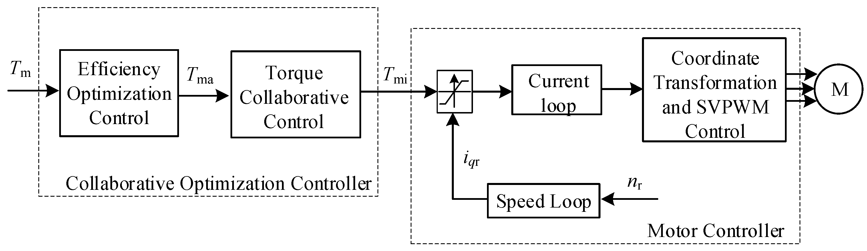
A block diagram of collaborative optimization control-based drive system is shown in
Figure 2, where
Tm is the driver throttle given torque. The vehicle controller is transmitted to the collaborative optimization controller through controller area network (CAN) communication, and the optimized target torques
Tma1 and
Tma2 of the two motor modules are determined according to the efficiency optimization control strategy. Through the torque collaborative control, the optimized torques
Tmi1,
Tmi2 of the two motor modules are obtained, and the optimized torque is transmitted to the two motor controllers through CAN communication to realize the efficiency optimization control and the torque collaborative control.
The AFPMSM of double stator and single rotor can have two modes of operation compared to a general motor. Working mode a: only one stator winding works and its output torque is equal to the given torque of the electric vehicle, while working mode b: the two stator windings work at the same time, and the output torque is half of the given torque. Reasonable switching between the two working modes not only improves the maximum output torque of the motor, but also improves the efficiency of the motor.
In order to determine the switching boundary, firstly, it is necessary to analyze the efficiency of the motor system when the motors are operated in two modes. The efficiency MAP is an important data graph of the motor characteristics, which can reflect the system efficiency distribution of the motor under different speed and torque [
16,
17]. In this paper, the two motor controllers use the same motor control program, and the control algorithm uses
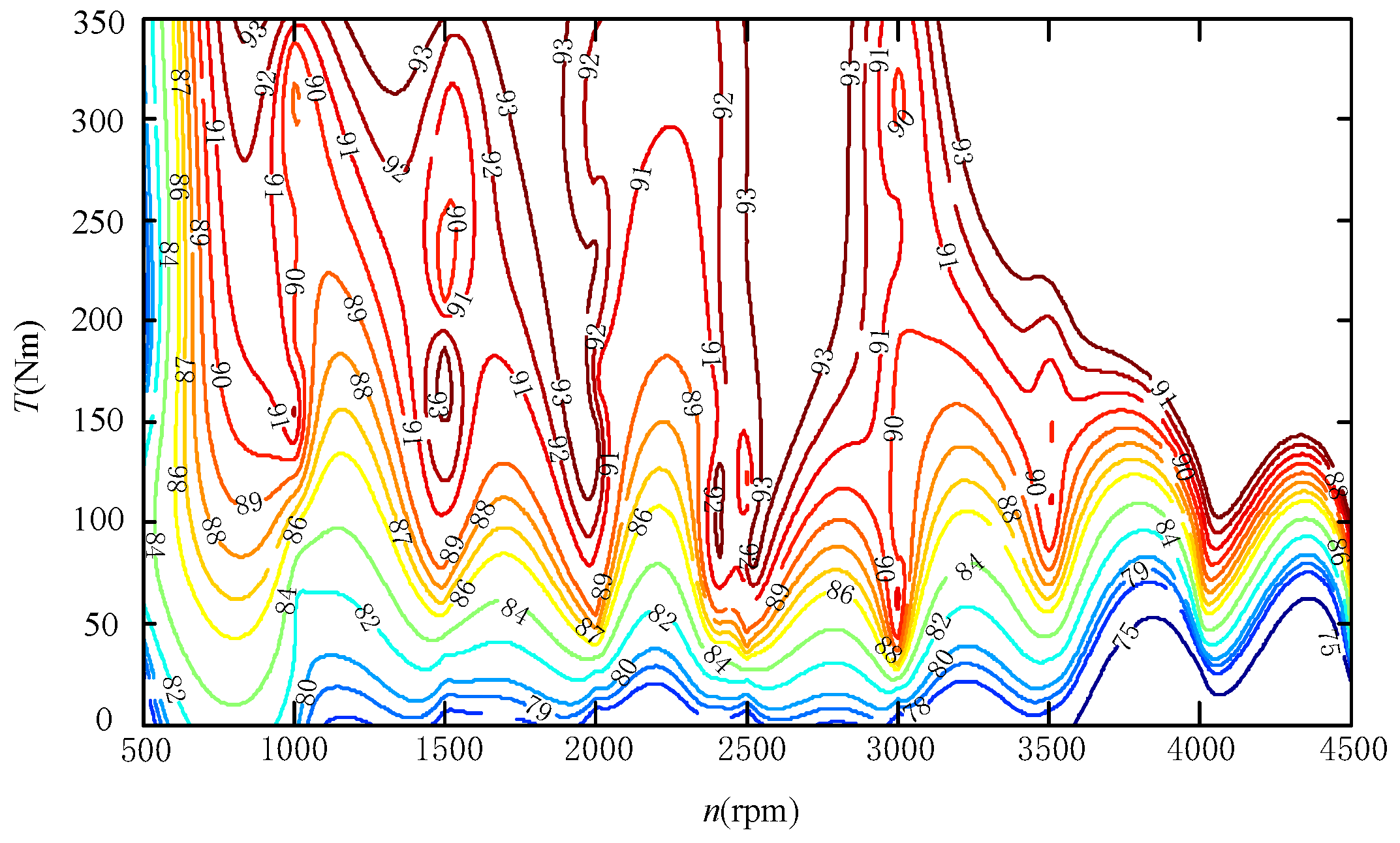
id = 0 vector control to obtain the system efficiency in two working modes through experiments. The experimental test platform will be introduced in the fourth section. The two working modes take 10 speed points, and 10 torque points are taken at each speed point to make a system efficiency MAP, as is shown in
Figure 3.
According to the above two motor system efficiency MAP, if each speed and torque condition takes the higher efficiency points in the two working modes, the system efficiency will be greatly improved. However, when the electric vehicle is actually running, the target vehicle speed and the demand torque are always changing. If the system speed and torque are always changing at the boundary, the system needs to frequently switch between the two working modes, which are not conducive to the stable operation of the electric vehicle. Therefore, the hysteresis comparator is added to prevent the system from switching frequently in two working modes. The switching boundary of the two working modes of the system after adding the hysteresis comparator is shown in
Figure 4.
However, the output torque will fluctuate when the operating mode of the motor system changes. And the frequent sudden change of the given torque will cause the inverter current shock. Therefore, a torque collaborative control strategy based on fuzzy control is proposed to improve torque ripple.
The AFPMSM of double stator and single rotor has two stator winding motor modules. In this paper, the master-slave control is used to realize the collaborative control of the given torque of two motor modules. The motor module 1 is the main motor, and the motor module 2 is the slave motor. The difference between the output value
Tmi1 of the torque collaborative control 1 and the given torque
Tm is taken as a given value of the torque collaborative control 2, that is, the optimized given torque
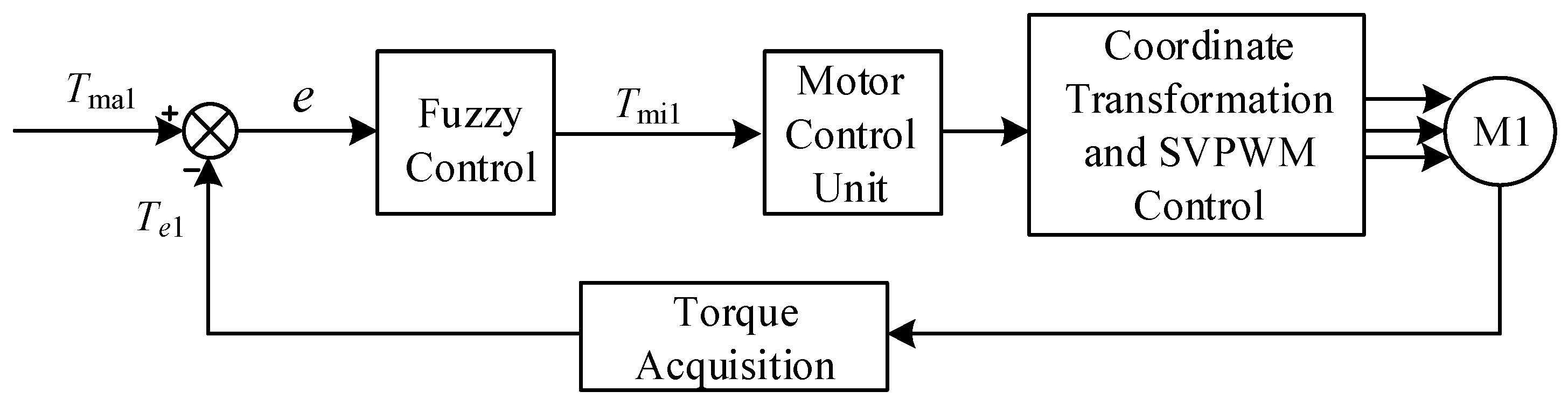
Tmi2 of the motor module 2. The fuzzy controller is used to realize the torque collaborative control strategy. The design method of torque collaborative control 1 is shown in
Figure 5.
The 2D fuzzy controller is selected, and the error signal value e and the error change rate ec are used as the input of the fuzzy controller, and the error signal value is the difference between the optimized target torque Tma1 and the actual torque Te1. The output of the controller is the parameter adjustment amount △kp, △ki, and △kd. The input and output variables have a quantization level of 7. The fuzzy subset is {PB, PM, PS, ZO, NS, NM, NB}, which means {Negative Big, Negative Medium, Negative Small, Zero, Positive Small, Positive Medium, and Positive Big}. The quantitative domain of the error e and the error rate ec is taken as {−3, −2, −1, 0, 1, 2, 3}. The domain of △kp and △kd is [−3,3]. The domain of △ki is [−0.06, 0.06].
The actual error torque output when the system is working may not be in the domain set above. The basic domain of the torque error is [0,350], so the actual output error should be conditioned to the domain [−
N,
N] by the quantization factor, as shown in (8):
The membership function uses a triangular distribution function. Fuzzy rules are established based on the actual operation of the electric vehicle and the experience of motor control. A total of 49 fuzzy rules were established. The fuzzy rule tables of △
kp, △
ki and △
kd are shown in
Table 2,
Table 3 and
Table 4.
The method for defuzzification is centroid method in this paper. The method of defuzzification is as shown in (9). It can be seen from [
18,
19,
20] that the PID (Proportion, integral and differential) control based on fuzzy control is better and more suitable for practical application, compared with the traditional PID control.
4. Research on Sliding Mode Control-Based Vector Control for Electric Vehicle
Electric vehicle drive system needs to have good torque control capability. Therefore, based on the external collaborative optimization control loop, an improved vector control method is proposed, and a current controller and a speed controller are designed based on sliding mode control.
The overall structure diagram of the designed electric vehicle motor drive control system is shown in
Figure 6.
4.1. Design of Second-Order Integral Sliding Mode Current Controller
A new second-order sliding mode control algorithm is used to achieve current control of PMSM. Compared with the traditional control, it has better robustness and dynamic response capability, and it can suppress the “chattering” phenomenon compared with the first-order sliding mode control, thus improving the performance of the PMSM system. According to (1), (2) can be written as:
(10) can be converted to:
Define the current tracking error as:
The current tracking error
ed and
eq are selected as state variables,
ud and
uq are control inputs. The current loop state space equation can be obtained from (10) to (12):
In the formula:
where,
C1 and
C2 can be regarded as disturbance items.
According to (12), under the premise of ensuring the progressive stability and good dynamic performance of the sliding mode, the definition of the sliding surface is:
In (14), k1 and k2 are integral coefficients, which determine the tracking error convergence speed, k1 > 0, k2 > 0. Since the integral term is introduced in the sliding surface, it can be ensured that the current of the motor dq axis approaches the respective current reference settings with good dynamic characteristics, and that the dynamic performance of the sliding mode motion is better.
In order to guarantee the basic three conditions and ensure the control quality, the exponential approach law is chose to design the sliding mode controller.
From (13), (15), and (16) and
idr = 0, it can be calculated:
Calculate and select the control rate as follows:
It is known from the basic principle of the sliding mode variable structure that the design of the sliding mode variable structure system is mainly the selection of the control rate of the sliding mode surface and the sliding mode. When the sliding surface and the control rate are selected, the sliding mode variable structure control system can be fully established. Due to the exponential approach law, the existence and accessibility of the system sliding mode can be ensured.
4.2. Design of Second-Order Integral Sliding Mode Speed Controller
The electric vehicle only uses the speed loop when working in the speed limit mode, and adopts the structure of the internal current loop and the external speed loop. In this case, the performance of the speed regulator will determine the effect of the speed tracking. Sliding mode variable structure control can reduce overshoot when realizing dynamic response of speed. Its robust performance is good, and it is not sensitive to external disturbance, and it can improve the comfort performance of electric vehicles at high speed.
The electric vehicle only uses the speed loop when working in the speed limit mode, and adopts the structure of the external speed loop and the internal current loop, while the performance of the speed regulator will determine the effect of the speed tracking. Sliding mode variable structure control can reduce overshoot when realizing dynamic response of speed. It has good robust performance and is not sensitive to external disturbance, which can improve the comfort performance of electric vehicles at high speed.
For the speed loop control system, the speed error
eω is defined as a state variable, and the state error equation can be expressed as:
where
ωref is the mechanical angular velocity corresponding to the setting limit rotation speed.
The torque equation of the known motor is:
When using
id = 0 vector control, the mathematical model of the PMSM in the dq coordinate system becomes (21):
The speed error of the motor can be obtained from (19), (20) and (21) as follows:
Among them, , , and , c is regarded as the disturbance item.
Like the current loop, the velocity differential error (22) is first-order relative to the velocity error (19), the “chattering” phenomenon generated by the system sliding mode control can be suppressed by the second-order sliding mode control. Define the speed sliding surface as:
The exponential approach law is selected to design the speed sliding mode controller. The sliding surface is guided as:
Bringing the equation of state and the sliding surface equation into account can obtain:
Due to the exponential approach law, the existence and accessibility of the system sliding mode can be ensured.
5. Experiment and Results
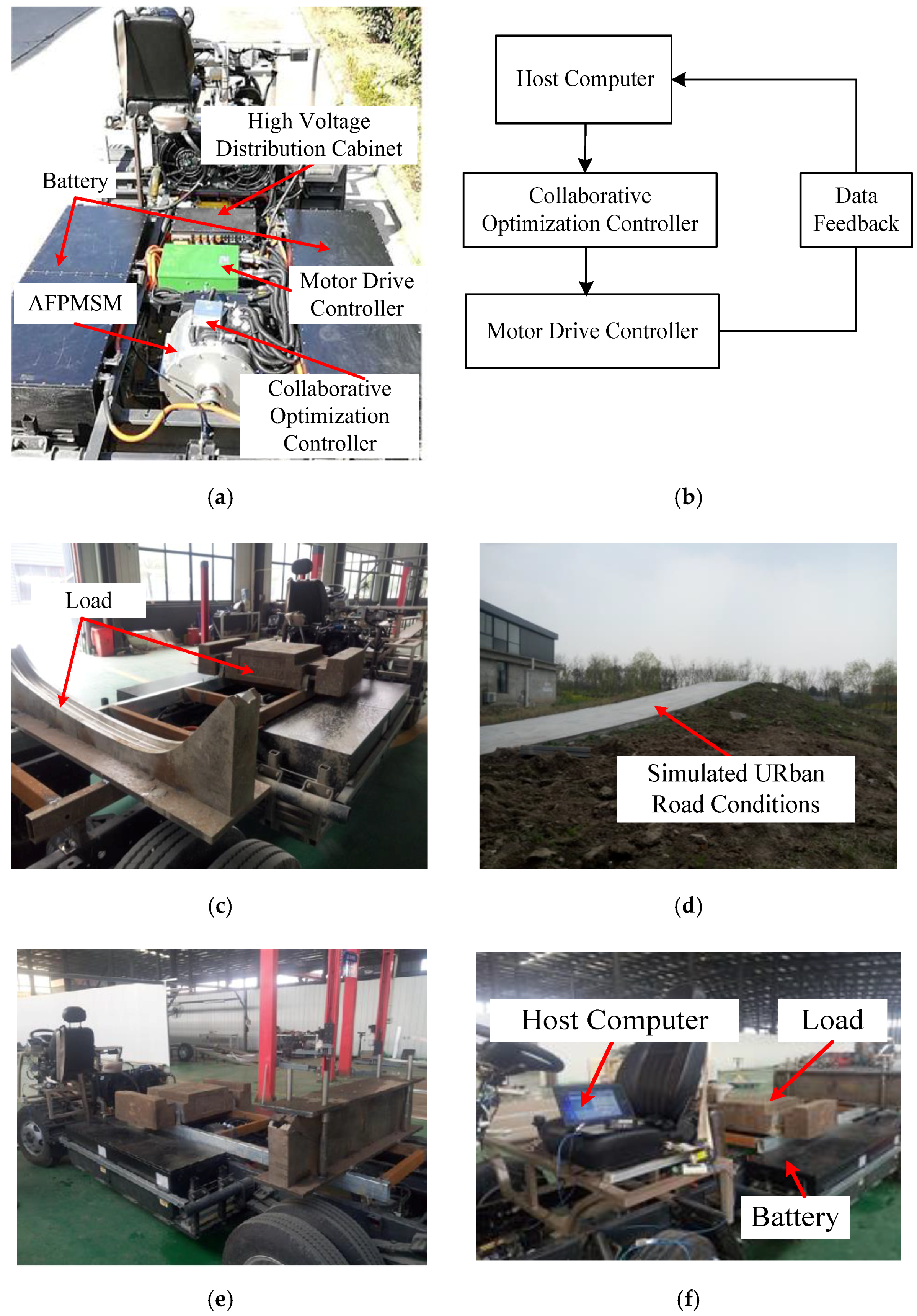
The experiment was carried out under actual road conditions to verify the real performance of the control module designed in this paper. The length of the electric vehicle is 12 m. The weight of the car is 2500 kg. The full load is 1000 kg. The built-in drive motor of electric logistics vehicle is the AFPMSM studied in this paper. The internal structure of the electric logistics vehicle is shown in
Figure 7a, the total look of the electric logistics vehicle is shown in
Figure 7c, the simulated urban road condition is shown in
Figure 7d, and the experimental load is shown in
Figure 7e. The experimental upper computer is shown in
Figure 7f. The experimental block diagram is shown in
Figure 7b. As is shown in
Figure 7b, the given torque is given by the host computer, and the data is transmitted to the cooperative optimization controller through CAN communication. The distributed torque is sent to the motor drive control module through CAN communication to control the AFPMSM motor, and the CAN communication returns the feedback data to the host computer. Among them, the motor drive control
Module has two modules of PI (Proportion and integral) vector control and sliding mode vector control, and determines which module to use according to the actual needs of the experiment. The host computer can store data for subsequent data processing.
5.1. Experiment of Collaborative Optimization Controller
Firstly, the efficiency of the motor system is tested in the two operating modes (normal mode and collaborative optimization control mode) when the speed or torque is changed. Then, the efficiency Map of the AFPMSM system based on collaborative optimization control is obtained under the condition that both the speed and the torque are changed.
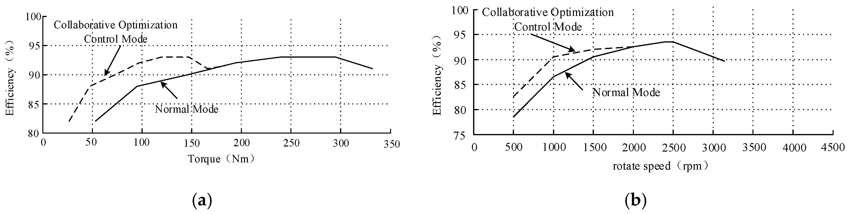
When the rotational speed is constant and the torque is changed, the rotational speed is kept constant at 2000 rpm. The efficiency of the motor is measured under 10 different torque conditions, as is shown in
Figure 8a. It shows that when the rotational speed is 2000 rpm and the torque is low, the efficiency of the motor is significantly higher than that of the motor in the normal mode after the collaborative optimization control is added. When the motor output torque is high, the efficiency of the collaborative optimization control mode is consistent with that in the normal mode.
When the torque is constant and the speed is changed, the output torque is made constant at 200 Nm. The efficiency of the motor is measured at 10 different speeds, as is shown in
Figure 8b. It shows that when the output torque is kept at 200 Nm and the rotational speed is low, the efficiency of the motor system is higher after the synergistic optimization control is added. When the motor is operated at a high speed, the efficiency of the collaborative optimization control mode is consistent with that in the normal mode.
When the torque and the speed both change, 10 speed points are selected, then 10 torque points are took under each speed point, and make the test data into the motor system efficiency MAP. The efficiency MAP of the AFPMSM drive system based on the collaborative optimization control is shown in
Figure 9.
Comparing
Figure 9 with
Figure 3, it can be found that the collaborative optimization control strategy can significantly increase the high efficiency range of the AFPMSM. The system efficiency is increased by about 30% in the efficiency range of more than 90%, and the system efficiency is increased by about 45% in the efficiency range of more than 85%, which verify the correctness of the proposed collaborative optimization control strategy.
5.2. Experiment of Torque Tracking and Speed Limiting
In order to verify the torque tracking and speed limiting performance of the proposed improved electric vehicle vector control system, the AFPMSM operates in single winding operation mode, and the given torque of the upper computer is directly transmitted to the motor controller through CAN communication. The feedback torque is observed by the upper computer, and the data is saved and analyzed. The torque tracking and speed limiting experiments were carried out on the drive control system based on both PI controller and the sliding mode controller.
For torque tracking performance, the given abrupt torque is 100 Nm, and the feedback torque waveform is shown in
Figure 10.
It can be seen from
Figure 10 that the time required for the torque, which is varying from 0 Nm to 100 Nm, of the PI controller-based drive control system to stabilize is about 12 ms, and the overshoot is about 7%. The sliding mode controller-based drive control system takes about 6 ms to track and reach the stability of the torque, the torque overshoot is about 3%, and the fluctuation is basically the same when stable. It proves that the designed sliding mode current loop controller can improve the dynamic performance of the system torque tracking and meet the expected requirements.
For the speed limiting performance, the speed limit is set to 3000 rpm and the given torque is 100 Nm when the system is started. The load torque is 50 Nm. The feedback rotational speed and torque are observed, and its waveform is shown in
Figure 11.
Comparing the two control methods of
Figure 11, it can be seen that the speed waveform and the torque waveform under the condition of the speed limiting can both realize the speed limit. When the PI regulator is used, the rotational speed rising from 0 rpm to 3000 rpm takes 9 s to stabilize. When the sliding mode controller is used, the speed rising to the limit speed takes only 6 s to stabilize, and the speed overshoot is significantly reduced. The torque ripple is basically the same when the speed is stable, which verifies that the proposed vector control can work in torque closed loop mode at low speed and work in double closed loop mode at high speed, and that the designed sliding mode controller can improve system performance.
5.3. Experiment of Acceleration Performance and Endurance Ability
The acceleration performance and endurance ability of the electric vehicle under different control strategies and different experimental conditions were tested separately and averaged after repeated tests. The electric vehicle has a battery capacity of 100 kWh and a full load of 1000 kg. The test data of the electric vehicle from 0 km/h to 100 km/h and the cruising range of the electric vehicle under different working conditions are shown in
Table 5 and
Table 6.
It can be seen from the above two tables that the designed drive system shows good starting acceleration performance and endurance function in the actual operation. The designed sliding mode controller can significantly improve the acceleration performance of the electric vehicle, and the acceleration performance can be improved by about 12% at light load. The designed collaborative optimization control strategy does not improve the cruising range of the electric vehicle when the electric vehicle is overloaded and operates in the high-speed operation mode. However, this strategy can greatly improve the cruising range of electric vehicles under the half load or working in urban conditions. When the electric vehicle is lightly loaded and operating in urban condition, the cruising range has increased by about 15% with the collaborative optimization control strategy.
6. Conclusions
In this paper, a sliding mode vector control system based on collaborative optimization of AFPMSM for electric vehicle is proposed. Firstly, the mathematical model of double-stator and single-rotor AFPMSM is established. The collaborative optimization control strategy is proposed to increase the high efficiency range of electric vehicles and improve the cruising range. The experiment of collaborative optimization controller shows that the proposed control strategy can effectively increase the system efficiency interval. Compared with the three efficiency optimization MAPs, the system efficiency is increased by about 30% in the efficiency range of more than 90%, and the system efficiency is increased by about 45% in the efficiency range of more than 85%. The torque ripple caused by the working mode conversion is improved by fuzzy control.
The speed limit and current vector control strategy based on sliding mode controller is proposed to improve the torque tracking capability, speed limiting characteristics, and operating characteristics. The experiment of torque tracking and speed limiting shows that the proposed speed-limit and current vector controller is better than the traditional PI controller.
The complete vehicle experiment of acceleration performance and endurance ability shows that the acceleration performance of the designed drive control system with both collaborative optimization control and sliding mode vector control, can be improved by about 12% at light load. When the electric vehicle is lightly loaded and operating in urban condition, the cruising range has increased by about 15% with the collaborative optimization control strategy.


