Optimal Design of Permanent Magnet Linear Generator and Its Application in a Wave Energy Conversion System


Abstract
:1. Introduction
2. Level-Set Method
2.1. Principle of Level-Set Method
2.2. The Solution of Level Set Function
3. CPMLG Optimization with the Level-Set Method
- (1)
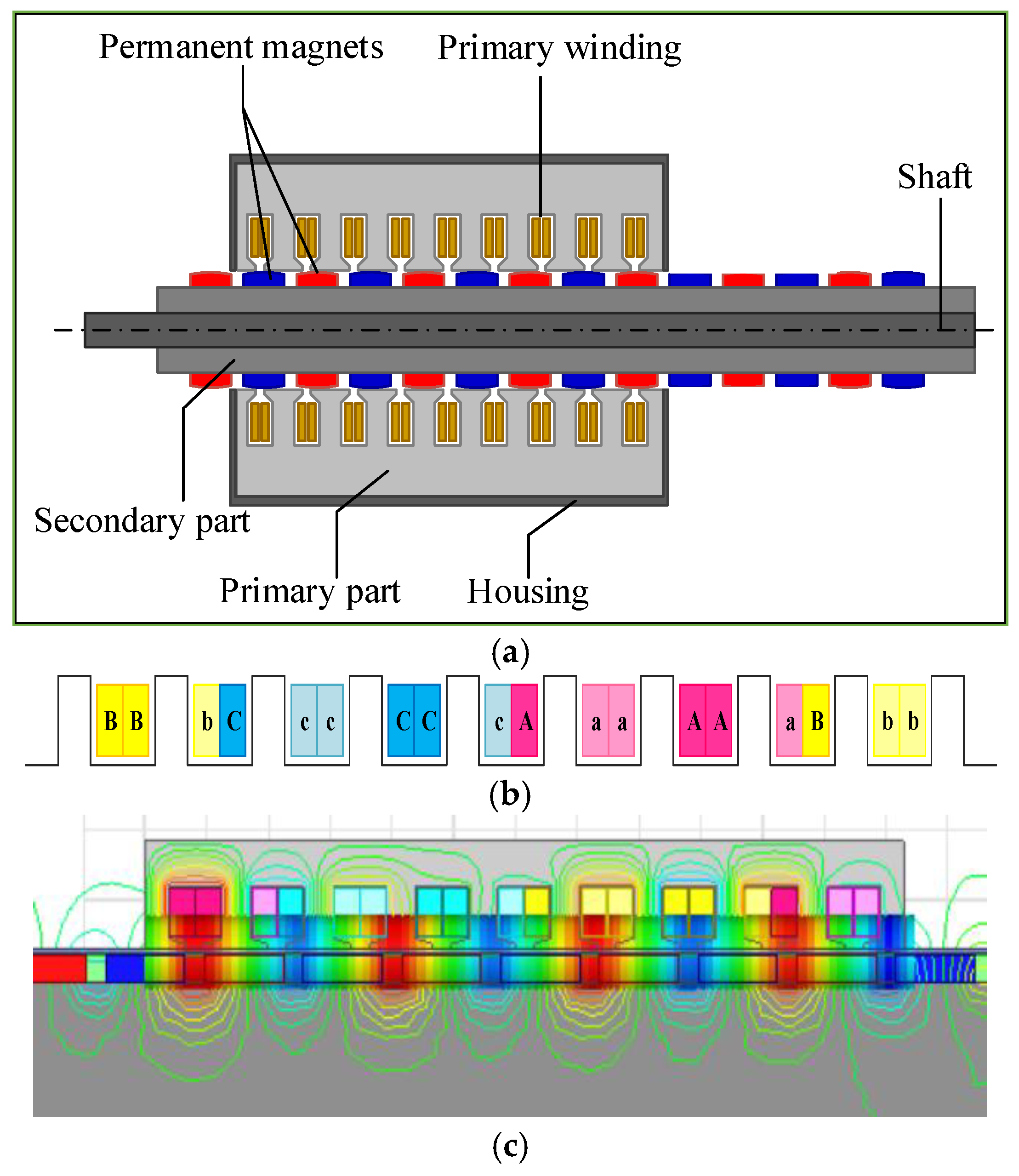
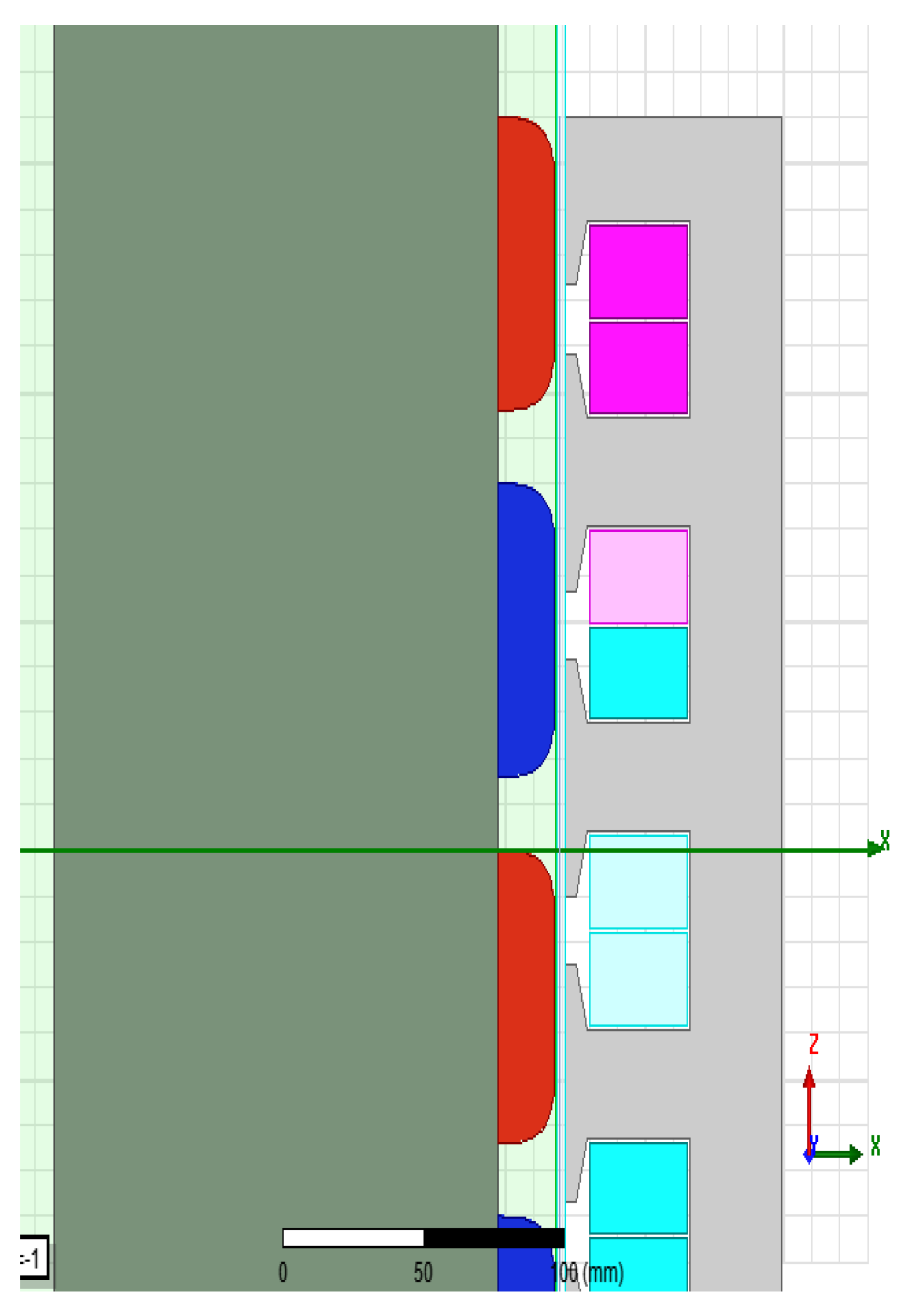
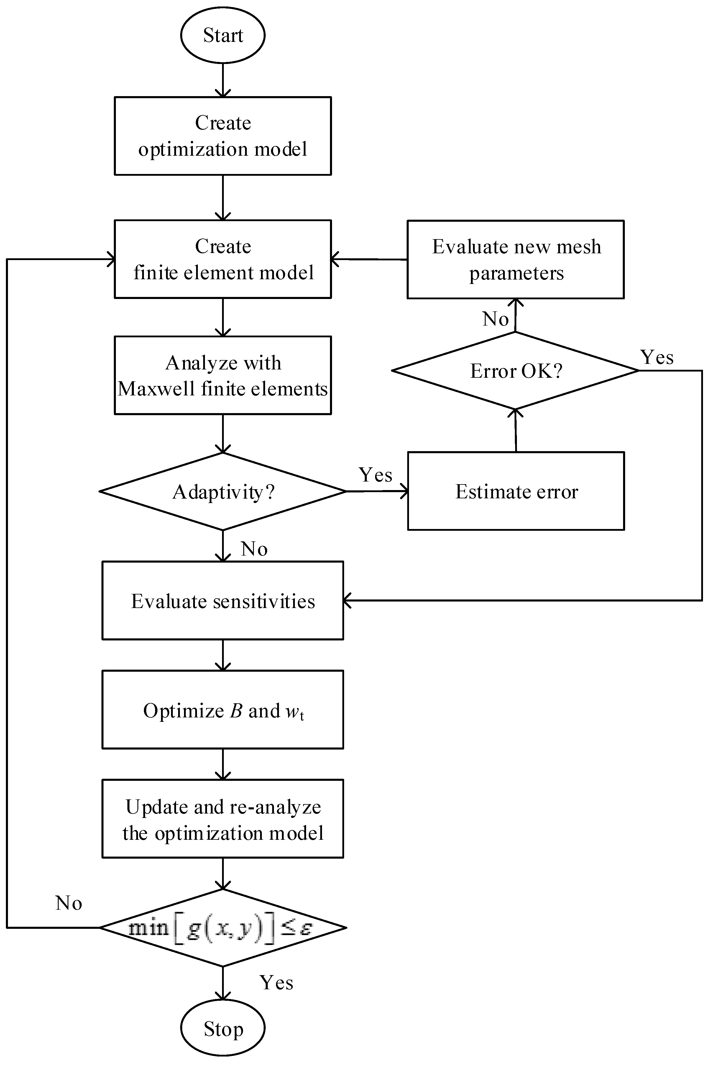
- The objective air gap magnetic field is given by the mathematical analysis method. Appropriate measuring points are predetermined and the points fully reflect the distribution characteristics of the air gap magnetic field. A contour ring is chosen as the initial shape of the PM with the cross-sectional shape being a 64 mm*10 mm rectangular. So, according to Figure 1 and Equation (11), the corresponding matrix of the zero level-set function is characterized by: The PM boundary value being 0, and the external value and the internal value are equal to 1 and −1, respectively. Then, choose another n + 1 variables along the permanent magnet edge evenly to represent the PM shape for optimization. Here, a curvature evolution scheme is applied under the control lyapunov function (CLF)-condition of the Hamilton-Jacobi equation. Using Equation (10), we can get ϕ and Ki.
- (2)
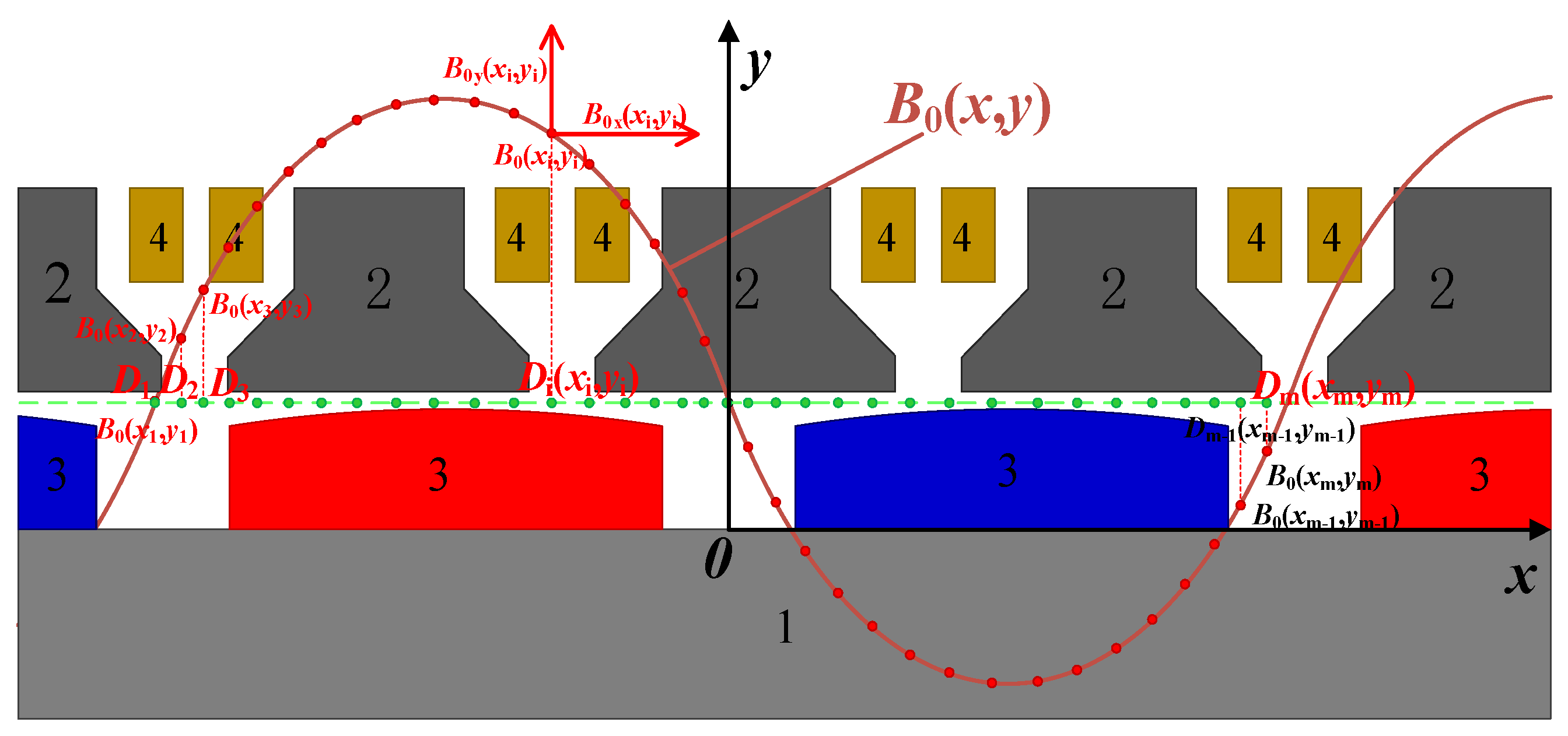
- Then, the coordinates of K0, K1 ... Kn are used to form the profile of the edges of the PMs in ANSYS Maxwell. The magnetic induction density, , at the detection positions, , , ... , , as well as the corresponding x and y axis components of them, and , are obtained. According to , and their target magnetization values, and , we can get the objective function as:
- (3)
- In addition, is denoted as the jth objective function. In this paper, m = 33. It means that the air gap region corresponding to one pole pair is divided into 32 segments. Figure 3 shows the detection points setting of B.
- (4)
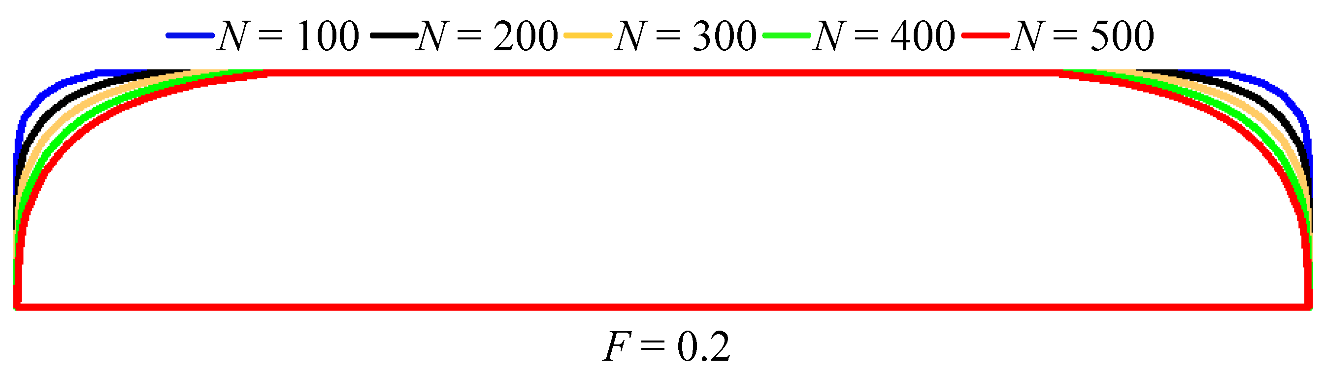
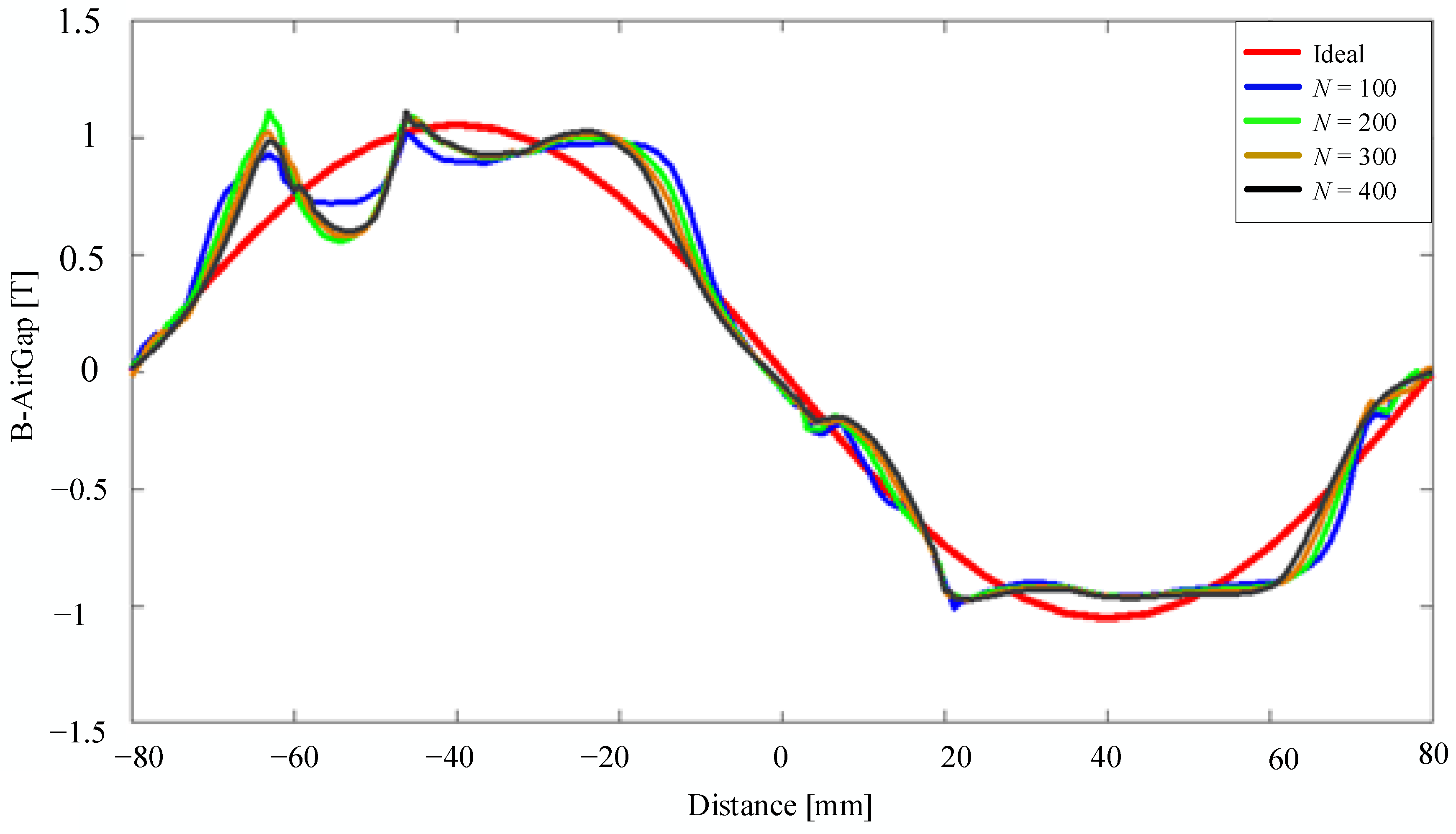
- If the Equation (13) does not hold, then keep F and t unchanged, and repeat the above steps to resolve ϕ and the corresponding , , and until Equation (13) holds. In this design example, and F are set to be 3 and 0.2, respectively. There are five cases of iterations. N is the iteration time and is set to be 100, 200, 300, 400, and 500, respectively. Figure 4 shows the evolution results of the edge of the permanent magnets under five different conditions.
4. Simulation Results and Analysis
5. Discussions
6. Conclusions
Author Contributions
Acknowledgments
Conflicts of Interest
References
- Balitsky, P.; Verao Fernandez, G.; Stratigaki, V.; Troch, P. Assessment of the Power Output of a Two-Array Clustered WEC Farm Using a BEM Solver Coupling and a Wave-Propagation Model. Energies 2018, 11, 2907. [Google Scholar] [CrossRef]
- Wu, J.; Yao, Y.; Zhou, L.; Göteman, M. Latching and Declutching Control of the Solo Duck Wave-Energy Converter with Different Load Types. Energies 2017, 10, 2070. [Google Scholar] [CrossRef]
- Guardeño, R.; Consegliere, A.; López, M.J. A Study about Performance and Robustness of Model Predictive Controllers in a WEC System. Energies 2018, 11, 2857. [Google Scholar] [CrossRef]
- Franzitta, V.; Curto, D.; Milone, D.; Rao, D. Assessment of Renewable Sources for the Energy Consumption in Malta in the Mediterranean Sea. Energies 2016, 9, 1034. [Google Scholar] [CrossRef]
- Jones, C.; Chang, G.; Raghukumar, K.; McWilliams, S.; Dallman, A.; Roberts, J. Spatial Environmental Assessment Tool (SEAT): A Modeling Tool to Evaluate Potential Environmental Risks Associated with Wave Energy Converter Deployments. Energies 2018, 11, 2036. [Google Scholar] [CrossRef]
- Feng, N.; Yu, H.; Hu, M.; Liu, C.; Huang, L.; Shi, Z. A Study on a Linear Magnetic-Geared Interior Permanent Magnet Generator for Direct-Drive Wave Energy Conversion. Energies 2016, 9, 487. [Google Scholar] [CrossRef]
- Huang, L.; Hu, M.; Chen, Z.; Yu, H.; Liu, C. Research on a Direct-Drive Wave Energy Converter Using an Outer-PM Linear Tubular Generator. IEEE Trans. Magn. 2017, 53, 8104704. [Google Scholar] [CrossRef]
- Xia, T.; Yu, H.; Chen, Z.; Huang, L.; Liu, X.; Hu, M. Design and Analysis of a Field-Modulated Tubular Linear Permanent Magnet Generator for Direct-Drive Wave Energy Conversion. IEEE Trans. Magn. 2017, 53, 8103904. [Google Scholar] [CrossRef]
- Zhang, J.; Yu, H.; Shi, Z. Design and Experiment Analysis of a Direct-Drive Wave Energy Converter with a Linear Generator. Energies 2018, 11, 735. [Google Scholar] [CrossRef] [Green Version]
- Zhang, C.; Chen, F.; Li, L.; Xu, Z.; Liu, L.; Yang, G.; Lian, H.; Tian, Y. A Free-Piston Linear Generator Control Strategy for Improving Output Power. Energies 2018, 11, 135. [Google Scholar] [CrossRef]
- Prudell, J.; Stoddard, M.; Amon, E.; Brekken, T.K.A.; von Jouanne, A. A Permanent-magnet Tubular Linear Generator for Ocean Wave Energy Conversion. IEEE Trans. Ind. Appl. 2010, 46, 2392–2400. [Google Scholar] [CrossRef]
- Fang, H.W.; Wang, D. Design of Permanent Magnet Synchronous Generators for Wave Power Generation. Trans. Tianjin Univ. 2016, 22, 396–402. [Google Scholar] [CrossRef]
- Farrok, O.; Islam, M.R.; Sheikh, M.R.I.; Guo, Y.G.; Zhu, J.G.; Xu, W. A Novel Superconducting Magnet Excited Linear Generator for Wave Energy Conversion System. IEEE Trans. Appl. Superconduct. 2016, 26, 5207105. [Google Scholar] [CrossRef]
- Zhu, Z.Q.; Hu, J. Electrical Machines and Power Electronic Systems for High-Power Wind Energy Generation Applications: Part II- Power Electronics and Control Systems. Int. J. Comput. Math. Electr. Electr. Eng. 2013, 32, 7–33. [Google Scholar] [CrossRef]
- Liu, C.Y.; Yu, H.T.; Hu, M.Q.; Liu, Q.; Zhou, S.G.; Huang, L. Research on a Permanent Magnet Tubular Linear Generator for Direct Drive Wave Energy Conversion. IET Renew. Power Gener. 2014, 8, 281–288. [Google Scholar] [CrossRef]
- Tom, N.; Yeung, R.W. Experimental Confirmation of Nonlinear-Model-Predictive Control Applied Offline to a Permanent Magnet Linear Generator for Ocean-Wave Energy Conversion. IEEE J. Ocean. Eng. 2016, 41, 281–295. [Google Scholar]
- Sethian, J.A. Variational Methods for Tree Surface Interfaces; Numerical Methods for Propagating: New York, NY, USA, 1987; pp. 155–164. [Google Scholar]
- Osher, S.J.; Sethian, J.A. Fronts Propagating with Curvature Dependent Speed: Algorithms Based on Hamilton-Jacobi Formulation. J. Comput. Phys. 1988, 79, 12–49. [Google Scholar] [CrossRef]
- Ruiz-España, S.; Díaz-Parra, A.; Arana, E.; Moratal, D. A Fully Automated Level-Set Based Segmentation Method of Thoracic and Lumbar Vertebral Bodies in Computed Tomography images. In Proceedings of the 2015 37th Annual International Conference of the IEEE Engineering in Medicine and Biology Society (EMBC), Milan, Italy, 25–29 August 2015; pp. 3049–3052. [Google Scholar]
- Kim, Y.S.; Park, I.H. Topology Optimization of Rotor in Synchronous Reluctance Motor Using Level Set Method and Shape Design Sensitivity. IEEE Trans. Appl. Supercond. 2010, 20, 1093–1096. [Google Scholar]
- Putek, P.; Paplicki, P.; Pałka, R. Low Cogging Torque Design of Ppermanent Magnet Machine Using Modified Multi-Level Set Method with Total Variation Regularization. IEEE Trans. Magn. 2014, 50, 657–660. [Google Scholar] [CrossRef]
- Kwack, J.; Min, S.; Hong, J.P. Optimal Stator Design of Interior Permanent Magnet Motor to Reduce Torque Ripple Using the Level Set Method. IEEE Trans. Magn. 2010, 46, 2108–2111. [Google Scholar] [CrossRef]
- Fang, H.W.; Chen, H.X. Design of Cylindrical Permanent Magnet Linear Generator for Ocean Wave Energy Conversion with Level-Set Method. In Proceedings of the Compumag: Conference of Electromagnetic Fields (Compumag 2017), Seoul, Korea, 18–22 June 2017. [Google Scholar]
- Fang, H.W.; Jin, L.T. A Wave Frequency Adaptive Wave Energy Conversion System. Chinese Patent 201810070154, 6 January 2018. [Google Scholar]


| Structure Parameters | Value | Structure Parameters | Value |
|---|---|---|---|
| Poles p | 8 | Primary yoke height hj (cm) | 3.3 |
| Pole pitch τ (cm) | 8 | Primary tooth width bt (cm) | 2.37 |
| Pole-arc coefficient ξ | 0.8 | Armature effective length l (cm) | 158 |
| Primary slots’ number | 9 | Air gap width δ (cm) | 0.4 |
| Permanent magnet thickness d (cm) | 2 | Secondary core thickness d2 (cm) | 16 |
| Width of slot bs (cm) | 4.3 | Width of yoke wt (cm) | 2.1 |
| i | Di | Bx(xi,yi)/T | By(xi,yi)/T |
|---|---|---|---|
| 1 | D1 | 0 | 0 |
| 2 | D2 | 0.0042 | 0.1613 |
| 3 | D3 | 0.0061 | 0.4108 |
| 4 | D4 | 0.0089 | 0.8153 |
| 5 | D5 | 0.0106 | 0.8039 |
| 6 | D6 | 0.0276 | 0.6216 |
| 7 | D7 | 0.0160 | 0.6447 |
| 8 | D8 | 0.0279 | 1.0606 |
| 9 | D9 | 0.0626 | 0.9632 |
| 10 | D10 | 0.4018 | 0.8331 |
| 11 | D11 | 0.0529 | 0.9581 |
| 12 | D12 | 0.2064 | 0.9991 |
| 13 | D13 | 0.0417 | 0.9743 |
| 14 | D14 | 0.0101 | 0.7552 |
| 15 | D15 | 0.0062 | 0.3950 |
| 16 | D16 | 0.0034 | 0.1381 |
| 17 | D17 | −0.0011 | −0.0375 |
| 18 | D18 | −0.0799 | −0.1977 |
| 19 | D19 | −0.0084 | −0.2380 |
| 20 | D20 | −0.0075 | −0.4606 |
| 21 | D21 | −0.0074 | −0.8741 |
| 22 | D22 | −0.1429 | −0.9562 |
| 23 | D23 | −0.2201 | −0.9101 |
| 24 | D24 | −0.5251 | −0.7700 |
| 25 | D25 | −0.2306 | −0.9326 |
| 26 | D26 | −0.3441 | −0.9018 |
| 27 | D27 | −0.4879 | −0.8190 |
| 28 | D28 | −0.7347 | −0.6013 |
| 29 | D29 | −0.0795 | −0.9223 |
| 30 | D30 | −0.0100 | −0.7101 |
| 31 | D31 | −0.0050 | −0.3483 |
| 32 | D32 | −0.0034 | −0.0928 |
| 33 | D33 | −0.0006 | −0.0074 |
© 2018 by the authors. Licensee MDPI, Basel, Switzerland. This article is an open access article distributed under the terms and conditions of the Creative Commons Attribution (CC BY) license (http://creativecommons.org/licenses/by/4.0/).
Share and Cite
Fang, H.-w.; Song, R.-n.; Xiao, Z.-x. Optimal Design of Permanent Magnet Linear Generator and Its Application in a Wave Energy Conversion System. Energies 2018, 11, 3109. https://doi.org/10.3390/en11113109
Fang H-w, Song R-n, Xiao Z-x. Optimal Design of Permanent Magnet Linear Generator and Its Application in a Wave Energy Conversion System. Energies. 2018; 11(11):3109. https://doi.org/10.3390/en11113109
Chicago/Turabian StyleFang, Hong-wei, Ru-nan Song, and Zhao-xia Xiao. 2018. "Optimal Design of Permanent Magnet Linear Generator and Its Application in a Wave Energy Conversion System" Energies 11, no. 11: 3109. https://doi.org/10.3390/en11113109
APA StyleFang, H.-w., Song, R.-n., & Xiao, Z.-x. (2018). Optimal Design of Permanent Magnet Linear Generator and Its Application in a Wave Energy Conversion System. Energies, 11(11), 3109. https://doi.org/10.3390/en11113109