Article

Internet of Things Platform for Energy Management in Multi-Microgrid System to Improve Neutral Current Compensation

1
Queensland Micro- and Nano Centre, Griffith University, Brisbane, QLD 4111, Australia
2
School of Engineering, Macquarie University, Sydney, NSW 2109, Australia
3
Network Development Department, ElectraNet, Adelaide, SA 5000, Australia
4
National Planning Department, AEMO, Melbourne, VIC 3000, Australia
*
Author to whom correspondence should be addressed.
Energies 2018, 11(11), 3102; https://doi.org/10.3390/en11113102
Submission received: 12 October 2018 / Revised: 6 November 2018 / Accepted: 6 November 2018 / Published: 9 November 2018

Abstract

:
In this paper, an Internet of Things (IoT) platform is proposed for Multi-Microgrid (MMG) system to improve unbalance compensation functionality employing three-phase four-leg (3P-4L) voltage source inverters (VSIs). The two level communication system connects the MMG system, implemented in Power System Computer Aided Design (PSCAD), to the cloud server. The local communication level utilizes Modbus Transmission Control Protocol/Internet Protocol (TCP/IP) and Message Queuing Telemetry Transport (MQTT) is used as the protocol for global communication level. A communication operation algorithm is developed to manage the communication operation under various communication failure scenarios. To test the communication system, it is implemented on an experimental testbed to investigate its functionality for MMG neutral current compensation (NCC). To compensate the neutral current in MMG, a dynamic NCC algorithm is proposed, which enables the MGs to further improve the NCC by sharing their data using the IoT platform. The performance of the control and communication system using dynamic NCC is compared with the fixed capacity NCC for unbalance compensation under different communication failure conditions. The impact of the communication system performance on the NCC sharing is the focus of this research. The results show that the proposed system provides better neutral current compensation and phase balancing in case of MMG operation by sharing the data effectively even if the communication system is failing partially.

1. Introduction

The neutral current existence in the three-phase (3P) four-leg (4L) distribution systems is common, mainly due to the unbalance load characteristics. The linear and non-linear single-phase loads in the low voltage networks are usually distributed unequally and this can lead to excessive rise of the neutral current. Unwarranted neutral current of commercial loads can cause damages to the distribution transformer and neutral conductor as well as rising electrical safety concerns at the point of common coupling (PCC) [1]. In order to mitigate the negative impact of high neutral current on the distribution network, various unbalance compensation devices with active and passive control functions are proposed in the literature [2]. Active unbalance compensators such as 1P and 3P-4L converters can control the neutral current directly [3], where the 3P-4L voltage source inverter (VSI) provides better unbalance compensation than other active and passive methods [4]. Traditionally, a fixed portion of the 3P-4L converter capacity is specified to compensate the neutral current. However, the drawback of this method is in case of higher neutral current compensation (NCC) necessity, where it can lead to increased capacity of the 3P-4L compensator [5]. Authors in Reference [6] employed the 3P-4L VSI with PV installation to compensate for the neutral current but case scenarios for network interaction with different loads are not presented. A fixed capacity neutral current compensation method employing 3P-4L VSI under various load scenarios for network contingencies cases is proposed in Reference [7]. Furthermore, the 3P-4L VSI is used to eliminate the leakage current from PV installations [8]. However, none of these researches have considered higher capacity requirement. Authors in Reference [9] propose a dynamic capacity distribution method to compensate for the neutral current utilizing the maximum capacity of the VSI in a Microgrid (MG) but no communication system in presented. Authors in References [10,11] have employed conservative power theory to share the residual neutral current among the VSIs in an MG. Although a communication system have been employed, its operational details are not presented. Cloud-based Internet of Things (IoT) platforms to manage energy of buildings as MGs are presented in References [12,13,14,15,16]. In these articles, hierarchical communication platforms are implemented but reliability of the platform in case of losing the connection to the cloud is not investigated. The cloud-based Energy Management System (EMS) proposed in these studies would not operate if the communication to the cloud were disturbed or failed. Authors in Reference [17] have proposed a hierarchical communication platform for resource allocation in smart buildings where unreliability of the communication platform is considered. Although unreliability of the system is presented in this work, the communication operating system is not explained in detail and different modes of the communication system operation are not discussed.
In this paper, a dynamic neutral current compensation method for a Multi-Microgrid (MMG) EMS utilizing a hierarchical communication system is proposed. In the proposed method, the smart VSIs share the available neutral current after the active and reactive power operation for higher capacity unbalance compensation. In order to share the remaining capacity between the MGs, a two-level communication system is designed to transfer data in the MMG. The MMG system is implemented in PSCAD/EMTDC [18] software using real solar irradiance data, load data from commercial buildings, local communication level (Modbus protocol) and global communication level (MQTT protocol and cloud communication). To the authors’ best knowledge, the proposed dynamic NCC method with a 3P-4L Photovoltaic (PV)-VSI system for a MMG system with detailed communication system has not been reported in previous papers. The dynamic neutral current compensation for an MG is designed based on [9] and the primary design of the communication system is taken from [3].
The contributions of this paper are listed below:
  • develop and implement an improved dynamic NCC method for MMG operation
  • propose a hierarchical communication platform linking traditional communication layer to IoT operation layer
  • present contribution of IoT in MMG operation
  • propose communication system operation algorithm for MMG
  • investigate the role of communication delay on NCC in MMG operation
The rest of the paper is as follows. Section 2 describes the system under study and formulates the problem. In Section 3, the dynamic NCC algorithm for the MMG is explained. Furthermore, the two-level communication system is presented in Section 4. Section 5 is specified to the communication system operation algorithm and its operation modes. The results are explained and discussed in Section 6 and Section 7. Future work is included in Section 7 as well. Finally, paper concludes with Section 8.

2. System Description

The MMG system consists of n MGs, where each MG is equipped with a 3P-4L PV-VSI system as illustrated in Figure 1. All of the MGs are connected to each other in a distribution network, as the 11 kV/420 V downgrades the MV to low voltage (LV) distribution network. The MGs are connected to the neighbouring MGs through the AC bus to transfer active and reactive power and use the excess power for NCC. On the other hand, a hierarchical communication system transfers data in the MMG. Each MG has its PV installation, where it is connected to the DC bus of the VSI and the DC-link capacitor regulates the DC bus voltage. The VSIs are connected to the grid via an LCL filter and an L filter in the fourth leg to remove the harmonics. The commercial buildings are modelled as single-phase R-L combinations, where the actual data of load consumption of MGs, taken from the university monitoring system [19], is employed to model the MMG loads.
The VSI is modelled to provide stable DC and AC side voltage and current. The mathematical model of the PV-VSI system is represented as in Reference [9]:
d d t I f ( d , q ) = V d c L f d d , q r f L f I f ( d , q ) R d L f ( I f ( d , q ) I g ( d , q ) ) V c f ( d , q ) L f ± ω I f ( q , d )
d d t I g ( d , q ) = V c f ( d , q ) L g r g L g I g ( d , q ) + R d L g ( I f ( d , q ) I g ( d , q ) ) V g ( d , q ) L g ± ω I g ( q , d )
d d t V c f ( d , q ) = I f ( d , q ) C f I g ( d , q ) C f ω V c f ( q , d )
d d t V d c = I p v C d c I f ( d , q , 0 ) d ( d , q , 0 ) C d c
d d t I f 0 = 1 L f + 3 L f n V d c d 0 r f + 3 r f n L f + 3 L f n I f 0 R d L f + 3 L f n ( I f 0 I g 0 ) V c f 0 L f + 3 L f n
d d t I g 0 = 1 L g + 3 L g n V c f 0 R g + 3 r g n L g + 3 L g n I g 0 + R d L g + 3 L g n ( I f 0 I g 0 ) V g 0 L g + 3 L g n
d d t V c f 0 = I f 0 C f I g 0 C f
I f n = 3 I f 0
where f stands for filter and g for grid. L g ,   R g ,   L g n   and   R g n are transmission line inductance and resistance and neutral conductor inductance and resistance respectively. Active ( I d ) and reactive current ( I q ) components are used in the control system to control active and reactive power operation as well as NCC. The general schematic of the control system is shown in Figure 2.

3. Multi-Microgrid Control System

This MMG control system is designed to compensate for the neutral current after active and reactive power operation. In the process of compensation, the MGs share their data to use their excess neutral current for other MGs. The PV-VSI apparent power is as follows:
S V S I = P + j Q + 3 P 0 = 3 2 ( V d i I f d i V d i I f q i ) + 3 V 0 i I f 0 i
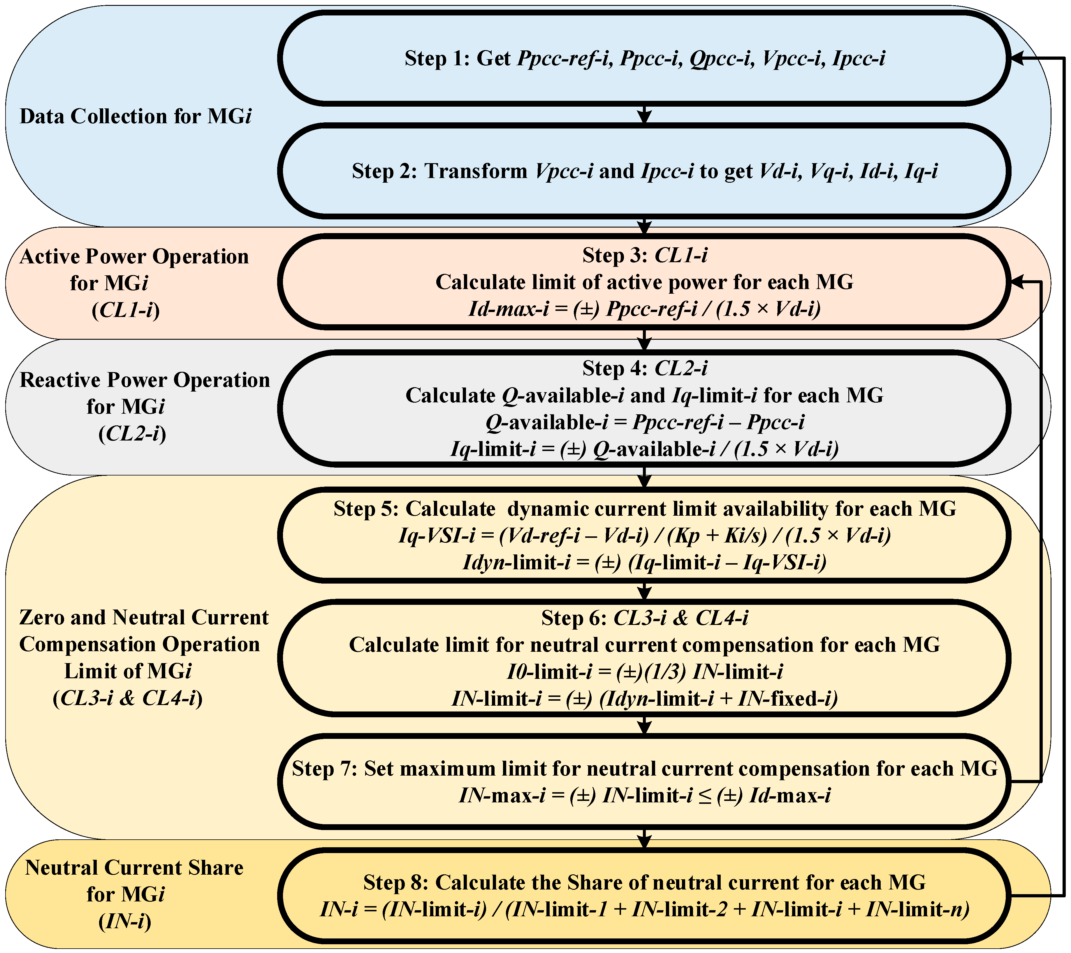
The dynamic NCC algorithm for MMG goes through different steps of operation, where in each step the current limit (CL) is set for the specific operation. Applying the dynamic NCC algorithm, the voltage and current unbalance compensation improves due to the higher capacity for neutral current compensation. The steps are illustrated as in Figure 3.

3.1. Data Collection

The first step of the dynamic NCC method is to collect the required data from the MGs. The data to collect for i th MG is the reference active power at PCC ( P p c c r e f i ), active power at PCC ( P p c c i ), reactive power at PCC ( Q p c c i ), voltage at PCC ( V p c c i ) and current at PCC ( I p c c i ). After gathering all the required data, the second step is to transform V p c c i and I p c c i from a b c to d q 0 frame (i.e., V d i , V q i ,   I d i and I q i ).

3.2. Active Power Operation

After data collection and transformation, the next step is to formulate the active power operation for setting the current limit (CL) for active power ( C L 1 i ) for MG i . The main purpose of this step is to maximize the usage of PV capacity for active power operation. The active power CL is formulated as:
C L 1 i = I d max i = ( ± ) P p c c r e f i / ( 1.5 × V d i )

3.3. Reactive Power Operation

As the next step of the operation, the available reactive power ( Q available i ) and CL for reactive power ( C L 2 i ) for MG i is set. This step would have zero operation limit during the full PV generation period. The voltage at PCC is regulated within limit of ± 6 % . The available reactive power and reactive power CL are expressed as:
Q available i = P p c c r e f i P p c c i
C L 2 i = I q limit i = ( ± ) Q available i / ( 1.5 × V d i )

3.4. Neutral Current Compensation

After active and reactive power operation, the remaining capacity is specified to NCC. In order to use most of the remaining capacity, the dynamic current limiter is designed to set the limits for the neutral current. It is calculated as:
I q V S I i = ( V d r e f i V d i ) ( K p + K i / s ) / ( 1.5 × V d i )
I d y n limit i = ( ± ) I q limit i I q V S I i
If active and reactive power utilize the full capacity of the PV-VSI, the limits of neutral current would be zero. Otherwise, the limits are calculated as:
C L 3 i = I N limit i = ( ± ) I d y n limit i + I N fixed i
C L 4 i = I 0 limit i = ( ± ) ( 1 / 3 ) I N limit i
The maximum neutral current limit is set to prevent damaging the VSIs in MGs as:
I N max i = ( ± ) I N limit i I d max i

3.5. Neutral Current Compensation + Sharing

After setting the neutral current limit for MG i , it is required to define the neutral current share of each MG in the MMG system. Using the communication system, MGs are updated about other MGs NCC limits. Then, the control system sets the shared neutral current of each MG in the MMG operation. The NCC for MMG is formulated as:
I N i = I N l i m i t i i = 1 n I N l i m i t i

4. Multi-Microgrid Internet of Things Platform

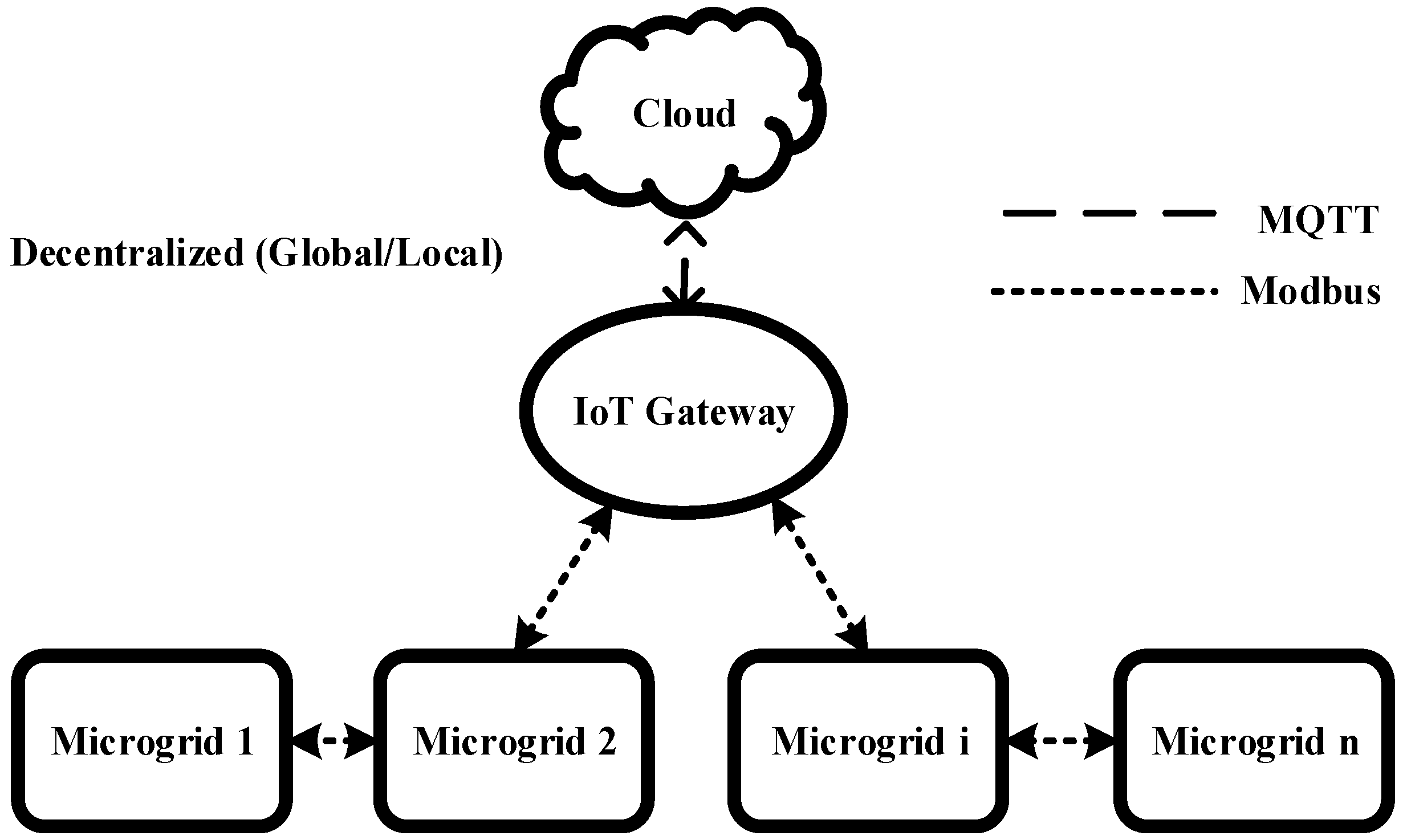
In the MMG system, MGs need to share the data to update the control references. Thus, a communication system is required to transfer the information between the MGs. Most of the existing industrial devices use traditional communication protocols such as Modbus and CAN Bus. On the other hand, with the development of smart grids, the role of internet gets more important. The Internet of Things (IoT) protocols such as Message Queue Telemetry Transport (MQTT) [20] and Advanced Message Queuing Protocol (AMQP) [21] transfer the data from the lower communication levels to the cloud networks. In order to be able to get the benefits of the state of the art IoT technologies in power industry and at the same time upgrade the existing communication systems of MGs, a hierarchical communication system is proposed. In this system, there are two levels of communication; that is, global and local. The local communication level connects the MGs locally, where in this study; Modbus TCP/IP is utilized as the local communication protocol. On the other hand, the global communication level connects the MMG system to the cloud server through MQTT protocol. The main advantage of the two-level communication system is redundancy in case of failure. In other words, the MMG system continues operating even if part of the communication system fails. The general schematic of the hierarchical communication system is presented in Figure 4.

4.1. Local Communication Level

This layer of communication connects all the MGs to each other and is mainly utilized in case of global communication failure. There are different communication protocols to employ for this purpose. In this study, Modbus TCP/IP is used for local communication level. The reason to choose Modbus is the popularity of this communication protocol in measurement and power electronic devices.

Modbus TCP/IP

Modbus communication protocol is the de-facto automation standard used for supervision and control of industrial equipment. As a server/client communication protocol, Modbus is transmitted over several physical links such as RS-232, RS-485 and TCP/IP with the standard port of 502. In Modbus TCP/IP, five layers of Modbus application layer, transmission control protocol (TCP), internet protocol (IP), data link and a physical layer form the internet model [22]. Sending the messages via Modbus TCP/IP, devices, either client or server, talk to each other via the IP addresses. However, the client initiates all the messages. Modbus messaging service provides the capability to read and write data using either single bit or 16-bit words [19].
In Modbus Communication, not all the messages are sent or received within the specified time-period. A TCP packet is retransmitted if its loss has been detected. To realize if a data packet is lost or delayed, a Round-Trip Time (RTT) is measured after sending every packet that is not a retransmission. The RTT is the time taken for a packet to reach the remote device and to get back an acknowledgement to the sending device. The value of the RTT for Modbus TCP/IP is set to be 500 milliseconds in this research based on the network topology and devices performance. Thus, if the RTT takes more than 500 ms, it is counted as time out [22].

4.2. Global Communication Level

In this layer of the proposed hierarchical communication architecture, MGs exchange information using a cloud-based IoT platform. This layer receives data from the local communication layer and connects multiple MGs to each other for NCC purpose. MQTT, which is a publisher-subscriber machine-to-machine messaging protocol, is adopted to realize MMG communications. An online cloud-based platform, which offers easy-to-integrate features for MATLAB interfacing, is employed to post-process the MMG data. MQTT is utilized in this work to realize the messaging among the MG controllers via cloud services. The reason to choose MQTT as the operating protocol of this work compared to other application-layer protocols (e.g., CoAP, AMQP, DDS, XMPP, etc.) are its high network bandwidth efficiency, secure compatibility with cloud services, low power consumption and customizability of topics for the users [21].

4.2.1. MQTT

MQTT is a messaging protocol over TCP/IP with the standard port 1883 set to receive all incoming MQTT messages. MQTT messaging consists of three key players.
  • MQTT publisher
  • MQTT subscriber
  • MQTT broker
MQTT publisher and subscriber are not connected to each other by IP address and do not run simultaneously. A middle player named MQTT Broker connects to the publisher and the subscriber by IP address and distributes the incoming published messages accordingly with ability to handle thousands of concurrent clients [20]. A generic format of an MQTT topic string is indicated below:
DataTypeName / IEDName / MicrogridNam
MQTT is the favoured messaging protocol for environments with embedded resource-constrained devices such as MGs [23]. Each Intelligent Electronic Device (IED) or MG controller, with a running MQTT library, could be a potential MQTT publisher or subscriber. MMG publishers and subscribers are developed using python programming language and Paho libraries [24].

4.2.2. HTTP Protocol for Cloud Interactions

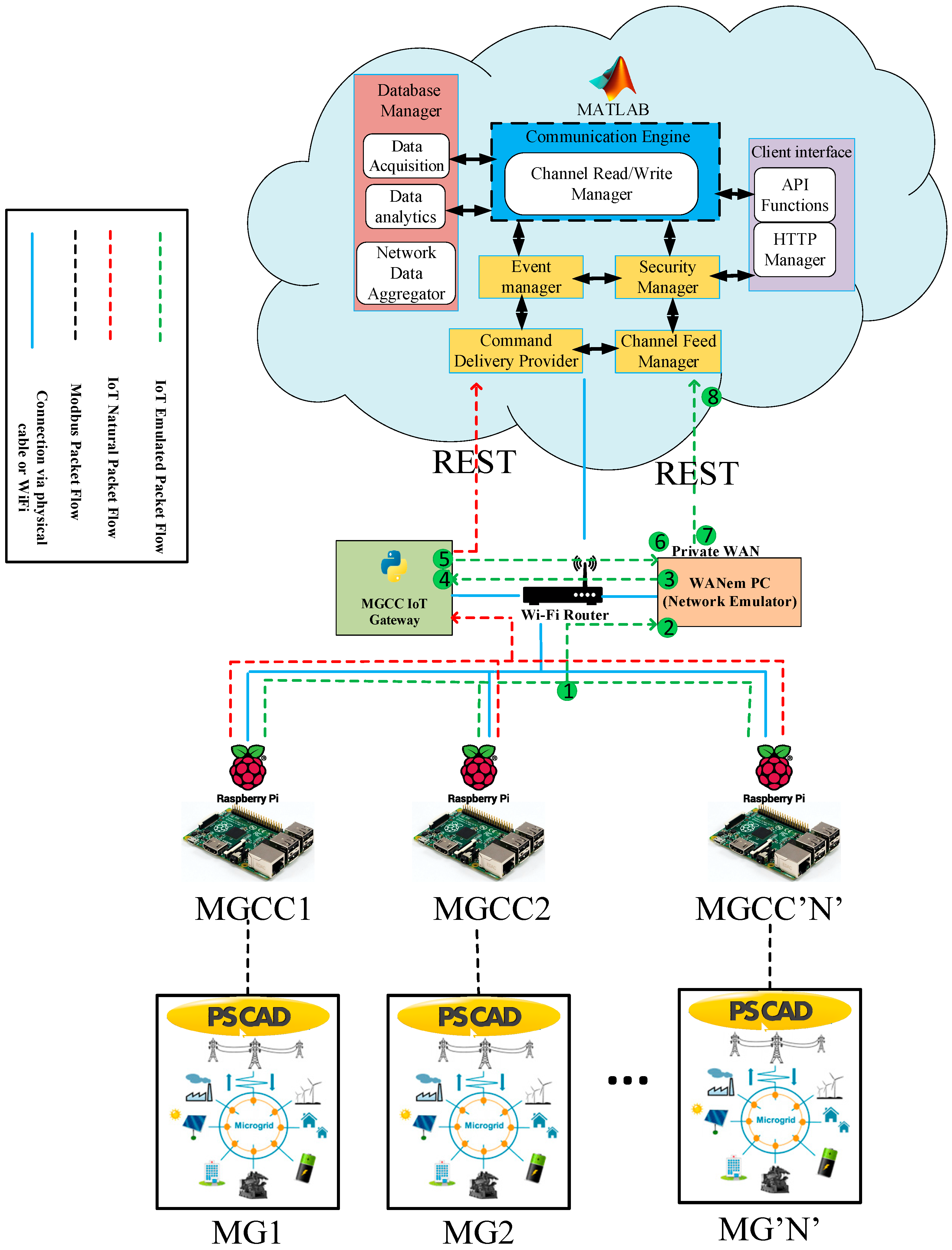
MG central controller (MGCC) receives data from IEDs and updates a cloud channel allocated to that particular MG. There is a specific MQTT topic dedicated to each MGCC to enable traceability of the updated data. The interactions between MGCC and the cloud server are implemented in a bi-directional fashion as seen in Figure 5. Hence, the results of the MMG dynamic NCC algorithm, which runs in the MATLAB interface, are subscribed by each MG controller and passed to the corresponding MG to be actuated.
Among various commercial cloud servers, ThingSpeak [25], which facilitates hardware integration with Raspberry Pi and Arduino Uno with its user-friendly Application Programming Interface (API) functions and easy-to-implement interface to MATLAB, is employed in this work. MATLAB ThingSpeak toolbox is used to retrieve the cloud data and run the dynamic NCC algorithm. There is a built-in interface in the cloud platform utilized in this work, which facilitates computational tasks on the collected data in the cloud channel. Hence, MATLAB is chosen in this research work.

4.2.3. Network Emulation in the Platform

Network latency is a major concern in MMG communications with large-scaled number of MGs, which exchange information at the same time. In MMG, there are multiple devices in each MG for local/global measurements, control and protection each capable of communication via a local/wide area network. Each device sends several messages to exchange information including measurements and control signals (Boolean and Float datatype). In extreme cases, with assumption of each device sending an average of 100 messages per second, it can lead to 1000–5000 ms packet delay and up to 10 million messages per second [26]. Due to this issue in the network, centralized operation of MMG, which requires data from all nodes in MMG, could be affected. Hence, the proposed platform is equipped with a virtual Wide Area Network emulator (WANem) machine, which aims to mimic realistic behaviour of a network. Network emulation is the act of altering the route of the packet flow to add a user-defined latency between the source and the destination of the network messages. As exhibited in Figure 5, network emulation is introducing a new device to a test network (could be LAN or WAN) to manually add delay, packet loss, jitter and distribution characteristics by WANem. The goal of having network emulator in the platform is to add packet delays, which is closer to the real-world communication networks in MMG environments with extensive number of devices and messages. MGs are simulated in PSCAD® software (PSCAD, Winnipeg, MB, Canada) [18], which communicates via Modbus protocol to MGCC to exchange data required for dynamic NCC algorithm. A Raspberry Pi as a middle player between PSCAD® and the cloud server incorporates MGCC of each MG. The hardware setup in the proposed platform is based on the cloud-integrity criteria. The cloud services utilized in this work are highly compatible with Raspberry Pi. Built-in features for read/write data from/on cloud channels are simply provided with minimum effort for external hardware configuration. In addition, current reliable operation of Raspberry Pi in industrial projects along with a reasonable market price for such microcomputers are other reasons for choosing Raspberry Pi.
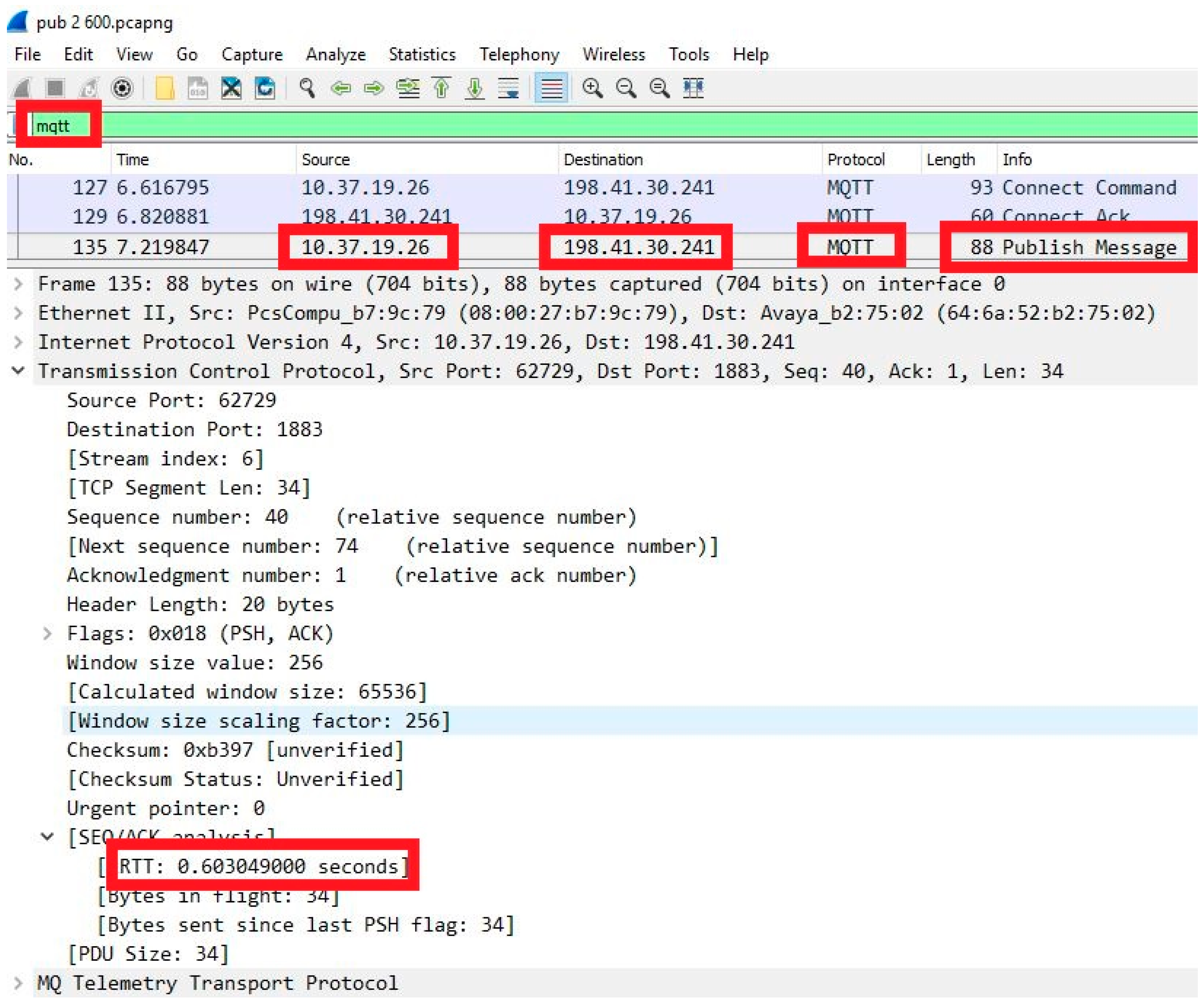
Red dotted line in Figure 5 represents the normal MMG packet flow in the network. Cloud channels allocated to each MG are updated with the input data to dynamic NCC algorithm by each MGCC. Green dotted line displays the packet flow path after adding the virtual WANem. WANem is an extra network component to alter the normal route of the data packet flow in the network in order to mimic realistic network behaviours by adding latency to the network. Emulated packet flow is marked by numbers from 1 to 8. Data packets published by each MGCC in each MG are not passed to the cloud directly; but the WANem machine receives them to incorporate the user-defined packet delays. If the allocated cloud channels do not receive data packets within 300 milliseconds, it means cloud failure has happened. There are two main layers of communications in the proposed IoT platform each utilizing a security mechanism to make the platform reliable and secure. The first layer, which uses REST HTTP for cloud interactions, uses the very well-known TLS for offering provisions for data encryption and a secure communication channel. This is achieved by exchange of a shared secret key between the client and server within a TLS hand-shaking process. The second layer of communications based on MQTT protocol is secured by authentication implemented by MQTT brokers. There is an initialization process for establishing a connection between an MQTT client and an MQTT broker. This includes the three-step hand shaking process with exchanging control packets between the client and broker.

5. Communication System Operation Algorithm

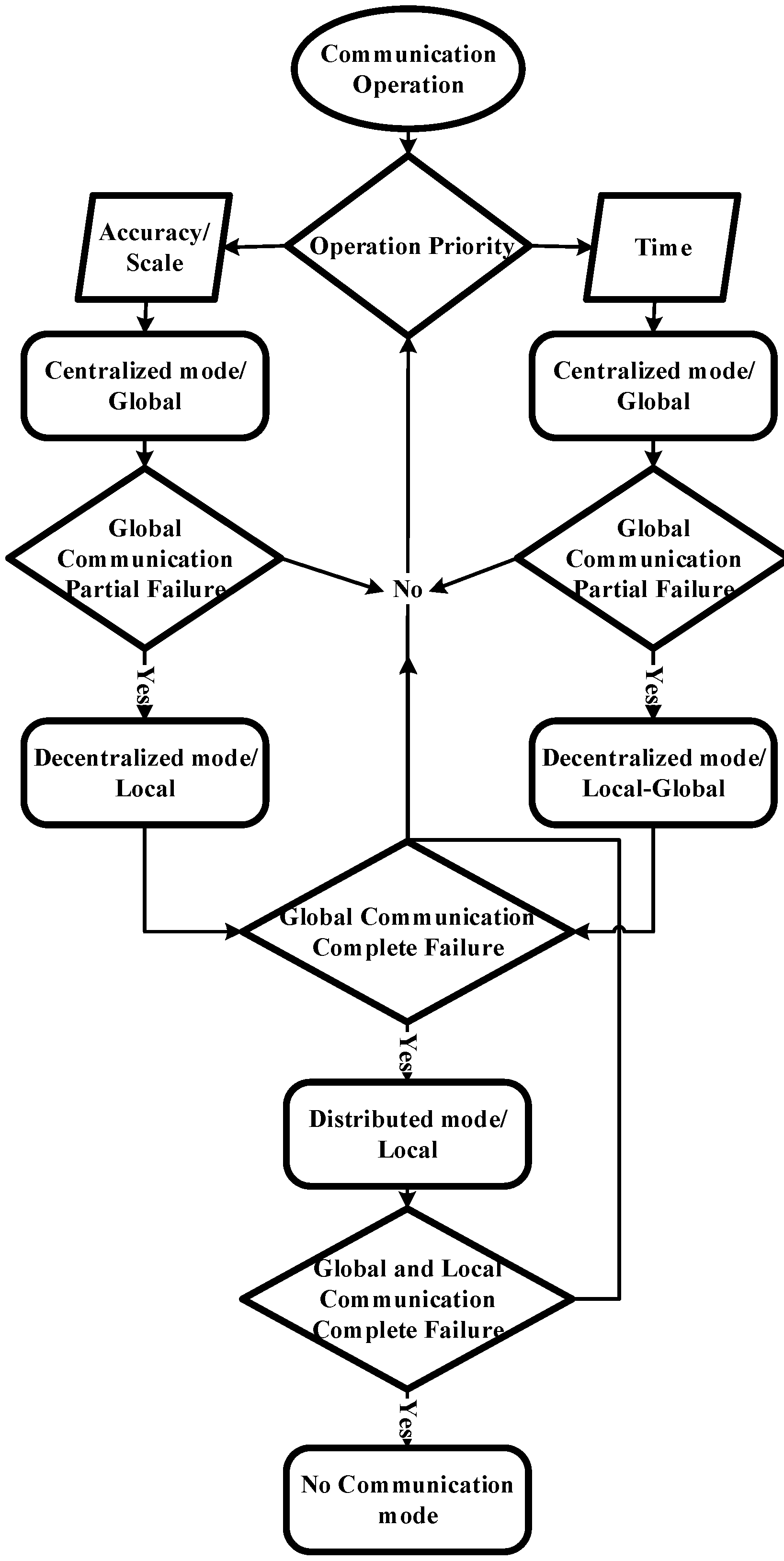
The communication system is capable of operating in different conditions. In case of communication failure, the communication operation algorithm rectifies the problem by changing the operation mode. Depending on the priority, Time and Accuracy/Scale in this study, the algorithm chooses the operation priority. After defining the operation priority, based on the level of the communication latency thresholds defined for network nodes, the appropriate communication operation mode is assigned.
Time operation priority means it is more important to get the data as soon as possible rather than how accurate or comprehensive the data package is. On the other hand, if Accuracy/Scale operation priority is chosen, it means the time it takes to get the data is not as vital as the accuracy and amount of the data taken for further analysis and decision-making. The communication operation algorithm is presented in Figure 6.
The communication algorithm follows a ruleset to change the operation mode. Table 1 describes the ruleset when the operation mode changes depending on communication delay. In this ruleset, the value of the round-trip time (RTT) defines in which mode the system is operating.

5.1. Centralized Communication Mode

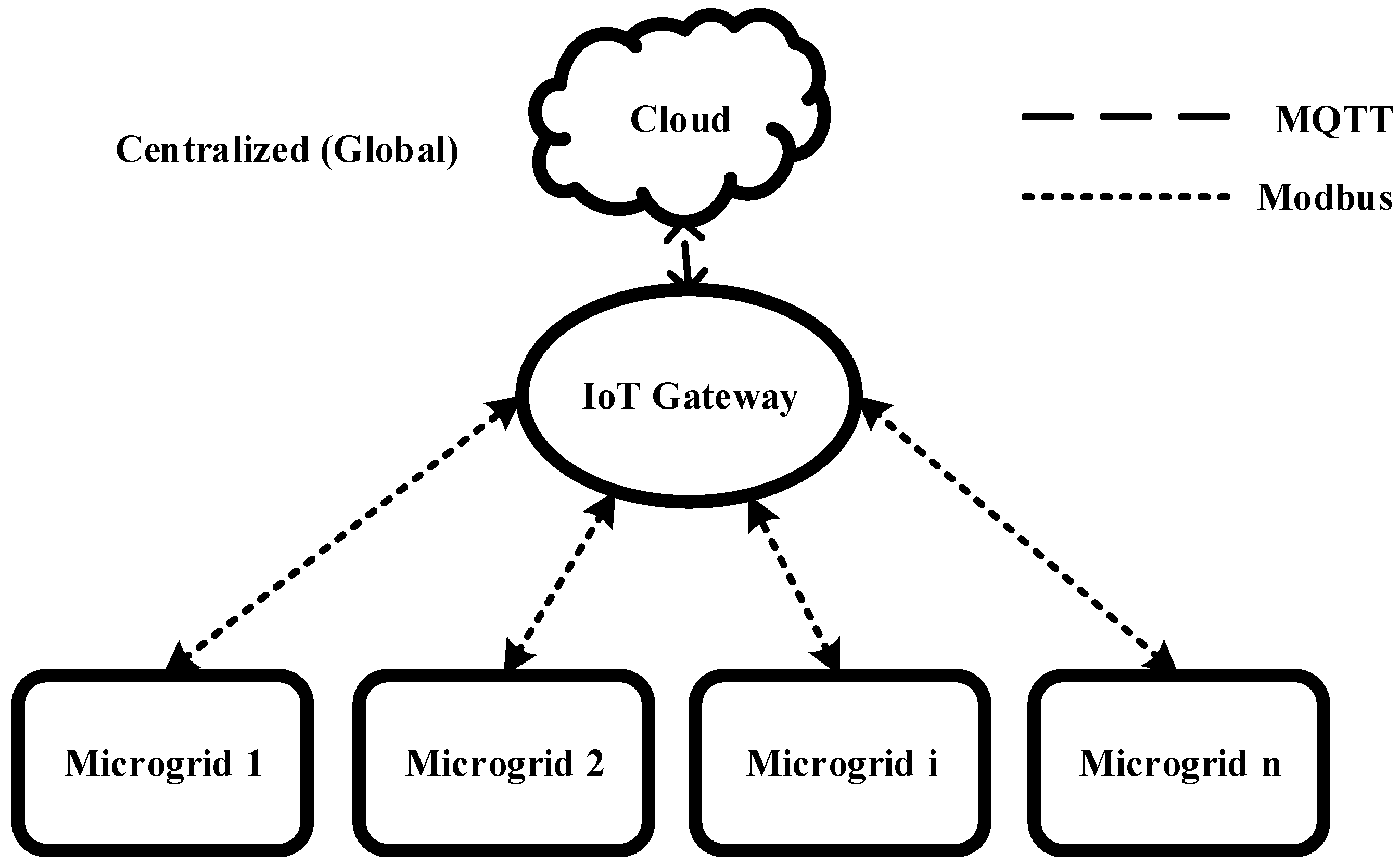
The centralized communication system structure is shown in Figure 7. As seen in this figure, each MG is connected to the IoT gateway and shares its data with other MGs through the cloud. In this communication operation mode, Modbus TCP/IP connects the MGs to the MGCCs and MQTT makes the connection between MGCCs and IoT gateway and the cloud. Comparing the communication operation modes, the centralized has the highest speed for data transfer and the highest decision accuracy (highest data scale).

5.2. Decentralized Communication Mode

In the condition of cloud communication partial failure (if 250   ms < R T T < 350   ms ), the communication operation mode would be set to the decentralized as presented in Figure 8. In this mode, not all the MGs are connected to the cloud but the main local MGs, m MGs ( m < n ). n is total number of MGs. Depending on the operation priority, either local or local-global mode is operating.

5.2.1. Local–Global

In the decentralized/local-global communication mode, the priority of accuracy/scale is higher than time. The data from the MGs surrounding the main m MGs are collected via Modbus TCP/IP and transferred from the m MGs to cloud via MQTT. In this case, it takes longer time compared to global to transfer data.

5.2.2. Global

In this operation mode, the priority of time is higher than accuracy/scale. The data from the MGs surrounding the m main MGs are not transferred, which means Modbus TCP/IP is not utilized in this mode and only the main m MGs transfer data via MQTT. In this case, each of the m MGs represent the MGs connected to them locally.

5.3. Distributed Communication Mode

In the communication operation algorithm, the condition that cloud fails is predicted via the distribution operation mode. In this operation mode, the connection to the cloud fails completely ( 350   ms < R T T < 500   ms ) and Modbus TCP/IP gets active. In this case, MGs are connected to each other via Modbus TCP/IP to transfer the required information. This mode of operation would give accurate information but it is slower than centralized and decentralized operation modes. The distributed communication mode is illustrated in Figure 9.

5.4. No Communication Mode

If the global and local communication levels fail (i.e., both MQTT and Modbus TCP/IP fail communicating), the operation mode of the MMG changes to no communication mode. This operation mode happens when R T T 500   ms . In the no communication mode, MGs are not exchanging any information and work based on their own local MGCC. In the case of dynamic NCC algorithm, step 8 gets inactive. This communication mode is shown in Figure 10.

6. Results

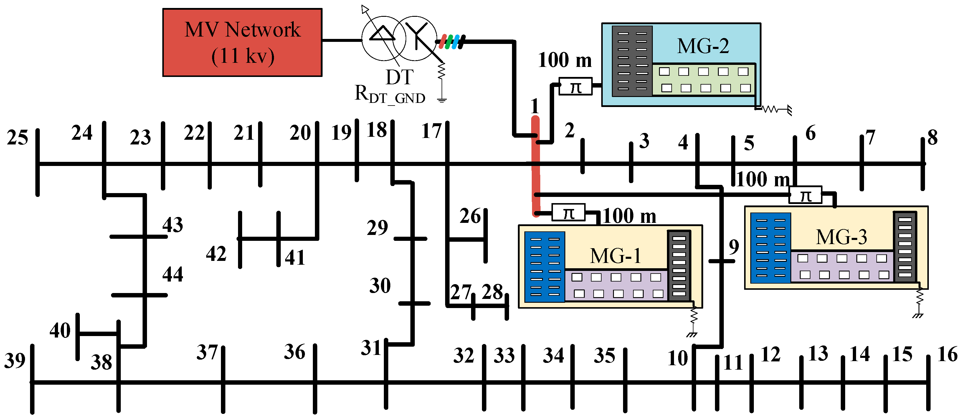
A 3P-4W 44-bus LV distribution network is utilized for the control and communication algorithm simulation and performance evaluation. Three commercial buildings are considered as the loads for the MGs to test the proposed system. The PV and commercial building load data is extracted from Griffith University monitoring system [19]. The representation of the LV network is depicted in Figure 11.
Due to various inductive loads in these buildings, there is high neutral current and phase unbalance to compensate as shown in Figure 12. Therefore, the VSIs are used to compensate for the neutral current in each MG and in the MMG. The load phase and neutral current as well as the performance of proposed system are studied for duration of one day.
As the focus is on the performance of the communication operation algorithm in different modes on the neutral current compensation, two main simulation scenarios are considered in this research. In Section 6.1, the operation of the MMG control system under the hierarchical communication system is observed, where the communication system is operating in centralized mode and it is assumed no effective delay has happened. To do so, different case scenarios are proposed to investigate the fixed and dynamic NCC sharing in MMG. In Section 6.2, the effect of communication delay on NCC is investigated. Three case scenarios are introduced to examine the performance of the communication operation algorithm in case of communication failure, where the communication system operates in different modes considering the operation algorithm and delays.

6.1. MMG Control System Performance Under the Hierarchical Communication System

The performance of the dynamic NCC algorithm for MG and MMG system with different case scenarios is explored as indicated in Table 2. The three case scenarios are introduced to examine if PV-VSI system is capable of compensating for neutral current in each MG and MMG (case Aa & case Ab) and dynamic NCC via data sharing for MMG (case Ac). In case Aa, the performance of the two NCC methods for each MG is investigated. On the other hand, to investigate the operation of the MMG dynamic NCC algorithm, case Ab and case Ac are compared against each other to inspect if MGs compensate the neutral current + sharing information in case that one of the MGs changes its control from dynamic to fixed NCC (MG1).
Figure 13a illustrates the performance of MG1 control system under case Aa and case Ab. It is seen that the dynamic NCC algorithm has a higher compensation than fixed neutral current approach for MG1. Furthermore, it is proved that excess PV capacity leads to more NCC using dynamic compensation method as in Figure 13b. During the PV generation period, MG3 has better current compensation with increase in PV generation as expected.
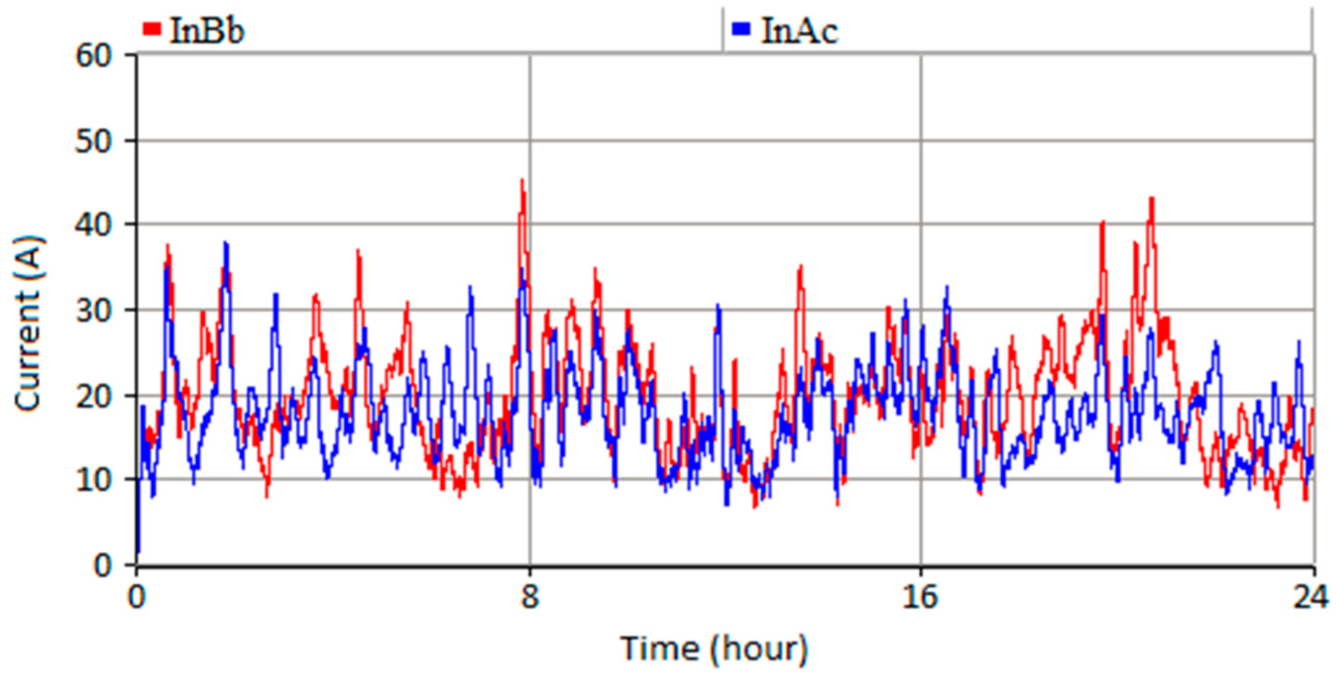
To observe the performance of the MMG dynamic NCC + sharing operation, case Ab and case Ac are compared. To do so, the dynamic NCC method in MG1 is changed from dynamic to fixed to limit NCC of MG1 and investigate its effect on neutral current level of MG2 and MG3. As seen in Figure 13a,b, MG2 and MG3 compensate to a higher extent in case Ac than case Ab. The MMG dynamic NCC + sharing algorithm uses the communication system (no delay in this case) to overcome the limitation of MG1 by compensating more neutral current via MG2 and MG3. The neutral currents shown in Figure 14 are the neutral currents from the grid side. Both the MG2 and MG3 compensate the neutral current to reduce the grid neutral current in the power lines. The red line is often higher than the blue line, which means the power line neutral current in case Ab is always higher than in case Ac. Therefore, in case Ac, the neutral current is compensated to a higher extent and more neutral current is compensated by the MGs.
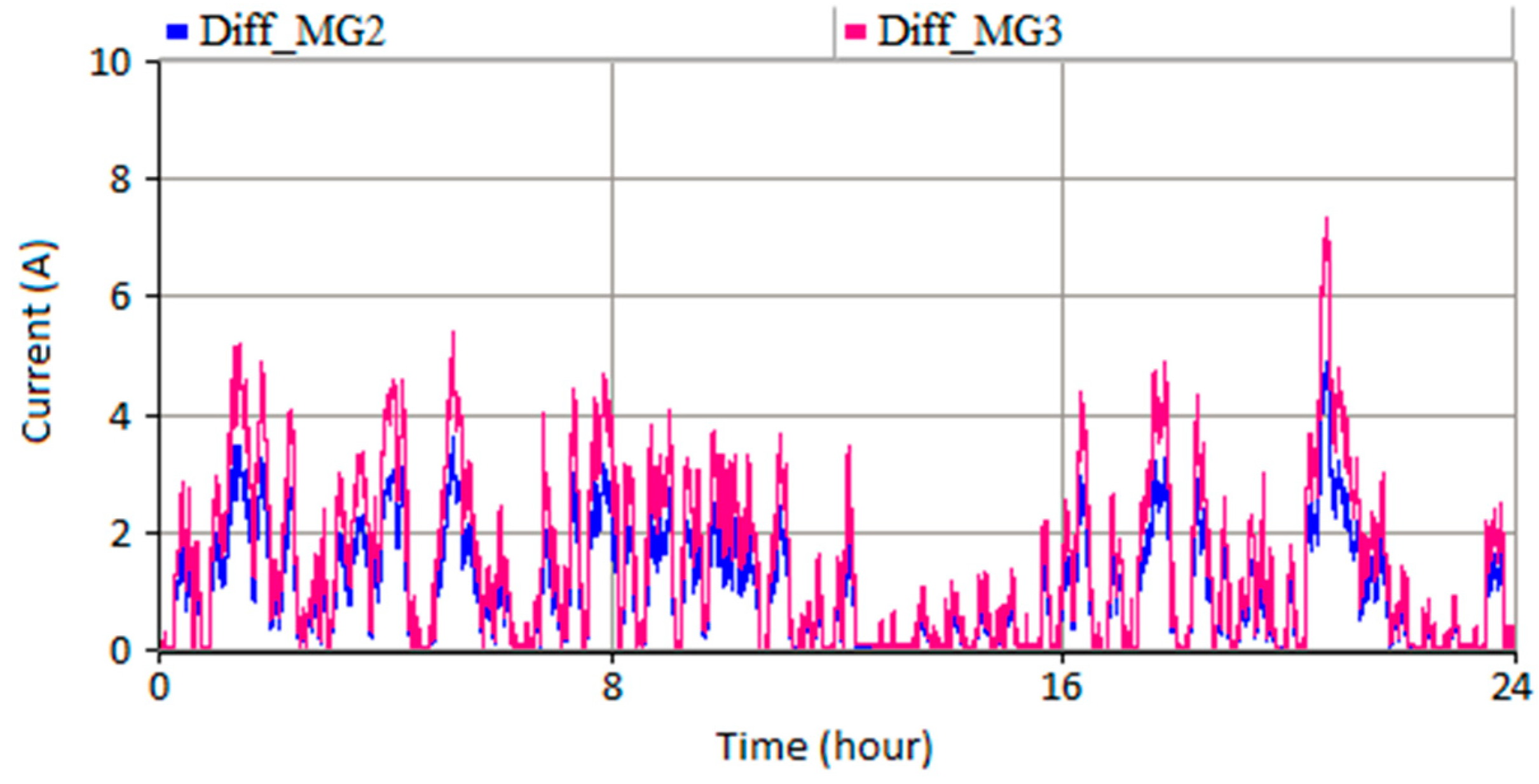
To look more precisely into the MMG dynamic NCC algorithm, the neutral current difference for MG2 and MG3 in case of NCC and NCC + sharing is shown in Figure 15. The MGs in the MMG manage the neutral current in communication with other MGs. The communication system transfers the data between the MGs employing the centralized communication system. As observed in Figure 15, in case b, the neutral current is limited and MG2 and MG3 increase their neutral current share to compensate for the neutral current following Equation (18).
To investigate the influence of the dynamic NCC + sharing algorithm on grid unbalance, the current unbalance factor (CUF) is compared for three cases in Figure 16. From case Aa to case Ab, the CUF has decreased (1.3% average). The reduction is due to shift from fixed compensation to dynamic compensation (MG1) and rise of PV generation (MG3). On the other hand, from case Ab to case Ac, the CUF is almost the same. It shows that despite limiting NCC of MG1 to fixed 10 A, MG2 and MG3 communicate and compensate the neutral current at PCC.

6.2. Effect of Communication Delay on NCC

In Section 6.1, the operation of the MMG control system is observed under centralized mode as the default communication mode, where the level of the communication delay is lower than effecting the performance of the control system. In this section, three case scenarios are introduced to investigate the performance of the communication operation algorithm in case of communication failure. In these scenarios, the control system sends the command to change the NCC from fixed to dynamic under communication delays. The scenarios are listed in Table 3. To implement the communication delays, WANem machine and Wireshark are employed to emulate the network delays and capture data packets as presented in Figure 17.

6.2.1. Case Ba: 250 ms ≤ Communication Delay < 350 ms

In this scenario, the cloud network partially fails. According to the ruleset in Table 1 and considering the communication operation algorithm, the mode of communication system changes from centralized into decentralized. In this mode, depending on the priority, algorithm gives the priority to accuracy or time. MG1 is experiencing RTT of 307 ms for data transfer. Therefore, it is disconnected from the cloud but still communicates to MG2 via Modbus TCP/IP. MG2 and MG3 are connected to the cloud and do not have communication delay. The communication delay implementation is presented in Figure 18.
(a) Time Priority
In the case of time priority, MG2 sets its own reference for MG1 regardless of data from MG1. MG3 sends its reference to the cloud directly. The NCC result is shown in Figure 19 compared to case Ac. The neutral current level has slightly increased under communication delay (3 A higher in average).
(b) Accuracy Priority
In this case, MG2 sends the data to the cloud after it receives all the information from MG1 via Modbus TCP/IP. Thus, it takes longer for the MGCCs to make decisions. The NCC result shown in Figure 20 reveals the fact that the level of neutral current is higher than the time priority case (2 A higher neutral current level).

6.2.2. Case Bb: 350 ms ≤ Communication Delay < 500 ms

If communication delay exceeds 350 ms, it means the decentralized system is not functional anymore (cloud has totally failed). Thus, communication operation algorithm changes to distributed mode. In the distributed mode, the communication system works locally and Modbus TCP/IP connects the MGs to each other. Modbus TCP/IP shares the data between MGs with a lower speed and capacity compared to MQTT. Furthermore, it takes longer for the MGCCs to make decisions due to the nature of distributed mode operation. The neutral current level is expected to rise compared to previous cases. The communication delay implementation for case Bb and the neutral current level is observed in Figure 21 and Figure 22 (7 A higher average neutral current level compared to case Ac).

6.2.3. Case Bc: Communication Delay ≥ 500 ms

The communication system operates to the extent that delay does not affect the data transfer severely. In this study, if the communication delay exceeds 500 ms, the communication operation system fails and enters into the no communication mode. In this mode, the MGs are not transferring data to each other and work based on the predefined references. The communication delay implementation is illustrated in Figure 23. As the neutral current reference is fixed by default, the NCC is expected to be worse compared to other cases. The result in Figure 24 indicates the lowest NCC among the studied cases (11 A in average higher than case Ac).

7. Discussion

The performance of the MMG control and communication system under various operation modes is investigated. Dynamic NCC approach shows higher capability to compensate for higher neutral current levels compared to fixed NCC. This is due to employing the excess power after active and reactive power operation for NCC instead of setting a fixed limit for NCC. The other variable which its effect is examined, is PV capacity rise in PV-VSI system. It is proven that extra PV generation can lead to higher NCC under the dynamic NCC approach.
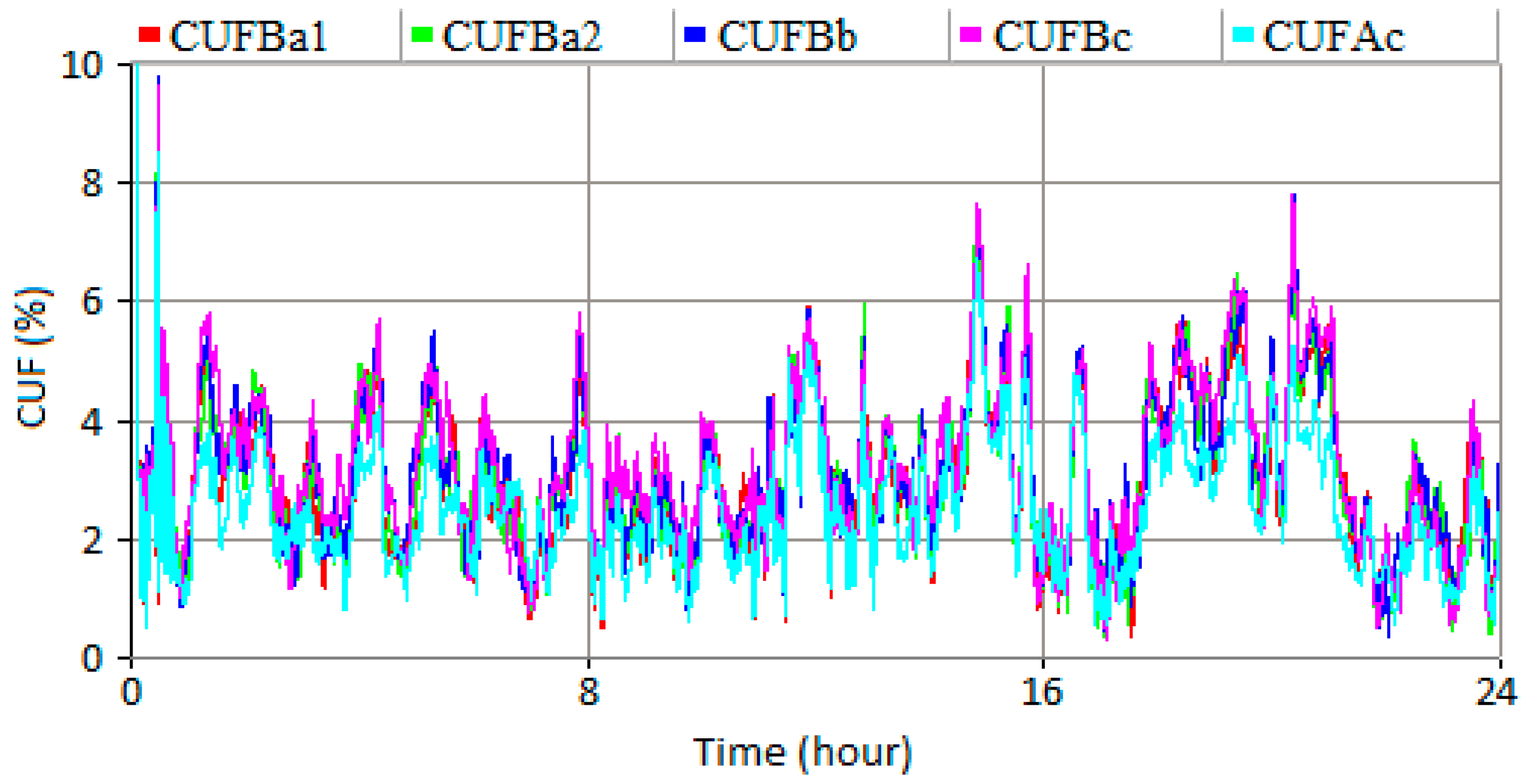
The other variable that affects the MMG dynamic NCC is the proposed dynamic NCC + sharing method. Utilizing this method has illustrated that MGs can compensate for neutral current of other MGs by communicating to each other. It is proven that the performance of the MMG dynamic NCC + sharing approach is dependent on the communication system. The operation of the communication system under different conditions is explored. Comparing the communication modes, the MMG dynamic NCC + sharing under centralized mode, where the impact of communication delays on the control system performance is negligible, shows highest potential for NCC and phase unbalance compensation. The CUF of MMG for different communication modes is compared in Figure 25. It shows that as the communication delay increases, the CUF increases as well, which means lower unbalance compensation.
In the case of distributed communication mode, the reason for weak performance of control system is limitation of Modbus TCP/IP. Modbus communication protocol is suitable for control applications that have a simple structure and transfer low amount of data. It is expected that utilizing MQTT instead of Modbus in the local communication level increase the performance of distributed operation mode.
The communication system is aiming to assist the better neutral compensation. However, the communication algorithm performance is not discussed due to its complexity. Problems within communication such as the latency and accuracy may also show an impact on the system’s performance, which shall be the next direction of this research. On the other hand, the MMG performance investigation within this article is based on the grid-tied mode. The islanding situation will introduce more challenging issues, which can be tackled through employing proper control methods in the future.

8. Conclusions

In this paper, a dynamic NCC approach in MMG system employing IoT platform is proposed. In order to investigate the neutral current compensation performance of the proposed control system, the MMG system under study as a part of a distribution network is implemented in PSCAD. The neutral current from the grid side can be significantly reduced under the proposed control method compared to the control method with fixed current limitation. In addition, to investigate the functionality of the IoT platform in control system operation, a two-level communication system connecting the PSCAD model to the cloud server is implemented. The local communication level uses Modbus TCP/IP and MQTT is utilized as the global communication protocol. It is shown that the MMG dynamic NCC + sharing method decreases the neutral current level and improves the phase unbalance. Furthermore, the communication system enhances the functionality of the MMG dynamic NCC method under different modes of operation. The effect of the communication delay is analysed in detail according to the simulation.

Author Contributions

Conceptualization, M.M., F.H.M.R. and P.J.; methodology, M.M., J.L. (Junwei Lu), F.H.M.R. and P.J.; software, M.M., P.J. and J.L. (Junwei Lu); validation, M.M., J.L. (Jiannan Liu) and P.J.; formal analysis, P.J. and J.L. (Junwei Lu); investigation, M.M., P.J. and J.L. (Junwei Lu); resources, M.M. and F.H.M.R.; data curation, J.L. (Jiannan Liu) and P.J.; writing—original draft preparation, M.M.; writing—review and editing, M.M.; visualization, M.M., J.L. (Jiannan Liu) and P.J.; supervision, J.H., S.S., J.L. (Junwei Lu) and S.R.; project administration, J.L. (Jiannan Liu), S.S., J.H. and S.R.; funding acquisition, S.R., J.H. and J.L. (Junwei Lu).

Funding

This research received no external funding.

Conflicts of Interest

The authors declare no conflict of interest.

References

  1. Patel, S.; Hmurcik, L. Preventable ground wire accidents and fires. In Proceedings of the 2016 IEEE 16th International Conference on Environment and Electrical Engineering (EEEIC), Florence, Italy, 7–10 June 2016. [Google Scholar]
  2. Ijjada, D.; Agarwal, P.; Das, B. Neutral current compensation in three-phase, four-wire systems: A review. Electr. Power Syst. Res. 2012, 86, 170–180. [Google Scholar]
  3. Moghimi, M.; Rafi, F.H.; Jamborsalamati, P.; Liu, J.; Hossain, M.J.; Lu, J. Improved Unbalance Compensation for Energy Management in Multi-Microgrid System with Internet of Things Platform. In Proceedings of the 18th IEEE International Conference on Environment and Electrical Engineering (IEEE EEEIC18), Palermo, Italy, 12–15 June 2018. [Google Scholar]
  4. Pattnaik, M.; Kastha, D. Harmonic Compensation With Zero-Sequence Load Voltage Control in a Speed-Sensorless DFIG-Based Stand-Alone VSCF Generating System. IEEE Trans. Ind. Electron. 2013, 60, 5506–5514. [Google Scholar] [CrossRef]
  5. Alam, M.J.E.; Muttaqi, K.M.; Sutanto, D. Alleviation of Neutral-to-Ground Potential Rise Under Unbalanced Allocation of Rooftop PV Using Distributed Energy Storage. IEEE Trans. Sustain. Energy 2015, 6, 889–898. [Google Scholar] [CrossRef]
  6. Singh, M.; Khadkikar, V.; Chandra, A.; Varma, R.K. Grid Interconnection of Renewable Energy Sources at the Distribution Level With Power-Quality Improvement Features. IEEE Trans. Power Deliv. 2011, 26, 307–315. [Google Scholar] [CrossRef]
  7. Rafi, F.H.M.; Hossain, M.J.; Lu, J. Improved Neutral Current Compensation With a Four-Leg PV Smart VSI in a LV Residential Network. IEEE Trans. Power Deliv. 2017, 32, 2291–2302. [Google Scholar] [CrossRef]
  8. Guo, X.; He, R.; Jian, J.; Lu, Z.; Sun, X.; Guerrero, J.M. Leakage Current Elimination of Four-Leg Inverter for Transformerless Three-Phase PV Systems. IEEE Trans. Power Electron. 2016, 31, 1841–1846. [Google Scholar] [CrossRef] [Green Version]
  9. Hossain, J.; Rafi, F.; Town, G.; Lu, J. Multifunctional Three-Phase Four-Leg PV-SVSI with Dynamic Capacity Distribution Method. IEEE Trans. Ind. Inform. 2018, 14, 2507–2520. [Google Scholar] [CrossRef]
  10. Al-Saedi, W.; Lachowicz, S.W.; Habibi, D.; Bass, O. Power quality enhancement in autonomous microgrid operation using Particle Swarm Optimization. Int. J. Electr. Power Energy Syst. 2012, 42, 139–149. [Google Scholar] [CrossRef]
  11. Burgos-Mellado, C.; Hernández-Carimán, C.; Cárdenas, R.; Sáez, D.; Sumner, M.; Costabeber, A.; Paredes, H.K.M. Experimental Evaluation of a CPT-Based Four-Leg Active Power Compensator for Distributed Generation. IEEE J. Emerg. Sel. Top. Power Electron. 2017, 5, 747–759. [Google Scholar] [CrossRef] [Green Version]
  12. Lee, Y.T.; Hsiao, W.H.; Huang, C.M.; Chou, S.T. An integrated cloud-based smart home management system with community hierarchy. IEEE Trans. Consum. Electron. 2016, 62, 1–9. [Google Scholar] [CrossRef]
  13. Byun, J.; Hong, I.; Park, S. Intelligent cloud home energy management system using household appliance priority based scheduling based on prediction of renewable energy capability. IEEE Trans. Consum. Electron. 2012, 58, 1194–1201. [Google Scholar] [CrossRef]
  14. Chen, Y.; Chang, J.M. EMaaS: Cloud-Based Energy Management Service for Distributed Renewable Energy Integration. IEEE Trans. Smart Grid 2015, 6, 2816–2824. [Google Scholar] [CrossRef]
  15. Byun, J.; Kim, Y.; Hwang, Z.; Park, S. An intelligent cloud-based energy management system using machine to machine communications in future energy environments. In Proceedings of the 2012 IEEE International Conference on Consumer Electronics (ICCE), Las Vegas, NV, USA, 13–16 January 2012. [Google Scholar]
  16. Suciu, G.; Fratu, O.; Necula, L.; Pasat, A.; Suciu, V. Machine-to-Machine communications for Cloud-based energy management systems within SMEs. In Proceedings of the 2016 IEEE 22nd International Symposium for Design and Technology in Electronic Packaging (SIITME), Oradea, Romania, 20–23 October 2016. [Google Scholar]
  17. Jamborsalamati, P.; Fernandez, E.; Moghimi, M.; Hossain, M.J.; Heidari, A.; Lu, J. MQTT-Based Resource Allocation of Smart Buildings for Grid Demand Reduction Considering Unreliable Communication Links. IEEE Syst. J. 2018, 1–12. [Google Scholar] [CrossRef]
  18. Available online: https://hvdc.ca/knowledge-base/v: (accessed on 11 September 2018).
  19. Moghimi, M.; Bennett, C.; Leskarac, D.; Stegen, S.; Lu, J. Communication architecture and data acquisition for experimental MicroGrid installations. In Proceedings of the 2015 IEEE PES Asia-Pacific Power and Energy Engineering Conference (APPEEC), Brisbane, QLD, Australia, 15–18 November 2015. [Google Scholar]
  20. Available online: http://mqtt.org/ (accessed on 11 September 2018).
  21. Dizdarevic, J.; Carpio, F.; Jukan, A.; Masip-Bruin, X. Survey of communication protocols for Internet-of-Things and related challenges of fog and cloud computing integration. arXiv, 2018; arXiv:1804.01747. [Google Scholar]
  22. Modbus Messaging Implementation Guide Version1_0a. Available online: http://www.modbus.org/docs/Modbus_Messaging_Implementation_Guide_V1_0a.pdf (accessed on 11 September 2018).
  23. Guo, Y.; Pan, M.; Fang, Y.; Khargonekar, P.P. Decentralized Coordination of Energy Utilization for Residential Households in the Smart Grid. IEEE Trans. Smart Grid 2013, 4, 1341–1350. [Google Scholar] [CrossRef]
  24. Available online: http://www.eclipse.org/paho/ (accessed on 11 September 2018).
  25. Available online: http://thingspeak.com/ (accessed on 11 September 2018).
  26. Manbachi, M.; Sadu, A.; Farhangi, H.; Monti, A.; Palizban, A.; Ponci, F.; Arzanpour, S. Real-time communication platform for Smart Grid adaptive Volt-VAR Optimization of distribution networks. In Proceedings of the 2015 IEEE International Conference on Smart Energy Grid Engineering (SEGE), Oshawa, ON, Canada, 17–19 August 2015. [Google Scholar]
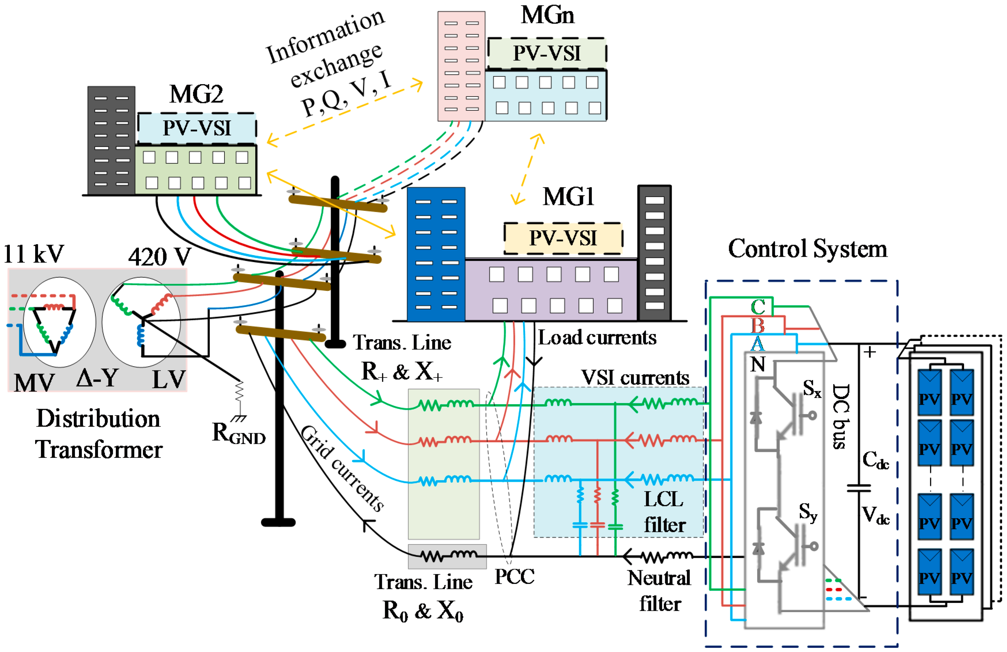
Figure 1. Multi-Microgrid (MMG) system architecture.
Energies 11 03102 g001
Figure 2. Unbalanced compensation system for Microgridi (MGi).
Energies 11 03102 g002
Figure 3. MMG dynamic Neutral Current Compensation (NCC) method.
Energies 11 03102 g003
Figure 4. MMG Internet of Things (IoT) platform.
Energies 11 03102 g004
Figure 5. Overview of the cloud-based MMG communication platform.
Energies 11 03102 g005
Figure 6. Proposed communication system operation algorithm.
Energies 11 03102 g006
Figure 7. Centralized communication mode.
Energies 11 03102 g007
Figure 8. Decentralized communication mode.
Energies 11 03102 g008
Figure 9. Distributed communication mode.
Energies 11 03102 g009
Figure 10. No communication mode.
Energies 11 03102 g010
Figure 11. 3-phase 4-wire 44-bus Low Voltage (LV) network including MMG system.
Energies 11 03102 g011
Figure 12. Phase neutral current and load neutral current of: (a) MG1; (b) MG2; (c) MG3.
Energies 11 03102 g012
Figure 13. MG dynamic compensation performance: (a) MG1; (b) MG3.
Energies 11 03102 g013
Figure 14. MGG dynamic NCC + sharing performance comparing case Ac and case Ab for: (a) MG2; (b) MG3.
Energies 11 03102 g014
Figure 15. Neutral current changes for MG2 and MG3 in case Ac and Ab.
Energies 11 03102 g015
Figure 16. Current Unbalance Factor (CUF) comparison at PCC for case Aa, Ab and Ac.
Energies 11 03102 g016
Figure 17. Communication delay implementation.
Energies 11 03102 g017
Figure 18. Communication delay implementation for case Ba.
Energies 11 03102 g018
Figure 19. NCC under communication delay for case Ba-Time against case Ac.
Energies 11 03102 g019
Figure 20. NCC under communication delay for case Ba-Accuracy against case Ac.
Energies 11 03102 g020
Figure 21. Communication delay implementation for case Bb.
Energies 11 03102 g021
Figure 22. NCC under communication delay for case Bb against case Ac.
Energies 11 03102 g022
Figure 23. Communication delay implementation for case Bc.
Energies 11 03102 g023
Figure 24. NCC under communication delay for case Bc against case Ac.
Energies 11 03102 g024
Figure 25. CUF comparison at PCC for cases Ac, Ba-Time, Ba-Accuracy, Bb and Bc.
Energies 11 03102 g025
Table 1. Ruleset for the communication system operation.
RTTCommunication Operation Mode
R T T < 250   ms centralized communication mode
250   ms R T T < 350   ms decentralized communication mode/global
250   ms R T T < 350   ms decentralized communication mode/local-global
350   ms R T T < 500   ms distributed communication mode
R T T 500   ms no communication mode
Table 2. Case scenarios for MMG control system performance.
ScenariosConfiguration of MGs
Case AaAa1. MG1 with 10 kW PV and 10A fixed neutral compensation
Aa2. MG2 with 10 kW PV and dynamic neutral compensation
Aa3. MG3 with 10 kW PV and dynamic neutral compensation
Case AbAb1. MG1 with 10 kW PV and dynamic neutral compensation
Ab2. MG2 with 10 kW PV and dynamic neutral compensation
Ab3. MG3 with 15 kW PV and dynamic neutral compensation
Case AcAc1. MG1 with 10 kW PV and 10 A fixed neutral compensation
Ac2. MG2 with 10 kW PV and dynamic NCC + sharing
Ac3. MG3 with 15 kW PV and dynamic NCC + sharing
Table 3. Case scenarios for communication system performance.
ScenariosCommunication Delay (CD)
Case Ba250 ms ≤ CD < 350 ms
Case Bb350 ms ≤ CD < 500 ms
Case BcCD ≥ 500 ms