1. Introduction
Wireless power transfer (WPT), because of its convenience, safety, flexibility, and some other advantages, has been extensively used in many fields such as mobile phones, biomedicines, smart homes, and communication [
1,
2,
3,
4]. In recent years, with the gradual growth of the global energy revolution, WPT technology has been progressively developing to high-power applications from the kilowatt to the megawatt power level. As an emerging technology, wireless charging for electric vehicles could solve the drawbacks of low battery capacity and time-consuming and labor-intensive plug-in charging [
5,
6,
7]. Considering the fact that high-speed train pantograph is easy to wear and produce electric arc, which leads to unreliable power supply, WPT used in high-speed rail is also a hot research topic [
8,
9]. Moreover, inductive power transfer for marine mechanisms such as ships could reduce the impact of extreme weather at sea and of limited berthing time [
10].
However, the coupling mechanism in WPT systems, owing to the existence of inductive current and time-varying electromagnetic fields, is inevitably affected by the electromagnetic force (EMF). With the increase of transmission power, the excitation current and space-coupling magnetic field will be increased. Thus, the EMF in high-power WPT systems has not to be ignored.
EMF has been researched by several methods in numerous fields [
11]. An improved superposition method was proposed to predict the unbalanced magnetic force of permanent magnet machines. In reference [
12], the cross-frequency of EMF in the induction heating application of a linear induction motor, which could improve the stability of the system, was investigated.
For WPT systems, a study [
13] proposed a type of micro-robot, which could transmit energy through a magnetic field, and the EMF on the receiving coil also provide a driving force to the robot. To precisely control turning and tracing of the robot, a study [
14] floated the receiving coil on water, and the characteristics of EMF were obtained by calculating the drift velocity of the coil. The authors assumed that the magnetic field was perpendicular to the receiving coil and only generated a tangential force on the coil.
However, the EMF of a high-power WPT system has rarely been analyzed. In practical applications, the magnetic field is alternating, which will generate EMF in various directions, and most of the EMF has negative effects rather than being a driving force [
15,
16]. Generally, EMF is the main inducer of a continuous periodic vibration causing the braking of the mechanism. Under the long-term action of the EMF, service life, security, and reliability of WPT system will deteriorate. In addition, the EMF also produces noise pollution in the surrounding environment [
17]. The characteristics of EMF on a ferromagnetic material in a WPT system were analyzed in reference [
18], which only considered the receiver and did not obtain exact conclusions on the effects of the EMF on the WPT system.
In this paper, on the basis of the high-power wireless power transfer system, detailed characteristics of the EMF on the coupling mechanism with magnetic shielding in WPT are revealed. The paper is organized as follows.
Section 2 will classify the EMF in a WPT system on the basis of the traditional Korteweg–Helmholtz force density method of EMF. In
Section 3, this paper will deduce the analytic expressions of the EMF on the coupling mechanism of a high-power WPT system and obtain the theoretical distribution characteristics and frequency characteristics of the EMF. At the same time, the magnitude of the EMF will be solved by means of the finite element method, and the correctness of the theoretical analytic results will also be verified by the simulation. In
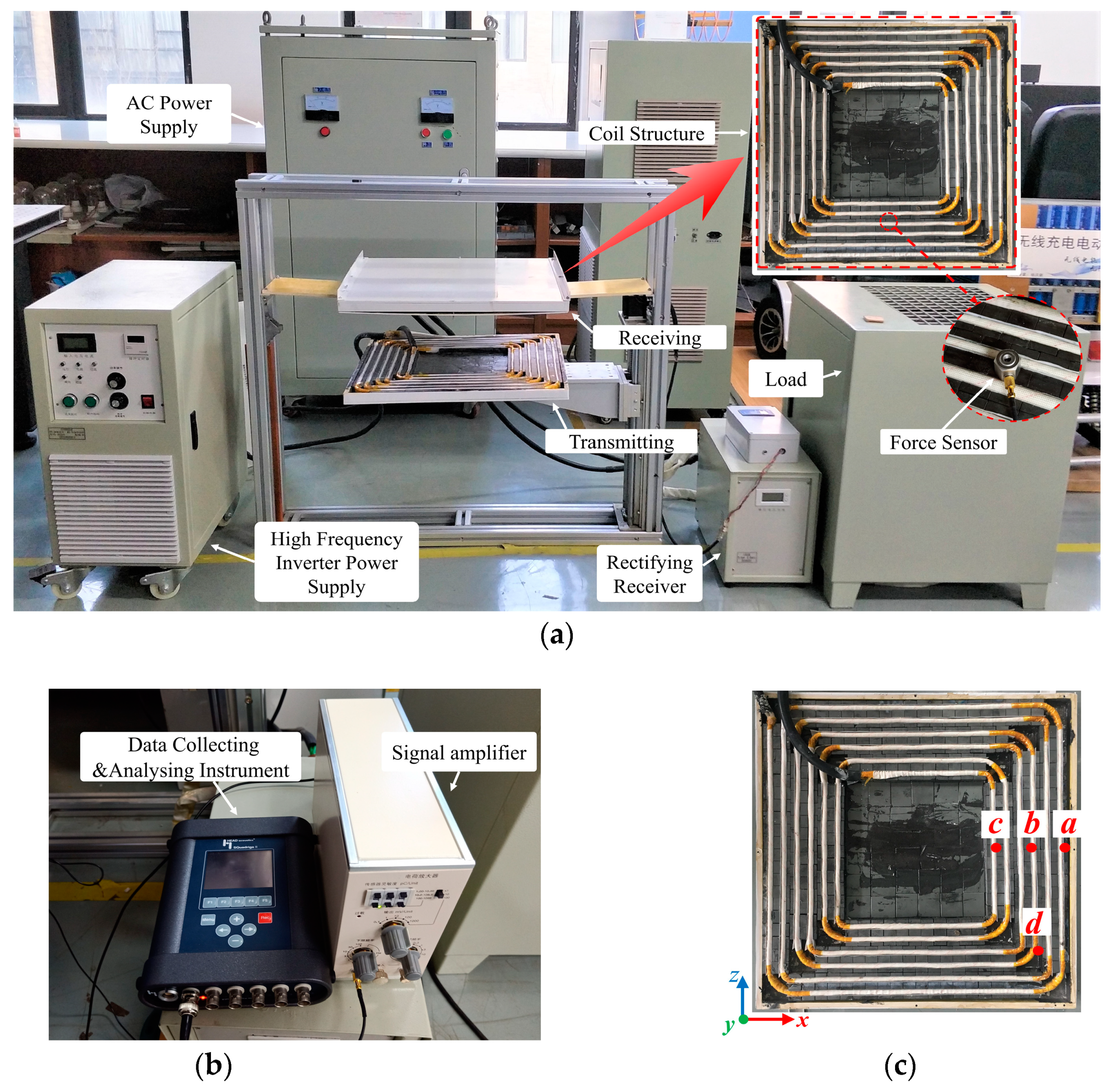
Section 4, an experimental prototype will be built to verify the correctness of the characteristics. Further, the change regulation of the EMF will be discussed.
Section 5 will draw conclusions about this paper.
2. Classification and Model of EMF in WPT
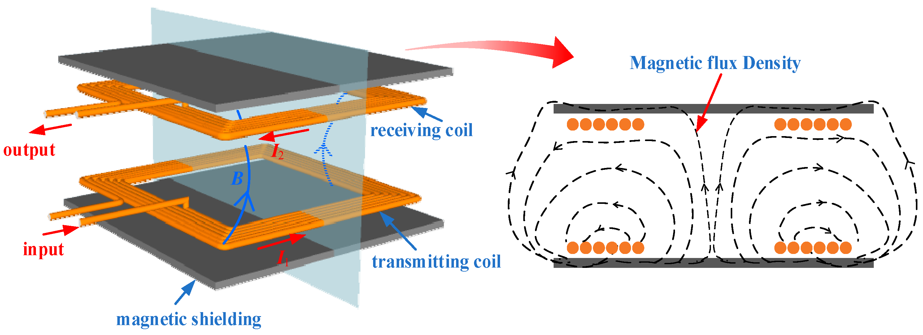
The structure of the commonly used coupling mechanism in a WPT system is presented in
Figure 1.
I1 is the exciting current of the transmitting coil (Tx-coil), generating magnetic flux density
B in the coupling domain. The magnetic field produces inductive current
I2 in the receiving coil (Rx-coil), which is rectified and inverted to supply load, delivering energy without any electrical connection. Considering the location in which the WPT system is installed in high-power applications, a square coil has been used to improve space utilization. The magnetic shielding is ferromagnetic material, added to optimize the distribution of the magnetic field and improve the transmission efficiency in the WPT system.
The exciting current of the WPT system is sinusoidal and alternating, thus the displacement current can be ignored, and the magnetic field generated by the coupling mechanism can be equivalent to the magnetoquasistatic field. Meanwhile, because the materials of WPT system are linear and incompressible, the Korteweg–Helmholtz force density method [
15] is used to investigate the characteristics of the EMF coupling coils and magnetic shielding materials, neglecting magnetostriction. The EMF density
f on the unit volume of the mechanism is expressed as:
where
J is the current density in the coils,
B refers to the magnetic flux density,
H denotes the magnetic field intensity,
μ is the permeability of the shielding. The relationship between
B and
H of magnetically linear materials is
.
It can be seen that the EMF in the WPT system consists of Lorentz force fJ and Kelvin force fM. fM is produced by the interaction between the magnetic field and the magnetizing current. The material of coupling coils in WPT is copper, whose permeability almost nears 1, so the coils cannot be magnetized but only subjected to Lorentz force fJ. Generally, magnetic shielding materials in WPT are linear soft magnetic materials, the conductivity of which is very small, and the eddy current of which can be ignored. Thus, Kelvin force fM is just acting on the magnetic shielding.
In order to study the characteristics of the EMF on the WPT mechanism, a finite element analysis model is built according to
Figure 1. The important parameters of the coupling mechanism are given in
Table 1. In order to reduce the alternating current (AC) resistance loss of the coils in the high-power system, a 10.89 kHz frequency is adopted. The transmission distance is set to 20 cm according to the actual electric vehicle or high-speed rail chassis height. The exciting current is adjustable for simulating the states of different output powers, with an initial value of 171.8 A.
3. Electromagnetic Force Calculation and Analysis
3.1. Current Calculation in WPT with Magnetic Shielding
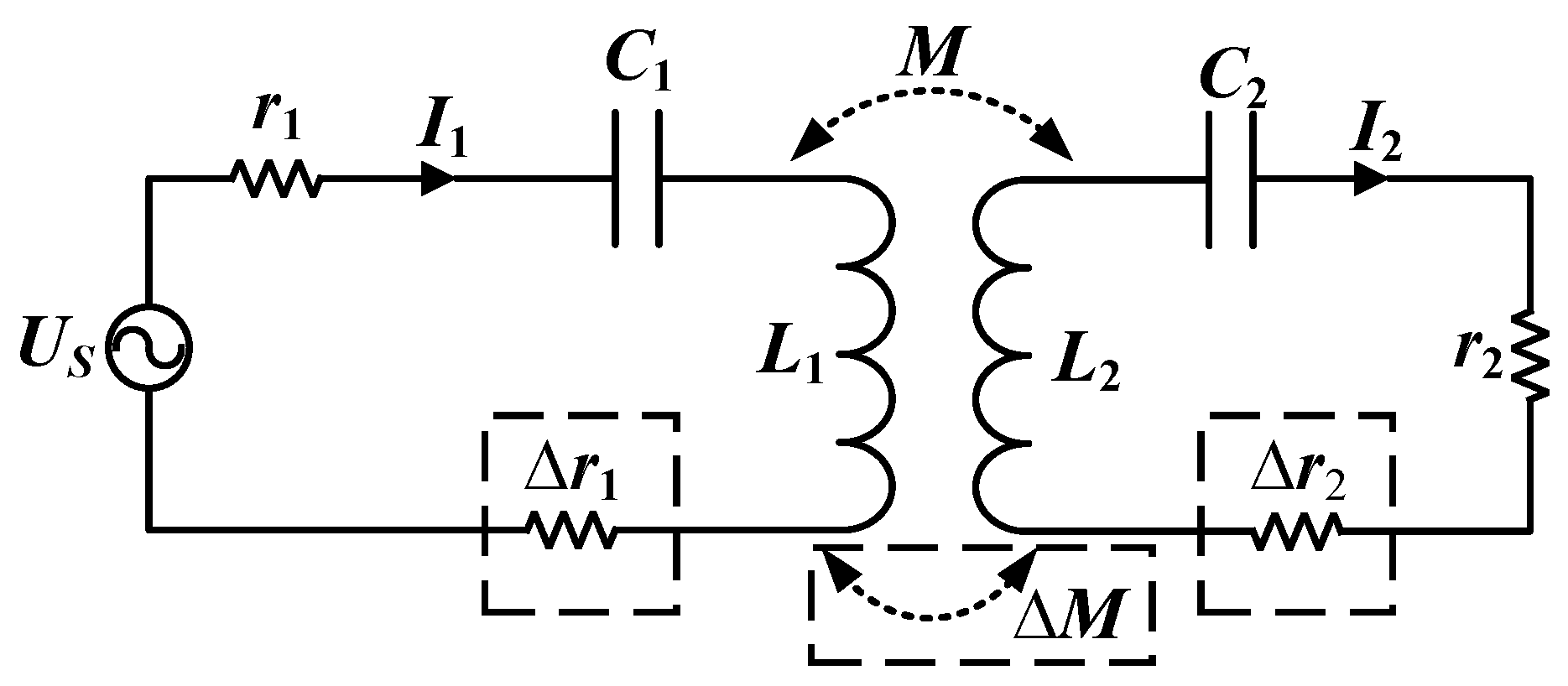
Figure 2 illustrates the most basic series–series compensated topology of the WPT system with magnetic shielding, in which
r1 is the sum of the resistances of the source
Us and the transmitting coil,
r2 is the sum of the resistances of the receiving coil and the load, and
L1 and
L2 represent the transmitting coil and the receiving coil, respectively.
M is the mutual inductance of the coils, and ∆
r1, ∆
r2, ∆
M are the additional resistances and mutual-inductance caused by the magnetic shielding, respectively. Because the resonant capacitors,
C1 and
C2, matched the inductance, making the system work at resonance frequency ω, the additional inductance is ignored. Equation (2) shows Kirchhoff’s voltage equation of the system.
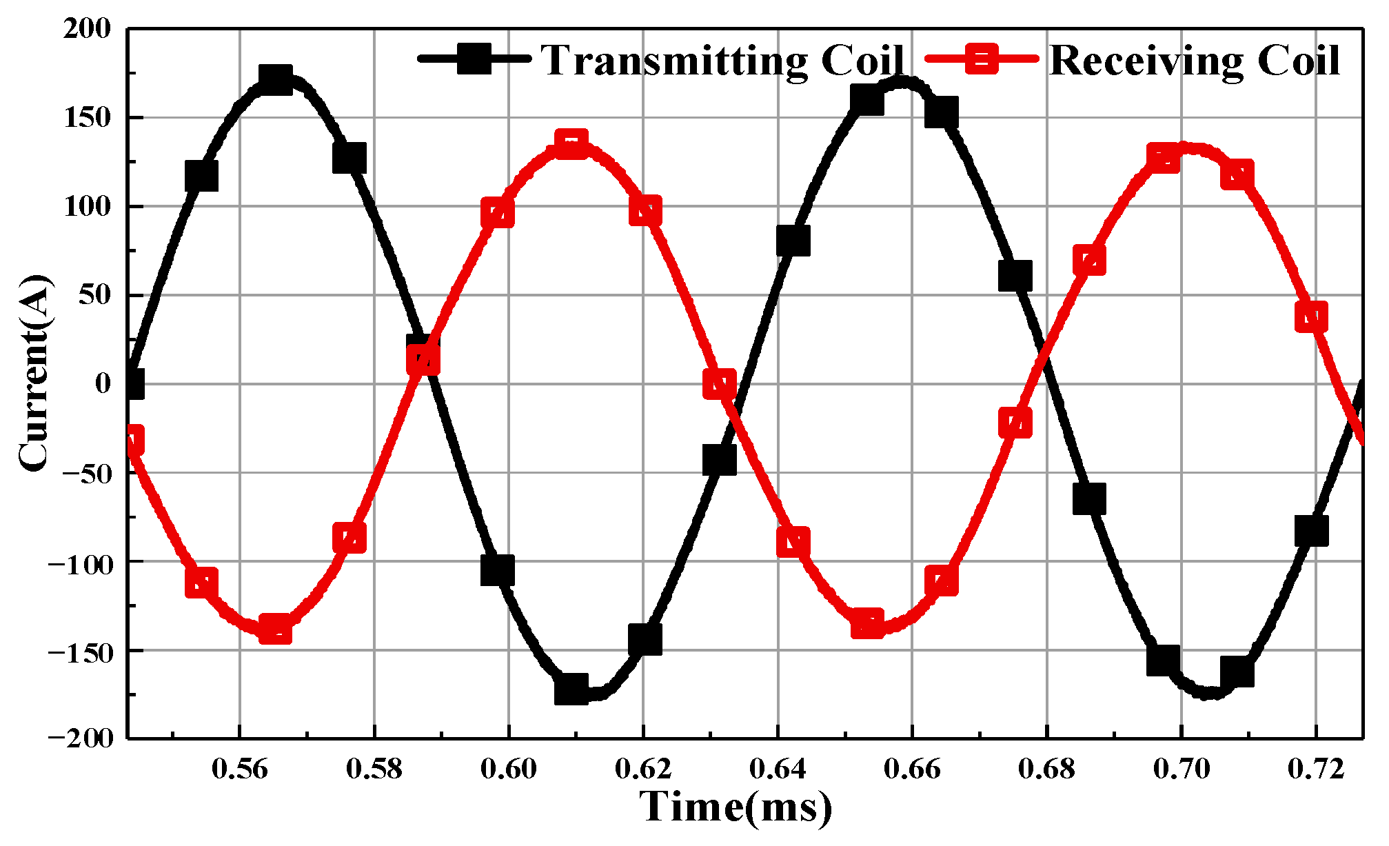
The exciting current
I1 and inductive current
I2 can be obtained, as shown in Equation (3). It can be shown that the amplitude of the currents is related to the increments of the resistances and mutual inductance, which depend on the shape and location of the magnetic shielding.
Figure 3 shows the currents of the coupling coils in the simulation.
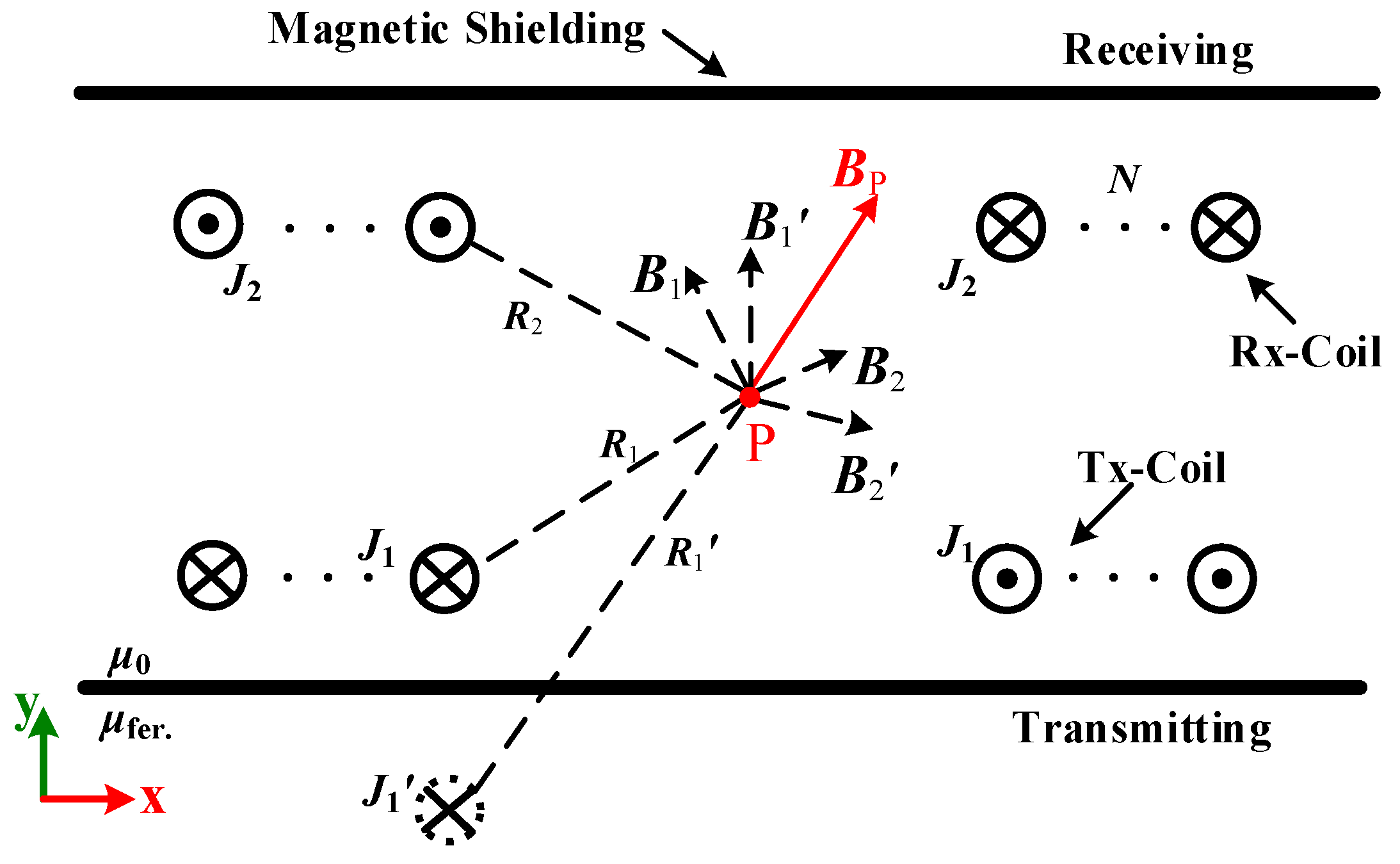
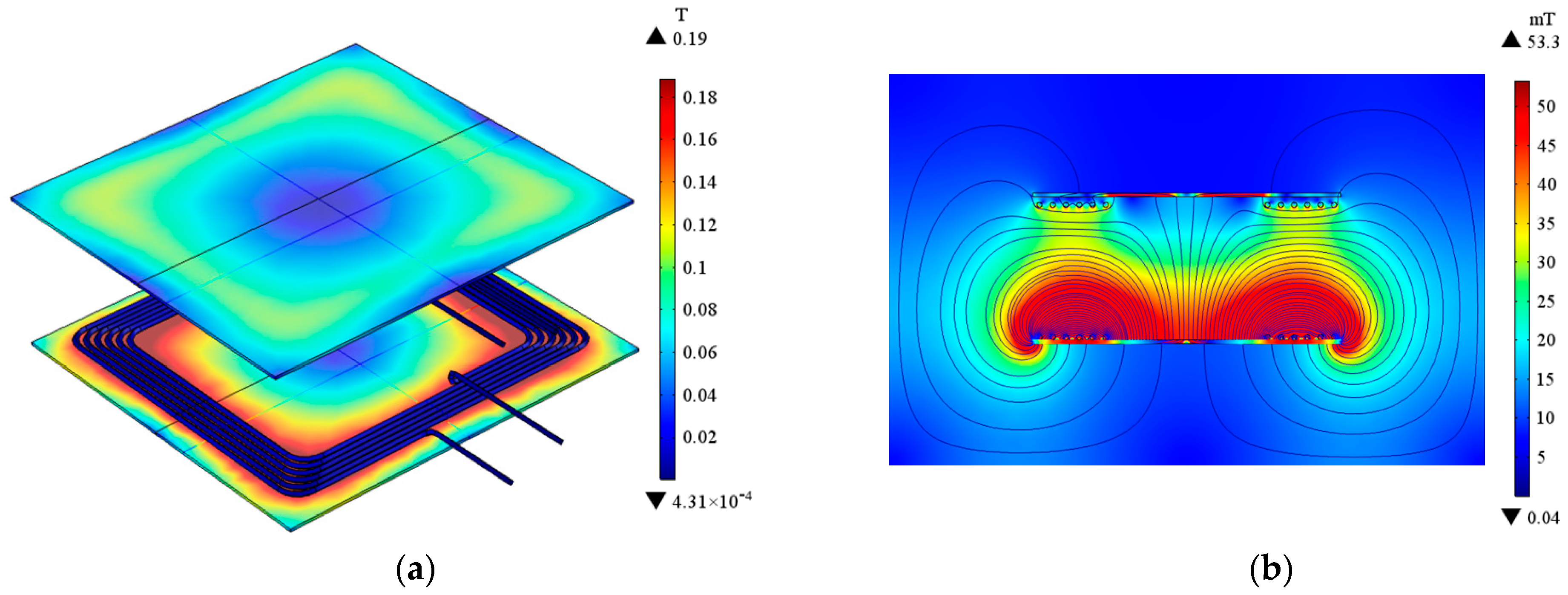
3.2. Magnetic Field Calculation in WPT
The magnetic field in WPT is regarded as a two-dimensional axisymmetric field, as shown in
Figure 4. Firstly, only considering the coils in the system, the magnetic flux density
B at any position in the coupling domain is generated by the exciting current
J1 and the inductive current
J2 together:
where d
V is the unit volume of the coils,
R is the distance from field point to d
V,
N is the number of coil turns.
However, magnetic shielding materials, such as Mn–Zn ferrite and other materials with high permeability, are often used in practical applications. Since the coil is closely attached to the magnetic shielding, the magnetic field in the coupler can be equivalent to a semi-infinite field, calculated by the image method. Normally, the magnetic shielding in a WPT system is unsaturated, and the magnetic flux lines can be completely closed through the magnetic shielding, thus the thickness of the magnetic shielding can be ignored.
Because the permeability of the magnetic shielding
μfer. is much larger than
μ0, the mirror current
J1′ is similar to
J1 with the same direction and size and can be derived from Equation (5)
The magnetic flux density at point P is expressed in Equation (6).
Figure 5 shows the distribution of
B in the coupling domain.
3.3. Calculation of the Electromagnrtic Force on the Coils
The EMF density exerted on the unit volume of the coils can be obtained from:
where
fJx and
fJy are the
x- and
y-axis components of the Lorentz force on the coils, respectively, and
is the ratio of the currents in the coils. Thus, we can obtain the EMF on the coils by the volume integral of the force density
fJ:
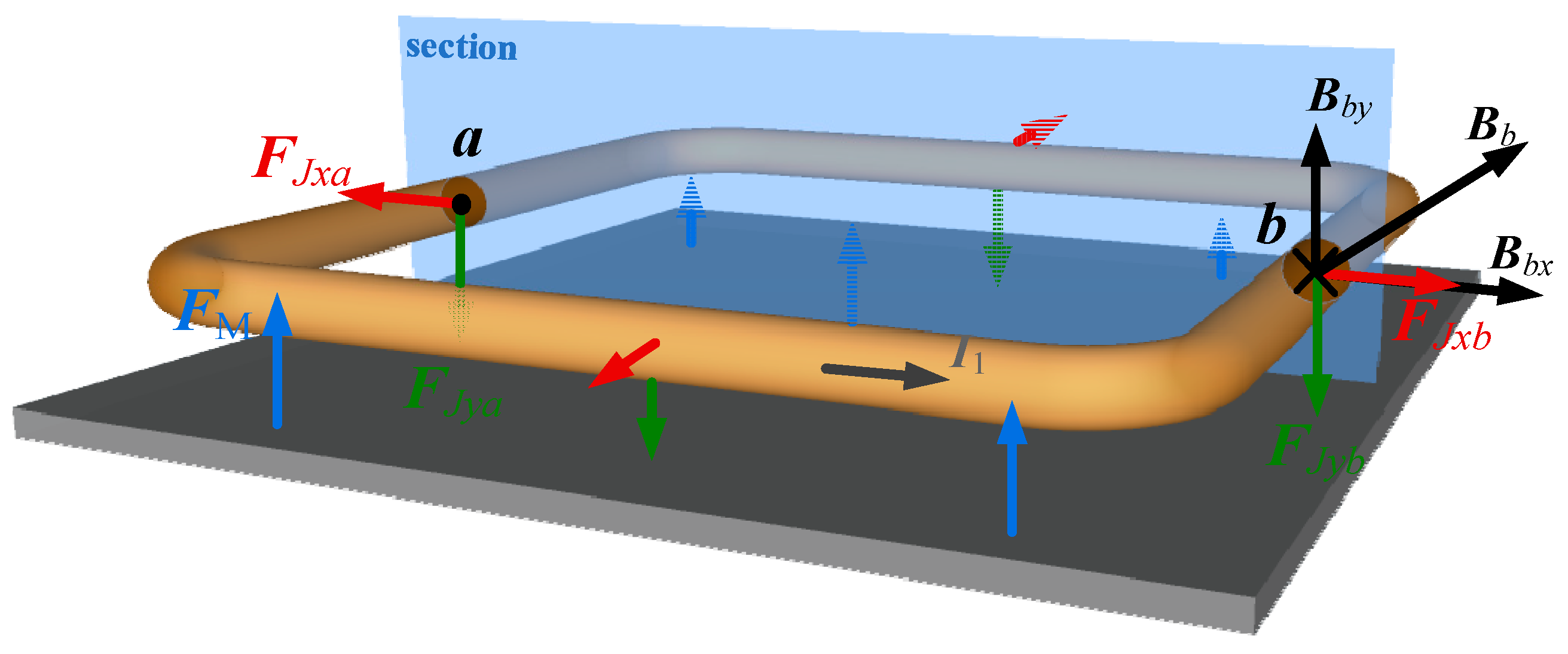
The EMF is of the unidirectional pulsating type because it is proportional to the current squared. Taking a one-turn transmitting coil as an example, the direction of the EMF can be determined by the left-hand rule, as shown in
Figure 6. It can be seen that two tangential forces on the same section of the one-turn coil,
FJxa and
FJxb, are equal in magnitude and opposite in direction. Since the coils in WPT can be regarded as closed coils, the EMF on the coils in the
x-axis cancel each other out [
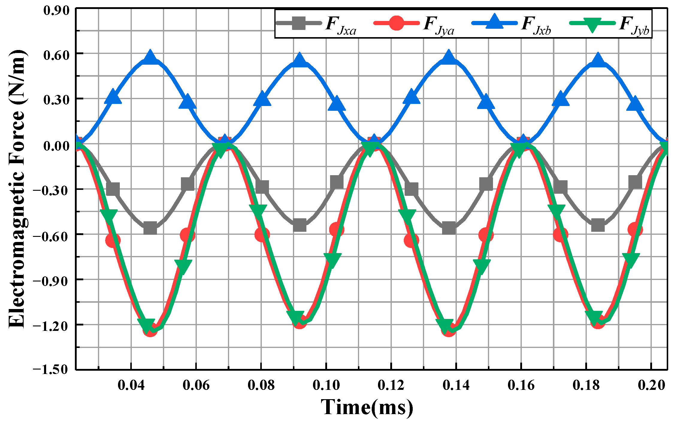
14]. Therefore, for the whole closed coil, the EMF in the x direction is zero. However, the long-term action of the force will make the coil expand or contract gradually, which has a negative influence on the shape and life of the coil. The normal components on the one-turn coil,
FJya and
FJyb, are a constant throughout in the same direction. The variation of the force with time is shown in
Figure 7.
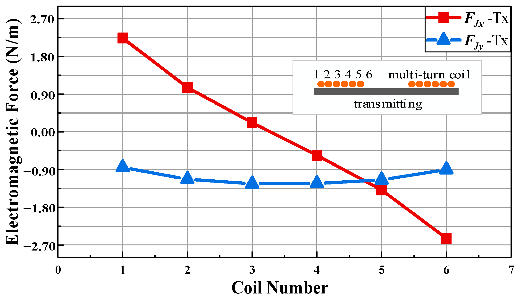
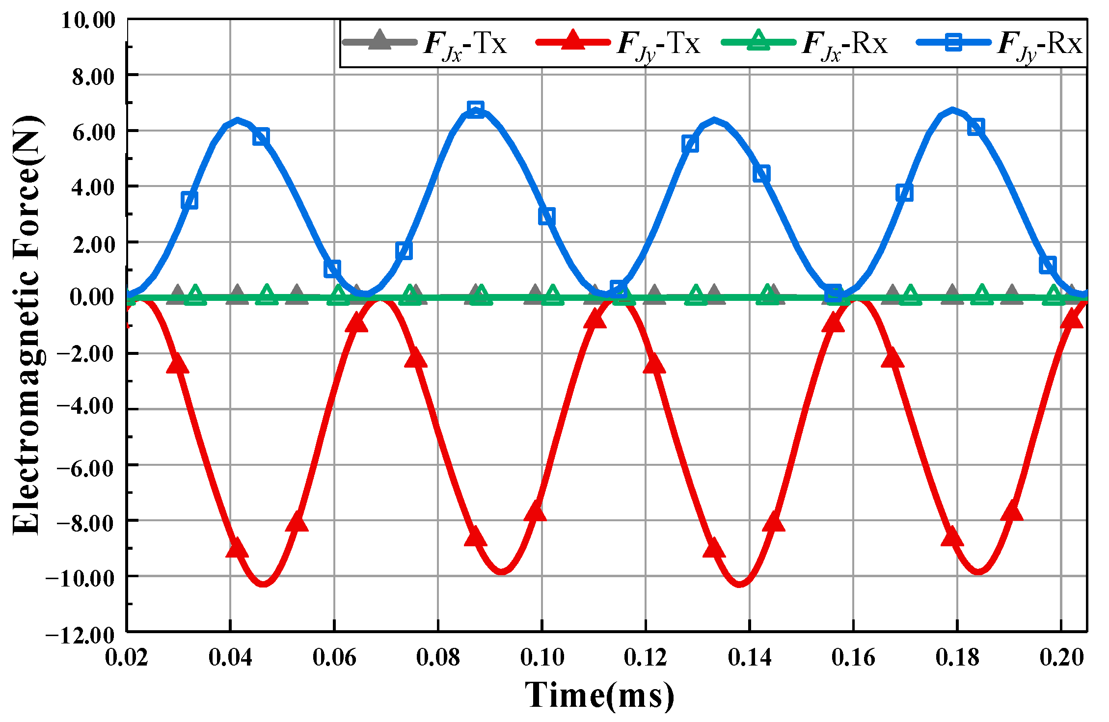
For the whole series-series compensated coupling multi-turn coils, the EMF acting on the coils is the resultant force of
FJ on each one-turn coil. However, because the magnetic field is not uniformly distributed in the coupling space,
Figure 8 shows the EMF on each turn of multi-turn coils. It can be seen that
FJy on the middle turn is the largest, and
FJy on the transmitting coil is always downward. However, the values of
FJx on the side turns are larger, and the directions are inconsistent. By integrating the results of
Figure 8, the EMF of the whole multi-turn coils can be obtained, as shown in
Figure 9.
As a result of the cancellation of FJx on each turn of the coil, FJx on multi-coils is still zero. However, expansion or compression in the radial direction of the coils still exist, which will cause deformation and fracture of the coils. In the commonest WPT systems, the amplitude of the inductive current J2 is less than that of the exciting current J1, k < 1, and the magnetic field near the Rx-coil is lower than that near the Tx-coil. Thus, FJy on the Rx-coil is less than FJy on the Tx-coil. FJy-Tx and FJy-Rx are −10.3 N and 6.2 N, respectively, which is consistent with the rule of Equation (9). Note that, considered from the direction of the magnetic field, FJy-Tx is vertically downward, and FJy-Rx is vertically upward, so their directions are opposite, that is, there is a repulsive force between the transmitting and the receiving coil.
3.4. Electromagnrtic Force on Magnetic Shielding Calculation
From Maxwell theory, the EMF is delivered through the space medium. So,
fM from Equation (1) could be calculated by the Maxwell stress method. The EMF acting on the unit surface area of magnetic shielding is
where
p is the Maxwell tensor, and
n is the normal unit vector of the surface.
Kelvin force
fM is caused by the change in the magnetic permeability
μ at the interface of the ferromagnetic materials and the direction of
fM is from large permeability to low permeability. In a WPT system, the permeability of magnetic shielding
μfer. is about 2500–3500 times
μ0, thus
B is perpendicular to the magnetic shielding surface. The EMF on the magnetic shielding is shown in Equation (12), and its direction is also perpendicular to the surface.
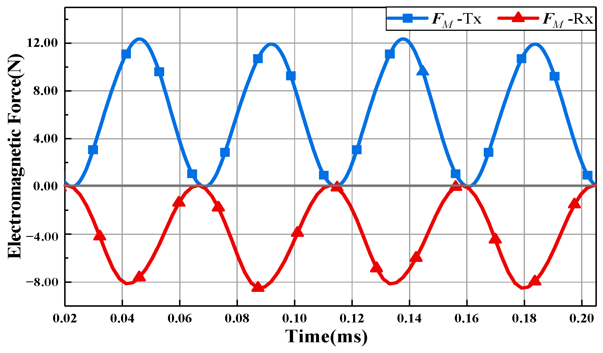
From Equation (12), the amplitude of
FM only depends on the strength of the magnetic field and the shape of the shielding. Since most of the magnetic flux lines go through the shielding, the amplitude of
FM is larger than that of
FJ.
Figure 10 shows that
FM on the transmitting shield is 12.28 N, while
FJy-Tx is only −8.2 N. The direction of
FM should point to the source of the magnetic field, thus
FM points to the coil: in other words, the directions of
FM and
FJ on the transmitting mechanism or the receiving mechanism are opposite.
3.5. Electromagnetic Force Analysis in Frequency
In the time-varying electromagnetic field with resonance angular frequency ω generated by the WPT system, when
J and
B are considered as standard sine functions, expressed by
the EMF density
fJ exerted on coils and the surface tensor
p of magnetic shielding could be obtained as follows:
It can be seen that both Lorentz force and Kelvin force have a steady component and a periodic component. The amplitude of
fJi and
p relate to the phases of the currents,
φJ1 and
φJ2. As the WPT system resonates at the operating frequency ω, the phase difference of the currents is about 90 degrees [
19]. From Equation (14), because
J1J1 >
J1J2 >
J2J2, the directions of the periodic components of
fJ1 and
fJ2 are opposite, which conforms to the conclusion of
Section 3.3. Comparing
Figure 9 and
Figure 10, the directions of the steady components of
FJ and
FM are opposite, which means that they can cancel each other out by using appropriate structure parameters of the system, while the periodic components cannot cancel each other out because of the phase difference between
FJ and
FM. Thus, the influence of the EMF on the WPT system is mainly caused by the periodic components.
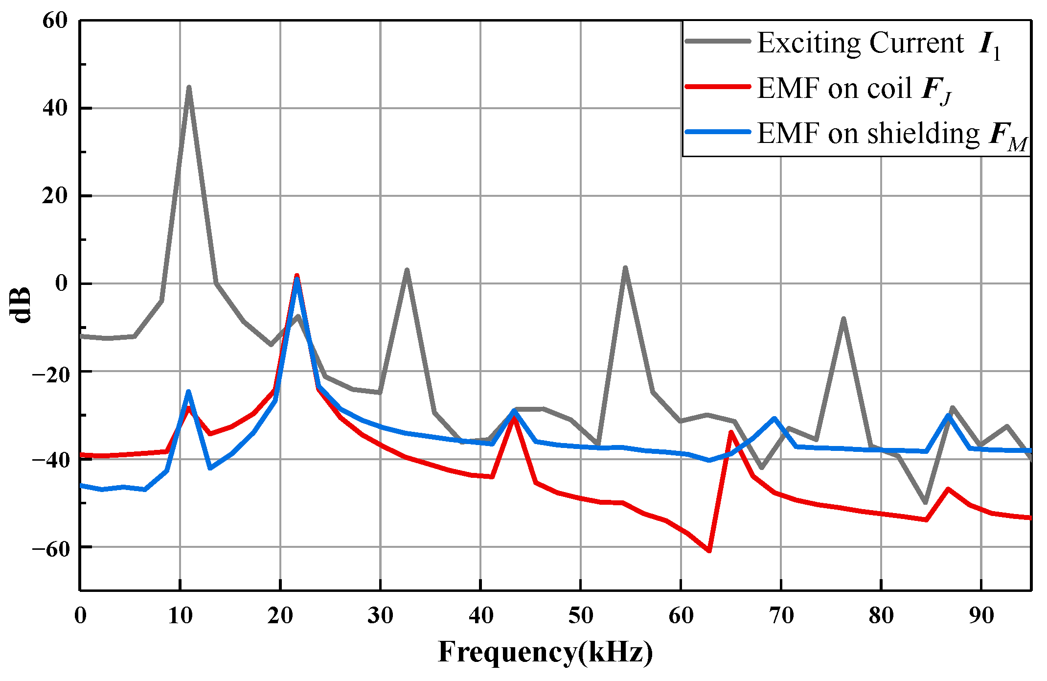
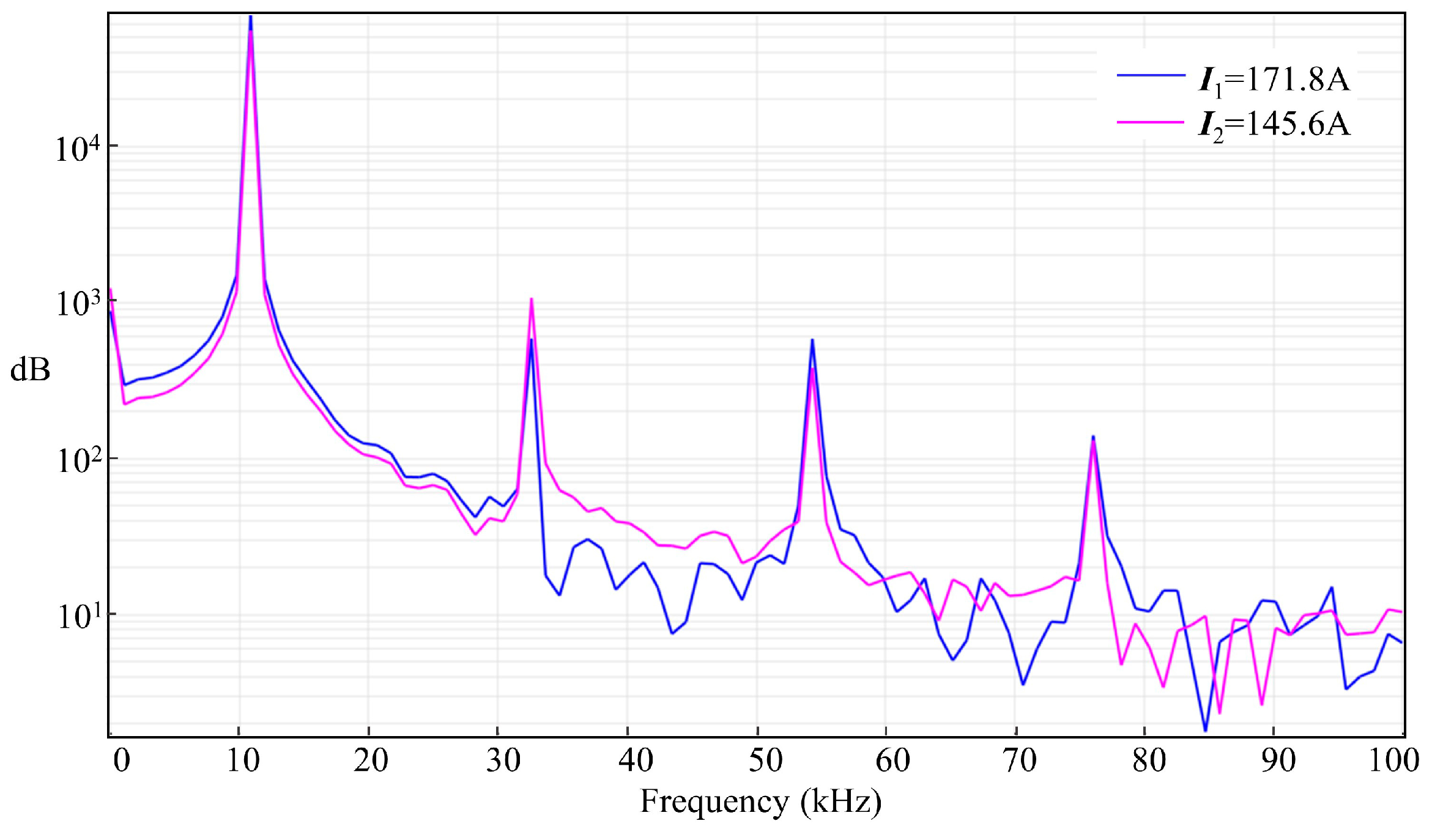
Note that, in Equation (14), the frequency of the periodic force is 21.78 kHz, which is twice that of the system. However, the exciting current often has harmonic components in the actual case, expressed as
where
J0 is the steady component of
J, and
Jn and φ
Jn are the effective value and phase of the harmonic components, respectively. Referring to (14), when the currents have harmonic components, the EMF is represented by the interaction of each harmonic.
Figure 11 shows that the currents in the WPT mainly contain fundamental and odd harmonics, such as third harmonic and fifth harmonic, and the fundamental is the biggest component. Thus, the main frequencies of the EMF harmonic components are 21.78 kHz, 43.56 kHz, 65.34 kHz, as shown in
Figure 11. Meanwhile, the component of the EMF at 21.78 kHz frequency is still dominant.
5. Conclusions
In this paper, the characteristics of the EMF in a high-power WPT system were studied by theoretical analysis and simulation. The coils will keep expanding or compressing in the radial direction and repel each other in the axial direction because of the effect of the EMF. The EMF on a multi-turn coil is represented by the superposition of different forces on each turn, and the EMF on the coils and the magnetic shielding are in opposite directions. By frequency-field analysis, the resultant EMF on the coupling mechanism contains a steady component and a periodic component, and the periodic component mainly contains the fundamental and the even frequency. The amplitude of the EMF can be solved by the finite element method, which will increase rapidly with the increase of the current and the magnetic field. When the exciting current is 171A, the EMF values on the 6-turn, 10-turn, and 15-turn coil are 10.3 N, 18.88 N and 24.85 N, respectively. In future work, we will propose a smooth method to reduce the EMF on the coupling mechanism of the high-power WPT system and explore the effect of EMF on a dynamic WPT system and the EMF on the external metal foreign body to improve the stability and reliability of WPT systems.


