1. Introduction
An inspection robot is a special kind of industrial robots. It has been applied in smart factories and substations to replace the manual inspection tasks. The movement and the operation of the inspection robot depend on the carried batteries. At present, the batteries in inspection robots are charged with contact-type charger. The contact charging method, which depends on the manual or mechanical plug-in, is characterized by the issues of frequent inflexible charging and electric shock hazard.
Wireless power transmission technologies, especially the wireless power transmission technology based on magnetic coupling, have been developed rapidly [
1,
2]. Research on wireless power transmission technology based on magnetic coupling mainly include the high frequency inverters [
3,
4], magnetic couplers [
5,
6], compensation circuits [
7,
8], power rate promotion [
9,
10], and the electromagnetic safety issue [
11,
12]. This technology is applied in fields, such as medical implants [
13], electronic devices, smart home devices, electric vehicles [
14,
15], and drones [
16]. The wireless power transfer technology is also applied in wireless powered communication networks [
17,
18] and the wireless powered sensor networks [
19], which are characterized by the low power rate but wide transfer range (compared with the coil size).
The inflexible charging and the electrical shock hazard issues can be solved by the static wireless power transmission technology. To decrease the dependence on batteries and extend the driving range, researchers proposed the dynamic wireless charging technology. For electric vehicles, the energy is transferred wirelessly through the magnetic coupling between the transmitting coils in road and the receiving coil on a moving electric vehicle in the dynamic wireless charging system. According to the transmitting coil structure, the dynamic wireless charging systems can be divided into systems with long rail structure and systems with short-segmented coil structure [
14]. When compared with the system with long rail structure, the transmitting coils are controlled and energized according to the position of receiving coil in the system with short segmented coil structure. The loss in primary side and the area of the electromagnetic leakage are smaller because most of the short segmented transmitting coils are not energized. However, the system with short segmented coils relies on the positioning method and the switching control devices of the transmitting coils. The three coil detection system, which is independent of the energy transfer system, was proposed to detect the moving electric vehicle in [
20]. The positioning method for obtaining the location of the moving objects is the foundation of the dynamic wireless charging system with short-segmented coils. The external positioning sensor (infrared sensor or magnetic sensor), measuring the current change in primary side, measuring the voltage change in secondary side, or detecting the magnetic field change are usually applied as the positioning methods. In this paper, the dynamic wireless charging system for inspection robot is proposed to solve the charging problems, decrease the battery size, and promote the ability of all-weather work.
In the dynamic wireless charging system with short segmented coils in [
21], the receiving coil and the single energized short segmented transmitting coil are designed symmetrically and identically. In the system with symmetric transceiver, if the short segmented transmitting coils are energized one by one, the receiving power drops significantly when the receiving coil moves to the position between two transmitting coils. To solve this issue, the switching control of double energized transmitting coils with the switching control of the compensation capacitors is proposed in [
22]. The switching control of double energized transmitting coils with the shift of the operation frequency is proposed in [
23]. In [
22,
23], the power fluctuation issue is solved by the controls in primary side. The switching controls of the primary coils with other auxiliary controls (switching control of the compensation capacitors or shifting of the operation frequency) are applied for power stabilization. In this paper, the receiving structure in the secondary side is designed to solve this issue. An asymmetric transceiver including the single energized transmitting coil and two identical receiving coils that are connected in series is proposed. Hence, when comparing with the existing research mentioned before, the switching control of the compensation capacitors or shifting of the operation frequency is not needed. The control complexity of the whole system is reduced by the design of asymmetric transceiver structure.
In this paper, the design of the receiving side is investigated to solve the power fluctuation during the moving process of the receiving coil. The dynamic wireless charging system with short-segmented transmitting coils based on the asymmetric transceiver is introduced. The proposed asymmetric transceiver includes the single energized transmitting coil and two identical receiving coils that are connected in series. The circuit models of the systems with symmetric and asymmetric transceivers are developed according to the circuit theory. The expressions of the receiving power and the efficiency in terms of the mutual inductance between the transmitting and receiving coils for different systems are derived. The characteristics of the receiving power and the efficiency varying with the position change of the receiving devices in one cycle of switching control of the transmitting coils are analyzed based on the mutual inductance calculation. According to the comparative results, the power drop issue when the receiving device moves to the switching control position of the transmitting coils in dynamic wireless charging system with symmetric structure is solved by the proposed asymmetric transceiver with double receiving coils. The theoretical analyses are verified experimentally.
2. System Description
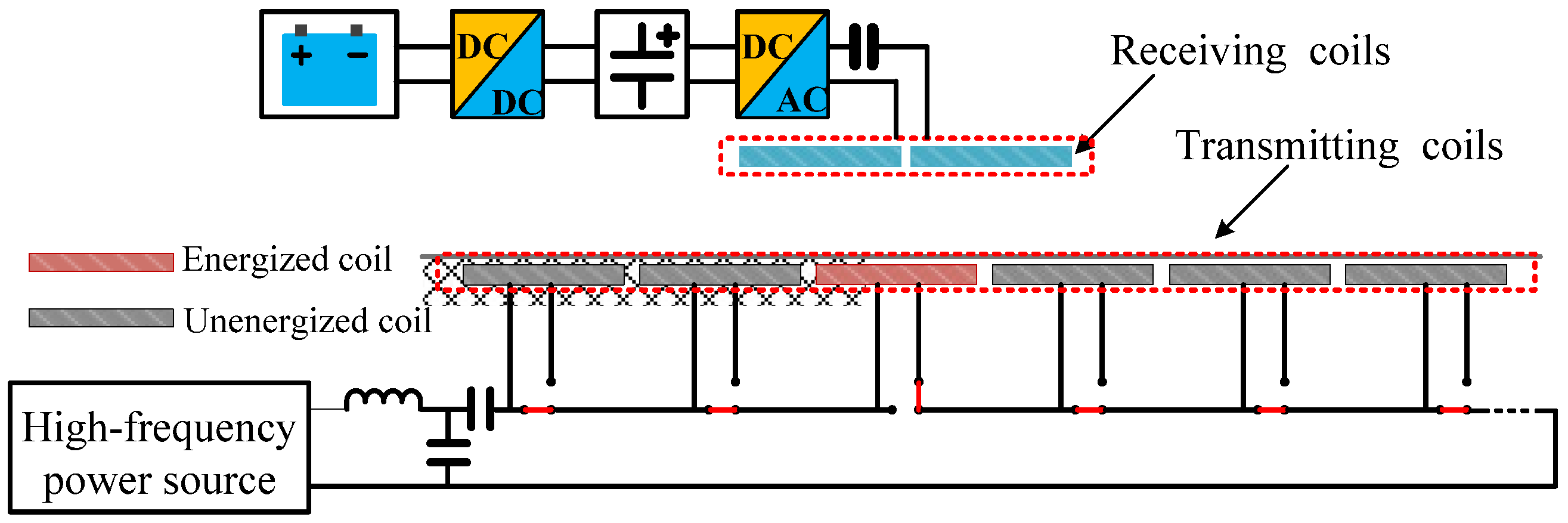
In the proposed short-segmented dynamic wireless charging system based on the asymmetric transceiver, the transmitting coils are energized one by one according to the position of the inspection robot. The proposed asymmetric transceiver includes the single energized transmitting coil and two identical receiving coils connected in series. The schematic diagram of the proposed system with asymmetric transceiver is shown in
Figure 1.
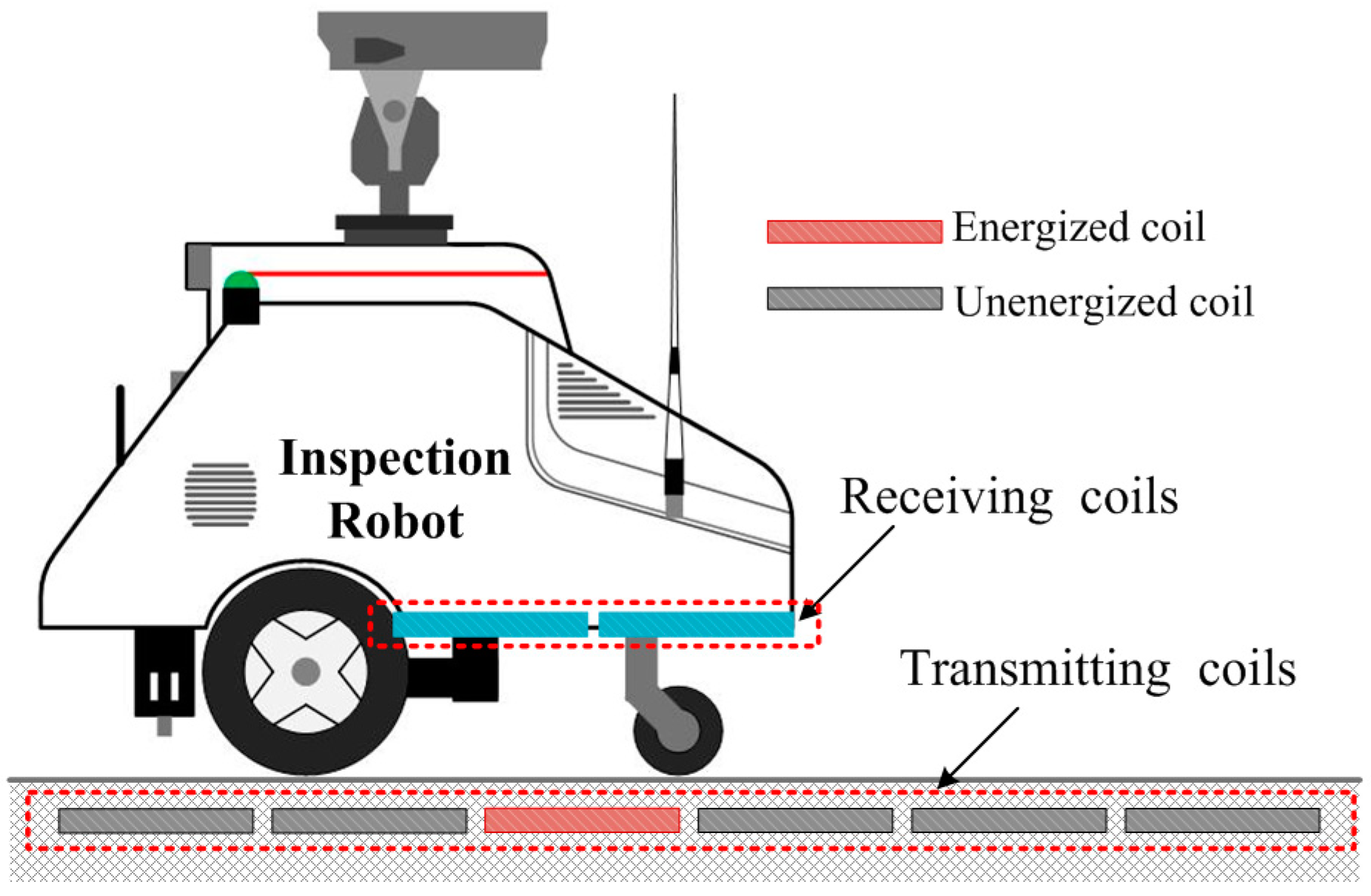
The structure diagram of the proposed dynamic wireless charging system for inspection robot is shown in
Figure 2. The transmitting coils are short segmented square coils that can be controlled by the switching devices and energized one by one. The single coils in both symmetric and asymmetric transceivers are designed identically in this paper. In the system with symmetric transceiver, the receiving device includes only one coil. In the system with asymmetric transceiver, the receiving device consists of two coils connected in series. The primary side of this system includes the high-frequency inverter, primary compensation circuit, switching control devices, and the transmitting coils. The secondary side consists of two receiving coils connected in series, secondary compensation circuit, rectifier circuit, filter circuit, (direct-current) DC converter circuit, and the battery. LCC compensation circuit is applied in the primary side to maintain the current through the transmitting coil. The capacitor is connected with the receiving coils in series. The energy is transferred from the road side to the inspection robot through the magnetic coupling between the transmitting coil and the receiving coils. The positioning method for obtaining the location of the moving objects is also needed as the foundation in the dynamic wireless charging systems with short-segmented coils. In this paper, we concentrate on the characteristics of the receiving power and efficiency varying with the position of receiving devices during one cycle of the switching control of the transmitting coils. Hence, the positioning method to obtain the exact location of the robot is assumed to be given in this paper.
3. System Modeling
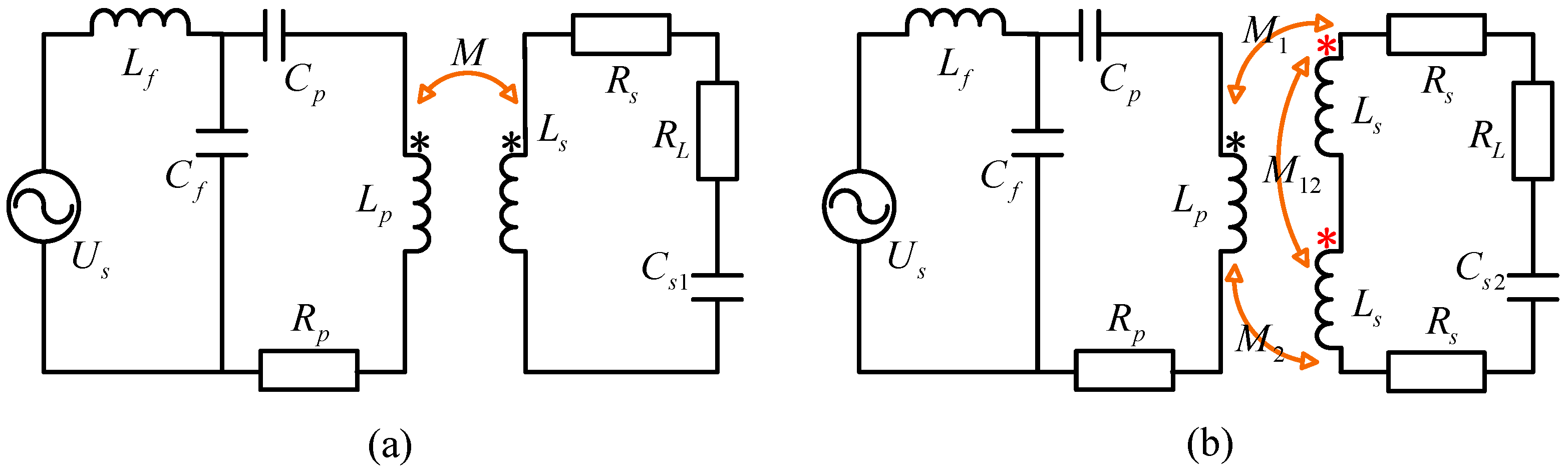
In a dynamic wireless charging system for the inspection robot with the transmitting coils energized singly, the receiving side includes single coil in the symmetric structure while double coils in series in the asymmetric structure. The comparative system models of the symmetric and asymmetric structures are shown in
Figure 3.
Us is the high-frequency power source.
Lp and
Rp are the inductance and resistance of the single transmitting coil.
Lf,
Cf, and
Cp are the inductance and capacitors in the compensation circuit of the transmitting side.
Ls and
Rs are the inductance and resistance of the single coil in receiving devices. In the system with symmetric structure,
Cs1 is the compensation capacitor in receiving side and
M is the mutual inductance between the transmitting coil and the receiving device. In the system with asymmetric structure,
Cs2 is the compensation capacitor for the double receiving coils.
M1 and
M2 are the mutual inductances between the single transmitting coil and the two receiving coils separately.
M12 is the mutual inductance between the two receiving coils. In order to simplify the theoretical analysis in this paper, the rectifier circuit, filter circuit, DC converter circuit, and the battery are equivalent to the alternating-current (AC) resistance
RL. In the dynamic wireless charging system for inspection robot, the battery is the same approximately during system operation. Hence, the load is fixed in this paper.
As shown in
Figure 3, the LCC compensation circuit is applied in the transmitting side. In order to realize the stable current through the transmitting coil, the capacitors and inductances should satisfy the condition that
where
ω = 2
πf and
f is the operation frequency.
Then, the current through the transmitting coil is
The capacitors in receiving side of the systems with symmetric and asymmetric transceivers should satisfy
According to Equation (4), the compensation capacitor Cs2 in receiving side of the system with asymmetric transceiver is influenced by the mutual inductance M12.Because of the existence of mutual inductance M12, the compensation capacitor Cs2 is not equal to a half of the compensation capacitor Cs1 simply. The compensation capacitor should be designed according to Equation (4). Otherwise, the total impedance in the receiving circuit will enlarge, and the receiving power as well as the efficiency will drop.
When the receiving circuit is in resonance, according to the circuit theory of the mutual inductance, the currents through the receiving coils of the different systems can be derived as
The expressions of receiving power are derived comparatively as
The expressions of efficiency are derived, respectively, as
In the dynamic wireless charging system for inspection robot, the relevant position between the transmitting coil and the receiving coil is changing during the moving process of the inspection robot. In the conventional system with symmetric transceiver, the mutual inductance between the transmitting and receiving sides fluctuates sharply because of the position changing. According to the expressions that are derived in this section, the fluctuation of the mutual inductance will decrease the stabilization of the receiving power in the system with the symmetric transceiver. To solve the issue of power fluctuation, the asymmetric transceiver is proposed in this paper. The comparative characteristics of the systems with the symmetric and asymmetric structures varying with the changing position of the receiving devices in one cycle of switching control of the transmitting coils are investigated in the following sections.
4. System Analysis
The transmitting coils are energized one by one according to the position of the receiving devices in dynamic wireless charging system in this paper. So, the system characteristics, including the receiving power and the efficiency, are studied comparatively during one cycle of the switching control of the transmitting coils. The transmitting coils and receiving coils are square coils designed identically. The mutual inductance between the coils can be calculated according to
where
μ0 is the vacuum permeability,
N is the turns number of the coils,
l1 and
l2 are the single loops of the transmitting and receiving coils. d
l1 and d
l2 are the infinitesimals in the transmitting and receiving loops.
R is the distance between the infinitesimals.
The total mutual inductances between the energized transmitting coil and the receiving device in systems with symmetric and asymmetric transceivers can be expressed as
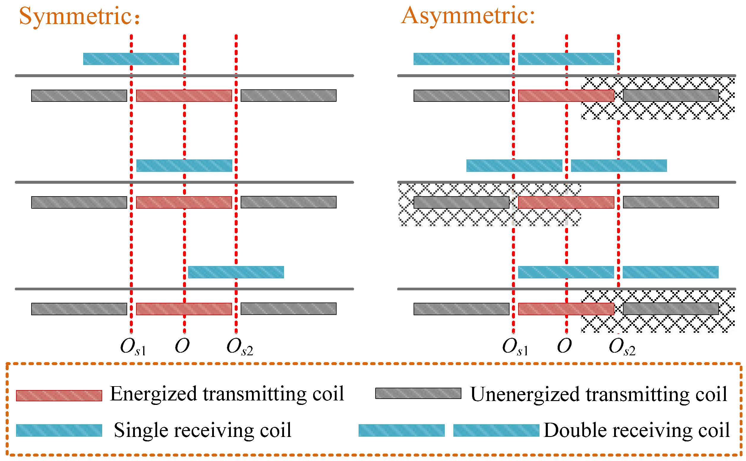
The positions of the receiving devices in systems with symmetric and asymmetric transceivers change in the area corresponding to the single energized transmitting coil.
O is the position of the center point of the energized transmitting coil.
Os1 and
Os2 are the positions of the switching control points of the transmitting coil. The comparative position diagram of the systems with symmetric and asymmetric transceivers is shown in
Figure 4.
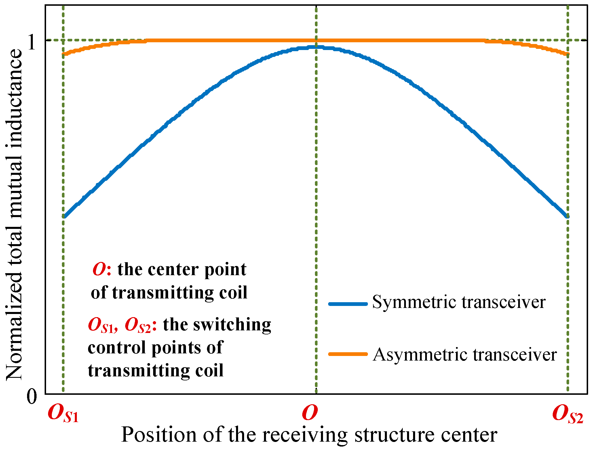
To obtain the characteristics of the receiving power and efficiency varying with the position of receiving devices in one cycle of the switching control of the transmitting coils, the numerical calculation method is applied in this paper, according to the derived formulas before. The values of the turns number of the coils, the length of the side, and the vertical height are set firstly. Then, changing the horizon position of the receiving structure, the mutual inductances
M,
M1, and
M2 are calculated at different positions successively, according to Equation (8). The total mutual inductances between the energized transmitting coil and the receiving device in systems with symmetric and asymmetric transceivers can be calculated further based on Equation (9). In this paper, the comparative characteristics of the total mutual inductances varying with the position changing of the receiving devices in systems with symmetric and asymmetric transceivers are shown in
Figure 5. The total mutual inductances are normalized according to the maximum value in them.
As shown in
Figure 5, as compared with the symmetric structure, the total mutual inductance of the asymmetric structure varying with the position changing of the receiving devices is more stable, especially at the positions (
Os1 and
Os2) of the switching control points of the transmitting coil. The voltage of the high-frequency power source, the resistances of the coils, the resistance of the load, and the inductance
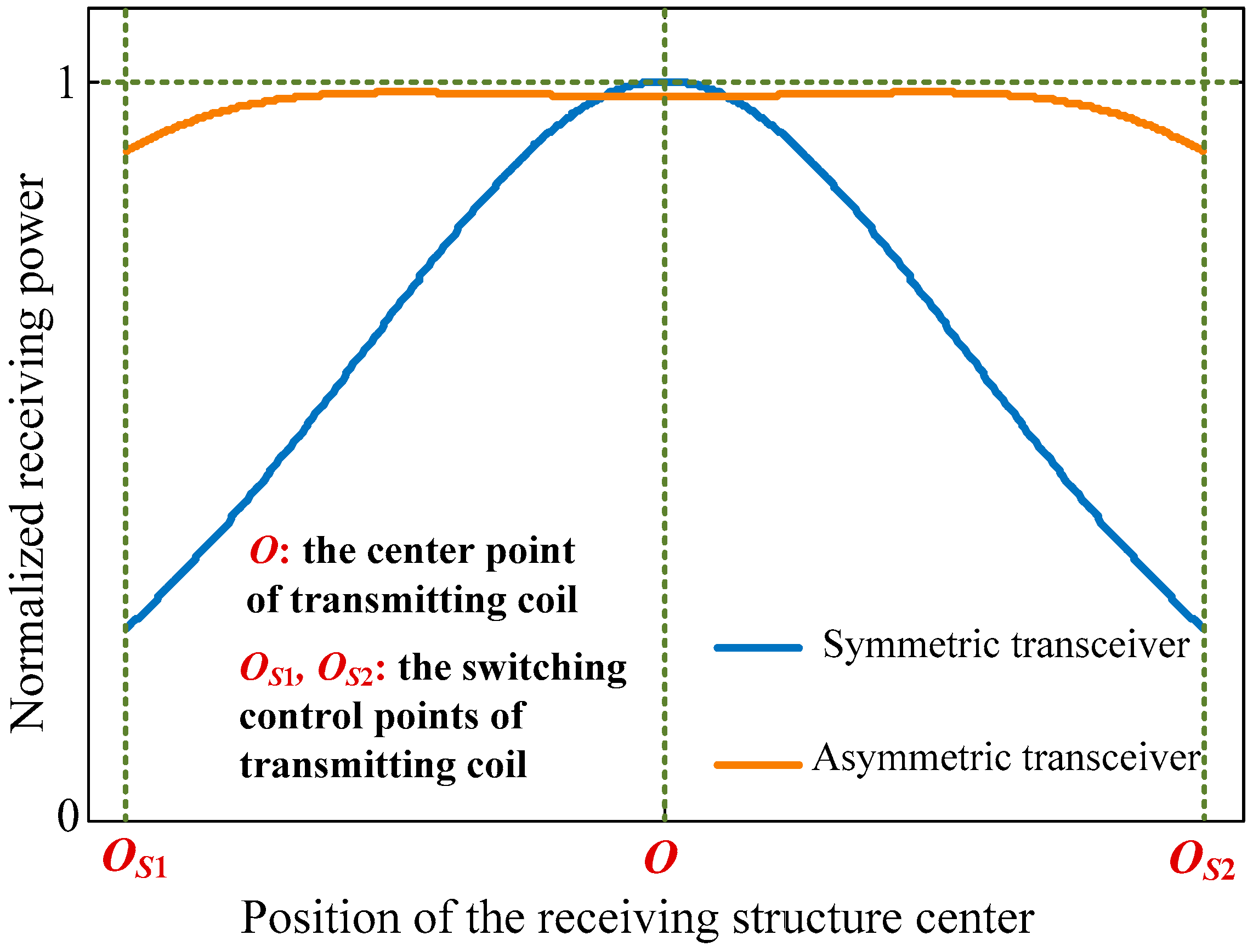
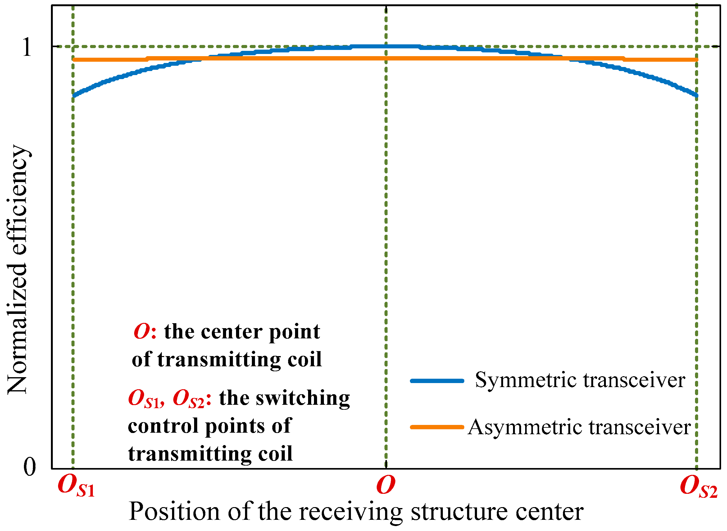
Lf are set. The receiving power and the efficiency when the receiving devices are at different positions in systems with symmetric and asymmetric transceivers can be calculated according to Equations (6) and (7). The comparative characteristics of the receiving power and the efficiency varying with the position changing of the receiving devices are calculated as shown in
Figure 6 and
Figure 7. The receiving power and the efficiency are normalized according to the maximum value, respectively.
According to the system characteristics that are shown in
Figure 6 and
Figure 7, the receiving power and efficiency of the system with symmetric transceiver drops when the receiving structure is at the positions of switching control. In the system with the proposed asymmetric transceiver in this paper, the receiving power and the efficiency are more stable during the moving process of the receiving device, especially when the receiving device is at the positions of switching control of the short-segmented transmitting coils.
5. Experiments and Discussion
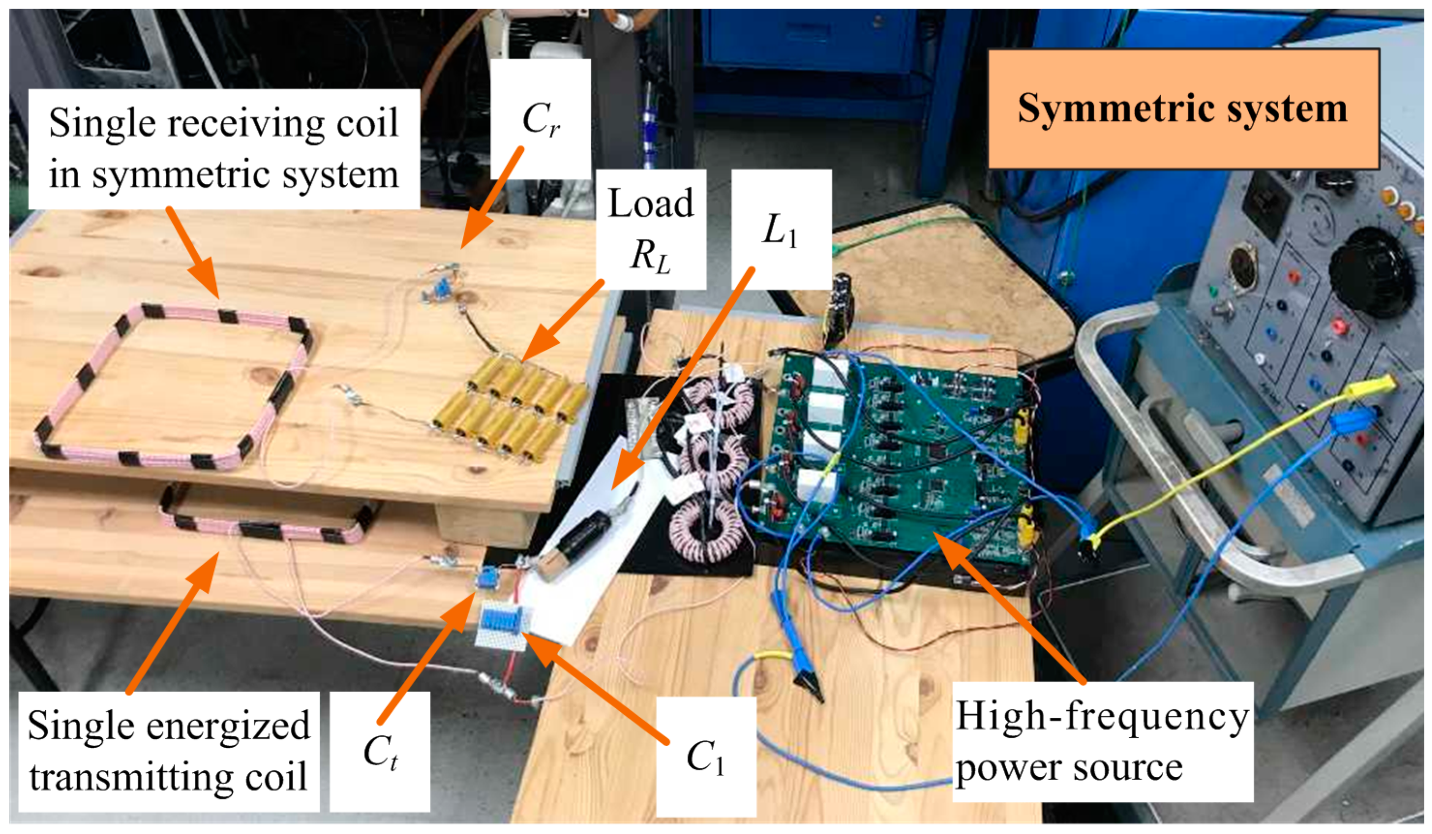
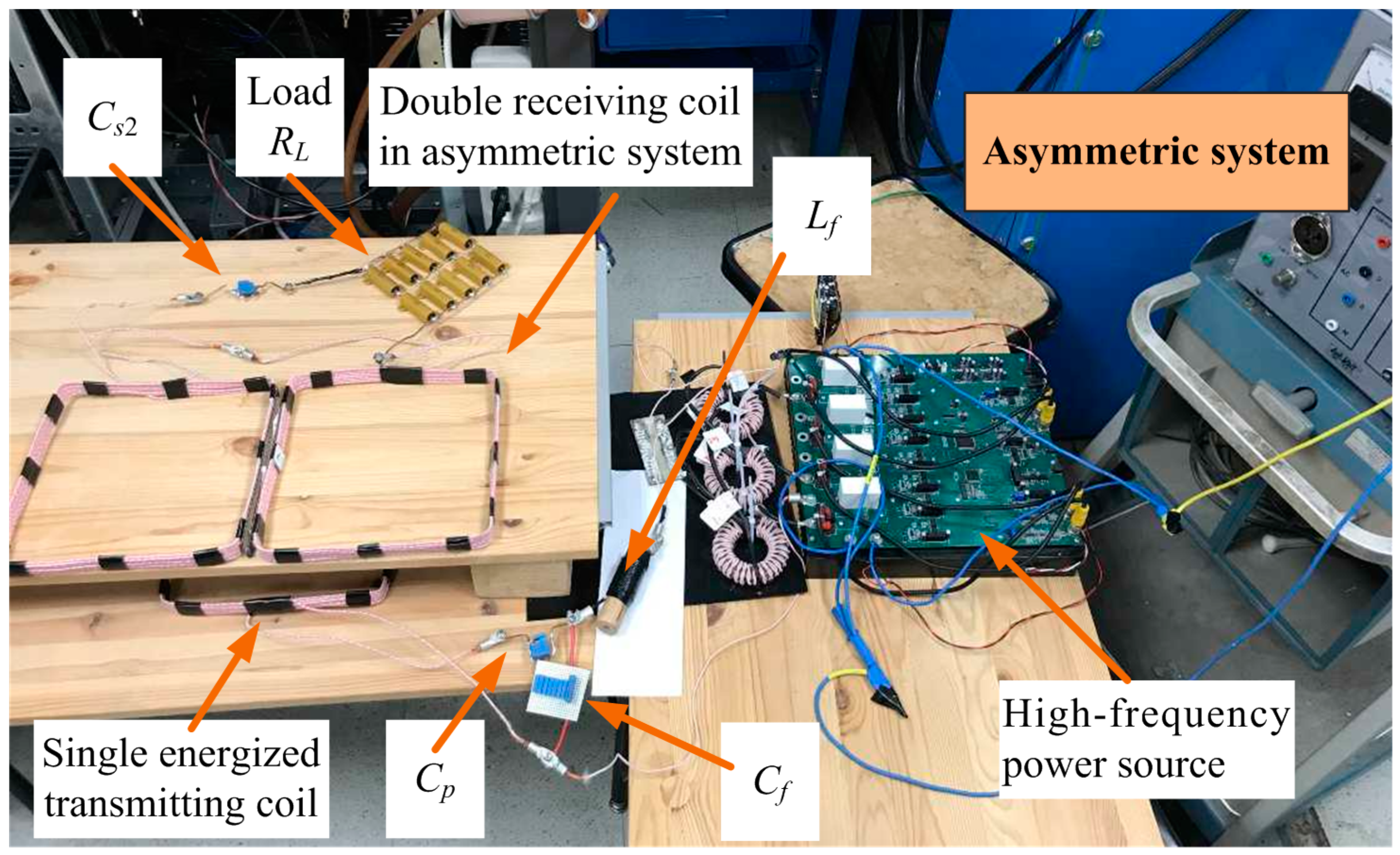
An experiment is carried out to verify the theoretical analysis. This paper concentrates on the system characteristics during the moving process of the receiving devices in one cycle of the switching control of the transmitting coils. The prototype of the dynamic wireless power transfer systems with single energized transmitting coil with symmetric and asymmetric transceivers are set up, as shown in
Figure 8 and
Figure 9. In the two system prototypes, the transmitting sides include the high-frequency inverter, the LCC compensation circuit in transmitting side, and the single energized transmitting coil. In the system prototype with symmetric transceiver, the receiving side includes only one receiving coil. In the system prototype with asymmetric transceiver, the receiving side contains two receiving coils that are connected in series. The compensation capacitor in receiving side and the load are also included in receiving sides, respectively. The coils are designed identically in this paper. The side length is 23 cm. The turns number is 8. The inductance of single coil is 37.9 μH.
Lf in primary compensation circuit is 5.0 μH. According to Equations (1) and (2),
Cf is calculated and designed as 701.2 nF (the measured value is 700.5 nF) and
Cp is calculated and designed as 106.6 nF (the measured value is 106.9 nF). According to Equation (4), the secondary compensation capacitor in the system with symmetric transceiver is designed as 92.5 nF (the measured value is 92.1 nF). In the system with asymmetric transceiver, the inductance of two receiving coils connected in series is measured as 66.2 μH. The secondary compensation capacitor is designed as 53.0 nF (the measured value is 52.8 nF). The output voltage of the high-frequency inverter is 20 V. The operation frequency is 85 kHz. The resistance of the load is 4.2 Ω.
In the systems with symmetric and asymmetric transceivers, the positions of the receiving devices change in the area corresponding to the single energized transmitting coil, respectively. The voltage of the load is measured when the receiving devices are at different position. The experimental characteristics of the receiving power varying with the position changing of the receiving devices in one cycle of switching control of the transmitting coils are shown in
Figure 10 comparatively.
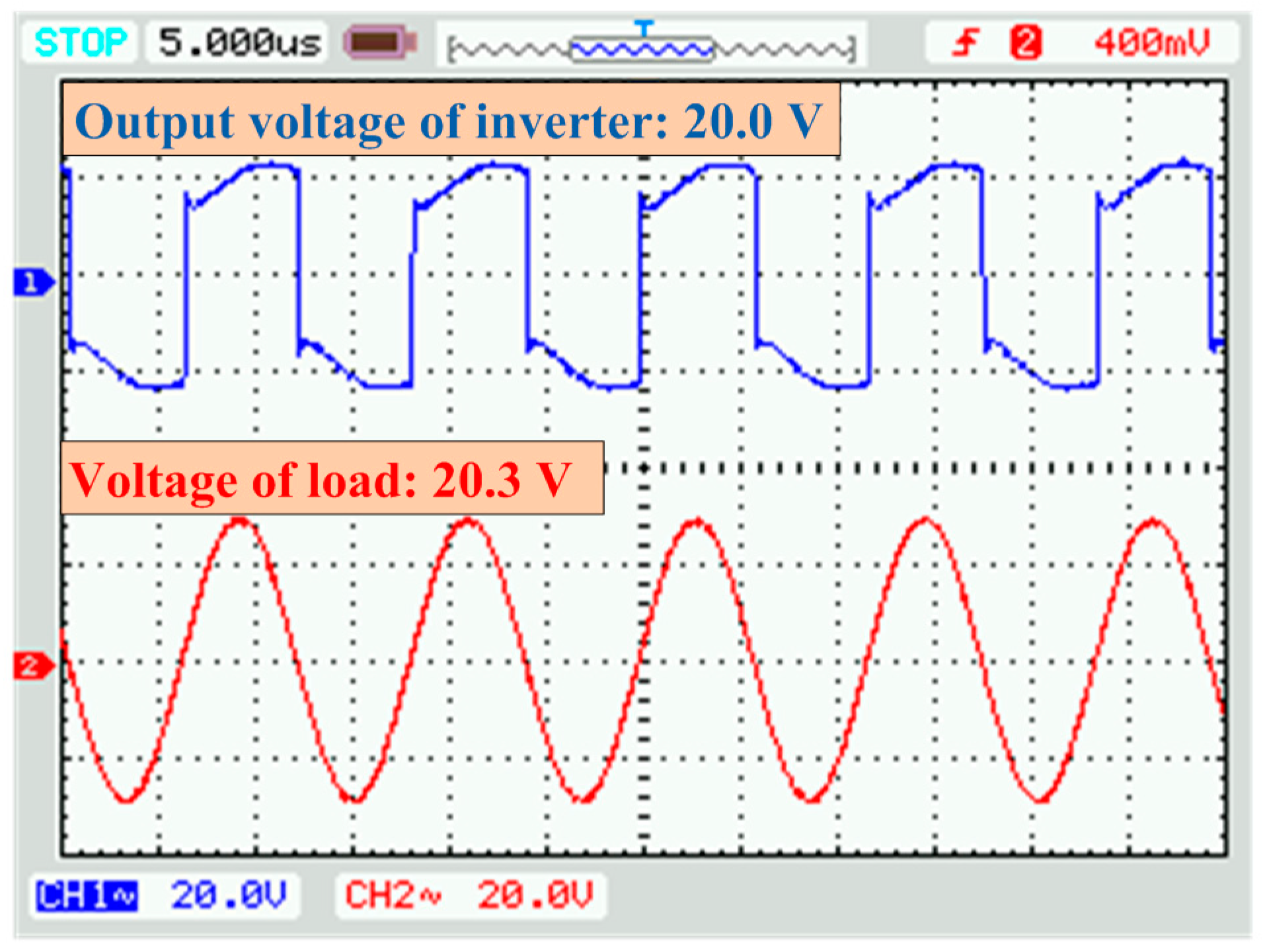
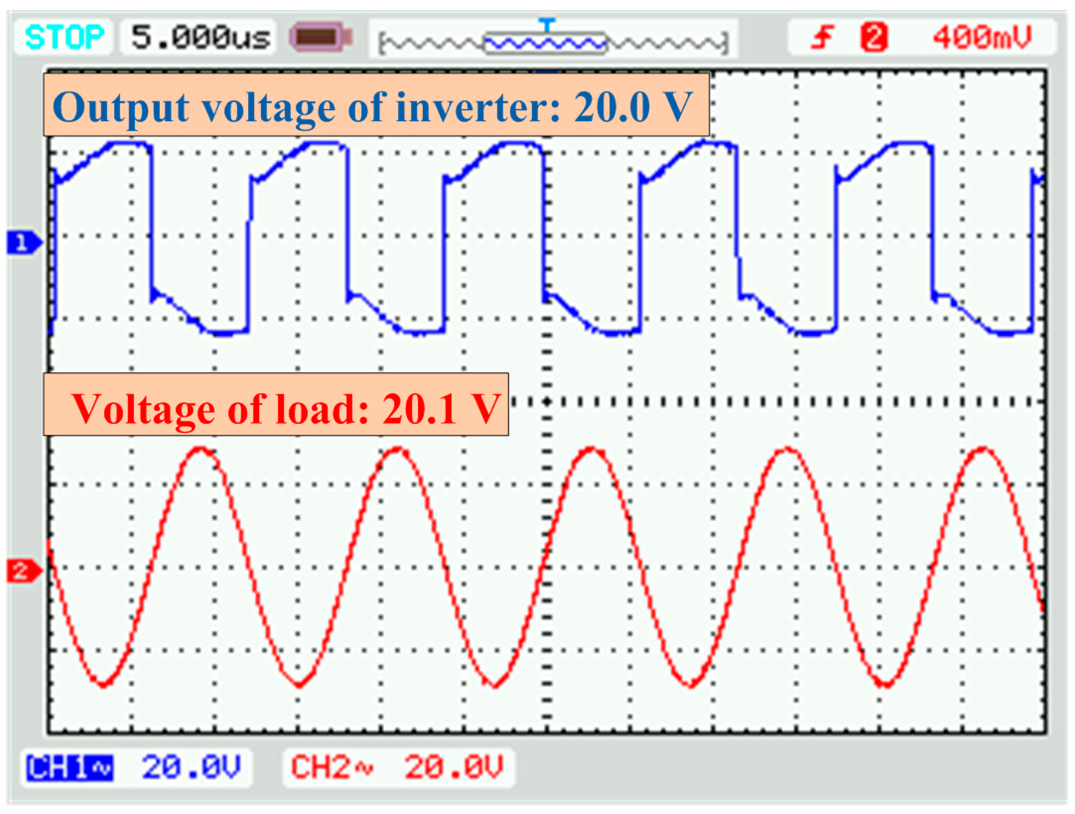
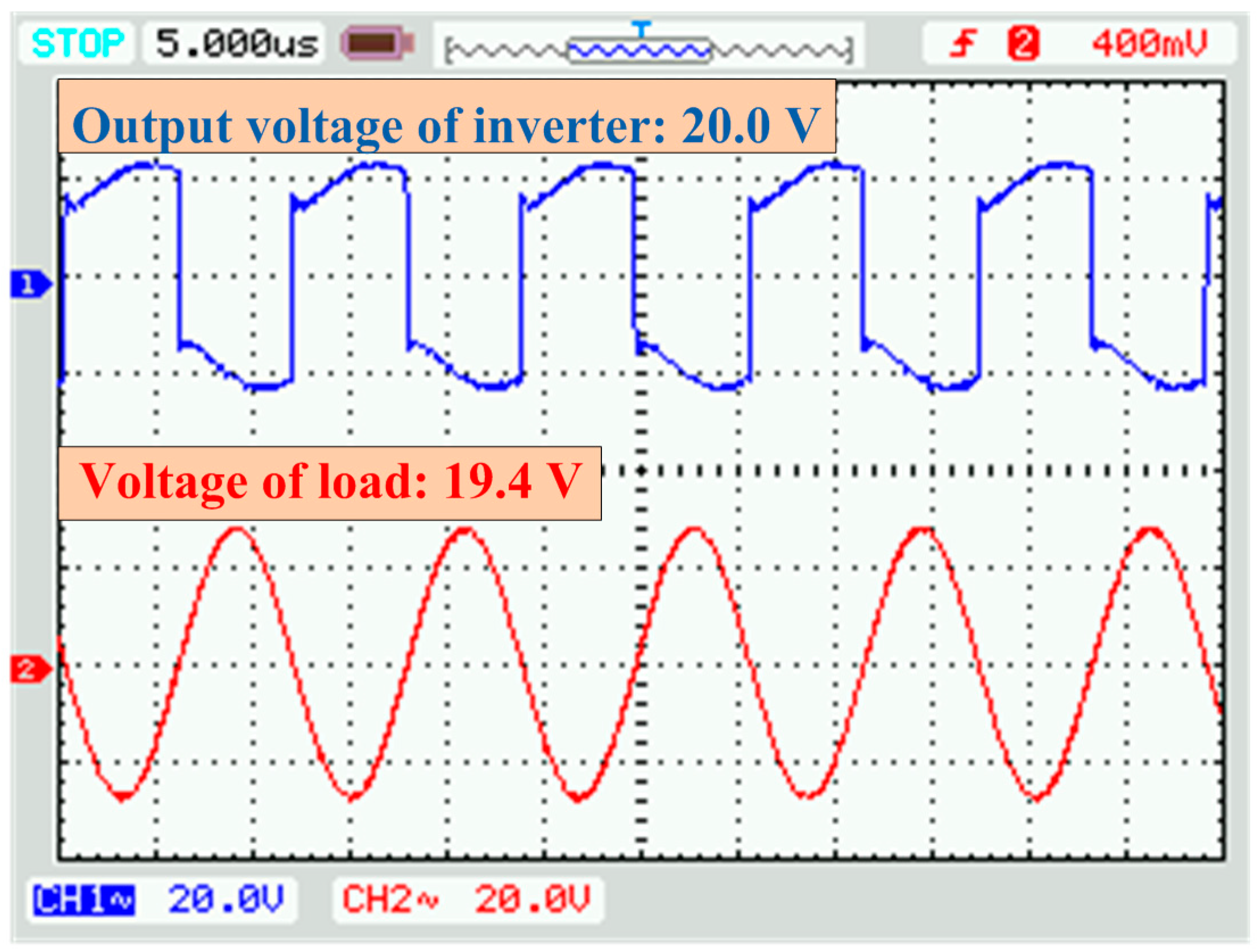
When the receiving structures are at the position of the center point of the single energized transmitting coil, the waveforms of voltages of the inverter output and the load in the systems with symmetric and asymmetric transceivers are shown in
Figure 11 and
Figure 12, respectively. At the position of the center point of the single energized transmitting coil, the receiving power is 98.1 W and efficiency is 88.6% in the system with symmetric transceiver. The receiving power is 96.2 W and efficiency is 87.8% in the system with an asymmetric transceiver.
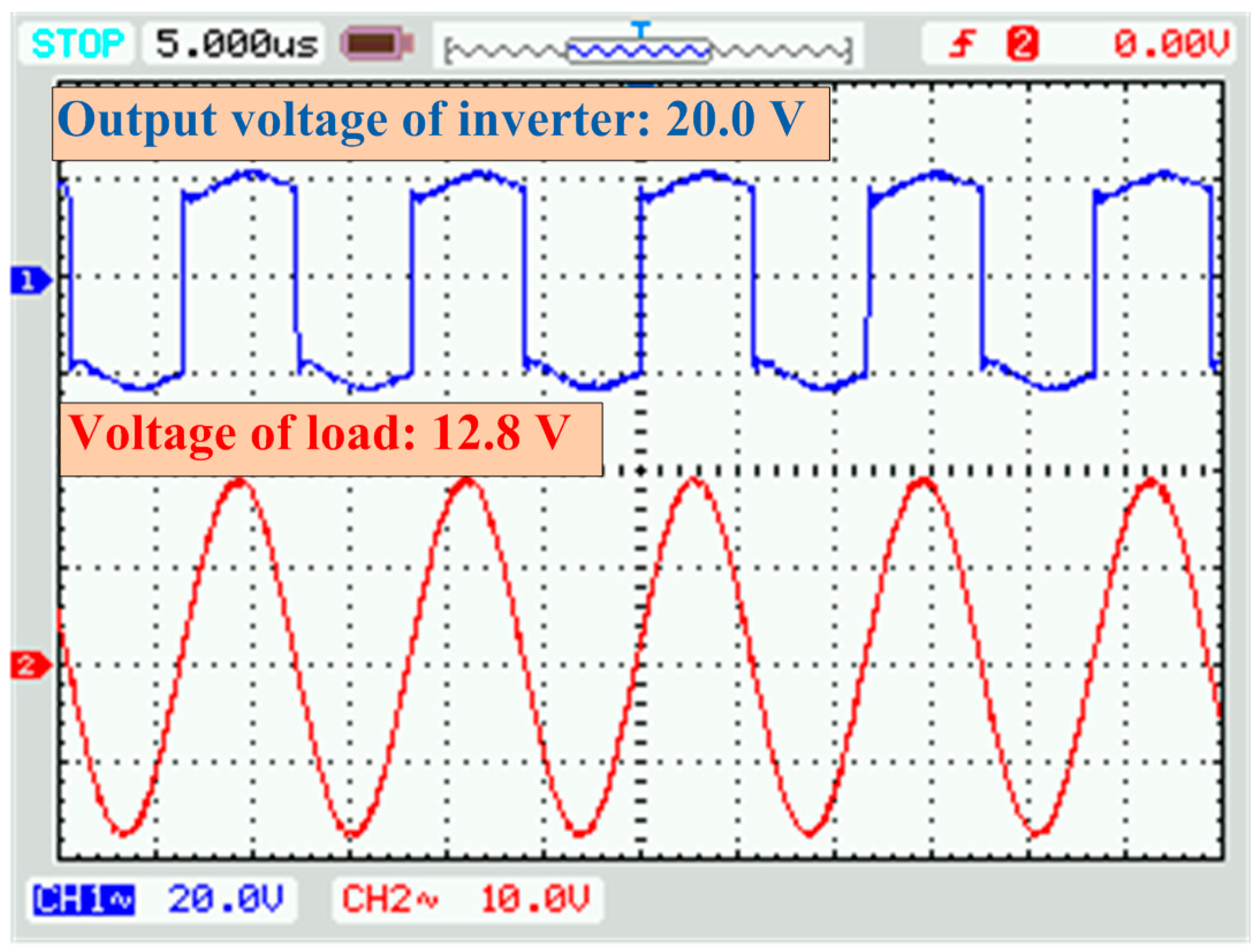
When the receiving structures are at the position of the switching control of the transmitting coil, the waveforms of voltages of the inverter output and the load in the systems with symmetric and asymmetric transceivers are shown in
Figure 13 and
Figure 14, respectively. At the position of the switching control of the transmitting coil, the receiving power is 39.0 W and the efficiency is 78.4% in the system with symmetric transceiver. The receiving power is 89.6 W and efficiency is 87.3% in the system with asymmetric transceiver.
According to the comparative experimental results that are shown above, the issue of power fluctuation in the system with the symmetric transceiver is solved by the proposed asymmetric transceiver. At the position of the center point of the single energized transmitting coil, values of the receiving power and the efficiency of the systems with symmetric and asymmetric transceivers are approximately equal. When compared with the system with symmetric transceiver, the values of the system with asymmetric transceiver are slightly lower caused by the larger resistance in receiving side and the approximate total mutual inductance. When compared with the system with symmetric transceiver at the position of the switching control of the transmitting coil, the values of the receiving power and the efficiency of the system with asymmetric transceiver are significantly higher. The receiving power is improved from 39.0 W to 89.6 W and the efficiency is promoted from 78.4% to 87.3%.


