Analysis of Torque Ripple and Cogging Torque Reduction in Electric Vehicle Traction Platform Applying Rotor Notched Design

1
EV Components & Materials R&D Group, Korea Institute of Industrial Technology, 6 Cheomdan-gwagiro 208 beon-gil, Buk-gu, Gwangju 61012, Korea
2
Department of Electrical Engineering, Chonnam National University, 77 Youngbong-ro, Buk-gu, Gwangju 61186, Korea
3
Robotics and Virtual Engineering, Korea University of Science and Technology, Daejeon 34113, Korea
*
Author to whom correspondence should be addressed.
Energies 2018, 11(11), 3053; https://doi.org/10.3390/en11113053
Submission received: 9 October 2018
/
Revised: 22 October 2018
/
Accepted: 29 October 2018
/
Published: 6 November 2018
(This article belongs to the Special Issue Energy Efficiency in Electric Devices, Machines and Drives)
Abstract
:Drive motors, which are used in the drive modules of electric cars, are interior permanent magnet motors. These motors tend to have high cogging torque and torque ripple, which leads to the generation of high vibration and noise. Several studies have attempted to determine methods of reducing the cogging torque and torque ripple in interior permanent magnet motors. The primary methods of reducing the cogging torque involve either electric control or mechanical means. Herein, the authors focused on a mechanical method to reduce the cogging torque and torque ripple. Although various methods of reducing vibration and noise mechanically exist, there is no widely-known comparative analyses on reducing the vibration and noise by designing a notched rotor shape. Therefore, this paper proposes a method of reducing vibration and noise mechanically by designing a notched rotor shape. In the comparative analysis performed herein, the motor stator and rotor were set to be the same size, and electromagnetic field analysis was performed to determine a notch shape that is suitable for the rotor and that generates reasonable vibration and noise.
1. Introduction
Globally, the market for eco-friendly vehicles is continuing to grow, and a variety of electric car models are being released in the automotive market. The reason for this increased prevalence of electric cars in the market is because the laws concerning the average amount of carbon dioxide emissions from internal combustion vehicles are becoming increasingly stringent, and there is concern regarding fine particles being emitted into the atmosphere; thus, eco-friendly cars are becoming increasingly prevalent globally [1].
The electric motors that are used to drive electric cars influence the cars’ performance considerably. The type of drive motor used can determine the car’s mileage, efficiency, torque, vibration, maximum speed, and acceleration. One such drive motor that is widely used nowadays is the interior permanent magnet synchronous motor (IPMSM). The IPMSM involves a structure with a permanent magnet embedded in the interior of the rotor. It has a torque component that is caused by the interior magnet (alignment torque) and a torque component that is caused by the difference in the d–q axis magnetic reluctance (reluctance torque); thus, it can provide a large power density. Because the embedded permanent magnet’s magnetic properties are similar to that of an air gap, marked differences in the d–q axis inductance distribution occur in the rotor interior. The motor can have a wide range of variable speed driving properties owing to weak field control in proportion with the saliency ratio. Therefore, these motors continue to be used as the drive motors of electric vehicles because they enable high-power and high-speed operation by ensuring high power density, a wide range of speeds, and mechanical strength, all of which are characteristics of the interior permanent magnet motor [2].
In the interior motor’s structure, a magnet is inserted in the rotor, and magnet barriers exist at both ends of the rotor. The electrical device’s properties vary based on the path of the magnetic flux produced by the magnet. By applying this property in the desired direction, it is possible to improve upon the loss, power, efficiency, cogging torque, and torque ripple [3]. This has various advantages; however, it also has several disadvantages. The magnetic distribution on the surface of the rotor is not uniform, and more cogging torque and torque ripple occur in this type of motor than with other forms of motors having the same magnetic circuits [4].
If the torque ripple is high, vibration and noise occur in the motor, and this may lead to motor drive system malfunctions. Unlike other motors, an IPMSM uses a permanent magnet to create magnetic field, and cogging torque generally occurs in the motor owing to the difference between the magnetic reluctance at the permanent magnet in the rotor interior and at the stator’s slot structure. Cogging torque significantly affects the occurrence of noise and vibration in the motor; hence, it is necessary to reduce it as much as possible at the design stage. Torque ripple, which is related to the back electromotive force harmonics, must also be reduced as much as possible because “it increases the noise and vibration in the motor [5].
Thus, many studies have been conducted to reduce the vibration and noise in interior permanent magnet motors to ensure improved performance and reliability in electric car drive motors. A variety of papers have introduced methods that reduce the cogging torque and torque ripple. These methods involve adjusting the motor’s arrangement, adjusting the width of slots and teeth, using permanent magnet skew, creating auxiliary teeth, using slot-less armatures, and using notches [6,7]. In contrast, this study aims to reduce cogging torque and torque ripple by changing the shape and arrangement of the permanent magnet [8,9].
The methods for reducing cogging torque and torque ripple that were used in other studies were mostly electromagnetic methods. However, this paper aims to reduce the cogging torque and torque ripple using a mechanical method. Existing electromagnetic methods have the disadvantage of also reducing the active magnetic flux, which lowers power and efficiency. Mechanical methods, however, reduce active magnetic flux far less than electromagnetic methods and enable high-efficiency high-power motors to be built. As a typical example of this, the T Company has built relatively high-efficiency motors for electric cars using a mechanical method similar to that introduced in this paper. Herein, a 3D finite element method is used to reduce the time required for obtaining an optimal design, and a variety of notches are introduced on the rotor to reduce the cogging torque and torque ripple. A notch shape for optimal torque ripple and cogging torque reduction through detailed shape design is determined. The results of this study are believed to offer a rotor notch design shape that can reduce the vibration and noise in future electric drive cars, and they are believed to contribute toward the efficiency gains of designing drive motors with reduced torque ripple.
This paper first describes the properties of the cogging torque and torque ripple in terms of theoretical equations, and the analysis model and its specifications. Furthermore, details of the comparative analysis performed according to the position and shape of the notch are presented, and the results and conclusions derived from the analysis are discussed.
2. Materials and Methods
2.1. Relevant Equations for Cogging Torque and Torque Ripple
2.1.1. Cogging Torque Equation
Cogging torque is the non-uniform torque of the stator, and it occurs inevitably in a motor that uses a permanent magnet. It is a radius-directed torque that is directed towards the position with the minimum magnetic energy, i.e., in an equilibrium state, in the motor. As shown in Equation (1), the cogging torque can be determined by deriving the drive motor’s internal energy by differentiating the magnetic energy with respect to the synchronous motor’s rotor position angle.
In Equation (1), is the rotor position angle and W is the motor’s magnetic energy.
Here, B is the magnetic flux density, and is the permeability.
In Equation (3), is the gap permeance function and is the gap magnetic flux density. Furthermore, θ is the angle along the circumference, and α is the rotation angle.
If Equation (3) is substituted into Equation (2):
Here, is the air permeability, and is the lamination layer length. R1 is the inner radius of rotor, and R2 is the outer radius of rotor.
In Equation (4), if a Fourier series expansion is performed on and , and the trigonometry function’s orthogonality are used to solve Equation (4):
2.1.2. Torque Ripple Equation
There are several reasons why torque ripple occurs in a permanent magnet synchronous motor, including the cogging torque generated because of the mechanical structure, offset and scale errors in the current sensor in terms of electrical control, fluctuations in the direct current (DC) link voltage, phase current distortions owing to the inherent properties of power switching elements, and dead time [14,15,16,17], and distortions in the back electromotive force [18,19,20,21,22].
A synchronous motor’s power is determined by the maximum DC voltage and maximum current supplied by the inverter. The maximum current is denoted by Imax, and it is determined in conditions that satisfy the thermal rating of the inverter. The equations for current and voltage are as follows:
Here, Ids and Iqs are the d- and q-axis currents, respectively. Vds and Vqs denote the d and q-axis terminal voltages, respectively.
The following are the voltage equations for a synchronous reference frame that sets the rotor that is rotating at a synchronous speed as the standard coordinate system.
As seen in Equation (8), if it is assumed that the voltage drop due to the stator’s phase resistance is not large, it can be said that the terminal voltage is proportional to the speed, . In addition, the d–q axis magnetic flux part present in Equation (8), which takes into account the harmonic components, can be expressed as shown below. Here, and are the d–q axis interlinked magnetic flux harmonic components caused by the permanent magnet.
The torque equation for the permanent magnet synchronous motor is as follows:
Equation (9) is substituted into Equation (10) to obtain Equation (11). From this, the torque ripple component, which is the torque component that occurs because of the interlinked magnetic flux’s harmonic component in the synchronous motor’s torque equation, can be derived, as in Equation (12):
2.2. Analysis Model and Specifications
Figure 1 shows the shapes of the rotor and stator of the basic model employed in this study. A V-shaped magnet configuration was selected from several rotor shapes owing to its excellent speed-versus-torque characteristics and high allowable radial direction force [23,24,25]. Table 1 shows basic specifications of the interior permanent magnet synchronous motor, used in this paper.
Thereafter, notches were added at various positions in accordance with the basic model specifications listed above, and a comparative analysis was performed. According to the energy method, the cogging torque is a change in the magnetostatic energy that occurs because of the rotation of the motor. Changes in magnetostatic energy mostly occur when a pole transition occurs through the gap between the stator and the rotor. Consequently, cogging torque occurs at this time. Therefore, when a notch is added to the rotor’s surface, the notch acts in the same way as the air gap. As a result of acting as the air gap, it changes the distribution of the gap permeance function,, and as the number of active slots is changed, is also changed, which results in reducing the cogging torque This has the effect of reducing the energy changes due to the rotation of the motor, thereby reducing the cogging torque and torque ripple [26,27].
2.3. Test Method
The aforementioned V-shape was selected as a typical shape for an interior permanent magnet. Notches were designed for the drive motor rotor magnet using a mechanical method rather than the existing electromagnetic method, and a comparative analysis was performed on the position with the smallest cogging torque and torque ripple. In each model, a notch was placed on the surface of the rotor to reduce the interior permanent magnet motor’s cogging torque, and a comparative analysis was performed. The magnetic flux density distribution of the gap and the cogging torque properties change according to the position of the notch, and thus an optimal notch shape design is necessary. Figure 2 shows the positions of the notches in the analysis. In (a), (b), and (c), respectively, the notches are located on the inner, outer, and central parts of the rotor’s surface. In (d), a central notch is added to the (a) notch shape. Finally, (e) shows the basic shape without any notches. A comparative analysis of the shapes according to the five notch positions was performed. After the optimal position was determined, a more detailed design was created accordingly.
3. Comparative Analysis and Results
3.1. Comparative Analysis of Cogging Torque and Torque Ripple According to Notch Position
For analysis, we used the motor electromagnetic field analysis tool program, “JMAG” (ver. 14.1), made from Nagoya, Japan, with data produced through simulation analysis. The cogging torque is calculated by dividing the difference between the maximum and minimum value of torque by the mean value of torque and presenting the result in percentile values. The back electromotive force voltage and cogging torque analysis speed were analyzed at 1000 rpm. For the torque ripple, the analysis was performed at 4000 rpm, which is the rotational speed corresponding to the maximum power output. Figure 3 and Table 2 show the corresponding analysis results. The back electromotive force voltage was found to be low for the V-shape (a) (20.68 V) and V-shape (b) (20.87 V). These are thus considered shapes that can ensure a high rotational speed when the motor is under no load. The cogging torque was 1.7 N m for V-shape (a) and 1.73 N m for V-shape (b). When there are notches on the inner and outer parts of the magnet, a rotor with a low cogging torque value can be designed. The torque ripple of V-shape (b) was found to be 8.04%, which is 7.86% lower than that of V-shape (a). The cogging torque of V-shape (b) was 0.03 N m higher than that of V-shape (a); however, its cogging torque value was lower than V-shape (a) against its motor power and size. These results show that the torque ripple and cogging torque can be lowered simultaneously when notches are placed on the outer edge of the magnet, as in V-shape (b).
3.2. Comparative Analysis of Cogging Torque and Torque Ripple According to Notch Shape
The comparison results in Table 2 show that the shape with notches on the outer part of the magnet had low torque ripple and cogging torque. Therefore, a method is proposed that can optimize this shape to obtain the lowest torque ripple. Figure 4 shows diagrams of the notch optimization position and the detailed design. In Figure 4b, the radius refers to the length of the radius of a circle drawn from an arbitrary point on the stator surface. The shape and size of the notch is changed by changing the radius.
3.2.1. Comparative Analysis of Cogging Torque and Torque Ripple According to Changes in Notched Shape
In the first optimized shape, the standard point radius was 7.61 mm, and shape optimizations within a range of ±3 mm of the radius were analyzed. Table 3 lists the changes in notch width according to changes in the radius.
The cogging torque analysis results shown in Figure 5 show that the cogging torque was 4.14 N m at the initial standard point radius of 7.61 mm, and it was 3.88 N m when the radius was 5 mm, which corresponds to the lowest cogging torque. As the radius increased, the cogging torque increased.
An interior permanent magnet (IPM) motor delays the current phase angle and uses the magnet torque and reluctance torque together; thus, the torque ripple and cogging torque according to the current phase angle were analyzed. Figure 6 and Figure 7, respectively, show the torque ripple and torque, according to the radius, for various current phase angles. When the radius was 5 mm, the torque ripple was low, at 9.7%. As the radius increased, the power increased, and the torque ripple increased. When the radius was 10 mm, and the current source was 0°, the torque ripple was 15%.
The comparative analysis results in Figure 7 shows that when the notch radius changes from 5 to 10 mm, the difference in the torque is less than 1 N m. Overall, it was determined that a smaller radius can lower the cogging torque and torque ripple considerably. A large notch shape does not reduce the cogging torque. Consequently, an additional analysis was performed to obtain a design to minimize the notch size and reduce the cogging torque and torque ripple.
3.2.2. Comparative Analysis of Notch Dimensions for Optimal Design
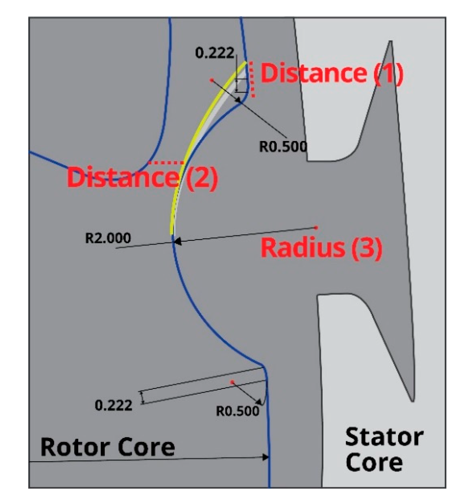
According to the previous discussion, new parameters were set to obtain a notch design to reduce the cogging torque and torque ripple, as shown in Figure 8. Distance (1) was fixed at 0.5 mm, and it is the distance from an end of the notch’s arc, when its radius (3) is 2 mm. Distance (1) was fixed to observe the analysis result of torque and torque ripple with the width difference. The changes in radius (3) were analyzed according to changes in notch depth, and not the width, and distance (2) indicates the distance from the magnet barrier to the notch, and it was measured because it is related to the flow of the magnetic flux.
Table 4 lists the values of distance (2) when distance (1) was fixed at 0.5 mm and radius (3) was changed.
To obtain the results shown in Figure 9, distance (1) was fixed at 0.5 mm, and a comparative analysis was performed on the cogging torque. The cogging torque was 3.7 N m at a distance (2) of 0.5 mm and a radius of 2.1 mm. At the deepest point, the cogging torque was 4.29 N m, which indicates a difference of 0.59 N m.
Figure 10 shows the results of analysis of the torque ripple according to radius (2) for various current phase angles. When the current phase angle was 0°, 10°, or 20°, the torque ripple was large if radius (2) was small. However, when the current phase angle was controlled to be 30° or 40°, the torque ripple tended to decrease as radius (2) decreased.
4. Discussion
In this study, a finite element method was used to analyze the properties of interior permanent magnet synchronous motors that are used as drive motors in electric cars. The external diameters of the stator and the rotor were set to be the same in order to compare various parameters such as the cogging torque, torque ripple, and back electromotive force voltage according to the position of a notch on the rotor shape. In the electromagnetic field analysis, the input voltage and input current were set to be the same. The motor’s performance characteristics were analyzed according to the notch position on the rotor shape.
The aim of this work was to determine an approach to obtain the design a rotor shape that can minimize the cogging torque and torque ripple so that a low-noise drive motor can be designed. The application target was an IPM motor; thus, current phase angle control was required to ensure that various characteristics of the motor, such as efficiency, power, and torque, do not degrade. Therefore, the point with the maximum torque was found via phase angle control, and the torque ripple, cogging torque, and maximum power were determined.
First, the notch position on the rotor shape was analyzed. Notches can be placed in a variety of positions, and thus, to determine the optimum position, notches were placed in five locations on the rotor and a comparative analysis of the resulting characteristics was performed. The results confirmed that placing the notches on the outer part of the magnet produced the best properties, and this design was then further optimized to obtain the best possible design.
Next, in the design phase, the distance between the rotor and the magnet barrier was fixed, and the original size of the notch was changed. When the overall analysis results were considered, V-shape (a) was found to be the most suitable notch shape in terms of reducing the noise and vibration, owing to the low values of the configuration’s torque ripple and cogging torque in the analysis in which distance (1) was 1 mm.
This paper proposed a notch shape optimization method for reducing the vibration and noise in vehicles. Vibration and noise are considered to be particularly important factors in electric cars. Luxury cars experience many problems pertaining to vibration and noise, and these factors can be reduced by designing the drive module via the proposed method. The proposed method can be widely used in the design of electric car drive motors to ensure an appropriate noise level.
Author Contributions
Conceptualization, M.-H.H. and H.-S.L.; Data curation, M.-H.H.; Formal analysis, M.-H.H.; Methodology, H.-S.L.; Supervision, H.-R.C.; Validation, H.-S.L.; Visualization, M.-H.H.; Writing—original draft, M.-H.H. and H.-S.L.; Writing—review and editing, H.-R.C.
Funding
This research was funded by the support of the Korea Institute of Industrial Technology as “Variable Architecture Powertrain Platform and Self-driving Factor Technology Development for Industrial EV Self-driving Vehicle” KITECH EO-18-0020.
Conflicts of Interest
The authors declare no conflicts of interest.
References
- Miller, T.J.E. Design of Brushless Permanent Magnet Motor; Clarendon Press: Oxford, UK, 1994. [Google Scholar]
- Pyrhonen, O.; Niemela, M.; Pyrhonen, J.; Kaukonen, J. Excitation control of DTC controlled salient pole synchronous motor in field weakening range. In Proceedings of the 5th International Workshop Advanced Motion Control (AMC), Coimbra, Portugal, 29 June–1 July 1998; pp. 294–298. [Google Scholar]
- Aihara, T.; Toba, A.; Yanase, T.; Mashimo, A.; Endo, K. Sensorless torque control of salient-pole synchronous motor at zero-speed operation. IEEE Trans. Power Electron. 1999, 14, 202–208. [Google Scholar] [CrossRef]
- Ko, H.S.; Kim, K.J. Characterization of Noise and Vibration Sources in Interior Permanent-Magnet Brushless DC Motors. IEEE Trans. Magn. 2004, 40, 3482–3489. [Google Scholar] [CrossRef]
- Hosinger, V.B. Performance of Polyphase Permanent Magnet AC Motor. IEEE Trans. Power Appar. Syst. 1980, 99, 1510–1518. [Google Scholar] [CrossRef]
- Sitapati, K.; Krishnan, R. Performance Comparisons of Radial and Axial Field, Permanent-Magnet, Brushless Machines. Proc. IEEE Ind. Appl. 2001, 37, 1219–1226. [Google Scholar] [CrossRef]
- Hwang, S.M.; Eom, J.B.; Jung, Y.H.; Lee, D.W.; Kang, B.S. Various design techniques to reduce cogging torque by controlling energy variation in permanent magnet motors. IEEE Trans. Magn. 2001, 37, 2806–2809. [Google Scholar] [CrossRef]
- Mi, C.; Filippa, M.; Liu, W.; Ma, R. Analytical method for prediction the air-gap flux of interior-type permanent magnet machine. IEEE Trans. Magn. 2004, 4, 50–58. [Google Scholar] [CrossRef]
- Im, C.Y.; Son, J.W.; Jung, S.Y. Characteristic Analysis of Interior Permanent Magnet Synchronous Motor for Electric Vehicles Propulsion with High-Speed Operation; The Korean Institute of Electrical Engineers: Seoul, Korea, 2011; pp. 97–99. [Google Scholar]
- Jin, Y.S.; Cho, K.Y.; Kim, H.W.; Lim, B.K.; Han, B.M. Torque ripple reduction based on flux linkage harmonics observer for an interior PM synchronous motor including back EMF harmonics. Trans. Korean Inst. Power Electron. 2013, 18, 367–375. [Google Scholar] [CrossRef]
- Lee, S.H.; Hong, I.P.; Park, S.J.; Kim, C.U. Torque ripple minimization for IPMSM with non-sinusoidal back-EMF. Trans. Korean Inst. Power Electron. 2002, 7, 91–100. [Google Scholar]
- Lee, D.H.; Kim, C.H.; Kwon, Y.A. Reduction of torque ripple of PMSM using iterative flux estimation. Trans. Korean Inst. Power Electron. 2001, 6, 346–350. [Google Scholar]
- Hwang, S.M.; Eom, J.B.; Hwang, G.B.; Jeong, W.B.; Jung, Y.H. Cogging torque and acoustic noise reduction in permanent magnet motors by teeth paring. IEEE Trans. Magn. 2000, 36, 3144–3146. [Google Scholar] [CrossRef]
- De la Ree, J.; Boules, N. Torque production impermanent-magnet synchronous motors. IEEE Trans. Ind. Appl. 1989, 25, 107–112. [Google Scholar] [CrossRef]
- Kwon, S.O.; Lee, J.J.; Lee, G.H.; Hong, J.P. Torque ripple reduction for permanent magnet synchronous motor using harmonic current injection. Trans. Korean Inst. Power Electron. 2009, 58, 1930–1935. [Google Scholar]
- Chen, S.; Song, A.; Sekiguchi, T. High efficiency and low torque ripple control of permanent magnet synchronous motor based on the current tracking vector of electromotive force. Conf. Rec. IEEE Ind. Appl. Soc. 2000, 3, 1725–1729. [Google Scholar] [CrossRef]
- Yang, Y.; Castano, S.; Yang, R.; Kasprzak, M.; Bilgin, B.; Sathyan, A.; Dadkhah, H.; Emadi, A. Design and Comparison of Interior Permanent Magnet Motor Topologies for Traction Application. IEEE Trans. Transp. Electr. 2017, 3, 4–9. [Google Scholar] [CrossRef]
- Kwak, J.; Min, S.; Hong, J.P. Optimal Stator Design of Interior Permanent Magnet Motor to Reduce Torque Ripple Using Level Set Method. IEEE Trans. Magn. 2010, 46, 2108–2111. [Google Scholar] [CrossRef]
- Lee, S.H.; Hong, J.P.; Hwang, S.M. Optimal Design for Noise Reduction in Interior Permanent-Magnet Motor. IEEE Trans. Ind. Appl. 2009, 45, 1945–1960. [Google Scholar]
- Kioumarsi, A.; Moallem, M.; Fahimi, B. Mitigation of Torque Ripple in Interior Permanent Magnet Motors by Optimal Shape Design. IEEE Trans. Magn. 2006, 42, 3706–3711. [Google Scholar] [CrossRef]
- Markovic, M.; Jufer, M.; Perriard, Y. Determination of tooth cogging for hard-disk Brushless DC motor. IEEE Trans. Magn. 2005, 41, 4421–4426. [Google Scholar] [CrossRef]
- Lee, J.; Bae, J.; Oh, S.-Y.; Kim, S.-J. Optimal design of a Magnetization Fixture for Cogging Torque Reduction of ODD Spindle Motor. In Proceedings of the 31st International Telecommunications Energy Conference, Incheon, Korea, 18–22 October 2009; pp. 1–3. [Google Scholar]
- Zhu, Z.Q.; Howe, D. Analytical prediction of the cogging torque in radial-field permanent magnet brushless motors. IEEE Trans. Magn. 1992, 28, 1371–1374. [Google Scholar] [CrossRef]
- Kurnia, A.; de Larminat, R.; Desmond, P.; O’Gorman, T. A low torque ripple PMSM drive for EPS applications. In Proceedings of the Nineteenth Annual IEEE Applied Power Electronics Conference & Exposition (APEC), Anaheim, CA, USA, 22–26 February 2004; Volume 2, pp. 1130–1136. [Google Scholar]
- Tamura, H.; Ajima, T.; Noto, Y. A torque ripple reduction method by current sensor offset error compensation. In Proceedings of the 15th European conference on Power Electronics and Application (EPE), Lille, France, 2–6 September 2013; pp. 1–10. [Google Scholar]
- Cho, K.Y.; Lee, Y.K.; Mok, H.S.; Kim, H.W. Torque ripple reduction of a PM synchronous motor for electric power steering using a low resolution position sensor. J. Power Electron. 2010, 10, 709–716. [Google Scholar] [CrossRef]
- Yoon, D.Y.; Hong, S.C. Reduction of torque ripple due to current-sensing errors in inverter-fed AC motor systems. Trans. Korean Inst. Power Electron. 1998, 3, 211–217. [Google Scholar]
Figure 1.
Slot stator and 8-pole rotor core: (a) stator core; (b) rotor core.
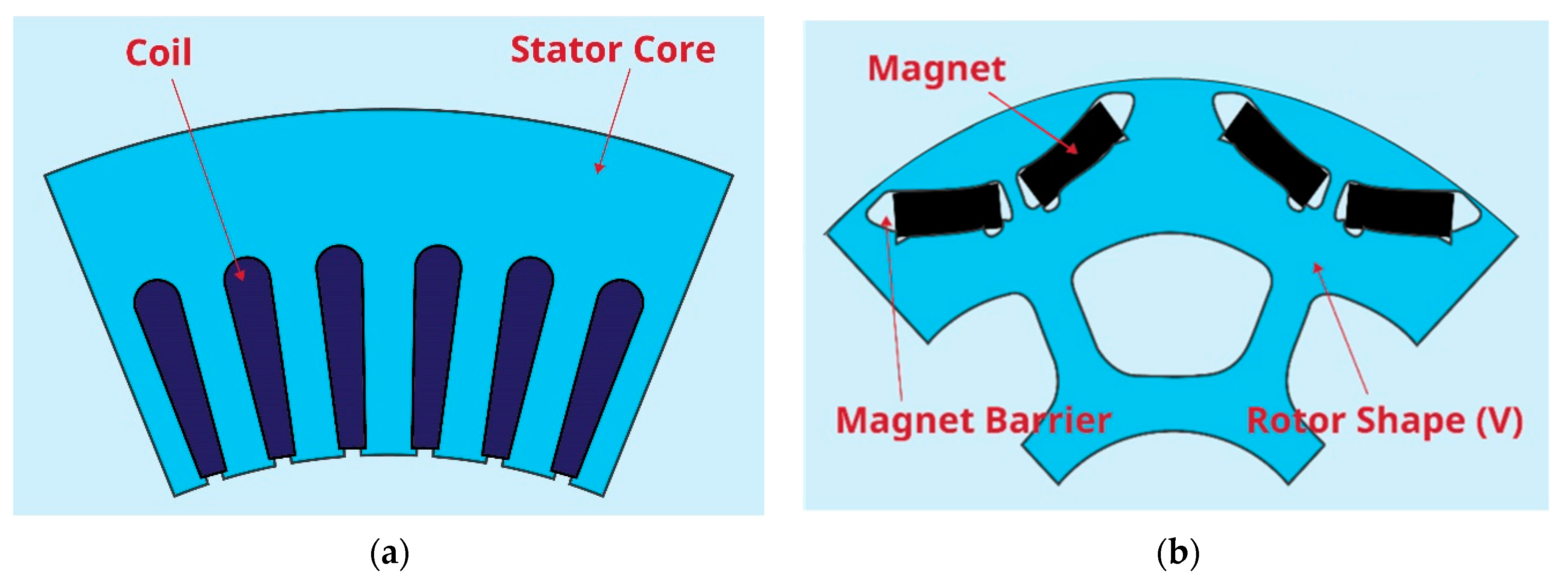
Figure 2.
Motor rotor notch design positions: (a) magnet’s inner notches; (b) magnet’s outer notches; (c) magnet’s central notches; (d) magnet’s additional central notches; (e) no notches (basic form).
Figure 2.
Motor rotor notch design positions: (a) magnet’s inner notches; (b) magnet’s outer notches; (c) magnet’s central notches; (d) magnet’s additional central notches; (e) no notches (basic form).
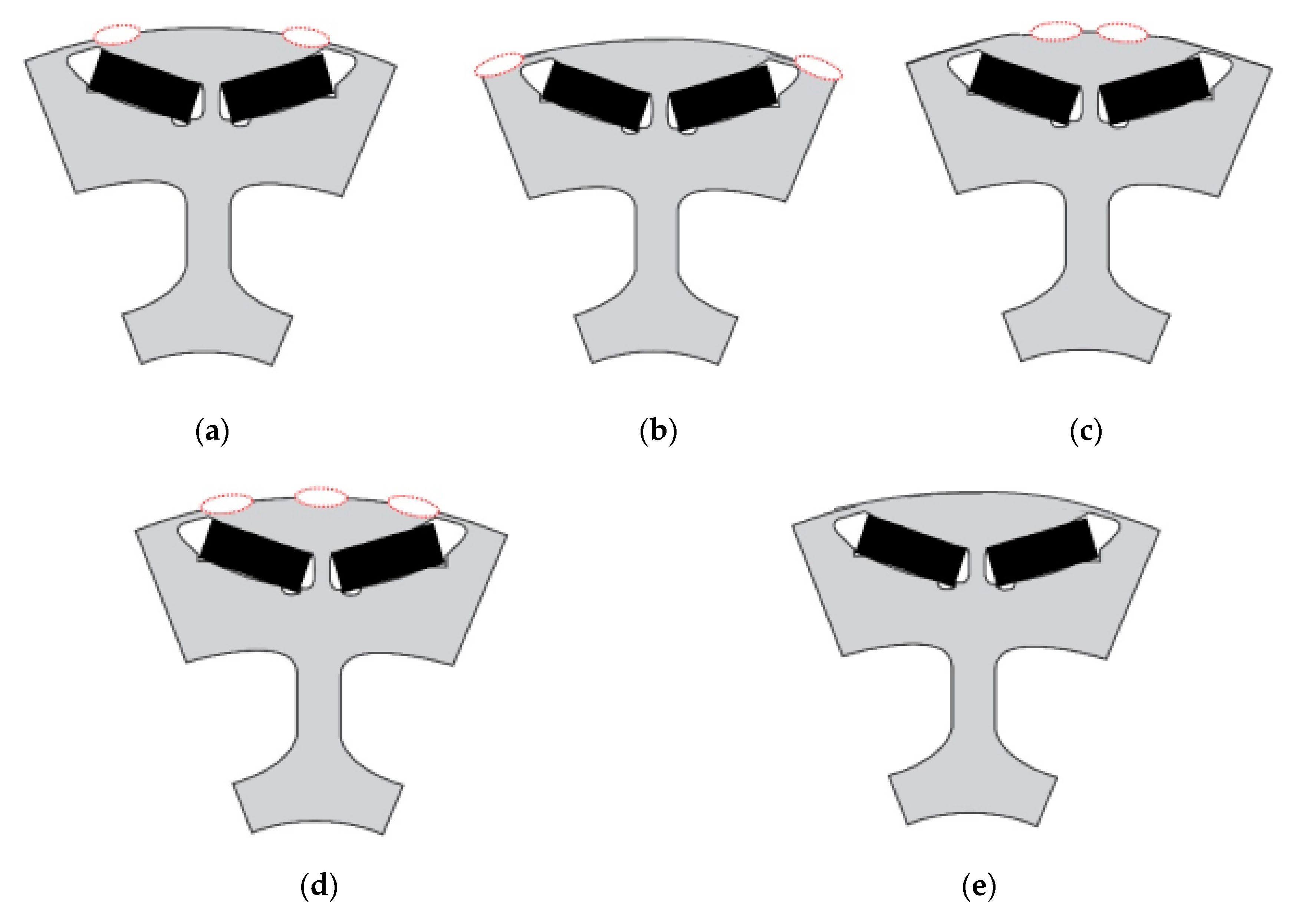
Figure 3.
Back electromotive force voltage, cogging torque, and torque ripple according to notch position: (a) back electromotive force voltage; (b) cogging torque; (c) comparative analysis of torque ripple.
Figure 3.
Back electromotive force voltage, cogging torque, and torque ripple according to notch position: (a) back electromotive force voltage; (b) cogging torque; (c) comparative analysis of torque ripple.
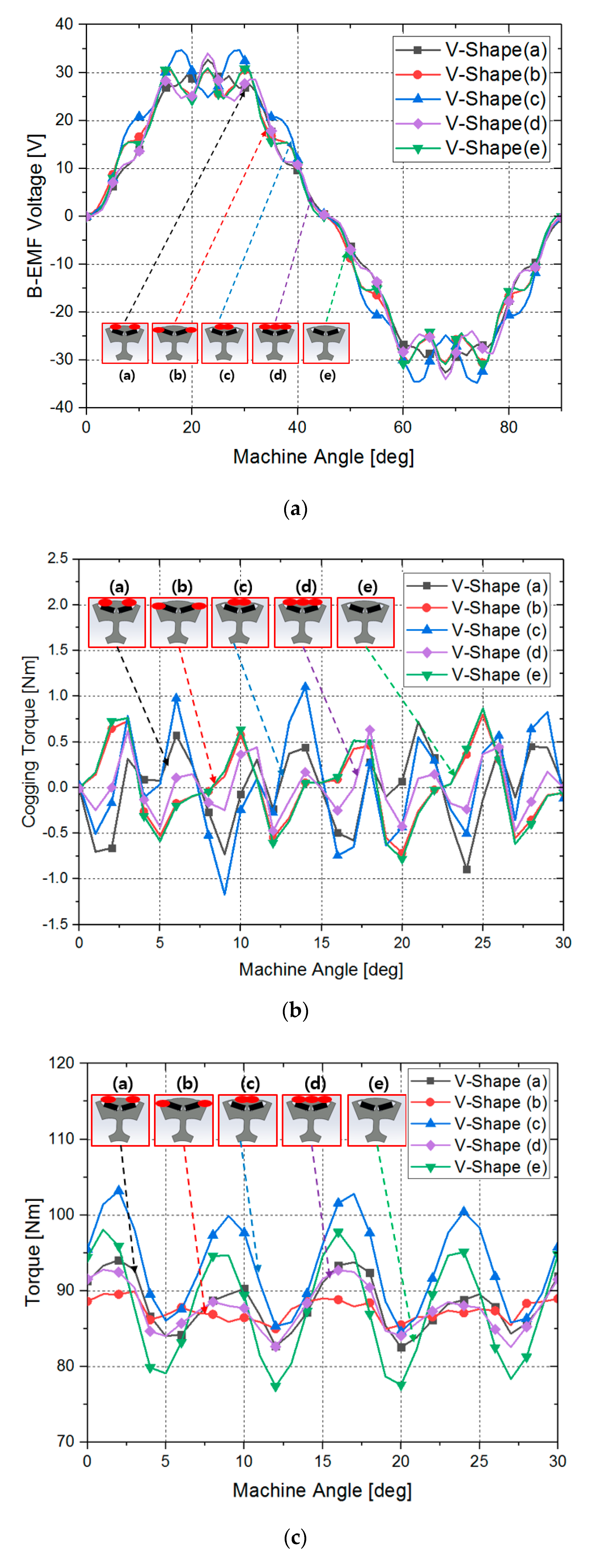
Figure 4.
Notch shape optimization: (a) notch optimization position; (b) notch optimization diagram.
Figure 4.
Notch shape optimization: (a) notch optimization position; (b) notch optimization diagram.
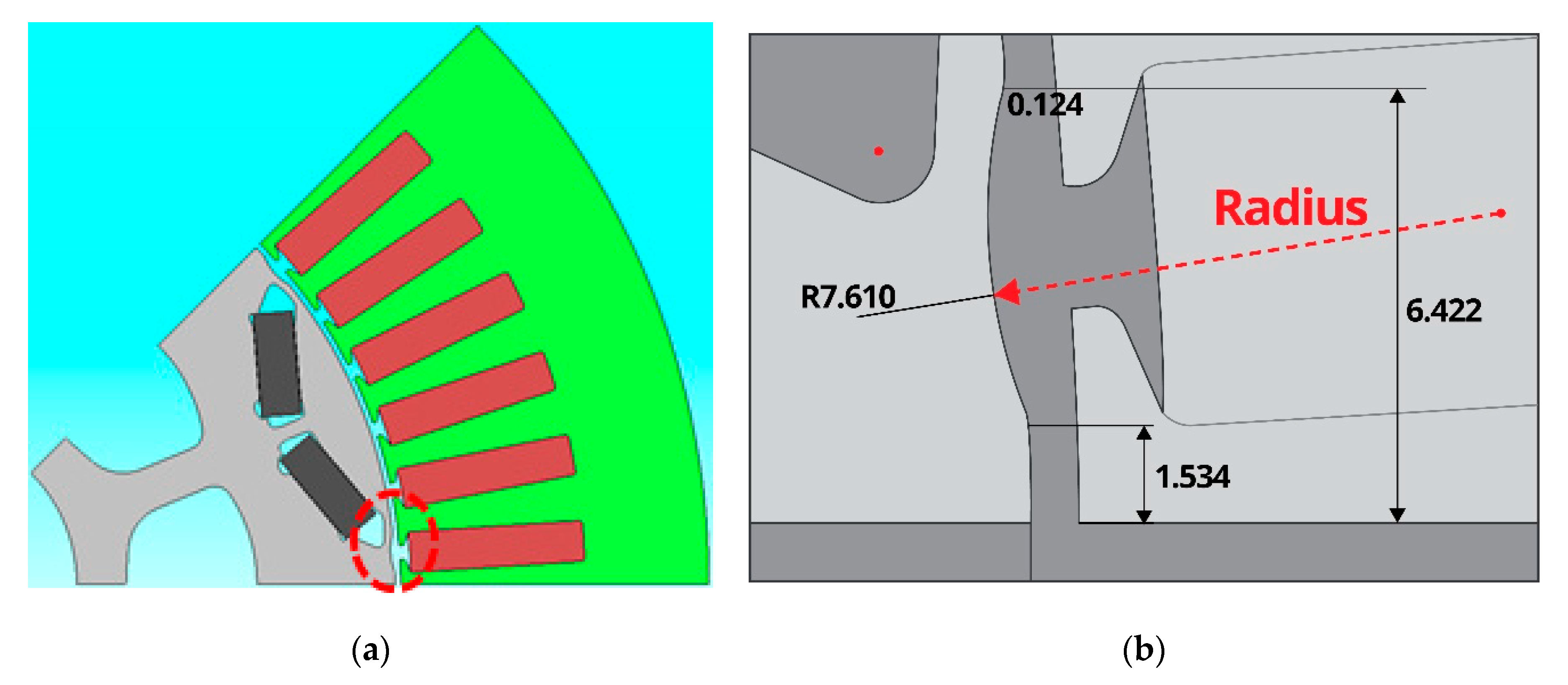
Figure 5.
Comparison of cogging torque according to notch radius.

Figure 6.
Comparative analysis of torque ripple according to notch radius.
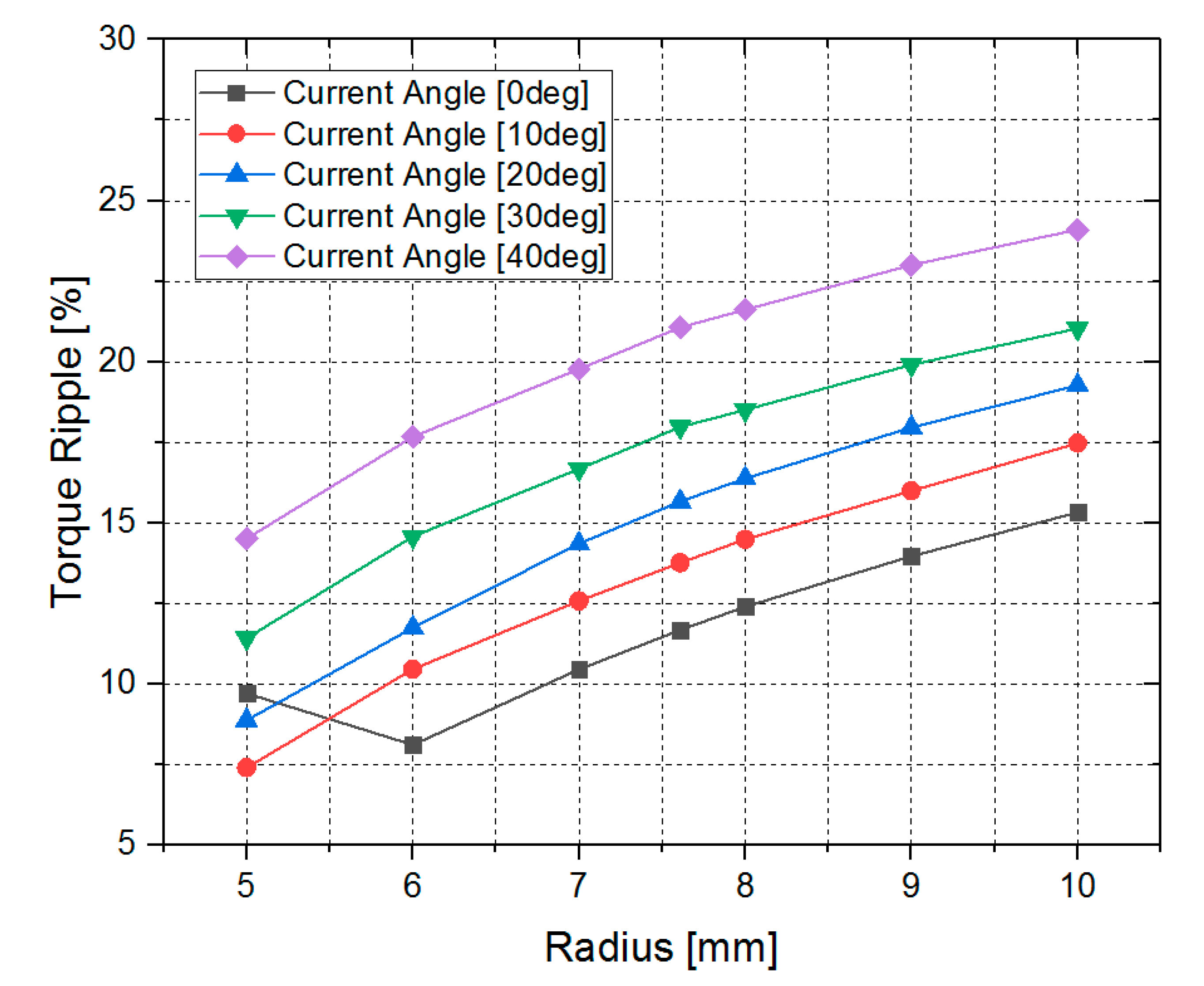
Figure 7.
Comparative analysis of torque according to notch radius.
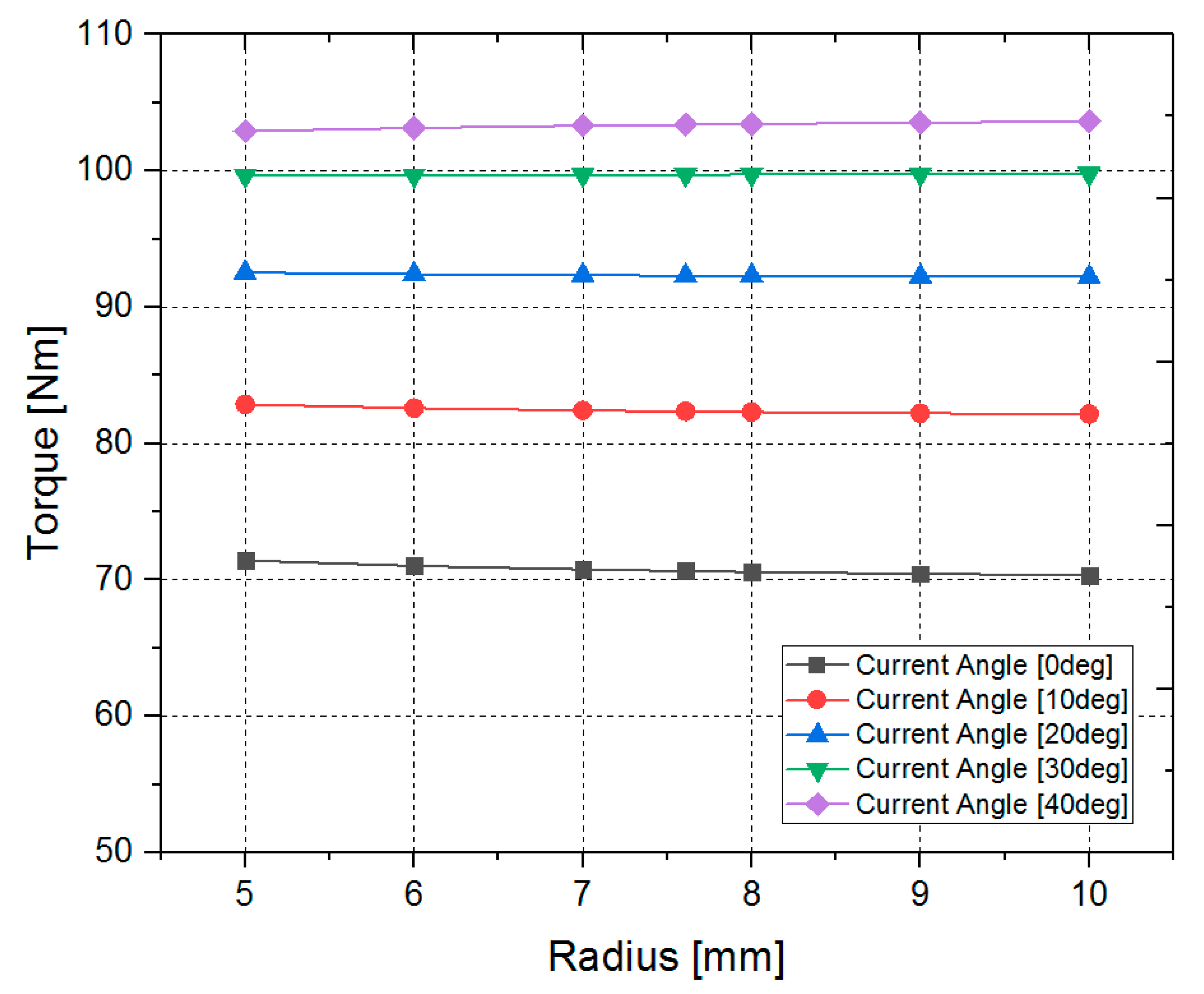
Figure 8.
Notch optimization diagram with length parameter.

Figure 9.
Comparative analysis of cogging torque when notch shape distance (1) is 0.5 mm.
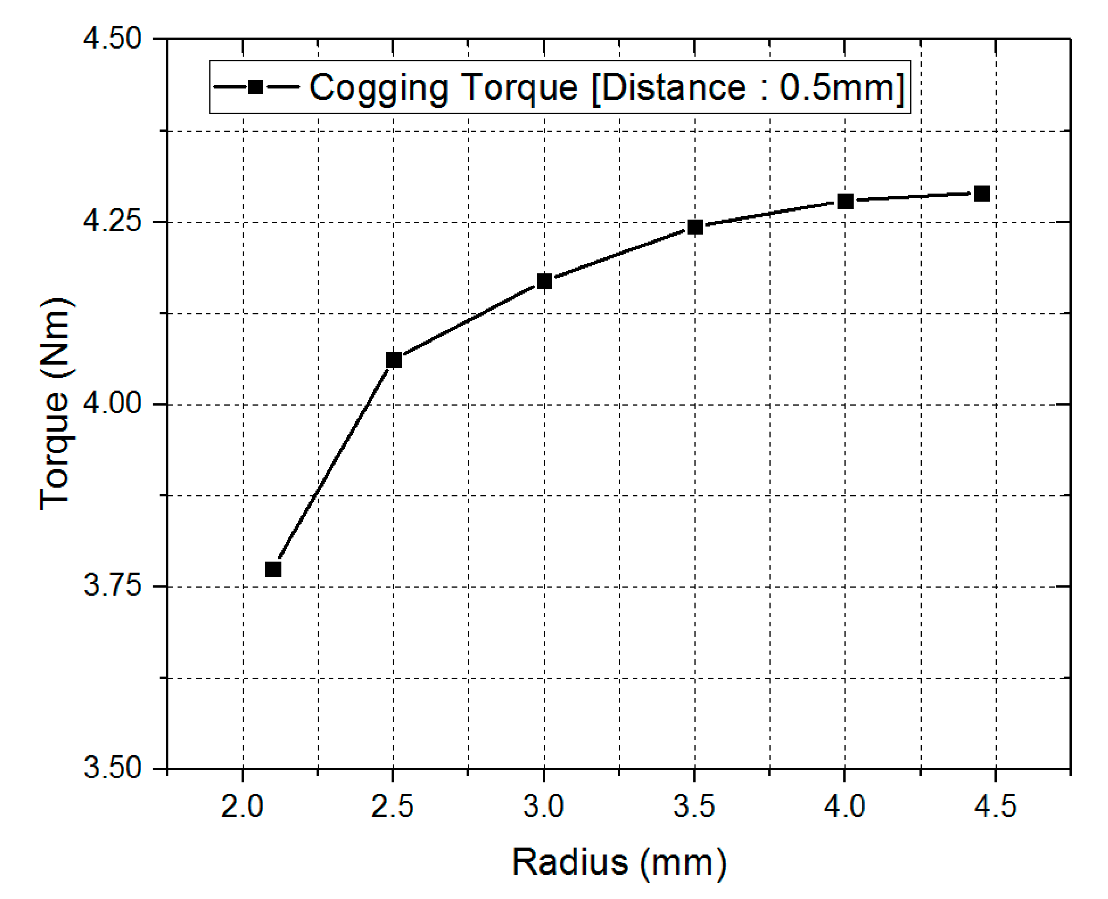
Figure 10.
Comparative analysis of torque ripple when notch shape distance (1) is 0.5 mm.


Table 1.
Interior permanent magnet synchronous motor (IPMSM) basic specifications.
| Parameters | Unit | Value |
|---|---|---|
| Number of Slots | EA | 48 |
| Number of poles | EA | 8 |
| Capacity | kW | 35 |
| Rated Speed | rpm | 10,000–11,000 |
| Outside Diameter | mm | 200 |
| Inside Diameter | mm | 122 |
| Stack Length | mm | 50 |
| Air Gap | mm | 0.7 |
Table 2.
Comparative analysis of cogging torque and torque ripple according to notch position.
| Characteristic | V-Shape (a) | V-Shape (b) | V-Shape (c) | V-Shape (d) | V-Shape (e) |
|---|---|---|---|---|---|
| B-EMF Voltage [V_rms] | 20.68 | 20.87 | 23.03 | 26.45 | 24.08 |
| Cogging Torque [Nm] | 1.7 | 1.73 | 2.6 | 1.21 | 1.882 |
| Torque [Nm] | 88 | 87 | 93 | 87.66 | 87.62 |
| Torque Ripple [%] | 15.9 | 8.04 | 22.58 | 12.9 | 24.41 |
| Power [kW] | 36.86 | 36.44 | 38.95 | 36.71 | 36.70 |
Table 3.
Rotor notch radius parameter.
| Analysis Case | Width [mm] | Radius(2) [mm] |
|---|---|---|
| 1 | 0.75 | 5 |
| 2 | 0.82 | 6 |
| 3 | 0.9 | 7 |
| 4 | 0.93 | 7.61 |
| 5 | 0.94 | 8 |
| 6 | 0.96 | 9 |
| 7 | 0.98 | 10 |
Table 4.
Changes in distance (2) and radius (3) when distance (1) is fixed at 0.5 mm.
| Distance (2) [mm] | Radius (3) [mm] | |
|---|---|---|
| 1 | 0.5 | 2.1 |
| 2 | 0.78 | 2.5 |
| 3 | 0.93 | 3.1 |
| 4 | 1 | 3.5 |
| 5 | 1 | 4 |
| 6 | 1.05 | 4.451 |
© 2018 by the authors. Licensee MDPI, Basel, Switzerland. This article is an open access article distributed under the terms and conditions of the Creative Commons Attribution (CC BY) license (http://creativecommons.org/licenses/by/4.0/).
Share and Cite
MDPI and ACS Style
Hwang, M.-H.; Lee, H.-S.; Cha, H.-R. Analysis of Torque Ripple and Cogging Torque Reduction in Electric Vehicle Traction Platform Applying Rotor Notched Design. Energies 2018, 11, 3053. https://doi.org/10.3390/en11113053
AMA Style
Hwang M-H, Lee H-S, Cha H-R. Analysis of Torque Ripple and Cogging Torque Reduction in Electric Vehicle Traction Platform Applying Rotor Notched Design. Energies. 2018; 11(11):3053. https://doi.org/10.3390/en11113053
Chicago/Turabian StyleHwang, Myeong-Hwan, Hae-Sol Lee, and Hyun-Rok Cha. 2018. "Analysis of Torque Ripple and Cogging Torque Reduction in Electric Vehicle Traction Platform Applying Rotor Notched Design" Energies 11, no. 11: 3053. https://doi.org/10.3390/en11113053
Note that from the first issue of 2016, this journal uses article numbers instead of page numbers. See further details here.