Technical Note

Atomization of Gel Fuels with Solid Particle Addition Utilizing an Air Atomizing Nozzle

1
Science and Technology on Scramjet Laboratory, National University of Defense Technology, Changsha 410073, China
2
Department of Apllied Mechanics, National University of Defense Technology, Changsha 410073, China
*
Author to whom correspondence should be addressed.
Energies 2018, 11(11), 2959; https://doi.org/10.3390/en11112959
Submission received: 17 October 2018 / Revised: 27 October 2018 / Accepted: 29 October 2018 / Published: 30 October 2018

Abstract

:
Microscopic high-speed imaging is used to experimentally measure the velocity and size of droplets of gelled RP-1 based fuels with a solid particle additive. The gels are atomized using an air atomizing nozzle. The droplet diameter and velocity at a fixed position 20 cm from the nozzle on the centerline of the spray are measured at air mass flow rates of 1.5, 3 and 5 g/s. A parametric study is conducted to study the effect of gas mass flow rate, boron particle content, and species of the solid particle on the droplet characteristics. The results indicate that the droplet size decreases with the increasing of gas mass flow rate and boron particle content. Gel fuels with an aluminum particle are observed to produce smaller droplets at a low gas mass flow rate than that with a boron particle. The implication of these observations is that the atomization processes for gelled fuels with an additive of solid particles is controlled by the velocity difference between the gas and the droplets.

1. Introduction

The demand for high energy density and improved safety fuels have led to an ever increasing research of gel fuels [1], which are interesting candidates for these broadened requirements both in the range of rocket and ramjet engines [2]. Gel fuels are liquid fuels and oxidizers whose rheological properties have been altered by the addition of gelling agents, therefore behaving as non-Newtonian fluids [3,4]. The unique viscoelastic properties of the gelled fuels enable them to be stored as solids, preventing leaks, but flow as liquids under certain pressure. The addition of gelling agents constructs a new microstructure, which can prevent aggregation and separation of the solid phase. Energetic solid particles such as aluminum, boron, magnesium, etc. can be appended to improve the theoretical performance. To achieve high combustion efficiency, fine atomization is necessary [5]. The atomization of gelled fuels is essentially different from the atomization of Newtonian liquids, yet very little is known about the influence of the energetic solid additives on atomization.
When the gel fuels are applied in a ramjet or a rocket engine with a low boiling point propellant, such as liquid oxygen, the twin-fluid atomizer or air-blast injector can provide a comparatively finer degree of atomization for a given flow capacity and supplied pressures [6,7]. Green et al. [8] conducted an experimental investigation to compare the atomization characteristics of gelled and non-gelled propellant simulants in an air-blast triplet injector and a coaxial injector. A simulant gelled propellant composed of water, sodium hydroxide, and an acrylic acid polymer resin was used to simulate the viscosity of the aluminum/RP-l metallized gelled fuel. Due to the high viscosity, the gelled liquid sprays yielded coarser atomization than the non-gelled liquid sprays. The authors also indicated that atomization was improved as the liquid mass flow rate increased at a constant gas mass flow rate. Ciezki et al. [9] investigated the air-blast atomization of the kerosene-based gelled fuels using different gelling agents. They also found that the gelled fuels were more difficult to be atomized than the counterpart of Newtonian fuels.
Rahimi and Natan [10] used an impinging air-blast triplet injector with a central converging gel orifice to atomize the gelled fuel and a Malvern Mastersizer X was used to measure the size distribution of the droplets. They found that the Sauter mean diameter (SMD) decreases down to a minimum constant value with the increase of the air-to-liquid mass flow rate ratio (ALR) and a correlation between SMD and ALR was found. Chernov and Natan [11] succeeded in reducing the spray SMD by introducing periodic disturbances at the exit plane of a triplet air-blast atomizer. The droplet size was found to decrease with increasing the frequency of the disturbances.
Baek et al. studied the spraying and atomization of slurry containing Carbopol gel and nanoparticles using impinging jets. The results showed that the breakup length of spray decreases with the addition of nanoparticles [12]. Kim et al. experimentally investigated the spray characteristics of a slurry-swirl spray made by mixing gel fuel and aluminum powder. They found that with the increase of particle content, the instability of the liquid film is attenuated by the increase in the liquid film thickness. When the particle size is sufficiently large, the breakup length is shorter than that of the small particles [13]. Jejurkar et al. visualized and quantitatively characterized the sheet atomization of a gelled propellant mixed with nanoparticles [14]. Two new regimes were discovered and characterized.
In the present experimental study, the atomization process of the metallized gel fuels is presented by using an air atomizing nozzle. An effort was made to measure the sizes and velocities of the droplets to investigate the effects of the particle content, the species of particles, and the gas flow rate on the atomization.

2. Experimental Setup and Data Processing Method

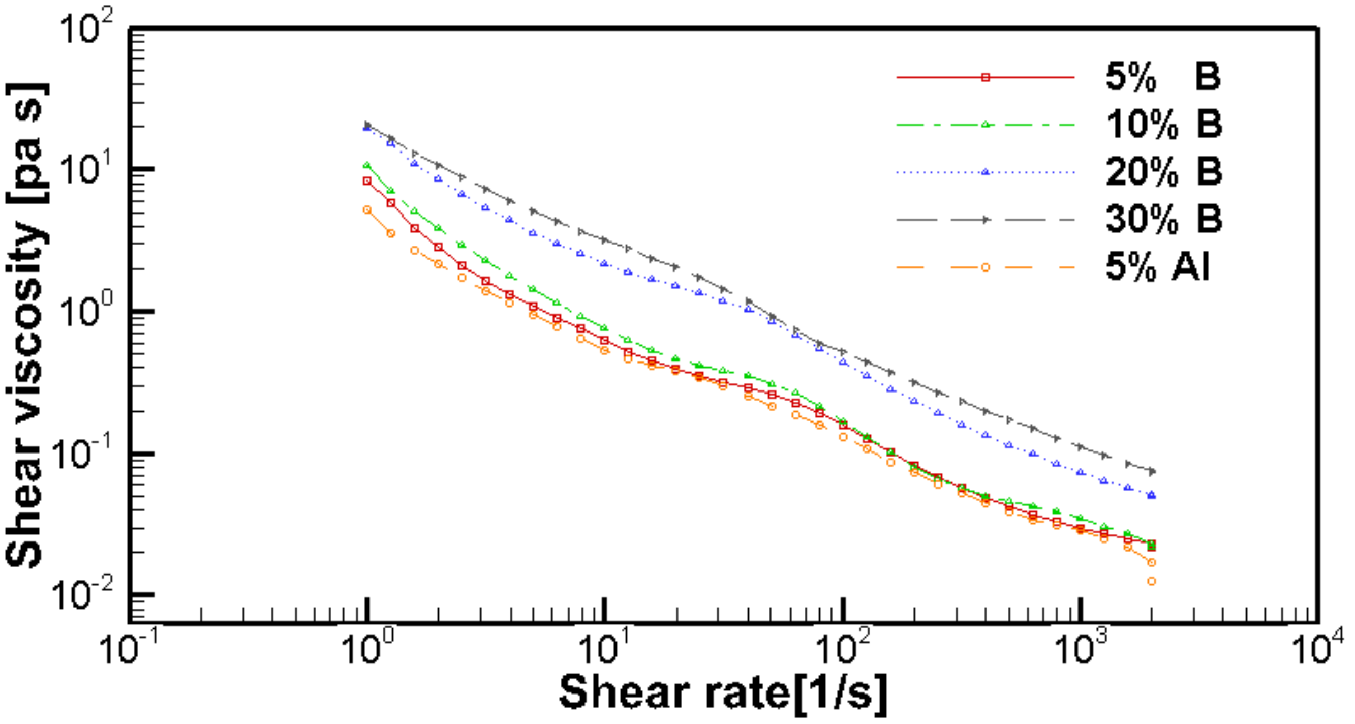
2.1. Gel Preparation and Characteristics

The kerosene-based gel fuels are formulated using a magnetic stirrer. The gellant is polyamide resin. The mixing procedure for the gel fuel requires the kerosene solution to be heated to 80 degrees Celsius. A vortex is generated using a stirrer, and solid particles and gelling agent are added in small amounts at a relatively slow addition rate. The solution is stirred for 4 to 6 h until it is determined to be homogeneous by visual inspection. In order to ensure uniform dispersion of particles, the gel fuels are fully stirred before each experiment.
The rheology of each gel fuel is measured with a rheometer (AR2000, TA Instruments Ltd., New Castle, DE, USA). The results show that the gel fuel is a shear-thinning fluid, which indicates that the shear viscosity decreases as the shear rate increases, as shown in Figure 1. The rheological behavior of a non-Newtonian shear-thinning fluid is typically described in the form of a power law equation (Equation (1)).
η = K γ ˙ n 1  
where η = apparent viscosity, Pa   s ; K = consistency, Pa   s n ; n = shear index; γ ˙ = shear rate, s−1.
Since this equation does not include the yield stress of the gel, rather than the expected limit of the minimum viscosity at very high shear rates, it is only suitable for experimental data in the medium shear rate range. Therefore, the rheological behavior of a non-Newtonian shear-thinning fluid is also described by the Herschel-Bulkle equation:
η = τ 0 γ ˙ + K γ ˙ n 1  
where τ 0 = yield stress, Pa.
The related power law and Herschel-Bulkley coefficients have been calculated by making use of the rheometer software and the results are listed in Table 1. It can be seen that all gels have a distinct yield stress. As the boron content increases, the yield stress and the pre-exponential factor K increase and the exponential factor n decreases, which shows that with increasing boron particle content, the viscosity will increase. This is in agreement with the conclusions of Kampen [15] where the gelled Jet A-1with aluminum particle addition was studied.

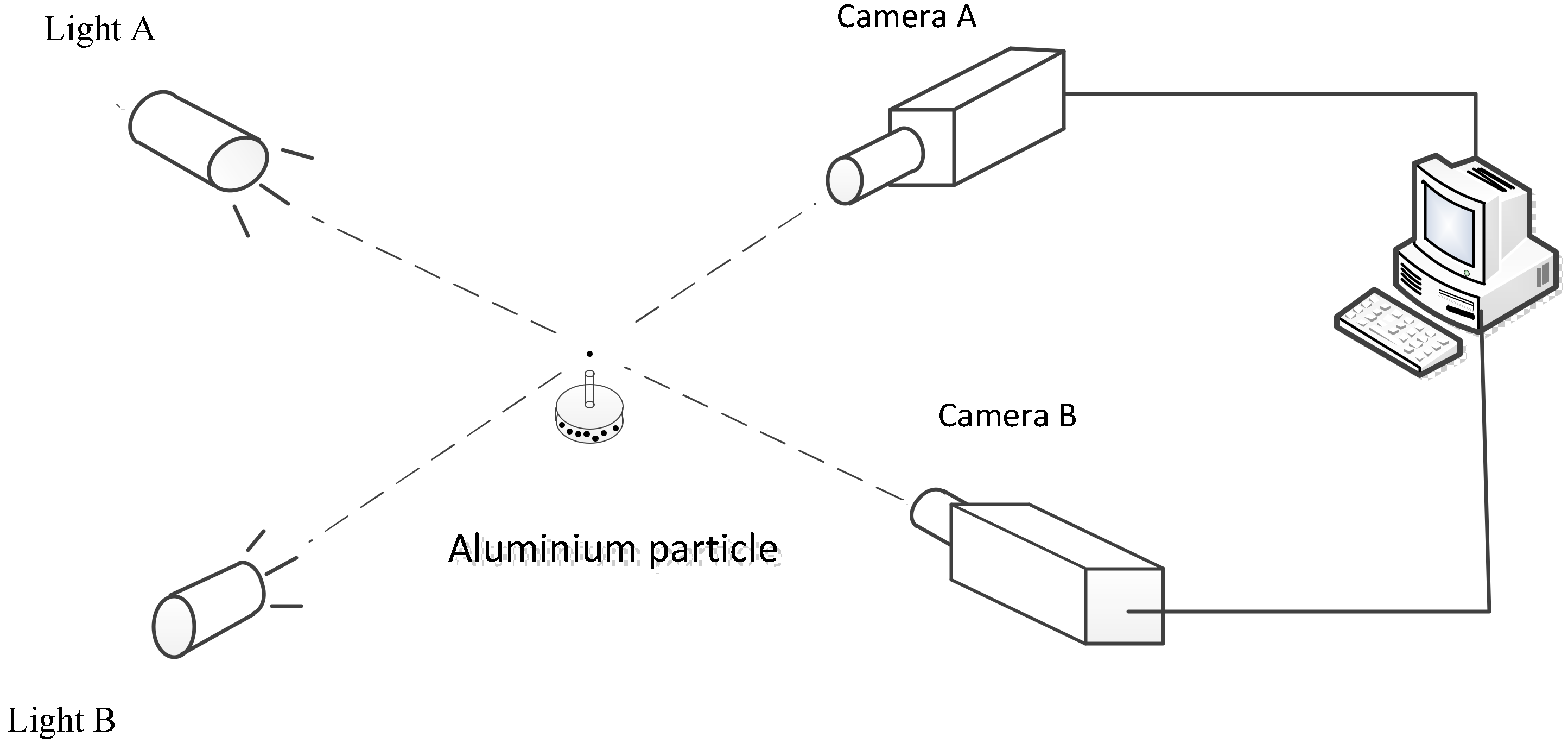
2.2. Experimental Setup

A general overview of the setup is shown in Figure 2. The experimental system includes the following parts: (1) a gel fuel feeding system, (2) a gas feeding system, (3) a high-speed camera, (4) a high mag zoom lens, and (5) an air atomizing nozzle. The gel fuel feeding system carries the fluid to the injector inlet. The fluid is stored in a cylinder (length 450 mm, diameter 63 mm, gross volume 1.4 L, maximum working pressure 160 bar) with a piston, which drives the fluid to flow toward the injector at constant velocity. The piston was driven by an electric motor. The mass flow rate is determined by the motor speed. The uncertainty in the mass flow rate measurements is less than 3.0%. The gaseous nitrogen is used as the atomizing gas. The nitrogen mass flow rate is measured by a gas turbine meter. The injector used in the test is a special industrial unit named an air atomizing nozzle and is shown in Figure 3. Air atomizing nozzles have been extensively studied in the literature. The droplets are broken by the shear of the high velocity annular jet [16]. Strizhak et al. conducted detailed studies of the process of droplet breakage in a gas stream [17,18,19].
The microscopic high-speed imaging technique has been applied for the visualization of the spray generated by the air atomizing nozzle. A high-speed camera (PCO.dimax, PCO AG, Kelheim, Germany) with a maximum resolution of 2016 × 2016 pixels was used in conjunction with a 200 W back LED light. A high mag zoom lens (magnifying lens 14×) is attached to the camera in order to capture the rapid movement of the droplets, and the depth of field of the lenses is 0.05 mm. The minimum exposure time of the camera is 1 microsecond. The image resolution is 2016 × 2016 pixels.

2.3. Data Processing Method

Before the spray test, a scale for the microscope is used to calibrate the pixel size. Figure 4 shows the scale of the image obtained by the high mag zoom lenses. The total length of the scale is 1 mm, divided into 100 equal portions with each division measuring 0.01 mm. Knowing the resolution and the scale of the image, the physical size of a pixel can be calculated. It is about 12.6 pixels per 0.01 mm in this condition. Figure 5 is an image of the spray. The thin lines in the figure are the tracks of the atomized droplets. The line width indicates the droplet diameter and the length of the line gives the moving distance of the droplets in the focal plane during the exposure time. After picking up all diameters of the droplets, the maximum drop diameter (Dmax) of the spray could be obtained. Dmax affects the combustion characteristics of the droplets [20] and the design of the combustion chamber.

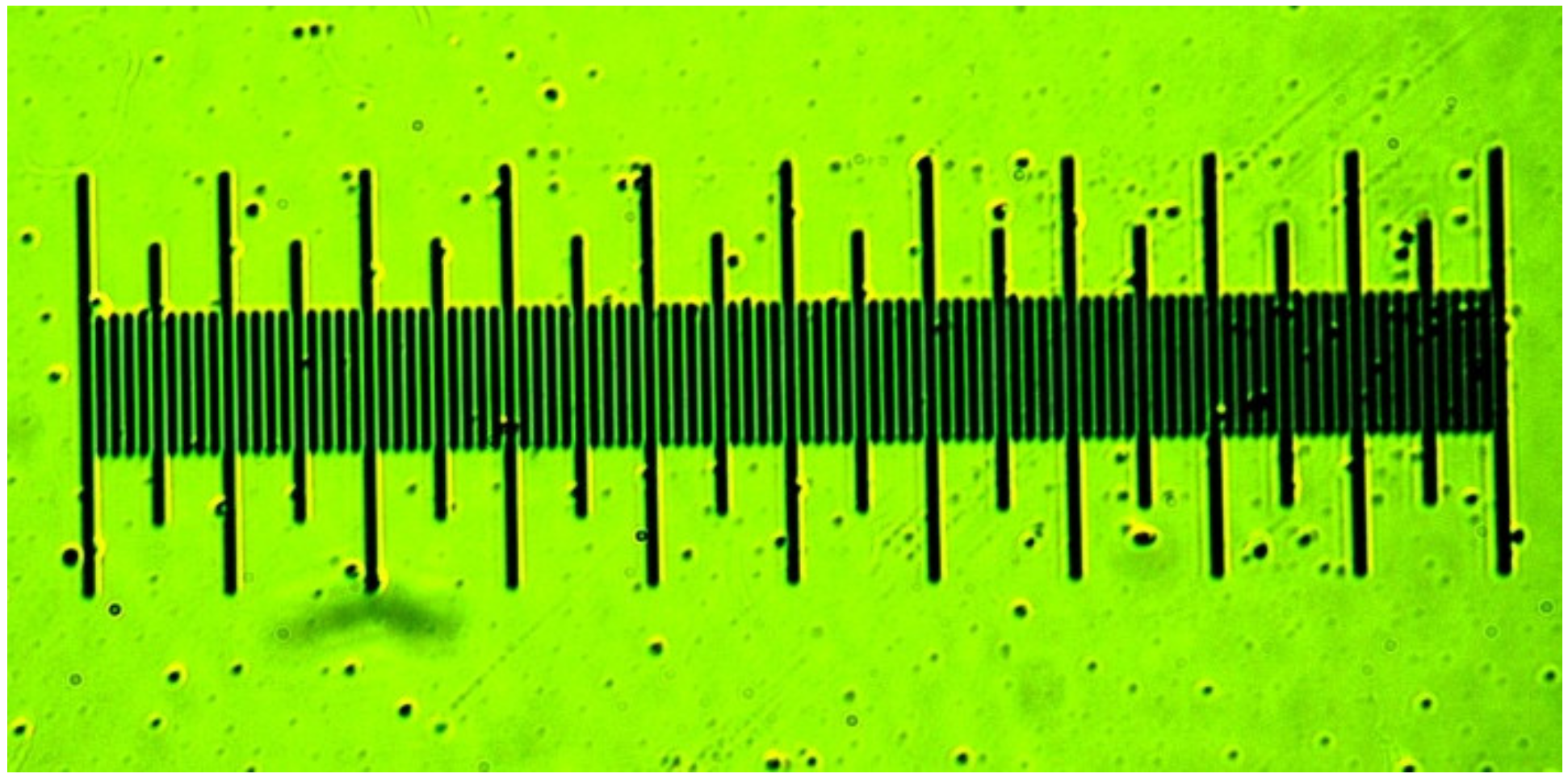
2.4. Calibration Experiment and Error Analysis.

A calibration experiment has been conducted to confirm the accuracy of this technique. The schematic of the experiment is shown in Figure 6. It consists of a particle segregator and two vertically arranged high-speed photography cameras. The frame rates of both cameras are 1000 fps. The exposure time for camera A and B are 25 and 400 ms, respectively. Figure 6 shows the images of the aluminum particle. The particle diameter measured in Figure 7a is 115.8 μm. The width of the streak in Figure 7b is 112 μm. The particle velocity calculated using the exposure time and line length in Figure 7b is 0.55 m/s. The particle velocity could be calculated from its moving distance in the two successive frames of camera A during the corresponding time delay. The resulting velocity is 0.57 m/s. The errors of the particle diameter and the velocity in the calibration experiment are 3.3% and 3.5%, respectively.

3. Results and Analysis

The sprays all have a very narrow cone angle (~20 degrees). All measurements are taken at the centerline of the spray at 20 cm below the nozzle outlet. This particular point is selected because of the ignition point in the subsequent experiment on the gel fuel ramjet combustor. At least 20 continuous pictures are collected for each test to achieve a statistical convergence. There are at least 20 droplets in each picture. The gel fuels atomized in the experiment are the gelled kerosene with boron particle addition and the gelled kerosene with aluminum particle addition. The mean diameters of both the boron and aluminum particle used in the experiment are 3 μm. The present study includes a parametric investigation to calculate the effects of the following parameters on the droplet size (Dmax) and the droplet velocity:
  • The gas mass flow rate.
  • The boron particle content.
  • The species of the solid particle.

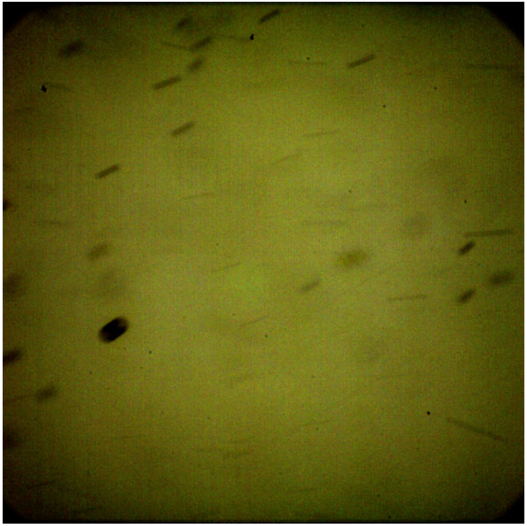
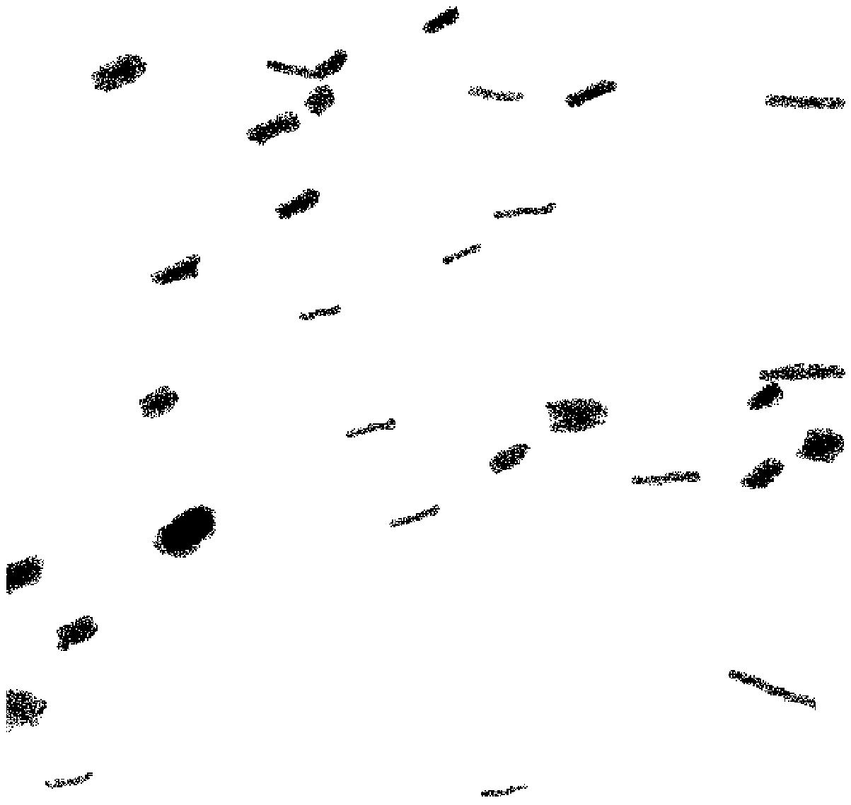
3.1. Analysis of the Spray

Figure 5 shows a typical picture of the gel fuel spray. After removing the background noise and pixel enhancement, we get Figure 8. There are 31 droplets in the picture. The actual physical size of the area of interest is 1.6 mm × 1.6 mm, and the depth of field of the picture is 0.05 mm. Due to the non-uniformity of the gas flow, the downward moving trend of the droplets is interrupted and deflected. The projection of the droplet velocity in the focal plane is from 3.3 m/s to 12.7 m/s in this image; as the small droplets can better follow the flow, the smaller droplets have the higher velocity. The largest and smallest droplets have diameters of 55 and 8 μm, respectively.

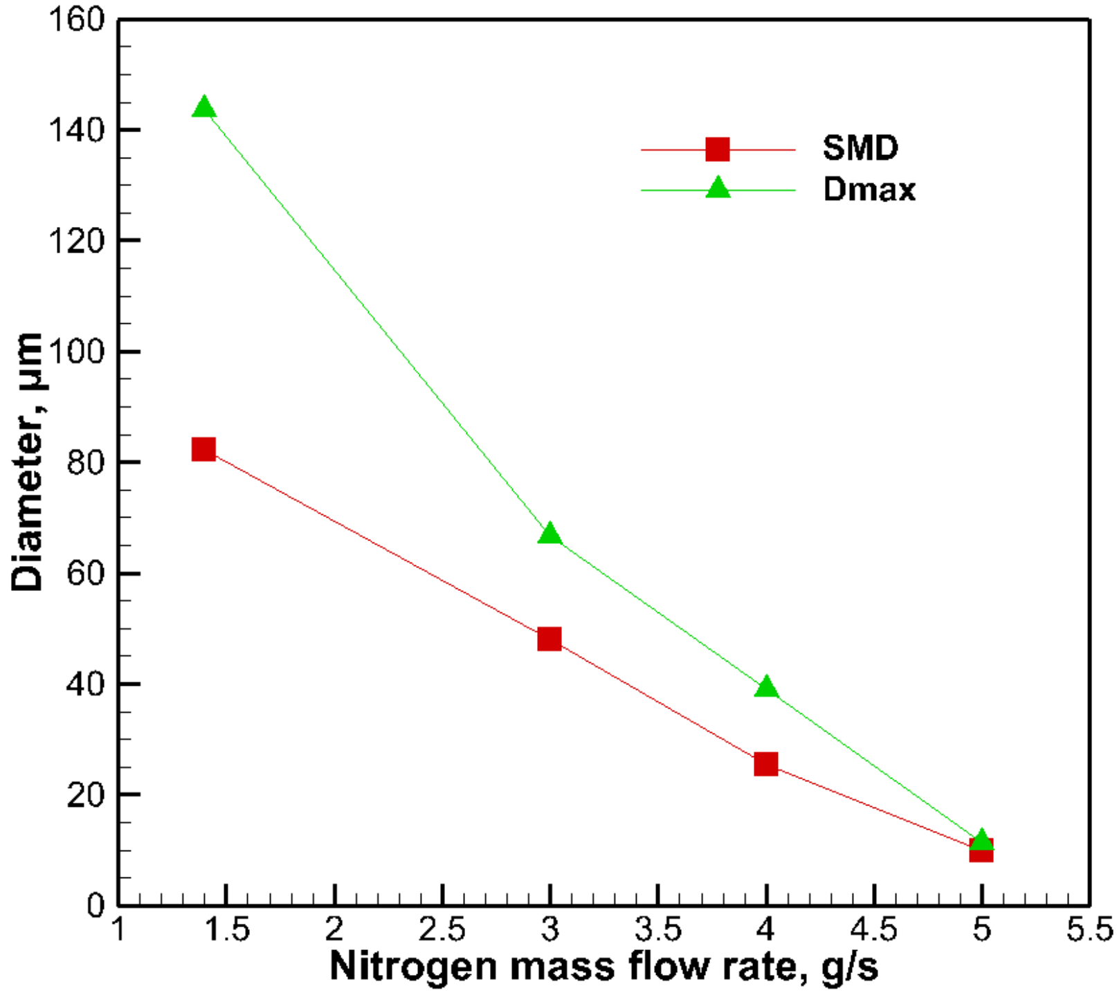
3.2. The Effect of Gas Mass Flow Rate on Droplet Size

Figure 9 shows the droplet diameter versus gas mass flow rate; the Sauter mean diameter (SMD) of the spray is calculated using all the diameters of the visible particles in the pictures. In general, for a constant gel mass flow rate, increasing the gas mass flow rate produces smaller droplets, and this is in agreement with the conclusions of Rahimi and Natan [10] for water gels with a triplet impinging air-blast atomizer. The SMD is close to Dmax and the high nitrogen mass flow rate indicates a more uniform atomization with a higher gas mass flow rate. However, in the image observation method, there are some tiny droplets that cannot be captured, so the calculated average diameter may deviate from the true average diameter. Dmax does not have this deviation, and as illustrated in Figure 9, the trends of Dmax and SMD are consistent, so Dmax is used to analyze the atomization process of the gel fuels with solid particle addition.

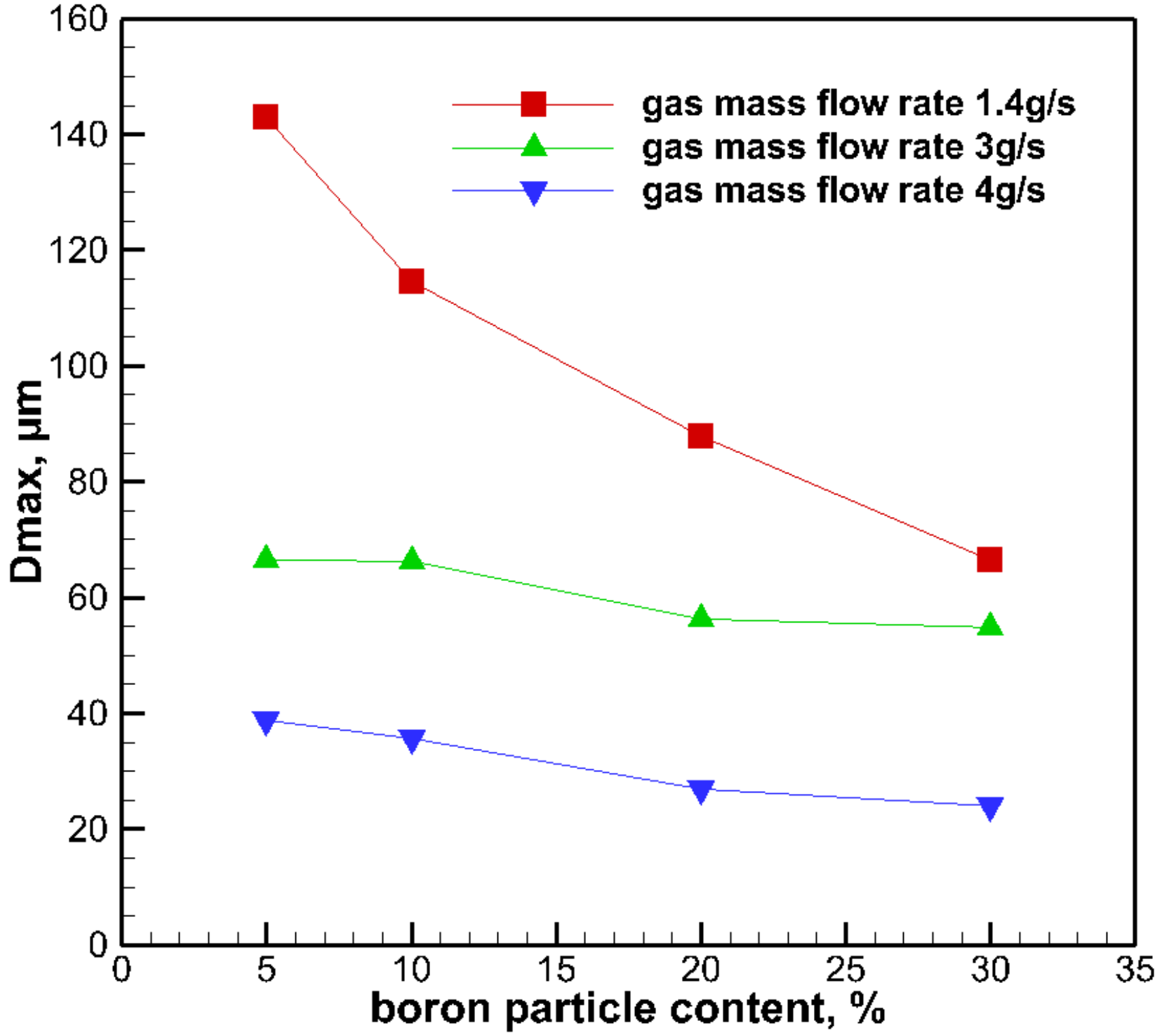
3.3. The Effect of Boron Particle Content on Droplet Size

A series of spray comparison tests are conducted using the baseline parameters of 3% gellant content and 10.6 g/s gel mass flow rate. The boron particle content of the gel fuels is 5%, 10%, 20% and 30%, respectively. Figure 10 provides the experimental data for Dmax at different boron particle contents. In general, increasing the particle content leads to the decreasing in droplet size. This is in agreement with the conclusions of Hecht [16] for pneumatic atomization of concentrated laundry detergent slurries. As illustrated in Figure 1, by increasing boron particle content, the viscosity will increase. The increase in viscosity is not conducive to atomization. In the present research, the gel fuel is sprayed using an air atomizing nozzle. The high-speed shearing action of the gas stream breaks the gel into small droplets. Due to the fact that the interface between the solid particles and the gel is easier to separate than the interface between the liquids inside the gel, higher particle content promotes atomization. Furthermore, increasing the particle content will increase the density of the gel. The increase of the density of the droplets makes it more difficult for the droplets to follow the flow. Figure 11 shows the velocity of droplets with a diameter of 24 μm under different conditions. The droplet velocity results show that increasing the particle content reduces the droplet velocity, which will increase the difference in velocity between the gas and the droplet and promotes droplet atomization.

3.4. The Effect of Solid Particle Species on Droplet Size

In order to study the effect of particle species on gel atomization, a comparative experiment of aluminum and boron-containing gel is carried out. The Dmax under a different nitrogen mass flow rate show a similar trend for gel fuels with boron and aluminum additions. Gel fuels with an aluminum addition are even observed to produce smaller droplet diameters at a low nitrogen mass flow rate and this is shown in Figure 12.
The differences in the density and the surface properties between boron and aluminum particles are supposed to be the cause of this. On the one hand, the aluminum particle has a higher density. Figure 13 shows the velocity of droplets with a diameter of 24 μm. The results show that the droplets with an aluminum particle addition have a lower velocity. The lower velocity of the droplets means that the difference in velocity between the gas and the droplet is higher, which promotes atomization. On the other hand, as illustrated in Figure 14 and Figure 15, the boron particles prepared using the crystallization method have a more complicated surface structure, so the specific surface and contact area of the gel with boron particles is larger than that of the aluminum particles. As a consequence, the gel containing the aluminum particles is more easily broken than that of the boron containing gel. The Dmax are not observed to be affected by varying the particle species from boron to aluminum at a high nitrogen mass flow rate. It is believed that since a high gas mass flow rate is used, the particle species has a minimal effect.

4. Summary and Conclusions

In the present work, an effort was made to relate the atomization behavior of gel fuels with the solid particle addition. The gels were atomized using an air atomizing nozzle. Droplet diameter and velocity were observed and measured.
  • The droplet diameters of gel fuels with a boron particle addition decrease with the increasing of the gas mass flow rate.
  • The droplet diameters were found to decrease by increasing the boron particle content. The steady-shear rheology data did not correlate to the atomization data in this study.
  • The gel fuels with an aluminum particle addition were observed to produce smaller droplet diameters at a low gas mass flow rate than that with a boron particle addition. The differences of the density and the surface properties between the boron and the aluminum particles are supposed to be the cause of this.

Author Contributions

Conceptualization, Y.X. and Z.X.; Methodology, Y.X.; Software, D.Y.; Validation, Y.X. and D.Y.; Formal Analysis, Y.X.; Investigation, L.M.; Resources, Z.X.; Data Curation, Y.X.; Writing—Original Draft Preparation, Y.X. and L.H.; Writing—Review & Editing, Y.X. and L.H.; Funding Acquisition, L.H.

Funding

This research was funded by National Natural Science Foundation of China grant number 51406231.

Acknowledgments

The authors would like to express their thanks for the support from the National Natural Science Foundation of China (No. 51406231). They would also like to thank the anonymous reviewers for their critical and constructive recommendations on this manuscript.

Conflicts of Interest

The authors declare no conflict of interest.

References

  1. Natan, B.; Rahimi, S. The status of gel propellants in year 2000. Int. J. Energ. Mater. Chem. Propuls. 2002, 5, 1–6. [Google Scholar] [CrossRef]
  2. Gafni, G.; Kuznetsov, A.; Har-Lev, D.; Natan, B. Experimental investigation of a ramjet combustor using an aluminized gel fuel. In Proceedings of the 49th AIAA/ASME/SAE/ASEE Joint Propulsion Conference, San Jose, CA, USA, 14–17 July 2013. [Google Scholar]
  3. Mishra, D.P.; Patyal, A.; Padhwal, M. Effects of gellant concentration on the burning and flame structure of organic gel propellant droplets. Fuel 2011, 90, 1805–1810. [Google Scholar] [CrossRef]
  4. Solomon, Y.; Dan, G.; Natan, B. Pyrotechnic dispersion and ignition of boron particles in gels. In Proceedings of the 52nd AIAA/SAE/ASEE Joint Propulsion Conference, Salt Lake City, UT, USA, 25–27 July 2016. [Google Scholar] [CrossRef]
  5. Gao, G.; Wang, C.; Kou, Z. Experimental studies on the spraying pattern of a swirl nozzle for coal dust control. Appl. Sci. 2018, 8, 1770. [Google Scholar] [CrossRef]
  6. Lefebvre, A.H. Airblast atomization. Prog. Energy Combust. Sci. 1980, 6, 233–261. [Google Scholar] [CrossRef]
  7. Li, Z.; Wu, Y.; Cai, C.; Zhang, H.; Gong, Y.; Takeno, K.; Hashiguchi, K.; Lu, J. Mixing and atomization characteristics in an internal-mixing twin-fluid atomizer. Fuel 2012, 97, 306–314. [Google Scholar] [CrossRef]
  8. Green, J.; Rapp, D.; Roncace, J. Flow visualization of a rocket injector spray using gelled propellant simulants. In Proceedings of the 27th AIAA/SAE/ASME/ ASEE Joint Propulsion Conference, Sacramento, CA, USA, 24–26 June 1991. [Google Scholar] [CrossRef]
  9. Ciezki, H.; Robers, A.; Schneider, G. Investigation of the spray behavior of gelled Jet-A1 fuels using an air blast and an impinging jet atomizer. In Proceedings of the 38th AIAA/ASME/SAE/ASEE Joint Propulsion Conference & Exhibit, Indianapolis, IN, USA, 7–10 July 2002. [Google Scholar] [CrossRef]
  10. Rahimi, S.; Natan, B. Atomization of gel propellants through an air-blast triplet atomizer. At. Spray. 2006, 16, 379–400. [Google Scholar] [CrossRef]
  11. Chernov, V.; Natan, B. Effect of Periodic Disturbances on Non-Newtonian Fluid Sprays. At. Spray. 2008, 18, 723–738. [Google Scholar] [CrossRef]
  12. Baek, G.; Kim, S.; Han, J.; Kim, C. Atomization characteristics of impinging jets of gel material containing nanoparticles. J. Non-Newton. Fluid Mech. 2011, 166, 1272–1285. [Google Scholar] [CrossRef]
  13. Kim, H.; Ko, T.; Kim, S.; Yoon, W. Spray characteristics of aluminized-gel fuels sprayed using pressure-swirl atomizer. J. Non-Newton. Fluid Mech. 2017, 249, 36–47. [Google Scholar] [CrossRef]
  14. Jejurkar, S.Y.; Yadav, G.; Mishra, D.P. Visualizations of sheet breakup of non-Newtonian gels loaded with nanoparticles. Int. J. Multiph. Flow 2018, 100, 57–76. [Google Scholar] [CrossRef]
  15. Kampen, J.V.; Alberio, F.; Ciezki, H.K. Spray and combustion characteristics of aluminized gelled fuels with an impinging jet injector. Aerosp. Sci. Technol. 2007, 11, 77–83. [Google Scholar] [CrossRef]
  16. Hecht, P.; Stamper, J.A.; Giles, J.K. Pneumatic atomization of laundry detergent slurries as affected by solid particle size and concentration. In Proceedings of the 20th Annual Conference on Liquid Atomization and Spray Systems, Chicago, IL, USA, 15–18 May 2007. [Google Scholar]
  17. Vysokomornaya, O.V.; Piskunov, M.V.; Strizhak, P.A. Breakup of heterogeneous water drop immersed in high-temperature air. Appl. Therm. Eng. 2017, 127, 1340–1345. [Google Scholar] [CrossRef]
  18. Strizhak, P.A.; Piskunov, M.V.; Volkov, R.S.; Legros, J.C. Evaporation, boiling and explosive breakup of oil–water emulsion drops under intense radiant heating. Chem. Eng. Res. Des. 2017, 127, 72–80. [Google Scholar] [CrossRef]
  19. Volkov, R.S.; Kuznetsov, G.V.; Strizhak, P.A. Water droplet deformation in gas stream: Impact of temperature difference between liquid and gas. Int. J. Heat Mass Transf. 2015, 85, 1–11. [Google Scholar] [CrossRef]
  20. Brewster, M.Q.; Mullen, J.C. Burning-rate behavior in aluminized wide-distribution AP composite propellants. Combust. Explos. Shock Waves 2011, 47, 200–208. [Google Scholar] [CrossRef]
Figure 1. Shear viscosity vs. shear rate for test fuels.
Energies 11 02959 g001
Figure 2. Schematic of experimental facility.
Energies 11 02959 g002
Figure 3. Air atomizing nozzle.
Energies 11 02959 g003
Figure 4. Image of a scale for microscope.
Energies 11 02959 g004
Figure 5. Microscopic images of the droplets.
Energies 11 02959 g005
Figure 6. Schematic of calibration experiment.
Energies 11 02959 g006
Figure 7. Images of aluminum particle under different exposure time: (a) picture taken by camera A; (b) picture taken by camera B.
Energies 11 02959 g007
Figure 8. Background noise removal and pixel enhancement of Figure 5.
Energies 11 02959 g008
Figure 9. Droplet diameter vs. gas mass flow rate.
Energies 11 02959 g009
Figure 10. Dmax vs. boron particle content.
Energies 11 02959 g010
Figure 11. Droplet velocity vs. boron particle content.
Energies 11 02959 g011
Figure 12. Dmax for gel fuels with different particle additions.
Energies 11 02959 g012
Figure 13. Droplet velocity with different particle addition.
Energies 11 02959 g013
Figure 14. SEM images of aluminum particles.
Energies 11 02959 g014
Figure 15. SEM images of boron particles.
Energies 11 02959 g015
Table 1. Viscosity law coefficients of gels.
YB [wt.%]YAl [wt.%]Power Law CoefficientsHerschel–Bulkley Coefficients
K(Pl) [Pa s]n(Pl) [-]K(HB) [Pa s]n(HB) [-]τ0 [Pa]
5-2.8350.35060.55640.55575.587
10-3.7410.31860.51370.56817.294
20-13.060.25745.1610.366712.39
30-14.260.30014.8470.431417.48
-52.9820.31422.1240.35441.520

