Design of a Concentrically Stacked Modular Actuator with Forced Air Cooling for Multi-DOF Robotic Systems


1
School of Robotics, Kwangwoon University, Seoul 01897, Korea
2
School of Electrical Engineering, Hanyang University, Ansan 15588, Korea
*
Author to whom correspondence should be addressed.
Energies 2018, 11(11), 2947; https://doi.org/10.3390/en11112947
Submission received: 12 October 2018
/
Revised: 22 October 2018
/
Accepted: 25 October 2018
/
Published: 29 October 2018
(This article belongs to the Section J: Thermal Management)
Abstract
:This paper proposes a concentrically stacked modular (CoSMo) actuator with rotary electric motors to implement multi-degree-of-freedom (multi-DOF) robotic systems with high power densities. The CoSMo actuator shows a novel design concept, which enables the actuator module with an integrated radiator to be combined in series and cooled by a single fan. This unique system has elevated thermal characteristics owing to the heatsink sharing effect. This enables the module to carry higher current by decreasing the temperature-rise rate. Also, the proposed design concept reduces the number of components required for cooling and allows the actuator to be placed concentrically, which contributes to the system having low mechanical impedance and higher power output per unit mass. The thermal characteristics and feature of the CoSMo actuator were analytically and numerically verified by simulation using a simplified model. To advance the thermal characteristics of the system further, the adequate actuator types for the CoSMo actuator were analyzed and a prototype was fabricated based on the analysis. Through the experiment using the prototype, we verified that the maximum continuous current that can be applied to the CoSMo actuator is up to about three times greater than the rated current in a forced air-cooling environment.
1. Introduction
With the recent advances in electromagnetic motor systems, the scope of their application as core power-generating components in robotic and automotive applications has progressively expanded. With the advent of the Fourth Industrial Revolution in particular, there has been a rising demand for performance upgrades and functional diversification of electromagnetic motor-driven industrial and service robots. This trend has generated a growing interest in the performance improvement of multi-degree-of-freedom (multi-DOF) robot arm systems, along with the need to develop smaller motors with higher power densities [1]. However, as the pace of motor performance development slows down, various technical innovations are underway to optimize the installation environment of the actuator (e.g., specialized housing and forced cooling devices) [2,3,4,5].
Motor performance specifications vary according to the installation environments arbitrarily set by different manufacturers [6,7], which make it difficult to objectively compare motors’ performance. In particular, maximal motor performance greatly varies depending on the thermal management level of the installation environment. A comparison of motor performance based on the output torque per unit mass, which is currently regarded as a reliable indicator of motor performance, demonstrated that a motor designed for installation in an aluminum body of any given volume had a relatively low torque density of 1.5 Nm/kg [6], and a motor with a fixed mounting surface temperature achieved a torque density in excess of 10 Nm/kg [7]. In recent years, researchers have been competing to achieve higher torque densities by optimizing the thermal characteristics of actuator modules.
The actuator modules thus developed have been applied demonstratively to walking robots that require high power output per unit mass, such as the legs of humanoid robots, and their effects have been verified [8,9]. A recent study has also reported that the continuous torque of an actuator module could be improved by a factor of 2.58 through a dynamo test [4]. All these high-power actuators used forced liquid-cooling systems to achieve improvements in thermal characteristics. However, a liquid-cooling system that generally has a high heat transfer coefficient (HTC) is limited by the increase in the total weight of the system, given the need for cooling components such as coolant, a radiator, and channels. This has a negative effect of lowering the output power-to-mass ratio of the total robotic system, making it necessary to reduce the mass of the system by limiting the number of joints requiring forced cooling [9,10]. Thus, to obtain improved power density by applying a forced cooling system to robots, both the mass and performance of the cooling system must be considered as important design parameters.
The parameters that determine the extent of performance improvement achieved by forced cooling are the thermal resistance and thermal capacitance of the winding and housing [2,3,4,5], which vary according to the motor’s geometrical characteristics, slot type, and manufacturing method. Therefore, to compare the thermal characteristics of motors objectively, it is necessary to establish the relationship between parameters such as volume, surface area, slot type, thermal resistance, and capacitance.
In this paper, a novel design concept of a concentrically stacked modular actuator is proposed. This unique structure confers advanced thermal characteristics and lower mechanical impedance. First, we briefly introduce the fundamental concept of the CoSMo actuator and benefits of it. Then, a proper actuator selection method is derived based on the analysis of the thermal characteristics of the motor. After that, a simulation and experiment are conducted to verify the advances of the proposed design concept.
2. Design of a Concentrically Stacked Modular Actuator
2.1. Design Concept
We propose a structure in which concentrically stacked multiple rotary actuator modules share a single heatsink for efficient dissipation of the generated heat. An axial radiator fin and an air circulation path are embedded in each actuator module unit of the proposed structure (Figure 1a). Figure 1c shows a design example and cross section of a module with four stacked modules. Figure 1d shows an eight-level concentrically stacked modular actuator created with two four-level concentrically stacked modular actuators facing each other.
Adjacent actuator modules have twice the thermal capacitance and radiating area owing to the physical contact of the housings. This structure is defined here as an n-DOF concentrically stacked modular (n-CoSMo) actuator. Because the motor housing of a CoSMo actuator generally consists of a metal with a high thermal conductivity, such as aluminum, the thermal resistance between the modules becomes very small if sufficient pressure exists between the housings [11,12].
Given that the mass of the cooling system itself is one of the factors hindering robotic movement, it is essential to use a lightweight cooling system more efficiently. An air-cooling system has a lower HTC value than a water-cooling system, but it has a relatively low mass because it does not need a coolant, channel for coolant, water pump, or pipeline. Therefore, an air-cooling system is more advantageous if the mass of the system is critical to the design of the entire system. The advantages of the proposed system from this perspective are described in Section 2.2.
2.2. Comparison between the Conventional and Proposed Robotic Platforms
In the proposed system, the actuator module and all components necessary for cooling are clustered in the base frame by design, and their power outputs are transmitted to the module joint and then to the distal part. Thus, the actuator module does not move during operation. In contrast, in the traditional forced cooling multi-DOF robotic system [5], which is illustrated in Figure 2, the actuator module and all components necessary for cooling move together during manipulation. If the masses of the actuator module, gear, motor, and cooling part are denoted as , respectively, the relationship in Equation (1) is established. Considering the mass of the actuator module of the distal joint, and the center of mass (COM) from the perspective of the prior joint, the length from the joint to the equivalent COM can be calculated with Equation (2), and the equivalent mass equals the sum of . Furthermore, the torques applied to the prior joint are Equation (3) as the inertial term, the Coriolis and centrifugal term, and the gravitational term, respectively. Referring to these results, were calculated as in Equations (4) and (5), which represent the ratios of each dynamics term of the conventional design concept and the proposed concept, under the assumptions of .
Figure 3 shows the load torque of the prior joint for the mass ratio of the actuator module, including the link and cooling part. From this, it follows that the higher the mass ratio of the actuator module to the link (i.e., the heavier the cooling part), the greater the load torque applied to the prior joint when the actuator is placed in the base frame.
3. Thermal Performance of Motors
3.1. Geometry and Thermal Characteristics of Motors
When designing a forced cooling system, it is crucial to select a motor whose performance can be greatly improved by forced cooling, independently of the performance of the cooling system. To find the characteristics of a motor that lends itself well to forced cooling, we checked R1, R2, C1, and C2 values of the motors from a single manufacturer [13]. R1 and R2 and C1 and C2 correspond to the thermal resistance and thermal capacitance between the core and winding and between the housing and air, respectively. A slotted motor and a slotless motor were compared. Both motors are driven by an inner rotor, and both are high-performance motors optimized for their respective purposes [14]. The maximum winding temperature of both motors was 155 °C. Their parameter values are listed in Table 1; there are three kinds of brushless DC (BLDC) motors with different geometries and slot types.
Figure 4 shows graphical representations of the data presented in Table 1 for volume and surface area to allow easily analysis of the thermal characteristics of the motors according to their geometries. According to the graphs, the thermal resistances of the motors are inversely proportional to their surface areas, and the thermal characteristics of the motors are proportional to their volumes.
If the motor shape is simplified as a cylinder, the volume and surface area of the motor can be expressed as and , respectively, where is the volume, S is the surface area, is the radius, and is the length of the cylinder. The relationship between the volume and surface area can be rewritten as , and its derivative is defined by Equation (6). Therefore, the surface area relative to the volume becomes minimum at . In other words, when the motors have the same volume, a pancake or bar-type motor has a greater surface area than a square-type motor when the motor volumes are identical. A greater surface area leads to a smaller thermal resistance in a motor, which is tantamount to better thermal characteristics. Furthermore, for slot-type motors produced by the winding method with the same material, the mass is generally proportional to the volume. From this, it follows that a pancake or bar-type motor can be considered advantageous for cooling over a square-type motor, when all other characteristics are equal.
3.2. Slot Types and Thermal Characteristics of Motors
The dashed lines in Figure 4a–d are relationship lines that show the tendencies of the thermal parameters for each slotless motor in terms of average values. From this, it can be seen that slotless motors show more clear tendencies compared to slotted motors. This relationship can be formulated as Equation (7), where and are unique constant values of the thermal resistance and thermal capacitance of the motor, respectively, for unit volume and unit surface area.
Figure 4a shows that the slotless motor has a smaller than the slotted motor. The copper wires used for motor winding have an insulation layer on their surface, and if they are wound in multiple layers, the winding has very low thermal conductivity [15]. As a result, the slotted motor tends to have a higher thermal resistance between the winding and the core because it has more winding turns than the slotless motor.
Furthermore, a slotless motor has a large air gap because it has no yoke, and the winding is located between the stator and the magnet installed in the rotor. Thus, the slotless motor is linear with a high torque constant, whereas its magnetic flux density is smaller than that of the slotted motor [14]. This causes magnetic flux saturation at higher currents and generates a higher increase in torque when the motor is operated under forced cooling at a current higher than the rated value.
4. Verification by Simulation
4.1. Analysis Using a Thermal Equivalent Circuit
In order to investigate the thermal advancement of the CoSMo actuator, the following simulation was considered. A popular method for simple analysis of the thermal characteristics of motors is the simplified thermal equivalent circuit (STEC) analysis method [3,9]. Figure 5a shows a STEC with two resistances. R1 and C1 are determined by the unique characteristics of the motor, whereas R2 and C2 change depending on the system’s installation environment. Figure 5b shows the STEC of the n-CoSMo actuator, where represents the ambient temperature, is the thermal loss in each motor, and and are the respective winding and housing temperatures of the actuator module in the nth stack. In this model, we assume that all of the thermal resistances do not vary with temperature increase and the equivalent thermal resistances between the modules are identical.
The above equation represents , which is the equivalent when a thermal load is given to one motor of the n-CoSMo actuator. If the thermal resistance between the stacked modules is sufficiently small, can be generalized as shown in Equation (9). This means that when the number of stacking levels is higher, the thermal resistance is lower.
4.2. System Modeling
The STEC in Figure 5 can be expressed using two differential equations: and . They can be transformed to the system matrix of the state–space model as follows:
where .
Then, the system state can be expressed in the form of , and the input in the form of . Consequently, the differential equation of the system becomes , where the input matrix of system equals , and the state in the time domain can be obtained from . The elements of the matrix are listed in Table 2.
4.3. Simulation Results
In this study, as an indicator of the extent of cooling-induced actuator performance improvement, the current amplification ratio κ is defined by Equation (11). Here, is the maximum continuous current when the HTC is 3, which is the minimum of the mean value in natural air convection [16], and is the maximum continuous current in a certain cooling environment. Referring to the previous study [16], the mean value of HTC is 3–20 in a natural air-cooling condition, and 40–10,000 in a liquid-cooling condition. The parameter changes depending on the duration of system operation, and in a steady state for infinite duration can be expressed by Equation (12). denotes when the effect of forced cooling of the system is not considered.
The simulations were performed repeatedly, with varying heat loss from 0 to 10,000 W on one of the n-CoSMo actuators. In each simulation, as shown in Figure 6, the time was measured whenever the temperature limit of the winding was exceeded. The ambient air temperature and the initial temperature of the actuator was set to 25 °C. These simulations were carried out based on the housing and motor applied to the prototype. The extraction results of the thermal characteristic parameters for these components are described in Section 4.
4.4. Discussion of the Simulation Results
According to Figure 6a, in 2-, 4-, and 8-CoSMo actuators, increases to 1.36, 1.79, and 2.25, respectively, compared to an unstacked module. In other words, even if there is no cooling system, the maximum current is raised by stacking the CoSMo actuator. Furthermore, when the graphs in Figure 6b,c are compared, the increase rate of the 4-CoSMo actuator is smaller than that of the 1-CoSMo actuator. This means that the current amplification ratio due to the cooling effect converges to 3.47. Additionally, when the HTC varies from 200 to 10,000 , varies only by 26% and 3% in Figure 6b,c respectively. This suggests that replacing a water-cooling system with an air-cooling system is reasonable, considering the mass difference between the two systems. Moreover, almost no increase in was induced by the cooling effect for a short duration of less than 10 s. This means that the increase of the maximum torque cannot be achieved for short durations, even if the stacking level or HTC is increased. From this, it can be inferred that applying the forced cooling method may not be appropriate to increase peak torque.
5. Verification by Experiment
To verify the simulation results, we fabricated an actuator module with the proposed structure and observed the system’s temperature changes according to the thermal load (mechanical load was not considered for verification of the thermal characteristics of the system itself). Figure 7a shows the setup for observing the thermal changes of the fabricated system, which measures the thermal changes of the housing and stator with a thermal imaging camera (ETS320, FLIR, Wilsonville, OR, USA) through the window shown in the red dashed circle of Figure 7a. Figure 7b shows a photograph of the fabricated prototype, a 4-level concentrically stacked modular actuator (4-CoSMo actuator), including the joint part presented in Figure 1. Figure 7c shows the shape of the motor (LSI-105, ThinGap, Camarillo, CA, USA) applied to the actuator module. Figure 7d shows a photograph of the housing with a built-in radiator. For cooling, the commercial blower UB1100 from MAKITA was used.
5.1. Thermal Characteristics of the CoSMo Actuator
The following experiment was conducted to extract the thermal characteristics of a unit module. The root mean square (RMS) current of approximately 6.2 A was applied to the winding, which means that a thermal load of 19.2 W was applied for an electrical resistance of 0.5 Ω. Figure 8a,b shows the measurements of thermal responses with a thermal imaging camera (cross marker) and the estimated thermal responses of the motor based on the STEC described in Section 4 (solid line) under each condition. Figure 8a shows the results independent of the stator of the tested frameless motor, and Figure 8b shows the results after mounting the motor in the housing of the unit module. Figure 8b also shows the temperature changes when air was force-circulated in the built-in radiator through a blower.
Figure 9 shows graphs representing the temperatures measured on the stator and estimated for the winding under the conditions of 4-CoSMo actuator and RMS current of 20 A (applied to the winding), for a current amplification ratio of 3.23. Hence, it is verified from Figure 9 that the specific was placed between 3.21 and 3.44, which is the current amplification ratio of the 1-CoSMo and 4-CoSMo actuator. During the experiment, the temperature of the winding was maintained below 120 and the temperature of the stator was approximately 38 .
5.2. Discussion of the Experimental Results
Through Table 3, the mechanical performance of the 1-CoSMo actuator can be theoretically predicted. Based on the current amplification ratio of 3.23 represented in the above air-cooling experiment, the torque and power of the actuator are expected to be 5.5 Nm and 2650 W, respectively. If considering the mass of 0.65 kg of a frameless actuator listed in Table 3, the torque and the power per mass are calculated as 8.5 Nm/kg and 4 kW/kg, respectively. Here, the additional weight, including the mechanical components such as the gear, bearing, housing with the cooling parts, etc., reduce the power per mass to 1.4 kW/kg. In addition, it should be considered that the nonlinearity of the torque constant, the temperature coefficient of the permanent magnet, the mechanical efficiency, and so on affect the power output.
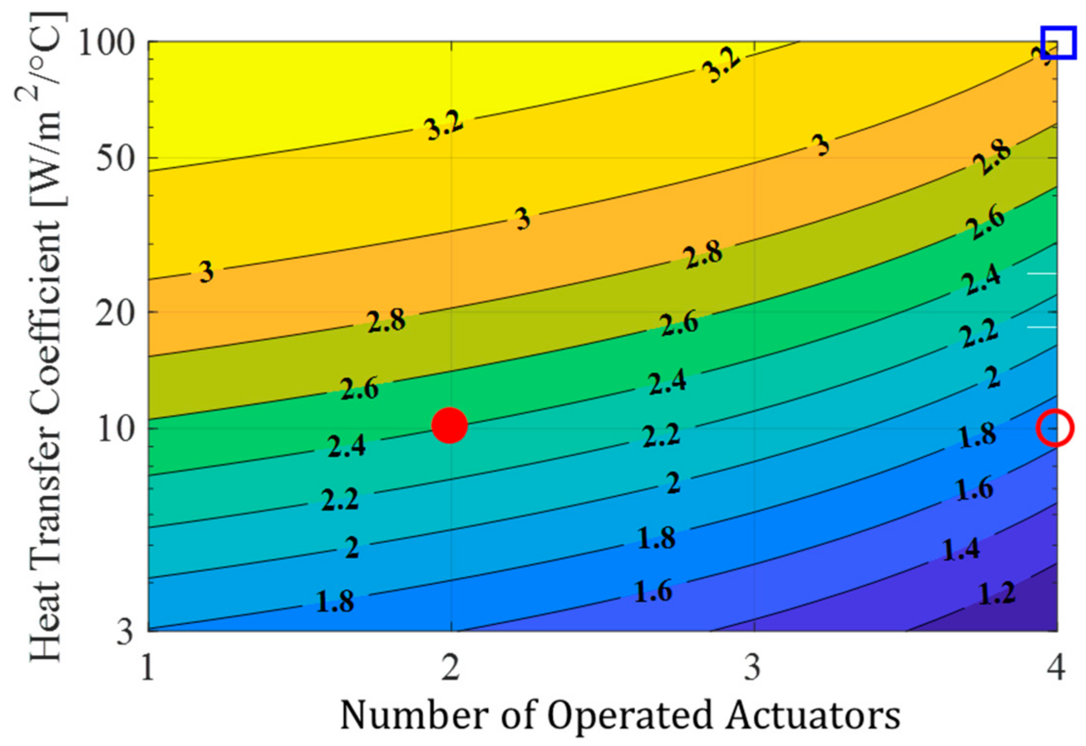
Figure 10 shows a contour plot from the simulation result. The contours represent the changes in the value according to the number of motors used in the 4-CoSMo actuator and the changes in the HTC. When the HTC is 3 , i.e., when all four-unit modules are activated in a natural air-cooling state, shows the minimum value of 1. In contrast, when the HTC is 100 , i.e., when the one-unit module is activated in a forced air-cooling state, is greater than the maximum value of 3. If the system has an HTC of 10 , which is the minimum value of the average HTC of a forced-air-cooling system, is 2.4 or greater when current is applied only to two of the motors of the 4-CoSMo actuator. When all the motors of the 4-CoSMo actuator are activated, is greater than 1.6. If the HTC of the system is 100 , is greater than 3 when the number of the operated motors is one. Therefore, the full loading of all motors rarely occurs in the proposed system, and its effect can be maximized for applications that require lightweight systems.
6. Conclusions
In this paper, we proposed and validated a concentrically stacked modular actuator system with a rotary electric motor. It consists of a serially connected actuator module with an integrated radiator and a single cooling fan. Due to the unique design, the CoSMo actuator system potentially achieves low mechanical impedance by reducing the number of cooling components and placing the actuators concentrically. It is verified by the comparison of the simple dynamic properties between the conventional and the proposed design concept. The most remarkable feature of the CoSMo actuator system is that it has high thermal capacitance and low thermal resistance via the multiple-level stacked structure. Through simulation using the STEC of the CoSMo actuator, it was verified that the current amplification ratio would increase to 1.36, 1.79, and 2.25 when the stack level became 2, 4, and 8, respectively, compared to the unstacked actuator under the natural air-cooling condition. This means that the proposed concept enables the system to carry higher current then the conventional design under the sufficient cooling condition. Also, preliminarily, we found the proper actuator type for the forced cooling system. Based on the motor selection method, a prototype was fabricated. In the experiment, the maximum continuous current was amplified over three-fold compared to the 1-CoSMo actuator in the condition of natural air cooling. This confirmed the validity of the proposed model and its potential application to other areas.
Despite the outstanding features as mentioned above, some discussable issues still remain. First, the presented simulation results are based on theoretical data of the simplified thermal equivalent circuit (STEC), which disregards iron loss. Thus, it has limited accuracy in estimating the current amplification ratio of a high-speed operation area. Second is the discrepancy between the maximum continuous current increase rate and maximum continuous torque increase rate. This is because the torque constant of the motor decreases as the magnetic flux becomes saturated. Thus, an appropriate marginal factor should additionally be applied to the presented results when estimating the torque increase rate.
In the further studies, we will measure the actual torque and power increase rate of the n-CoSMo actuator against dynamic loads. The modular actuator with the proposed structure will be utilized and validated through application in multilimbed robots, such as robotic arms and legged robots, which require a high power-to-mass ratio.
Author Contributions
J.N. conceptualized and designed the concentrically stacked modular actuator. Simulations and experiments were conducted by J.N. with the help of J.L. The majority of the manuscript was written by J.N. and edited by J.L. W.Y. and S.L. oversaw and directed the project.
Funding
This research was supported by the Basic Science Research Program through the National Research Foundation of Korea (NRF) funded by the Ministry of Education (2017R1A2B3010336) and by the Research Grant of Kwangwoon University in 2018.
Conflicts of Interest
The author(s) declared no potential conflicts of interest with respect to the research, authorship, and/or publication of this article.
Abbreviations/Nomenclature
| CoSMo | concentrically stacked modular |
| DOF | degrees of freedom |
| COM | center of mass |
| HTC | heat transfer coefficient |
| STEC | simplified thermal equivalent circuit |
| RMS | root mean square |
References
- Grebenstein, M.; Albu-Schäffer, A.; Bahls, T.; Chalon, M.; Eiberger, O.; Friedl, W.; Gruber, R.; Haddadin, S.; Hagn, U.; Haslinger, R.; et al. The DLR hand arm system. In Proceedings of the IEEE International Conference on Robotics and Automation (ICRA), Shanghai, China, 9–13 May 2011; pp. 3175–3182. [Google Scholar] [CrossRef]
- Kojima, K.; Karasawa, T.; Kozuki, T.; Kuroiwa, E.; Yukizaki, S.; Iwaishi, S.; Nozawa, S. Development of life-sized high-power humanoid robot jaxon for real-world use. In Proceedings of the IEEE-RAS 15th International Conference on Humanoid Robots (Humanoids), Seoul, Korea, 3–5 November 2015; pp. 838–843. [Google Scholar] [CrossRef]
- Asano, Y.; Kozuki, T.; Ookubo, S.; Kawamura, M.; Nakashima, S.; Katayama, T.; Kakiuchi, Y. Human mimetic musculoskeletal humanoid Kengoro toward real world physically interactive actions. In Proceedings of the IEEE-RAS 16th International Conference on Humanoid Robots (Humanoids), Cancun, Mexico, 15–17 November 2016; pp. 876–883. [Google Scholar] [CrossRef]
- Paine, N.; Sentis, L. Design and comparative analysis of a retrofitted liquid cooling system for high-power actuators. Actuators 2015, 4, 182–202. [Google Scholar] [CrossRef]
- Zoss, A.; Kazerooni, H. Design of an electrically actuated lower extremity exoskeleton. Adv. Robot. 2006, 20, 967–988. [Google Scholar] [CrossRef]
- Kollmorgen. Available online: https://kollmorgen.com/en-us/products/motors/direct-drive/tbm-series/ (accessed on 30 September 2018).
- Tecnotion. Available online: https://tecnotion.com/products/torque-motors.html (accessed on 30 September 2018).
- Urata, J.; Nakanishi, Y.; Okada, K.; Inaba, M. Design of high torque and high speed leg module for high power humanoid. In Proceedings of the IEEE/RSJ International Conference Intelligent Robots and Systems, IROS, Taipei, Taiwan, 18–22 October 2010; pp. 4497–4502. [Google Scholar] [CrossRef]
- Kim, D.; Ahn, J.; Campbell, O.; Paine, N.; Sentis, L. Investigations of viscoelastic liquid cooled actuators applied for dynamic motion control of legged systems. In Proceedings of the IEEE-RAS 17th International Conference on Humanoid Robotics, Birmingham, UK, 15–17 November 2018. [Google Scholar] [CrossRef]
- Ito, Y.; Nozawa, S.; Urata, J.; Nakaoka, T.; Kobayashi, K.; Nakanishi, Y.; Inaba, M. Development and verification of life-size humanoid with high-output actuation system. In Proceedings of the IEEE International Conference on Robotics and Automation, Hong Kong, China, 31 May–7 June 2014; pp. 3433–3438. [Google Scholar] [CrossRef]
- Salerno, L.J.; Kittel, P. Thermal Contact Conductance; NASA Technical Memorandum; Ames Research Center, Moffett Filed California: San Francisco, CA, USA, 1997. [Google Scholar]
- Staton, D.; Boglietti, A.; Cavagnino, A. Solving the more difficult aspects of electric motor thermal analysis in small and medium size industrial induction motors. IEEE Trans. Energy Convers. 2005, 20, 620–628. [Google Scholar] [CrossRef]
- Maxon Motor Catalog. Available online: https://www.maxonmotor.com/maxon/view/catalog/ (accessed on 30 September 2018).
- Permanent Magnet DC Motor with Coreless Winding; Technical Report; Maxon Motor: Obwalden, Switzerland, 2012.
- Holman, J.P. Heat Transfer, New York; McGraw-Hill: New York, NY, USA, 1997. [Google Scholar]
- Oosthuizen, P.H.; Naylor, D. Introduction to Convective Heat Transfer Analysis; McGraw-Hill: New York, NY, USA, 1999. [Google Scholar]
Figure 1.
Design of the proposed actuator module; (a) Cross section of the proposed unit module; (b) Isometric view; (c) Cross section of a four-level concentrically stacked modular (4-CoSMo) actuator and the power output joint mechanism; (d) Application example of an eight-level concentrically stacked modular (8-CoSMo) actuator consisting of two 4-CoSMo actuators facing each other (dashed black arrows show the scheme of air flow in the proposed module).
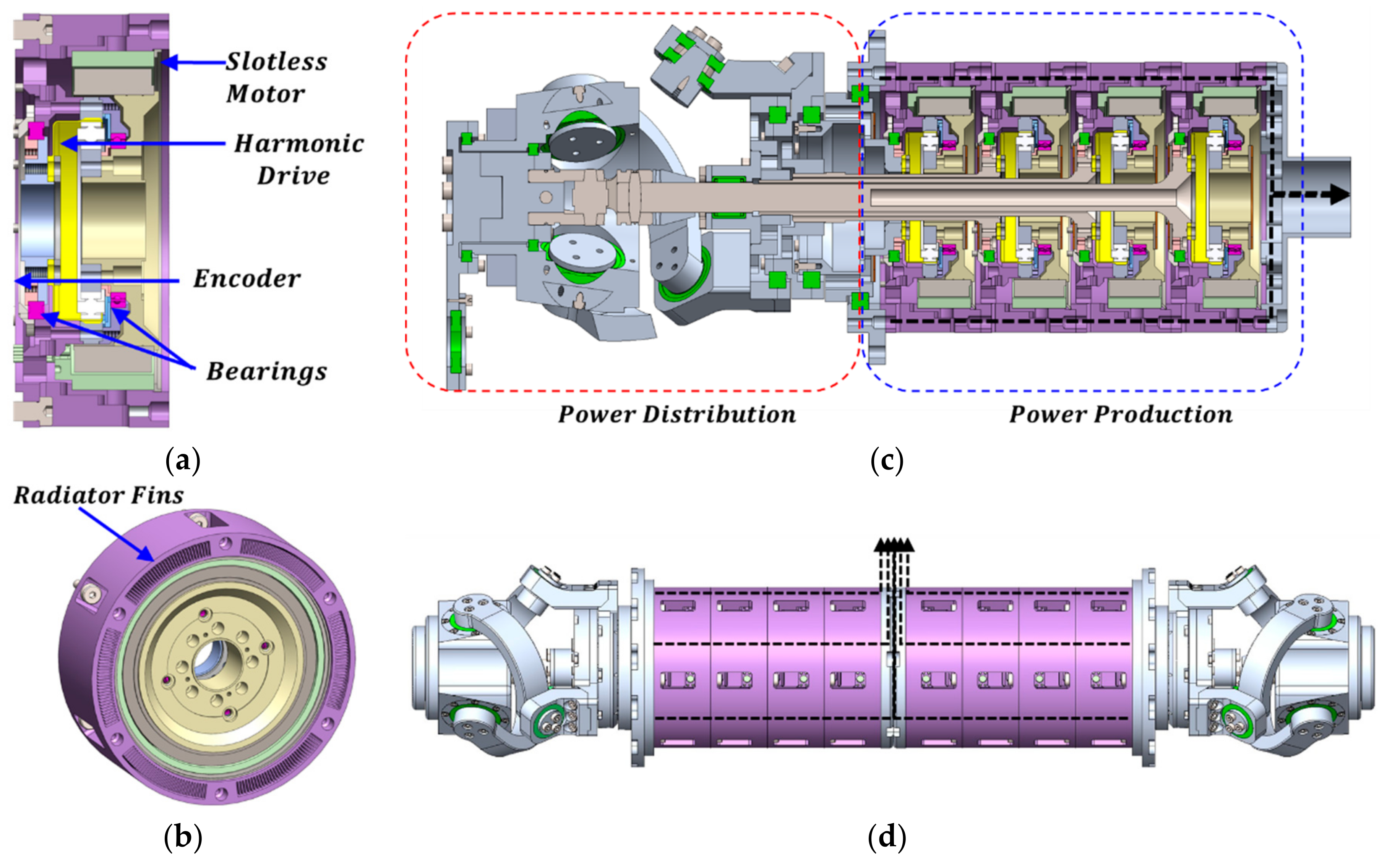
Figure 2.
Design scheme of the traditional forced cooling robotic system.
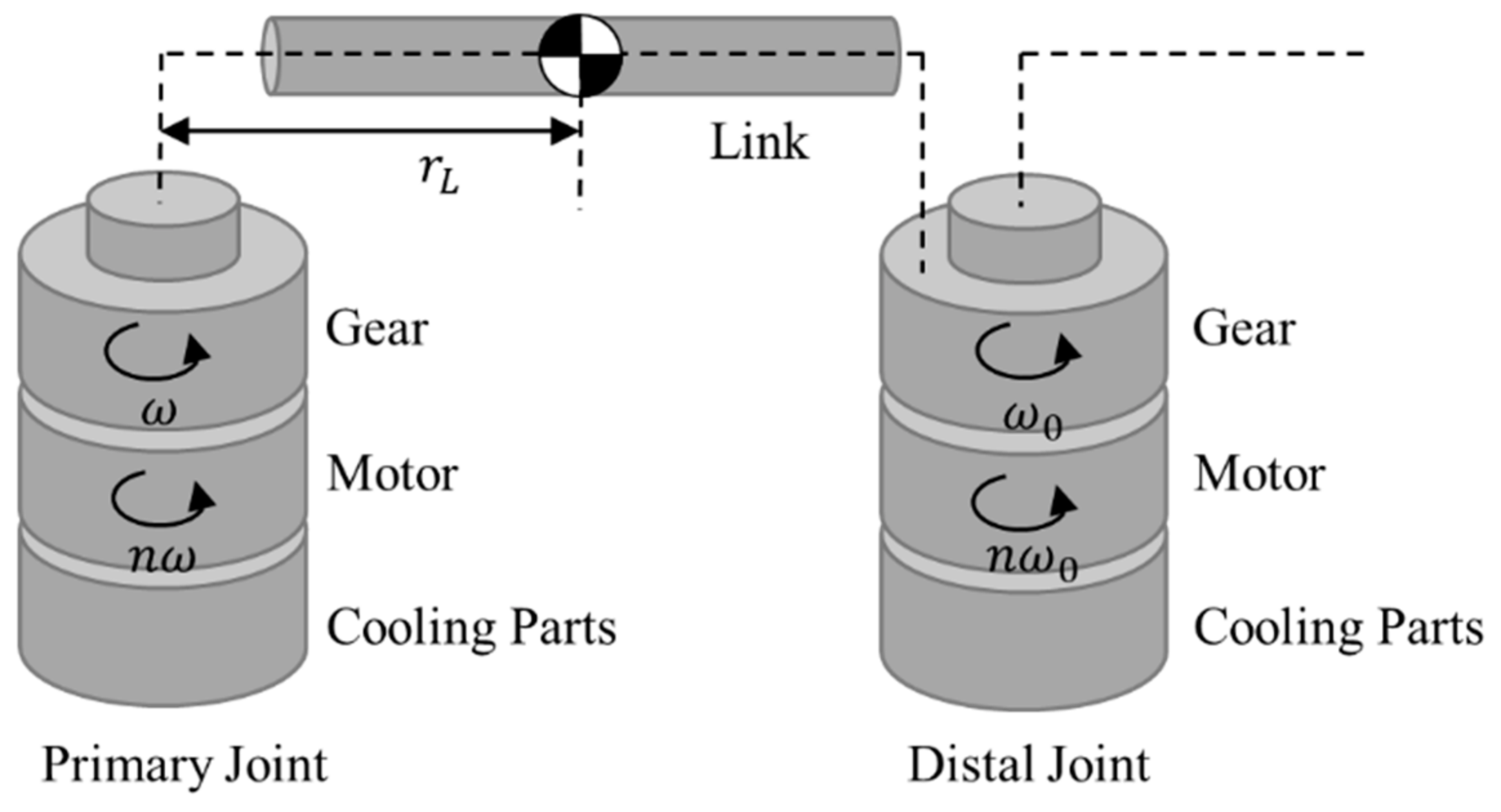
Figure 3.
Load torque of the prior joint for the mass ratio of the actuator module, including the link and cooling part.
Figure 3.
Load torque of the prior joint for the mass ratio of the actuator module, including the link and cooling part.

Figure 4.
Thermal characteristics of motors compared in Table 1 (dashed lines are drawn based on the average values of the slotless motors in each graph); (a,b) Thermal resistance, , against the surface area of the motor and (c,d) thermal capacitance, , against the volume of the motor.
Figure 4.
Thermal characteristics of motors compared in Table 1 (dashed lines are drawn based on the average values of the slotless motors in each graph); (a,b) Thermal resistance, , against the surface area of the motor and (c,d) thermal capacitance, , against the volume of the motor.
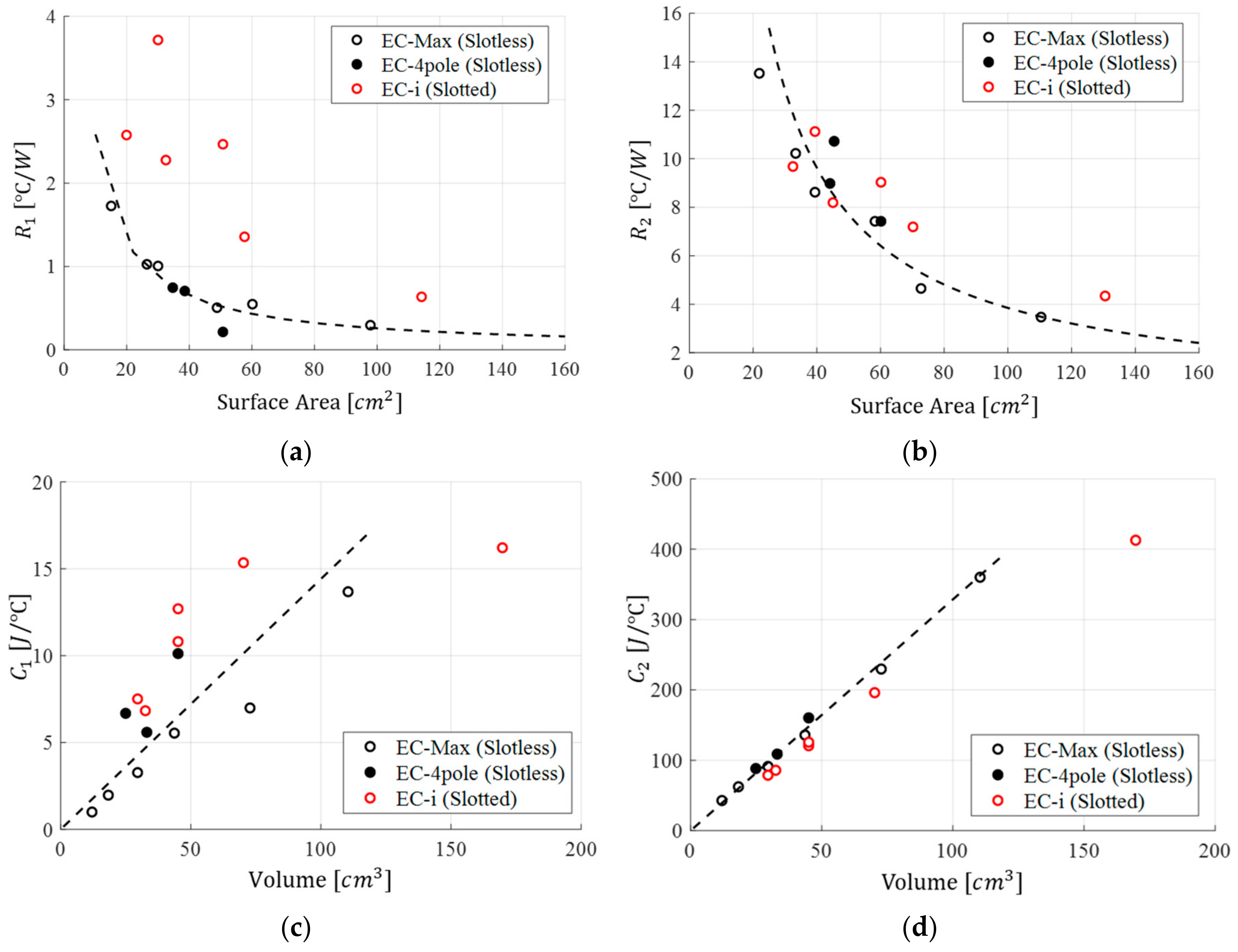
Figure 5.
(a) Simplified thermal equivalent circuit of a normal actuator module; (b) Simplified thermal equivalent circuit of the n-CoSMo actuator.
Figure 5.
(a) Simplified thermal equivalent circuit of a normal actuator module; (b) Simplified thermal equivalent circuit of the n-CoSMo actuator.
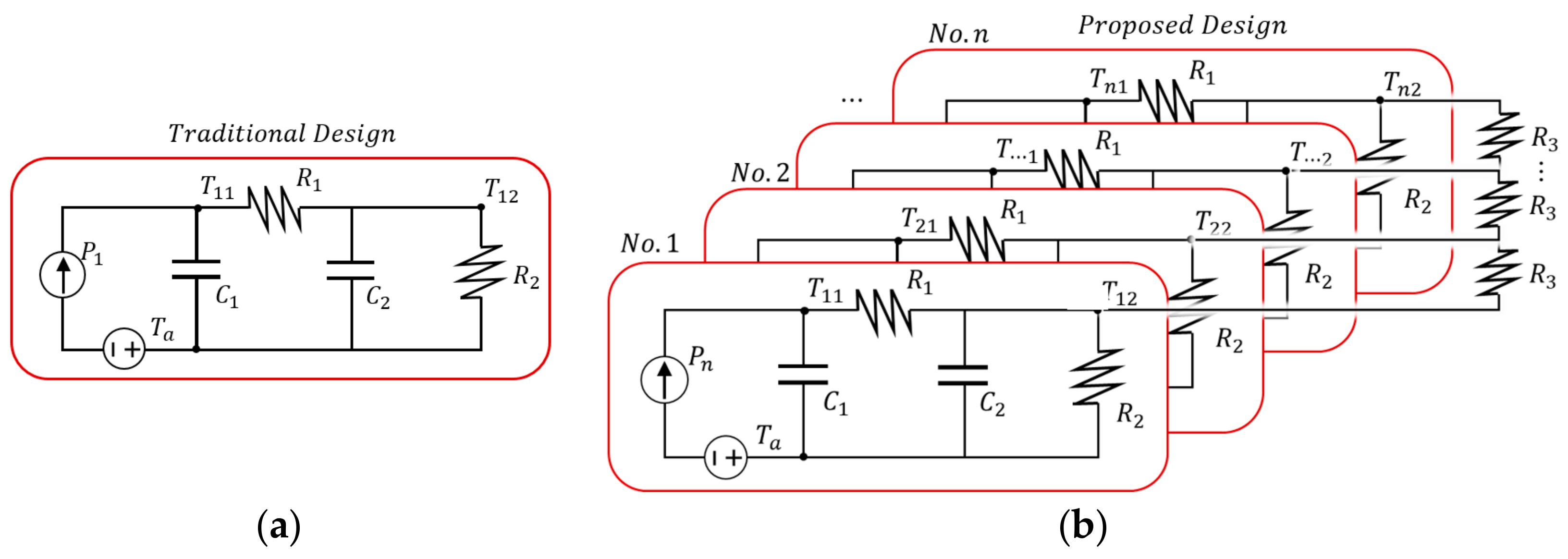
Figure 6.
Simulation results of the current amplification ratio κ against sustainable duration with growing (a) stacking level; (b) heat transfer coefficient in case of unit module; (c) heat transfer coefficient for the 4-CoSMo actuator. (All simulation results illustrate the reactions when thermal load was applied to only one unit module of the stacked modular actuator.)
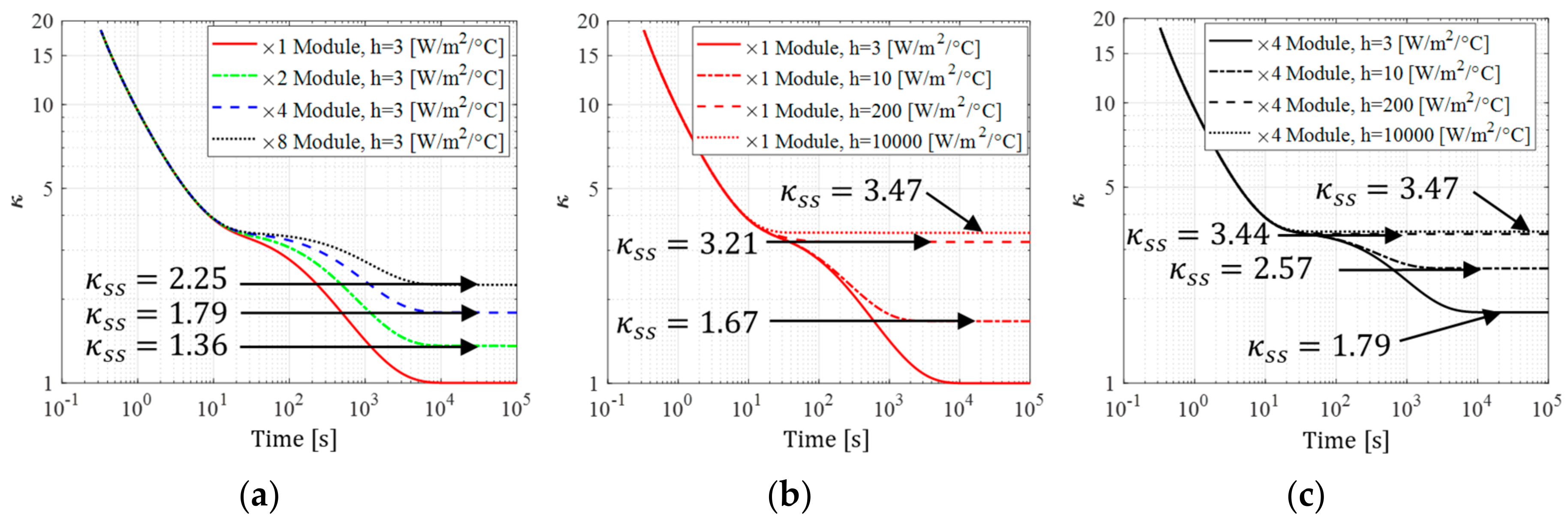
Figure 7.
Prototype of the proposed design module; (a) Experimental setup of the thermoelectric camera and prototype module (the red circle shows the hole for measuring stator surface temperature, the blue square shows the prototyped CoSMo actuator set, and the black square shows the blower for the forced circulation of air); (b) Prototype module including joint part; (c) Stator of the frameless slotless motor; (d) Housing part with built-in radiator.
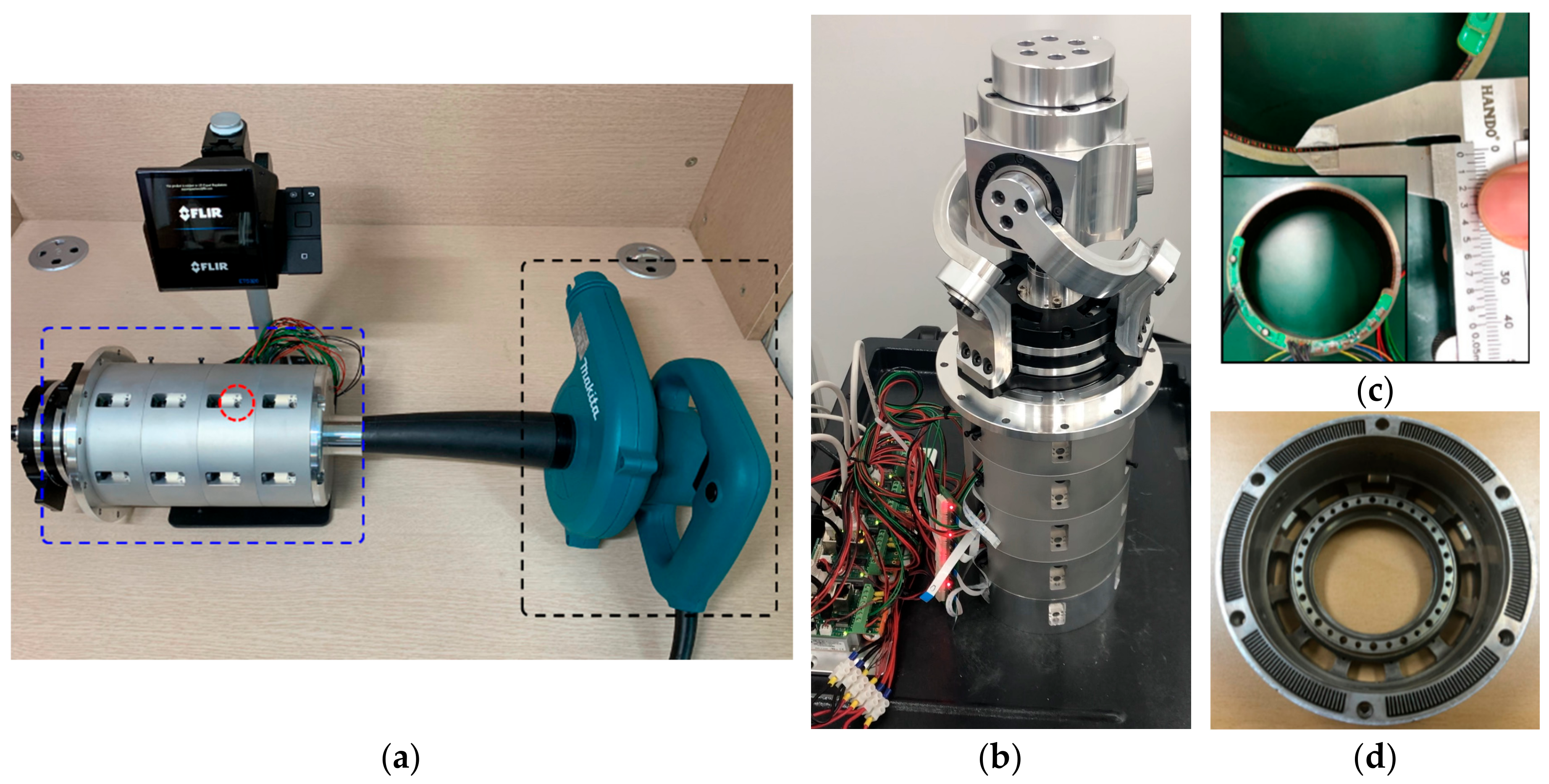
Figure 8.
(a) Thermal responses of the motor without housing; (b) Thermal responses of the motor with housing in the forced air-cooling condition.
Figure 8.
(a) Thermal responses of the motor without housing; (b) Thermal responses of the motor with housing in the forced air-cooling condition.
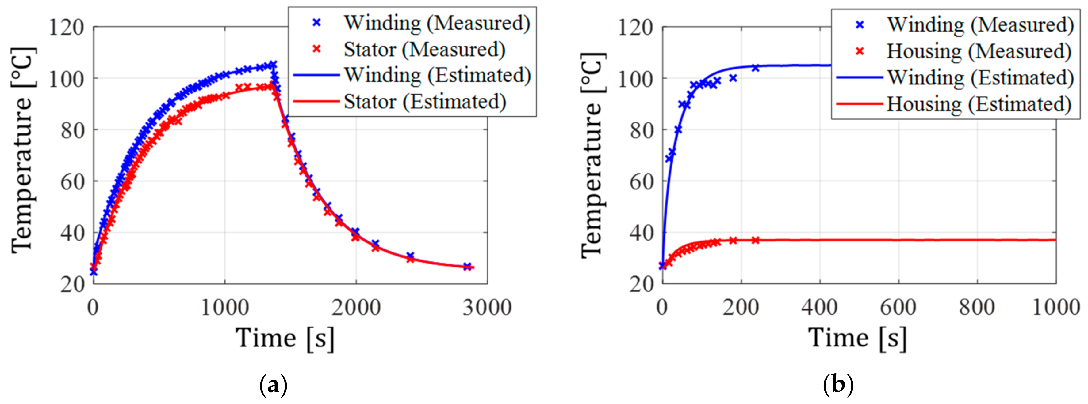
Figure 9.
Thermal response of the 4-CoSMo actuator in the forced air-cooling condition.
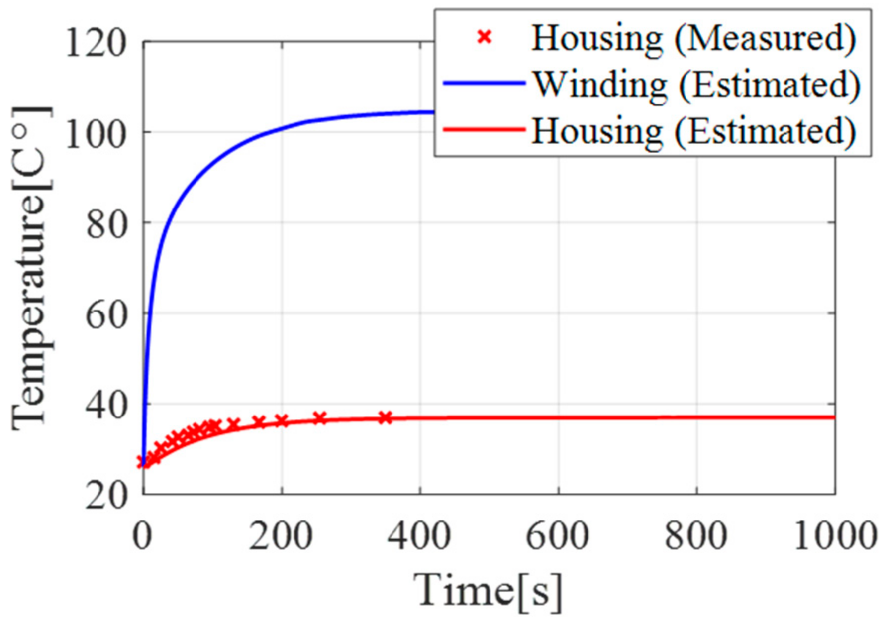
Figure 10.
Contour plot of against the number of operated actuators of the 4-CoSMo, and heat transfer coefficient from the simulation. Here, the red-filled circle, red-empty circle and blue square mean that is about 2.4, 1.6 and 3, respectively.
Figure 10.
Contour plot of against the number of operated actuators of the 4-CoSMo, and heat transfer coefficient from the simulation. Here, the red-filled circle, red-empty circle and blue square mean that is about 2.4, 1.6 and 3, respectively.

Table 1.
Major parameters for thermal performance of compared motors.
| Type | Diameter | Length | R1 | R2 | C1 | C2 | |
|---|---|---|---|---|---|---|---|
| Slotless Type | EC-Max | 40 | 88 | 0.29 | 3.45 | 13.7 | 359.4 |
| EC-Max | 30 | 62 | 0.5 | 7.4 | 5.5 | 135.1 | |
| EC-4pole | 30 | 64 | 0.209 | 7.4 | 10.1 | 159.5 | |
| EC-4pole | 30 | 47 | 0.74 | 8.96 | 5.6 | 108.0 | |
| EC-4pole | 22 | 66 | 0.7 | 10.7 | 6.7 | 87.5 | |
| Slotted Type | EC-i | 52 | 80 | 0.63 | 4.32 | 16.2 | 412.0 |
| EC-i | 40 | 36 | 2.27 | 8.17 | 10.8 | 124.8 | |
| EC-i | 30 | 36 | 2.46 | 9.01 | 13.3 | 121.0 | |
| EC-i | 30 | 42 | 3.71 | 11.1 | 7.5 | 78.0 | |
| EC-i | 40 | 56 | 1.35 | 7.17 | 15.3 | 195.3 | |
| Unit | mm | mm | |||||
Table 2.
Parameters of the state–space model.
| Parameter | Values |
|---|---|
Table 3.
Specifications of the actuator in the prototype.
| Specification | Value | Unit |
|---|---|---|
| Max. Continuous Torque | 1.76 | Nm |
| Max. Speed | 4600 | rpm |
| Max. Continuous Power | 850 | W |
| Diameter | 105 | mm |
| Stator Length | 25 | mm |
| Mass | 0.65 | kg |
© 2018 by the authors. Licensee MDPI, Basel, Switzerland. This article is an open access article distributed under the terms and conditions of the Creative Commons Attribution (CC BY) license (http://creativecommons.org/licenses/by/4.0/).
Share and Cite
MDPI and ACS Style
Noh, J.; Lee, J.; Yang, W.; Lee, S. Design of a Concentrically Stacked Modular Actuator with Forced Air Cooling for Multi-DOF Robotic Systems. Energies 2018, 11, 2947. https://doi.org/10.3390/en11112947
AMA Style
Noh J, Lee J, Yang W, Lee S. Design of a Concentrically Stacked Modular Actuator with Forced Air Cooling for Multi-DOF Robotic Systems. Energies. 2018; 11(11):2947. https://doi.org/10.3390/en11112947
Chicago/Turabian StyleNoh, Jaeho, Jaeyong Lee, Woosung Yang, and Sungon Lee. 2018. "Design of a Concentrically Stacked Modular Actuator with Forced Air Cooling for Multi-DOF Robotic Systems" Energies 11, no. 11: 2947. https://doi.org/10.3390/en11112947
Note that from the first issue of 2016, this journal uses article numbers instead of page numbers. See further details here.