Article

Efficiency Reduction in Stirling Engines Resulting from Sinusoidal Motion

by
Salvatore Ranieri
1,
Gilberto A. O. Prado
1,2 and
Brendan D. MacDonald
1,*
1
Faculty of Engineering and Applied Science, University of Ontario Institute of Technology, 2000 Simcoe Street North, Oshawa, ON L1H 7K4, Canada
2
Mechanical Engineering Department, Federal Technological Education Centre, CEFET-MG, Av. Amazonas, 7675, Nova Gameleira, Belo Horizonte 30410-000, MG, Brazil
*
Author to whom correspondence should be addressed.
Energies 2018, 11(11), 2887; https://doi.org/10.3390/en11112887
Submission received: 11 September 2018 / Revised: 11 October 2018 / Accepted: 22 October 2018 / Published: 24 October 2018
(This article belongs to the Section I: Energy Fundamentals and Conversion)

Abstract

:
Stirling engines have a high potential to produce renewable energy due to their ability to use a wide range of sustainable heat sources, such as concentrated solar thermal power and biomass, and also due to their high theoretical efficiencies. They have not yet achieved widespread use and commercial Stirling engines have had reduced efficiencies compared to their ideal values. In this work we show that a substantial amount of the reduction in efficiency is due to the operation of Stirling engines using sinusoidal motion and quantify this reduction. A discrete model was developed to perform an isothermal analysis of a 100cc alpha-type Stirling engine with a 90 phase angle offset, to demonstrate the impact of sinusoidal motion on the net work and thermal efficiency in comparison to the ideal cycle. For the specific engine analyzed, the maximum thermal efficiency of the sinusoidal cycle was found to have a limit of 34.4%, which is a reduction of 27.1% from Carnot efficiency. The net work of the sinusoidal cycle was found to be 65.9% of the net work from the ideal cycle. The model was adapted to analyze beta and gamma-type Stirling configurations, and the analysis revealed similar reductions due to sinusoidal motion.

1. Introduction

Stirling engines have high theoretical efficiencies and can be powered by external heat sources; therefore, there is a high degree of potential for Stirling engines to produce renewable energy from several sustainable sources, such as concentrated solar thermal power and biomass. Theoretically, Stirling engines can convert heat into mechanical energy at the Carnot efficiency [1,2], which is the maximum achievable efficiency for heat engines, but in practice Stirling engines have failed to achieve these high efficiencies and the reduction is more than would be predicted by typical mechanical losses alone [3]. The practical efficiency depends on many factors, including the operating conditions, regenerator effectiveness [4], friction losses [5,6], dead volume [7], and the ability of the engine to follow the theoretical Stirling cycle. In this study we focus on the ability of an engine to follow the theoretical Stirling cycle, because the previous factors result in losses that do not account for the substantial efficiency reductions experienced in commercial Stirling engines. Ideally, the Stirling cycle is composed of two isothermal processes and two isochoric regeneration processes. To attain the Carnot efficiency, it is critical for the practical engine configurations to reproduce these processes precisely. Typical commercial Stirling engine configurations use pistons connected to a crankshaft or a free piston arrangement, both of which result in continuous sinusoidal movement with a phase angle difference between the pistons [8,9,10]. This arrangement deviates from the theoretical Stirling cycle since the pistons do not adequately dwell and isolate the working fluid in either the hot or cold cylinder(s) during the expansion and compression processes respectively. This study answers the question of what impact this deviation has on the efficiency of Stirling engines and quantifies the effect.
Several studies have been performed to analyze the work output from a Stirling engine with sinusoidal movement and a phase angle difference between the pistons. An early study by Schmidt [11] provided sinusoidal volume variation of the working volume in reciprocating engines, with the major assumptions of isothermal compression and expansion, and of perfect regeneration [12]. Finkelstein [13] expanded on Schmidt’s work by optimizing power parameters for varying phase angles and volume ratios, and adding entropy and heat transfer analyses. Walker [14] and Kirkley [15] also expanded on Schmidt’s work to test different input variables, such as temperature ratio, phase angle, swept volume ratio, and dead volume, in order to maximize a set of dimensionless power parameters. Urieli and Berchowitz [16] expanded on Schmidt’s calculation by adding the concept of heat rejector and acceptor spaces, into an isothermal analysis. Senft [17] employed the analysis from Walker [14] and Kirkley [15] for gamma-type engines. More recently, Cheng and Yu [18] developed a numerical model to analyze a beta-type Stirling cycle, outlining the functional dependencies of the heat source temperature, displacer gap and rhombic drive gear offset as a function of work output. Cinar [19] investigated the effects of varying phase angle in an alpha Stirling engine with an adiabatic heat transfer limited model. Tlili et al. [20] determined the optimal operating parameters for a mean temperature differential Stirling engine. Formosa and Despesse [21] added flow considerations to the isothermal model. Cheng and Yang [22] developed a theoretical numerical model to optimize Stirling engine features, including swept volume ratio between the hot and cold sides of the engine, phase angle, dead volume ratio, and temperature ratio. Alfarawi et al. [23] presented the development and validation of a CFD model on a gamma-type Stirling engine to demonstrate the effects of a variety of phase angles on power output. Briggs [9] showed that power density could be increased by modifying the sine wave for prolonged dwell in a free-piston Stirling arrangement, and found that efficiency was reduced. These works have all developed their analyses considering sinusoidal motion of the pistons, which deviates from the ideal Stirling cycle; however, there have been no studies that calculate and analyze the deviation in efficiency between the ideal Stirling cycle and the cycle resulting from sinusoidal motion.
In this paper, we developed a discrete model to understand and quantify the impact of sinusoidal motion on the efficiency of a Stirling engine. The isothermal assumption was used in the model and the working fluid was air, which was treated as an ideal gas. The phase angle was also varied to determine the influence of phase angle on the efficiency of Stirling engines. The corresponding P-v and T-s diagrams were generated to illustrate the deviation in efficiency resulting from the sinusoidal motion. The results from sinusoidal motion were compared to the ideal Stirling cycle to show the efficiency reduction resulting solely from the use of sinusoidal motion in Stirling engines.

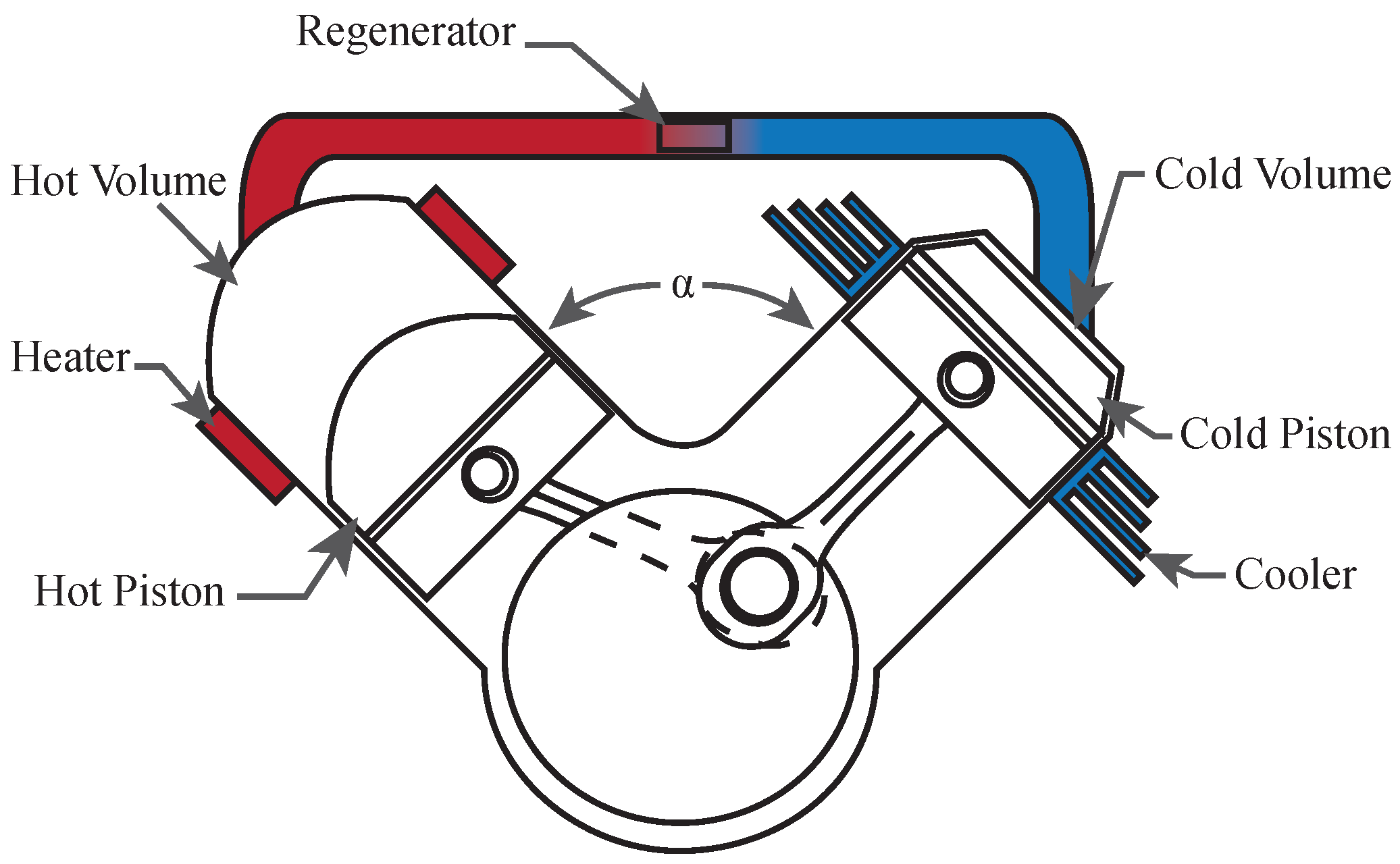
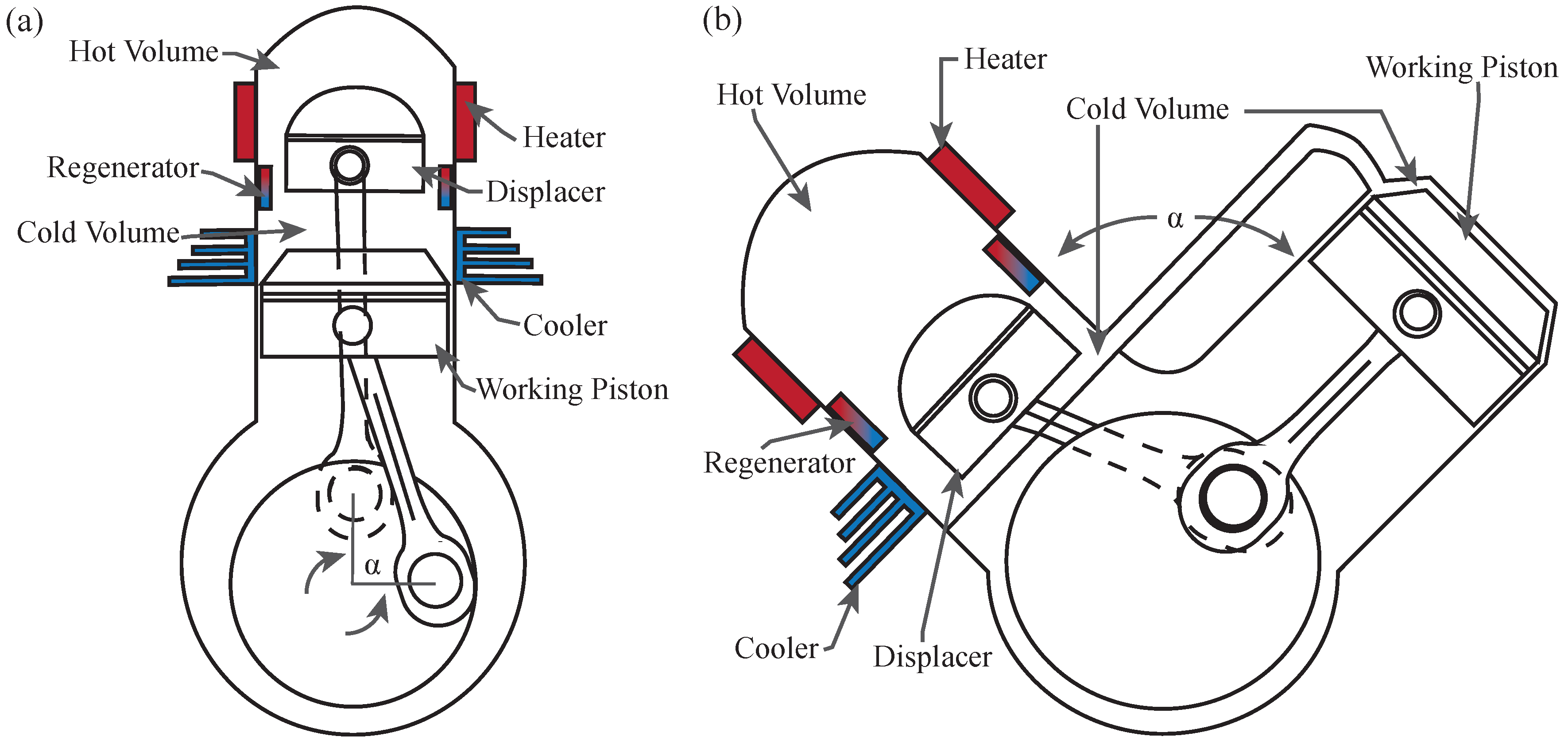
2. Engine Description

We model an alpha-Stirling engine configuration, which is comprised of individual compression and expansion piston-cylinder devices that share a common cranking mechanism, offset by a phase angle, α , as shown in Figure 1. This arrangement results in continuous sinusoidal operation. We apply the isothermal assumption, which considers the working fluid to have a uniform temperature throughout each of the cylinders, corresponding to the temperature of the heat source and sink for the hot and cold cylinders respectively. The system is a closed cycle, with a regenerator located in the passageway connecting the cylinders, as seen in Figure 1.
Comparisons of the example engine are made against an ideal Stirling engine equivalent. The ideal engine is constrained to the same volume and temperature limits as the example engine. The ideal engine differs from the example engine by operating with isothermal expansion and compression work processes, and isochoric regeneration processes.
The Stirling engine in our analysis was sized to provide power for a generic residential or small pump application and used as a reference to quantify results according to the values listed in Table 1. The total dead volume refers to the unswept volume. Total mass of the working fluid was determined using the ideal gas law at ambient conditions at the maximum engine volume at atmospheric pressure while the phase angle, α , was set to 90 . The analysis was also performed for various temperature ratios to demonstrate that the conclusions from this study apply generally and not specifically.

3. Thermodynamic Model

3.1. Discretization Approach

To quantify the impact of sinusoidal motion constrained by a crank shaft, the divergence from the ideal cycle must be analyzed. The approach was to divide a full oscillation into discrete crankshaft intervals, and analyze the volumetric changes and associated thermodynamic intensive and extensive properties of the system. The calculations were performed using incremental steps of 5 for crank angle θ . This step size was validated by Martini [3] in a numerical analysis, to generate less than 0.5% error when compared to an isothermal analytical solver.

3.2. Calculating the System Variables

The total system volume, V t o t a l , is divided among the hot, regenerator, and cold volume, denoted as V H , V R and V C respectively. They are expressed as a function of the crank angle position, θ , where 0 refers to the hot piston at top dead center, according to:
V t o t a l ( θ ) = V H ( θ ) + V R + V C ( θ ) .
The pistons follow sinusoidal motion, so the volume of each compartment varies with crank angle position according to:
V H ( θ ) = V H , m a x 2 ( 1 cos θ ) + V D H ,
V C ( θ ) = V C , m a x 2 ( 1 cos ( θ α ) ) + V D C ,
where α is the phase angle difference between the pistons, and V D H and V D C are the dead volumes associated with the hot and cold volume respectively.
The total mass of the system, m s y s t e m , is divided among the mass of the working fluid located in the hot volume, regenerator, and cold volume, denoted as m H , m R and m C respectively:
m s y s t e m = m H ( θ ) + m R ( θ ) + m C ( θ ) .
Specific volume, v, can be computed as a function of the crank angle:
v ( θ ) = V ( θ ) m s y s t e m .
By substituting ideal gas expressions for the mass associated with the individual engine compartments into Equation (4), we can solve for the engine pressure as a function of crank angle:
P ( θ ) = m s y s t e m R V H ( θ ) T H + V R T R + V C ( θ ) T C .
Pressure is considered to be uniform throughout all of the engine compartments at each point in the cycle. The constant, R, is the ideal gas constant.
The effective fluid regenerator temperature, T R , is calculated as the log mean temperature as follows [3]:
T R = T H T C ln T H T C .
The entropy change of the system is calculated using the variable specific heat reference entropy, and can be written in terms of crank angle, θ , as follows [1]:
s ( θ ) = s ( T g l o b a l ( θ Δ θ ) ) + s ( T g l o b a l ( θ ) ) s ( T g l o b a l ( θ Δ θ ) ) R ln ( P ( θ ) P ( θ Δ θ ) ) ,
where entropy associated with θ is the current crankshaft position and Δ θ is the 5 crankshaft increment.
The global temperature is defined as the mean temperature across the whole system as follows:
T g l o b a l ( θ ) = P ( θ ) V t o t a l ( θ ) m s y s t e m R .

3.3. Calculating the Energy Transfer

As mentioned in the introduction section, the ideal Stirling cycle requires isolation of the working fluid in the hot and cold cylinders during expansion and compression respectively. In engines that have sinusoidal operation, the working fluid is located in both the hot and cold cylinders during the expansion and compression strokes. In order to capture the thermodynamic behavior resulting from a sinusoidal engine, we track the work done on and by the system for each of the pistons throughout the entire cycle.
We calculate the incremental work done at each step of the discrete crank angle values for the hot and cold cylinders as follows:
W H ( θ ) = P V H ( θ + Δ θ ) V H ( θ ) ,
W C ( θ ) = P V C ( θ + Δ θ ) V C ( θ ) .
The heat input is then calculated corresponding to the work values such that at each step where the work is a positive value in either cylinder, there is considered to be a heat input to the system:
Q i n = W H ( θ ) > 0 + W C ( θ ) > 0 .
Similarly, for the heat output:
Q o u t = W H ( θ ) < 0 + W C ( θ ) < 0 .
The net work output resulting from a complete cycle can be calculated as follows:
W n e t = Q i n Q o u t .

3.4. Mass Calculation

The sinusoidal operation of the engine results in the working fluid located in both the hot and cold cylinders during the compression and expansion strokes, as described previously, but there is also potential for non-ideal mass transfer back and forth the between the cylinders during engine operation. To capture this behavior in our model, we calculate the mass occupying the compression, expansion, and regenerator volume at each of the discrete crank angle values as follows:
m C ( θ ) = P ( θ ) V C ( θ ) R T C ,
m H ( θ ) = P ( θ ) V H ( θ ) R T H ,
m R ( θ ) = P ( θ ) V R R T R .

3.5. Efficiency Calculation

We calculate the thermal efficiency of the Stirling engine as follows [1]:
η t h = W n e t Q i n .

4. Results and Discussion

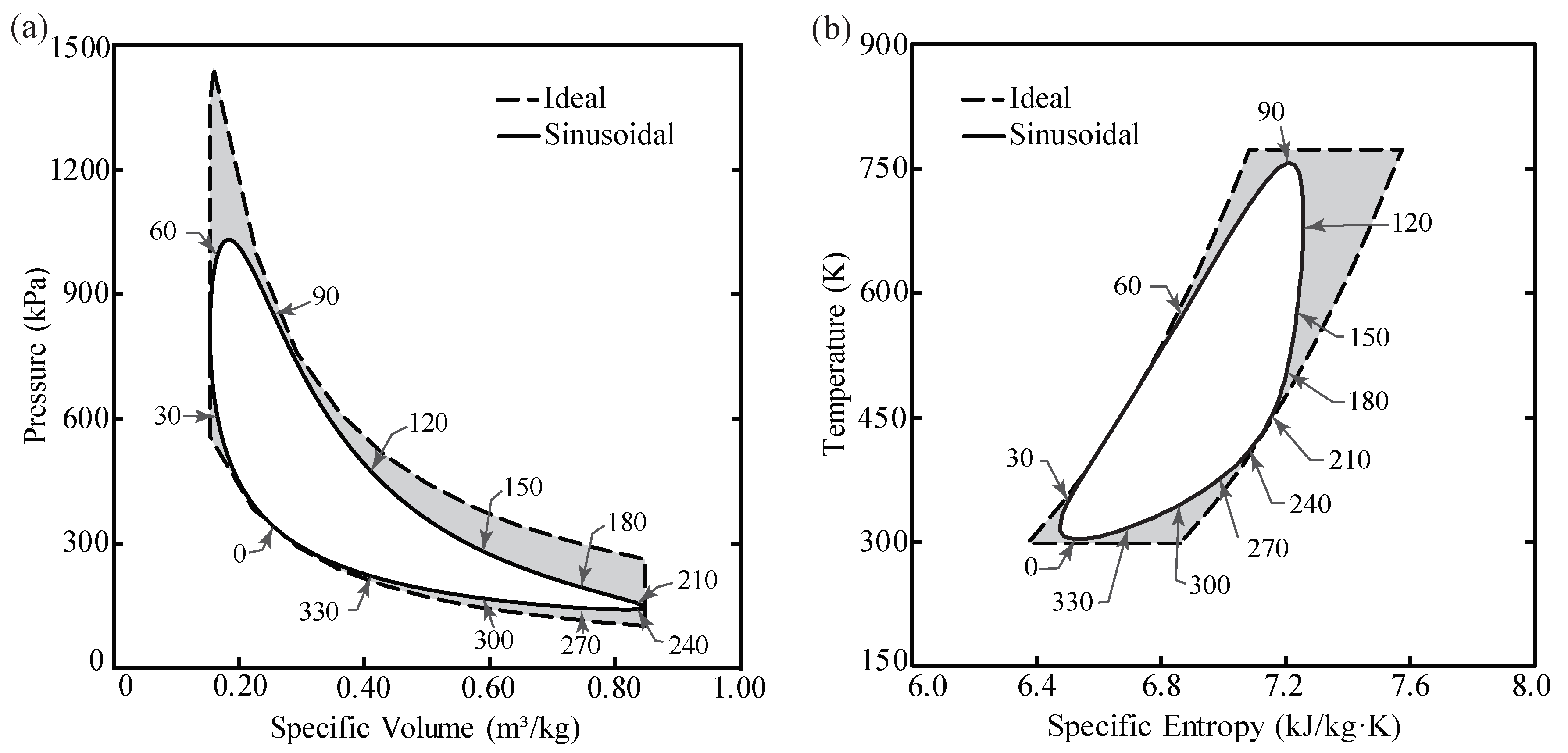
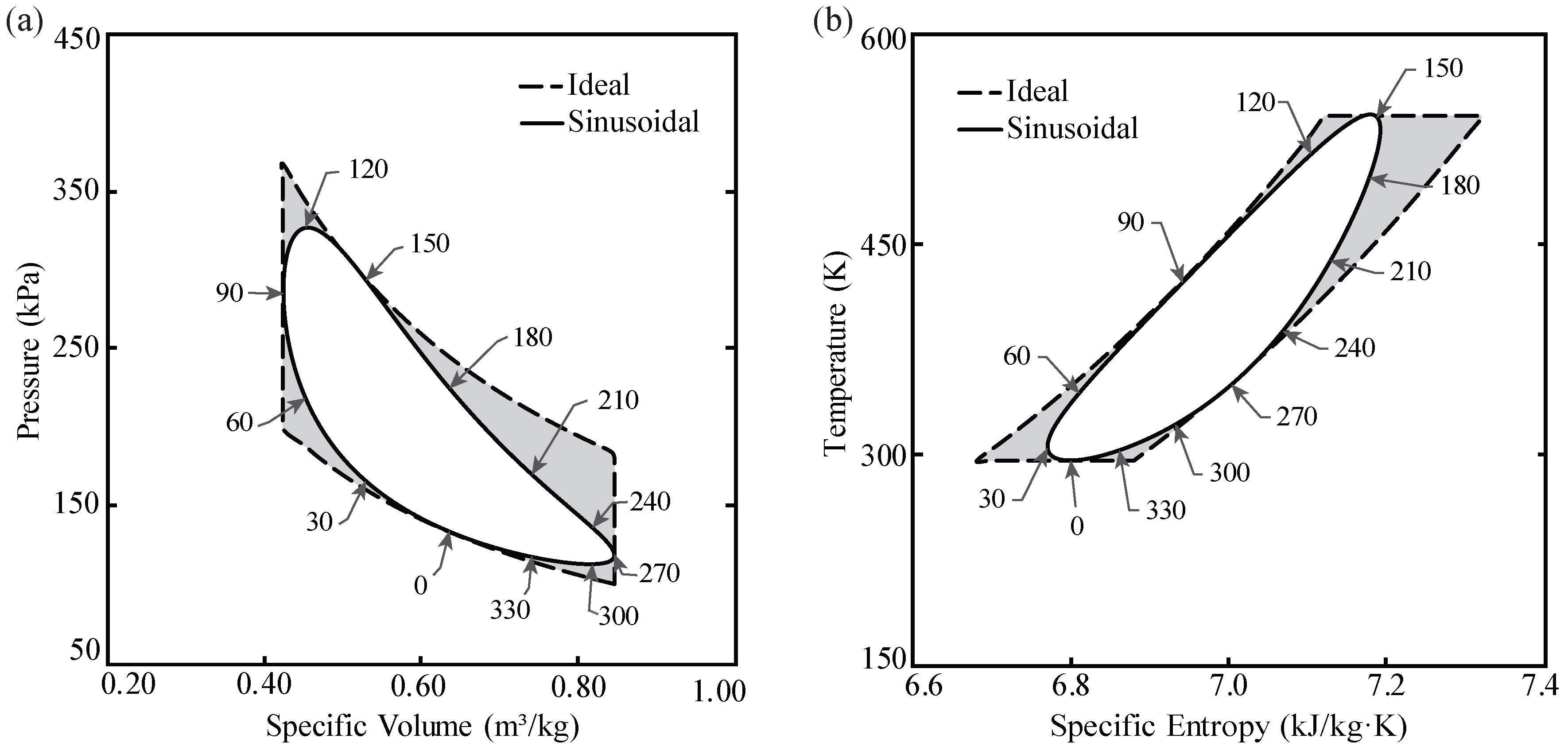
4.1. P-v and T-s Diagrams
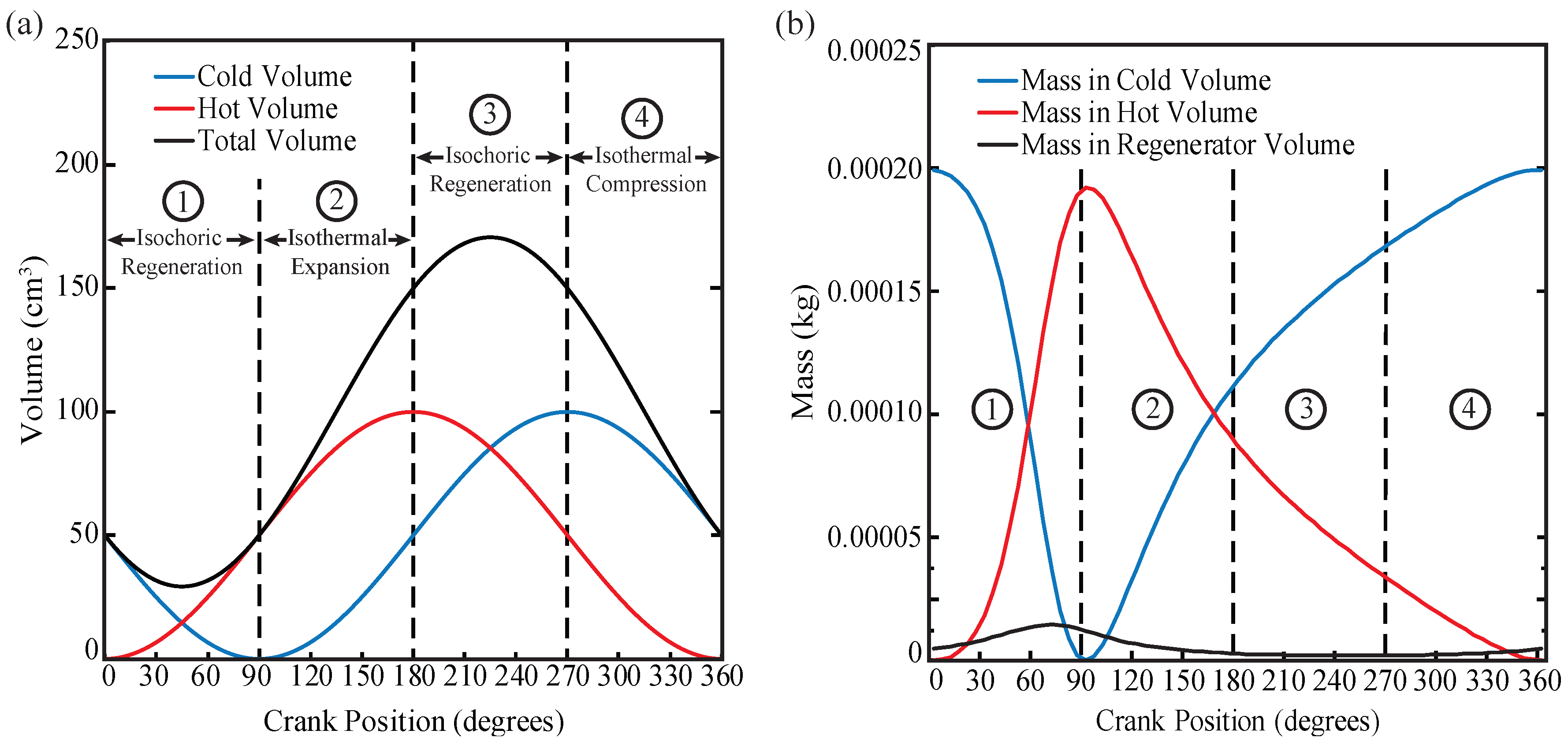
Engine cycles can be visualized on P-v and T-s diagrams to illustrate their performance characteristics [1]. The cycle resulting from sinusoidal motion is plotted on P-v and T-s diagrams in Figure 2, using Equations (5), (6), (8) and (9). The ideal Stirling cycle is plotted using the same equations but fixing the variables to achieve the four ideal processes: isochoric heat addition (regeneration), isothermal expansion, isochoric heat rejection (regeneration), and isothermal compression. The region shaded in gray in Figure 2 shows the deviation of the sinusoidal cycle from the ideal cycle, and corresponds to the work that could have been produced if the cycle was not limited by the sinusoidal motion. Figure 2 shows that much of the reduction from the potential work output is between the crank angles of 60 and 210 and we describe the specific reasons for this reduction by examining each process individually in the following sections.

4.1.1. Isochoric Regeneration ( 0 90 )

Crank angles from 0 to 90 correspond to the constant volume (isochoric) regeneration process, where in the ideal cycle, both pistons would move simultaneously, transferring the mass of the working fluid from the cold side of the engine to the hot side of the engine. In doing so, the working fluid would obtain the heat from the regenerator while producing zero net boundary work, and ideally results in a vertical line on the P-v diagram, as shown in Figure 2a. However, with sinusoidal operation, the curve is rounded and only achieves constant volume for a small portion of the stroke, at 45 . For the sinusoidal cycle, the total volume of the system is plotted in Figure 3a alongside the individual volumes of the hot and cold pistons. The amount of mass of the working fluid located in each volume, and in the regenerator, is plotted in Figure 3b. Figure 3a shows that the total volume is reducing from 0 to 45 and is increasing from 45 to 90 , due to the variation in the speed of the pistons, with constant volume only at 45 , corroborating the result seen in Figure 2. The increase in volume from 45 to 90 results in a decrease in the maximum pressure that can be attained, and as seen in Figure 2a, the maximum pressure of the sinusoidal cycle is reduced from potentially 1445 kPa to 1032 kPa. This thermodynamic discrepancy reduces the potential net work of the system and can be witnessed by the gray shading in the upper left corner of both the P-v and T-s diagrams in Figure 2.

4.1.2. Isothermal Expansion ( 90 180 )

Crank angles from 90 to 180 correspond to the work production process by isothermal expansion. In the ideal cycle, the working fluid would be isolated in the expanding hot volume while the hot piston travels along its stroke. However, in the sinusoidal cycle, this is only true for a small portion of the stroke, at 90 , where the working fluid is located almost entirely in the hot volume, as seen in Figure 3b. Due to the continuous sinusoidal movement of both the hot and cold pistons, the working fluid is located partially in the cold volume during expansion, and just prior to 180 more than half of the mass is located in the cold volume, as shown in Figure 3b. Expanding a mixture of both hot and cold fluid produces substantially less work than expanding only the hot fluid. This thermodynamic discrepancy results in the largest deviation between sinusoidal and ideal operation, and can be seen by the gray shaded region in the upper right corner of both the P-v and T-s diagrams in Figure 2.

4.1.3. Isochoric Regeneration ( 180 270 )

Crank angles from 180 to 270 correspond to the constant volume (isochoric) regeneration process, where the hot working fluid is transferred across the regenerator and the heat is stored. In the ideal cycle this involves both pistons moving simultaneously while transferring the working fluid from the hot volume to the cold volume. In the sinusoidal cycle, the constant volume operation is achieved momentarily at 225 , with the volume increasing from 180 to 225 and decreasing from 225 to 270 , as seen in Figure 3a. The volume variation prevents the sinusoidal cycle from following a straight downward line on the P-v diagram, as seen in Figure 2a, and thus not following the ideal Stirling cycle.

4.1.4. Isothermal Compression ( 270 360 )

Crank angles from 270 to 360 correspond to the work input by isothermal compression. In the ideal cycle, the working fluid would be isolated in the cold volume and the cold piston would travel from its maximum to its minimum volume in accordance with the compression ratio. With sinusoidal operation, the compression stroke begins with some of the working fluid located in the hot volume, as seen in Figure 3b, which increases the work input required for the cold piston to complete the compression stroke due to the higher average specific volume of the working fluid. This deviation can be seen from the gray shaded area in Figure 2 in the bottom right corner of both the P-v and T-s diagrams.

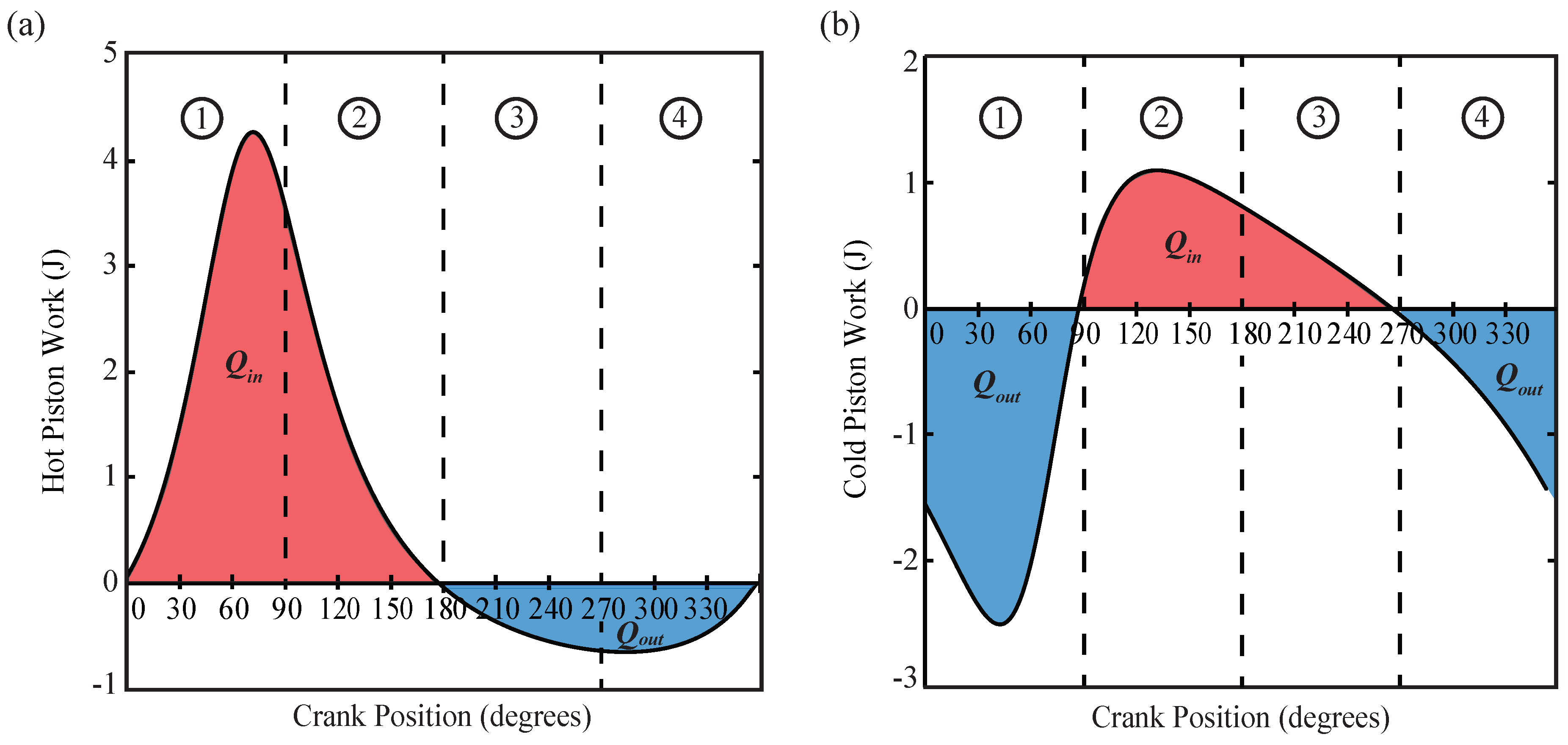
4.2. Work and Heat Transfer

Our analysis of the work thus far has been primarily qualitative, and in this section, we examine the work and heat transfer quantitatively. The work is plotted in Figure 4 versus the crank angle, and summarized in Table 2, for the hot and cold pistons separately.
In the ideal Stirling cycle, work output occurs only in the hot volume, and work input occurs only in the cold volume. This can be accomplished by having the cold piston remain at rest during the expansion stroke, and the hot piston remain at rest during the compression stroke. During the isochoric regeneration processes, the ideal cycle would result in equal but opposite work profiles between the hot and cold pistons, cancelling the net effect. The sinusoidal cycle does not maintain constant volume during regeneration, as described above, and the pistons do not remain at rest during the expansion and compression strokes. To quantify the work that results from these deviations, Equations (10) and (11) are plotted in Figure 4.
The work is plotted in Figure 4 and the corresponding heat transfer is labelled as Q i n and Q o u t , with Q i n shown as red and Q o u t shown as blue. By analyzing the piston work shown in Figure 4 and Table 2, we can quantify the individual work and heat transfer from each piston during each process. Table 2 shows that the hot piston is responsible for the majority of the work output and corresponding heat addition, while the cold piston has more work input and corresponding heat rejection. However, due to the sinusoidal motion, the alpha-Stirling engine is only able to produce 31.6 J of work per revolution, which is only 65.9% of its theoretical limit, and thus the gray shaded region in Figure 2 corresponds to a 34.1% reduction in potential work output, for the values listed in Table 1.

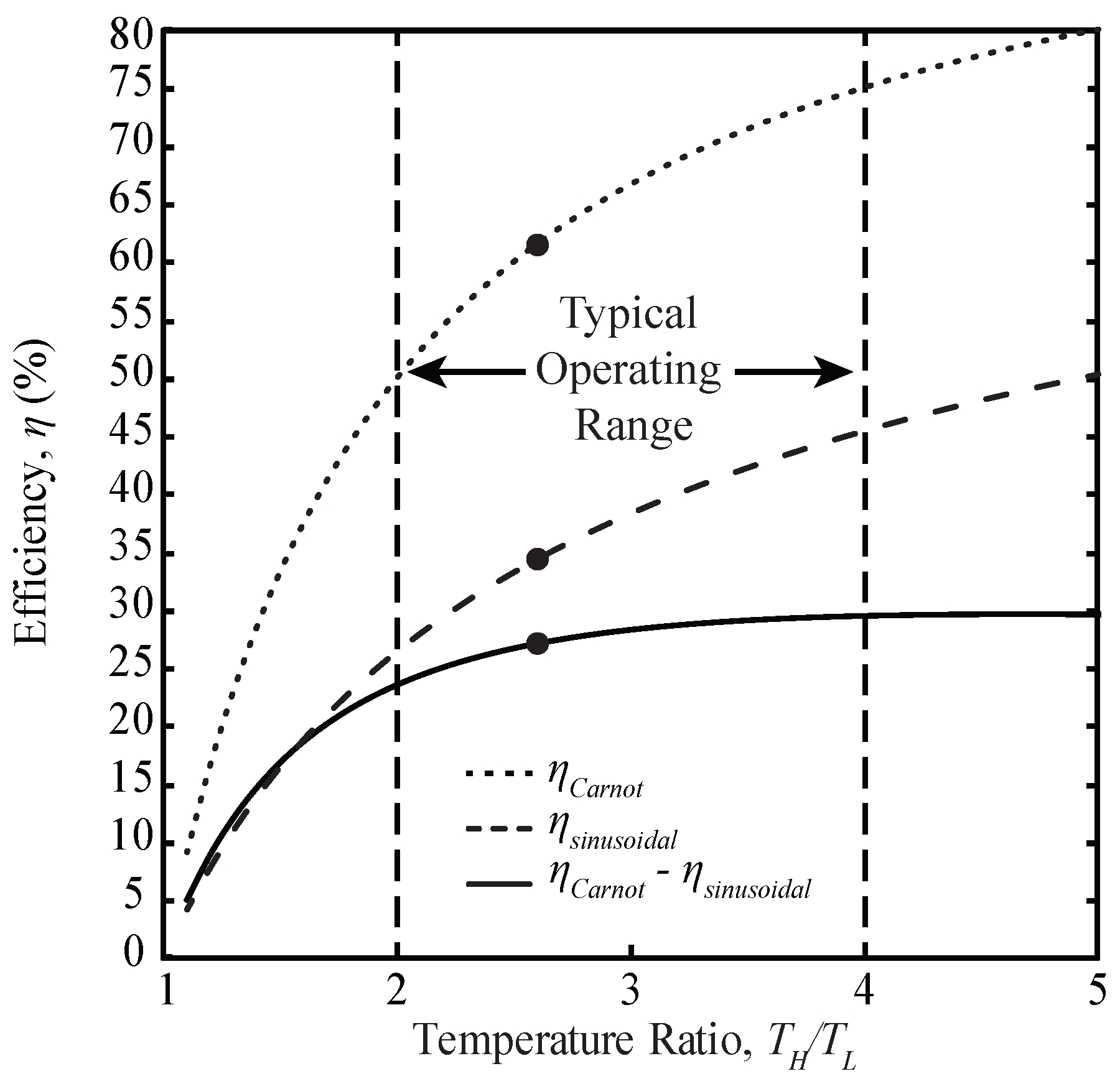
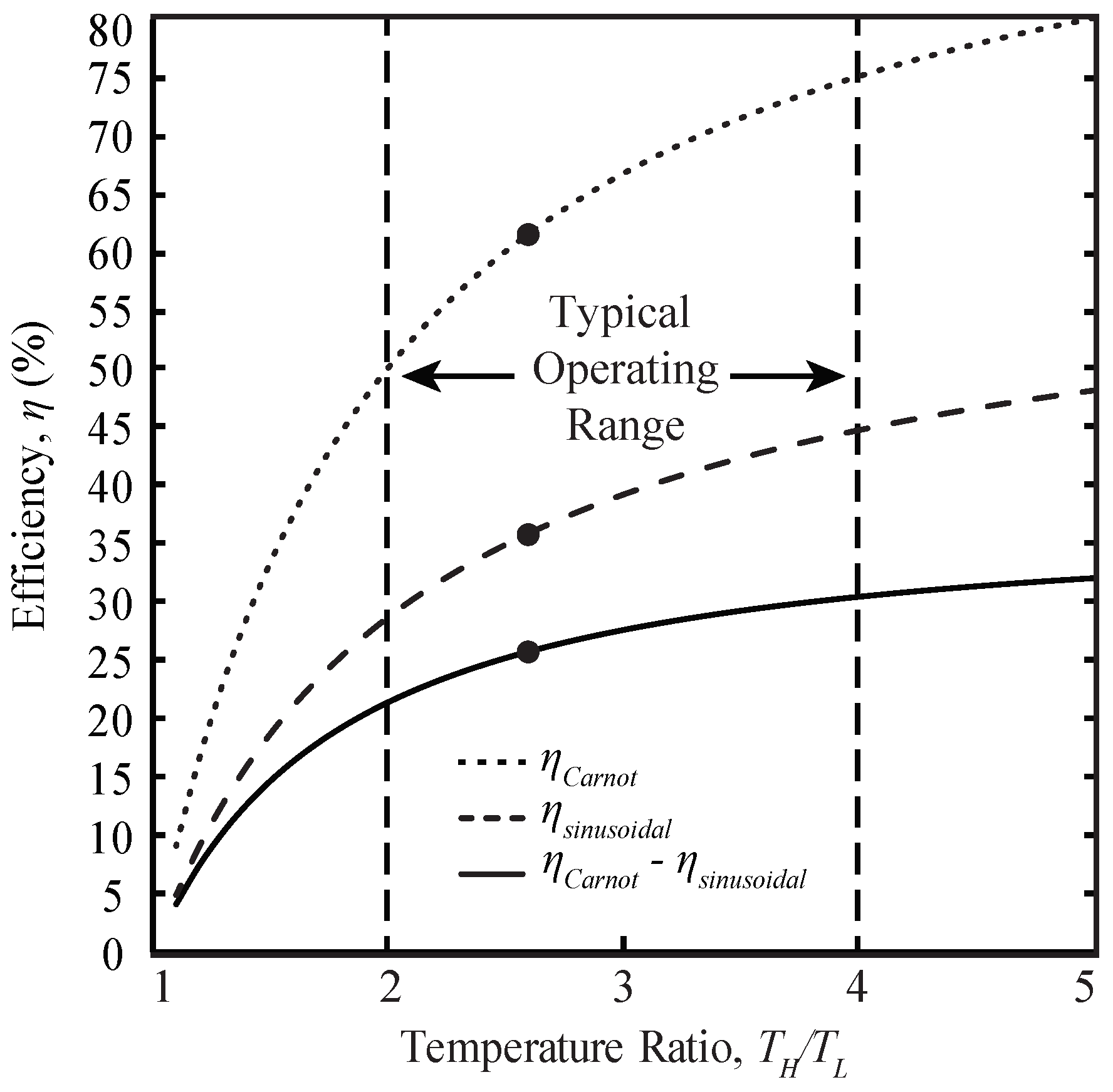
4.3. Deviation from Carnot Efficiency

As shown in Figure 4, and described in Equations (12) and (13), the work output (expansion) corresponds to a required heat input and the work input (compression) corresponds to a required heat output, regardless of the piston where this is occurring. Accordingly, using Equations (12)–(14), and (18), the thermal efficiency can be calculated. In the ideal cycle, this results in a thermal efficiency matching the Carnot efficiency ( η C a r n o t = 1 T L / T H ), which is 61.5% for the values listed in Table 1. For the sinusoidal cycle, the resulting thermal efficiency is 34.4%, which corresponds to a reduction of 27.1% from the maximum attainable efficiency.
Since the efficiency is strongly influenced by the temperature ratio, we calculate the efficiency for various temperature ratios to illustrate the deviation resulting from the sinusoidal cycle across a broad range of temperature ratios, as shown in Figure 5. Typically, a Stirling engine operates with a temperature ratio between 2 and 4, due to the material limitations, available heat sinks and fuel sources. Within these temperature bounds, the effect of sinusoidal operation on alpha-Stirling engines is reasonably constant since the resultant reduction in thermal efficiencies ranges from 23.6% to 29.5%, as seen in Figure 5. This represents a substantial reduction in efficiency versus the theoretical efficiency and helps to explain why practical engines with sinusoidal motion have low efficiencies. Operation with sinusoidal motion inherently limits the maximum attainable efficiency, and thus practical Stirling engines operating with sinusoidal motion should be compared against this maximum efficiency for sinusoidal operation as opposed to the Carnot efficiency.

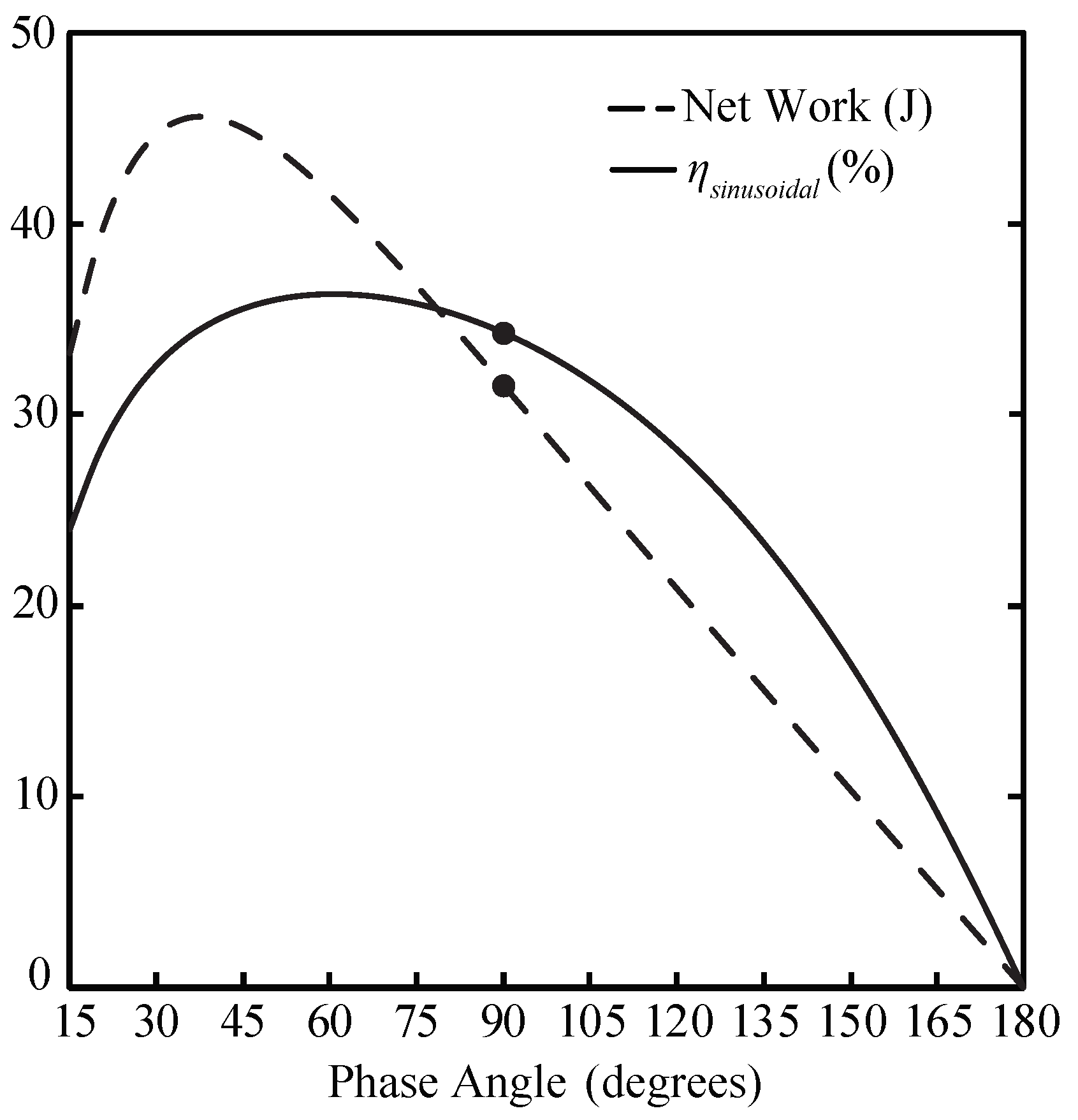
4.4. Phase Angle Dependency for a Sinusoidal Alpha-Type Stirling Engine

Alpha-type Stirling engines operating on a sinusoidal cycle can use a variety of phase angles, α , which alters the expansion and compression characteristics and affects the maximum net work and attainable thermal efficiency for the system [19]. Based on our analysis, we plot the net work and thermal efficiency versus the phase angle in Figure 6, and illustrate how the phase angle influences the values. As seen in Figure 6, the phase angle that produces the maximum net work is 40 , which confirms the findings from past studies [19], producing 45.6 J per cycle, based on the values listed in Table 1. Our analysis reveals that a phase angle of 60 corresponds to the largest attainable thermal efficiency, with a value of 36.4%. This is a small improvement over a phase angle of 90 , but ultimately still represents a substantial reduction versus the theoretical (Carnot) efficiency.

4.5. Effects of Sinusoidal Operation on Beta-Type and Gamma-Type Stirling Engines

The previous analysis was performed specifically for an alpha-type Stirling engine, as shown in Figure 1. However, the effects of sinusoidal operation are not limited only to the alpha configuration. The beta and gamma-type Stirling engines are also common configurations [24]. Both the beta and gamma differ from the alpha configuration by their volumetric constraints, illustrated in Figure 7. While the hot volume remains identical to the alpha, the cold volume is not only constrained to sinusoidal movement with a phase angle shift, but also includes the relative location of the hot displacer or piston. This is accounted for by a change in Equations (2) and (3) as follows:
V H ( θ ) = V H , m a x 2 ( 1 cos θ ) + V D H ,
V C ( θ ) = V H , m a x 2 ( 1 + cos θ ) + V C , m a x 2 ( 1 cos ( θ α ) ) + V D C .
These equations describe both the beta and gamma cycles, so the following analysis applies to both types. The other thermodynamic properties and equations stay the same as the alpha Stirling approach.
The ideal beta and gamma Stirling cycles and the sinusoidal cycles are shown on the P-v and T-s diagrams in Figure 8. The gray shaded regions show the areas of thermodynamic deviation due to sinusoidal operation that generate a reduction from the maximum potential net work and thermal efficiency. This is a result of the continuous sinusoidal movement of the hot and cold pistons and the inability to follow the ideal cycle, similar to the alpha-type Stirling engine, as detailed in the previous sections.
By applying Equations (12)–(14), and (18), and adapting them to apply to the volumetric variations of the beta/gamma configuration with a power piston and displacer setup according to Equations (19) and (20), and using the values listed in Table 1, the thermal efficiency was found to be 35.8%, which is a reduction of 25.7% from the Carnot efficiency. Similar to the alpha-type engine, the efficiency depends on the temperature ratios, so the resulting efficiency is plotted for a range of temperature ratios in Figure 9. Within the typical operating range described above, the effects of sinusoidal operation on beta and gamma Stirling engines results in a reduction in thermal efficiencies ranging from 21.4% to 30.4%, as seen in Figure 9. Our findings thus demonstrate that sinusoidal operation impacts all Stirling configurations in a similarly adverse manner.

5. Conclusions

A comprehensive discretized model of an alpha-type Stirling engine was developed to investigate the deviations resulting from sinusoidal operation. The deviation of the sinusoidal cycle from the ideal cycle results in a reduction in the attainable work and a reduction in the attainable thermal efficiency. We analyzed a specific engine and found that due to the sinusoidal motion, the alpha-type Stirling engine was only able to produce 65.9% of the ideal work. The resulting thermal efficiency was 34.4%, which corresponded to a reduction of 27.1% from the maximum attainable Carnot efficiency. Within typical operating temperature ratios of 2 to 4, the reduction in thermal efficiencies ranged from 23.6% to 29.5% respectively. For the case we investigated, our analysis also revealed that a phase angle of 60 corresponded to the largest attainable thermal efficiency, with a value of 36.4%. For beta and gamma-type Stirling engines, the thermal efficiency was found to be 35.8%, which corresponded to a reduction of 25.7% from the maximum attainable Carnot efficiency. Similar to the alpha-type engine, within the typical operating temperature ratios of 2 to 4, the reduction in thermal efficiencies ranged from 21.4% to 30.4% respectively. We have shown that sinusoidal operation impacts alpha, beta, and gamma Stirling configurations in a similarly adverse manner.
The finding of sinusoidal motion generating a substantial reduction in efficiency versus the theoretical efficiency helps to explain why practical Stirling engines operating with sinusoidal motion have efficiency values substantially below the reduced amount caused by typical mechanical losses alone. Operation with sinusoidal motion inherently limits the maximum attainable efficiency, and thus Stirling engines operating with sinusoidal motion should be compared against the maximum efficiency for the sinusoidal cycle instead of the Carnot efficiency.

Author Contributions

B.D.M. conceived of the idea for the paper and supervised all of the work. G.A.O.P. performed the initial discretization and contributed ideas about mass calculation. S.R. performed the thermodynamic analysis and contributed ideas about how to organize and present the findings. All authors contributed to writing and editing the paper.

Funding

The authors gratefully acknowledge the funding support from Transport Canada through a Clean Rail Academic Grant, and from a Natural Sciences and Engineering Research Council of Canada (NSERC) Idea-to-Innovation grant.

Conflicts of Interest

The authors declare no conflict of interest.

Nomenclature

V H hot volume (cm 3 )
V C cold volume (cm 3 )
V R regenerator volume (cm 3 )
V t o t a l total volume of working fluid (cm 3 )
V D H hot space dead volume (cm 3 )
V D C cold space dead volume (cm 3 )
m s y s t e m total mass of working fluid (kg)
m H mass of working fluid within hot volume (kg)
m C mass of working fluid within cold volume (kg)
m R mass of working fluid within regenerator (kg)
vspecific volume (m 3 /kg)
Pengine pressure (kPa)
Rgas constant (J/kg K)
T H hot temperature (K)
T C cold temperature (K)
T R regenerator temperature (K)
T g l o b a l total average temperature (K)
sspecific entropy (J/kg K)
W H work from hot piston (J)
W C work from cold piston (J)
W n e t total work produced (J)
Q i n heat addition (J)
Q o u t heat rejection (J)
α phase angle ( )
η t h thermal efficiency
θ crank angle ( )

References

  1. Cengel, Y.; Boles, M. Thermodynamics: An Engineering Approach, 8th ed.; McGraw-Hill Education: New York, NY, USA, 2015. [Google Scholar]
  2. Kim, Y.; Chun, W.; Chen, K. Thermal-Flow Analysis of a Simple LTD (Low-Temperature-Differential) Heat Engine. Energies 2017, 10, 567. [Google Scholar] [CrossRef]
  3. Martini, W.R. Stirling Engine Design Manual; US Department of Energy, Office of Conservation and Solar Applications, Division of Transportation Energy Conservation: Washington, DC, USA, 1978.
  4. Wu, F.; Chen, L.; Wu, C.; Sun, F. Optimum performance of irreversible Stirling engine with imperfect regeneration. Energy Convers. Manag. 1998, 39, 727–732. [Google Scholar] [CrossRef]
  5. Isshiki, S.; Sakano, A.; Ushiyama, I.; Isshiki, N. Studies on flow resistance and heat transfer of regenerator wire meshes of Stirling engine in oscillatory flow. JSME Int J. Ser. B 1997, 40, 281–289. [Google Scholar] [CrossRef]
  6. Muralidhar, K.; Suzuki, K. Analysis of flow and heat transfer in a regenerator mesh using a non-Darcy thermally non-equilibrium model. Int. J. Heat Mass Transf. 2001, 44, 2493–2504. [Google Scholar] [CrossRef]
  7. Kongtragool, B.; Wongwises, S. Thermodynamic analysis of a Stirling engine including dead volumes of hot space, cold space and regenerator. Renew. Energy 2006, 31, 345–359. [Google Scholar] [CrossRef]
  8. Wang, K.; Sanders, S.R.; Dubey, S.; Choo, F.H.; Duan, F. Stirling cycle engines for recovering low and moderate temperature heat: A review. Renew. Sustain. Energy Rev. 2016, 62, 89–108. [Google Scholar] [CrossRef]
  9. Briggs, M. Improving Free-Piston Stirling Engine Power Density. Ph.D. Thesis, Case Western Reserve University, Cleveland, OH, USA, 2015. [Google Scholar]
  10. Sowale, A.; Kolios, A.J. Thermodynamic Performance of Heat Exchangers in a Free Piston Stirling Engine. Energies 2018, 11, 505. [Google Scholar] [CrossRef]
  11. Schmidt, G. The theory of Lehmann’s calorimetric machine. Z. Ver. Dtsch. Ing. 1871, 15 Pt I. [Google Scholar]
  12. Thombare, D.; Verma, S. Technological development in the Stirling cycle engines. Renew. Sustain. Energy Rev. 2008, 12, 1–38. [Google Scholar] [CrossRef]
  13. Finkelstein, T. Generalized Thermodynamic Analysis of Stirling Engines; SAE Technical Paper: Warrendale, PA, USA, January 1960. [Google Scholar] [CrossRef]
  14. Walker, G. An optimization of the principal design parameters of Stirling cycle machines. J. Mech. Eng. Sci. 1962, 4, 226–240. [Google Scholar] [CrossRef]
  15. Kirkley, D. Determination of the optimum configuration for a Stirling engine. J. Mech. Eng. Sci. 1962, 4, 204–212. [Google Scholar] [CrossRef]
  16. Urieli, I.; Berchowitz, D.M. Stirling Cycle Engine Analysis; Taylor & Francis: Milton Park, UK, 1984. [Google Scholar]
  17. Senft, J.R. Optimum Stirling engine geometry. Int. J. Energ. Res. 2002, 26, 1087–1101. [Google Scholar] [CrossRef]
  18. Cheng, C.H.; Yu, Y.J. Dynamic simulation of a beta-type Stirling engine with cam-drive mechanism via the combination of the thermodynamic and dynamic models. Renew. Energy 2011, 36, 714–725. [Google Scholar] [CrossRef]
  19. Cinar, C. Thermodynamic analysis of an α-type Stirling engine with variable phase angle. Proc. Inst. Mech. Eng. Part C J. Mech. Eng. Sci. 2007, 221, 949–954. [Google Scholar] [CrossRef]
  20. Tlili, I.; Timoumi, Y.; Nasrallah, S.B. Analysis and design consideration of mean temperature differential Stirling engine for solar application. Renew. Energy 2008, 33, 1911–1921. [Google Scholar] [CrossRef]
  21. Formosa, F.; Despesse, G. Analytical model for Stirling cycle machine design. Energy Convers. Manag. 2010, 51, 1855–1863. [Google Scholar] [CrossRef] [Green Version]
  22. Cheng, C.H.; Yang, H.S. Optimization of geometrical parameters for Stirling engines based on theoretical analysis. Appl. Energy 2012, 92, 395–405. [Google Scholar] [CrossRef]
  23. Alfarawi, S.; Al-Dadah, R.; Mahmoud, S. Influence of phase angle and dead volume on gamma-type Stirling engine power using CFD simulation. Energy Convers. Manag. 2016, 124, 130–140. [Google Scholar] [CrossRef]
  24. Egas, J.; Clucas, D.M. Stirling Engine Configuration Selection. Energies 2018, 11, 584. [Google Scholar] [CrossRef]
Figure 1. Schematic of an alpha-type Stirling engine.
Energies 11 02887 g001
Figure 2. Sinusoidal and ideal cycle plots in (a) P-v and (b) T-s diagrams for the modeled alpha-type Stirling engine.
Energies 11 02887 g002
Figure 3. (a) Volume and (b) mass of the sinusoidal cycle as a function of crank angle ( θ ), for the alpha-type Stirling engine.
Energies 11 02887 g003
Figure 4. Work in the (a) hot cylinder and (b) cold cylinder versus crank angle ( θ ) for the alpha-type Stirling engine. The W o u t corresponds to Q i n and is shown as red, and the W i n corresponds to Q o u t and is shown as blue.
Energies 11 02887 g004
Figure 5. Efficiencies for Carnot, the sinusoidal cycle, and the deviation between them for an alpha-type Stirling engine at various temperature ratios. The points indicate the values for the engine details provided in Table 1.
Energies 11 02887 g005
Figure 6. Net work and efficiency as a function of phase angle for an alpha-type Stirling engine. The points indicate the values for the engine details provided in Table 1, with a phase angle of 90 .
Energies 11 02887 g006
Figure 7. Schematics of (a) beta-type and (b) gamma-type Stirling engines.
Energies 11 02887 g007
Figure 8. Sinusoidal and ideal cycle plots in (a) P-v and (b) T-s diagrams for the modeled beta and gamma-type Stirling engines.
Energies 11 02887 g008
Figure 9. Efficiencies for Carnot, the sinusoidal cycle, and the deviation between them for both beta and gamma-type Stirling engines at various temperature ratios. The point indicates the values corresponding to the engine details provided in Table 1.
Energies 11 02887 g009
Table 1. Details of the engine used in the analysis.
ParameterValue
Working FluidAir
Cold Swept Volume (cm 3 )100
Hot Swept Volume (cm 3 )100
Charge Pressure (kPa)101.325
Regenerator/passage volume (cm 3 )2
Total dead volume (cm 3 )2
Hot Volume temperature (K)773.15
Cold Volume temperature (K)298.15
Table 2. Summary of work during each process for the alpha-type Stirling engine.
Crank Angle Range ( θ )ProcessWork Summation Value (J)
Cold Piston WorkHot Piston Work
0 90 Isochoric regeneration−32.643.0
90 180 Isothermal expansion16.324.9
180 270 Isochoric regeneration8.0−7.4
270 360 Isothermal compression−11.5−9.1
Total−19.951.5
Net Work31.6

