A Quasi-Resonant ZVZCS Phase-Shifted Full-Bridge Converter with an Active Clamp in the Secondary Side


Abstract
:1. Introduction
- ▪
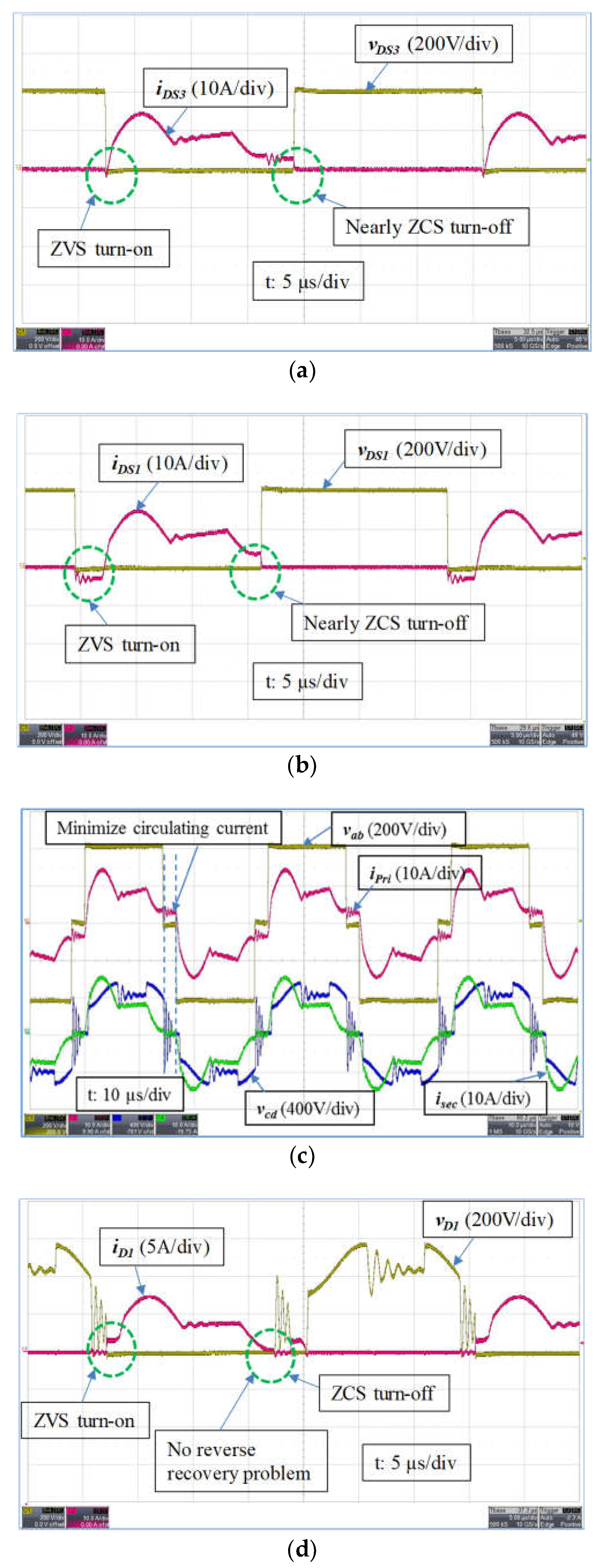
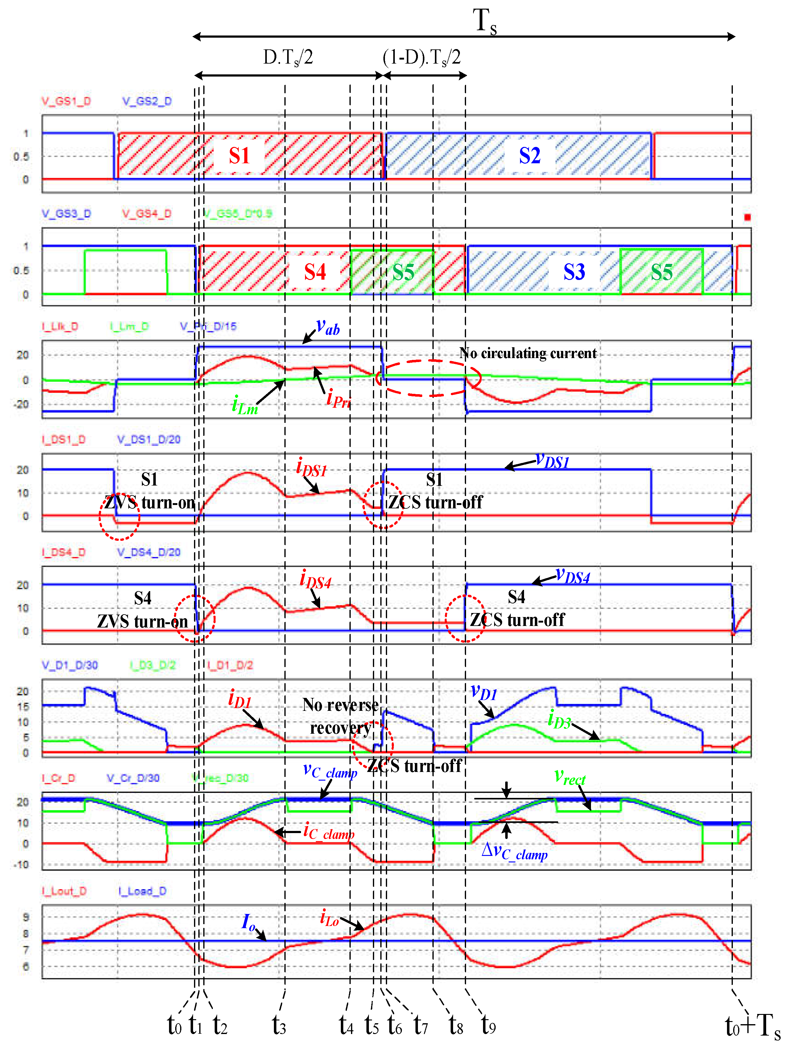
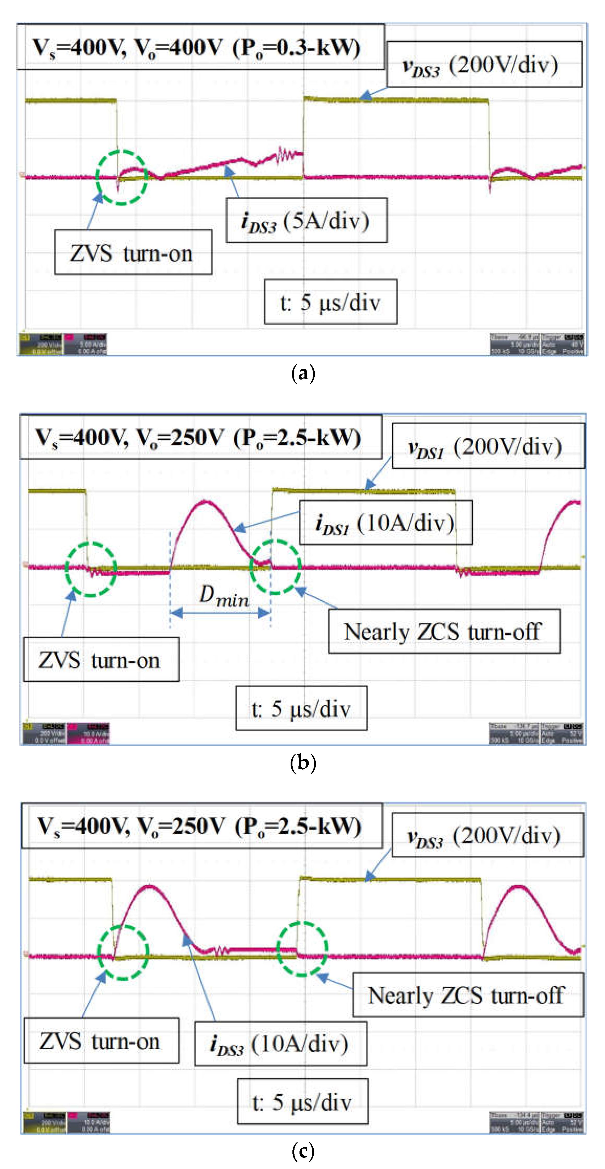
- ZVS turn-on for all of the primary switches over the entire load range.
- ▪
- Nearly ZCS turn-off for all of the primary switches over the entire load range.
- ▪
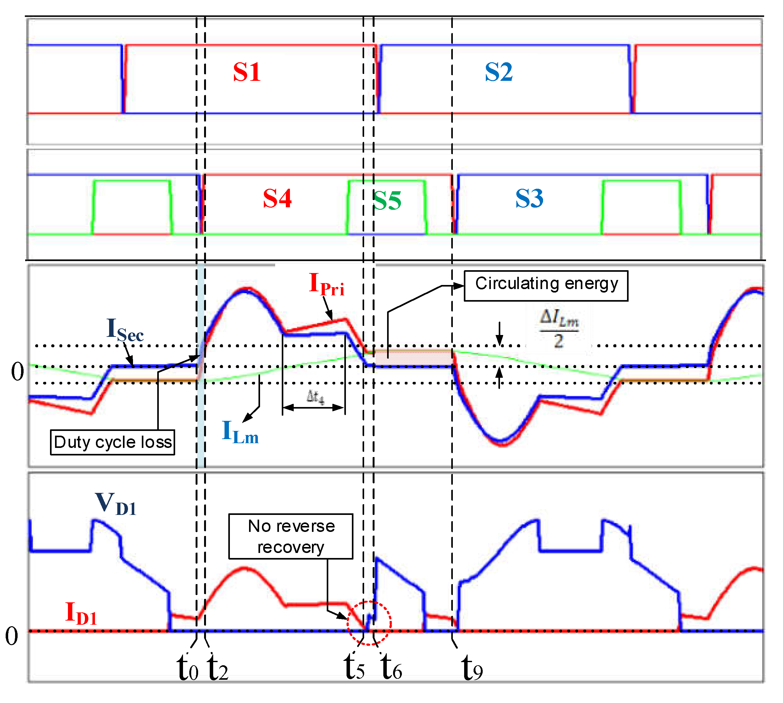
- Complete elimination of the circulating current during freewheeling, which eliminates its associated losses.
- ▪
- No reverse recovery for the secondary rectifier diodes.
- ▪
- Little duty cycle loss.
- ▪
- Elimination of the voltage ringing at the secondary circuit.
- ▪
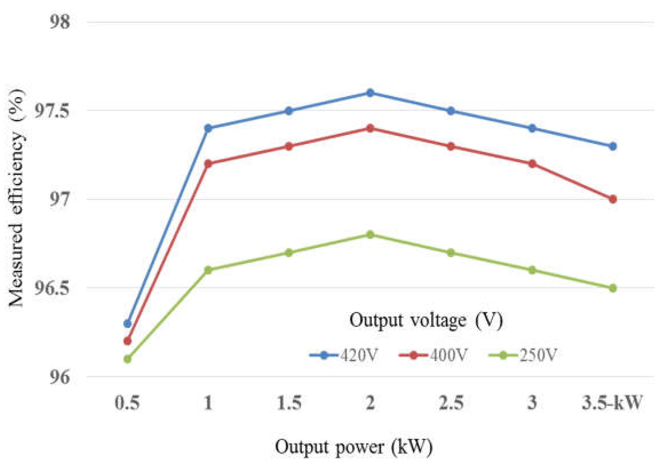
- High efficiency over the entire load range.
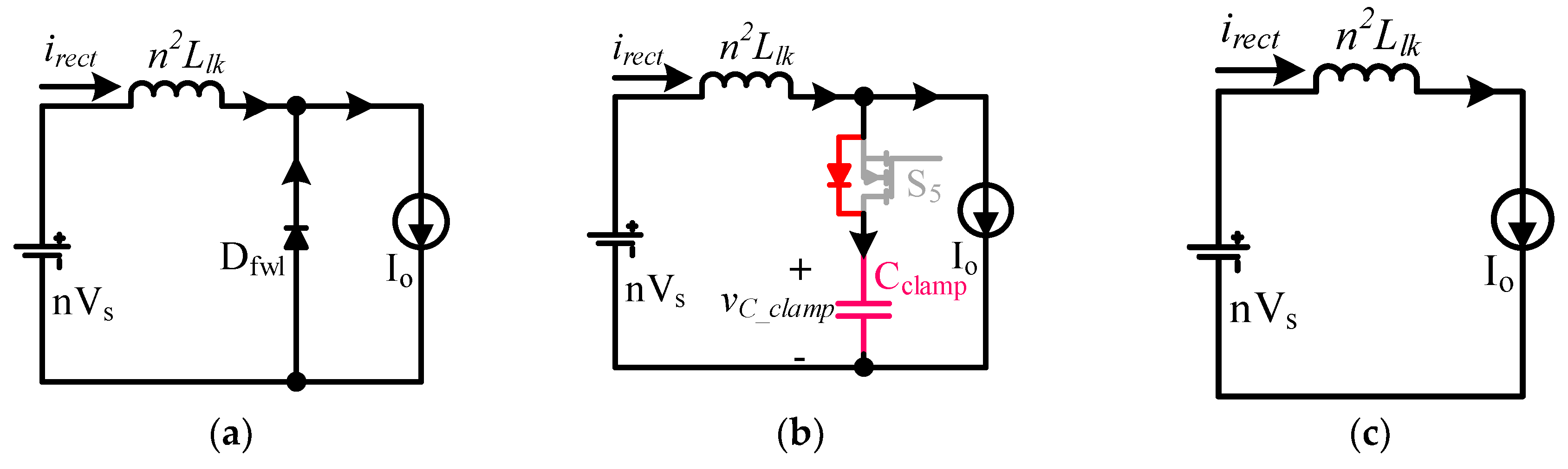
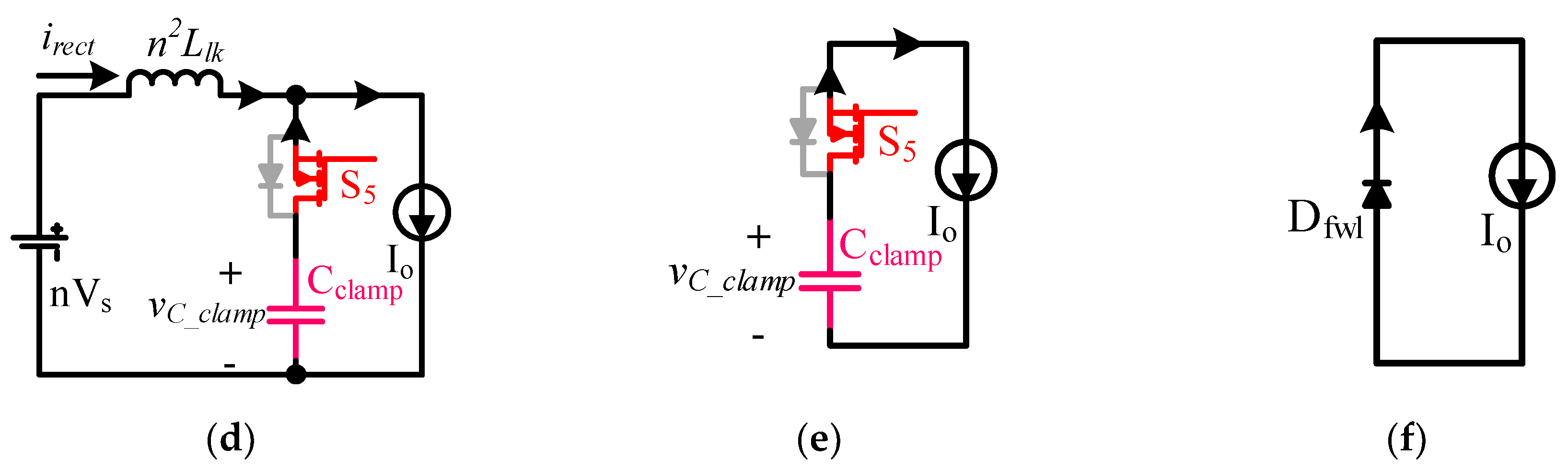
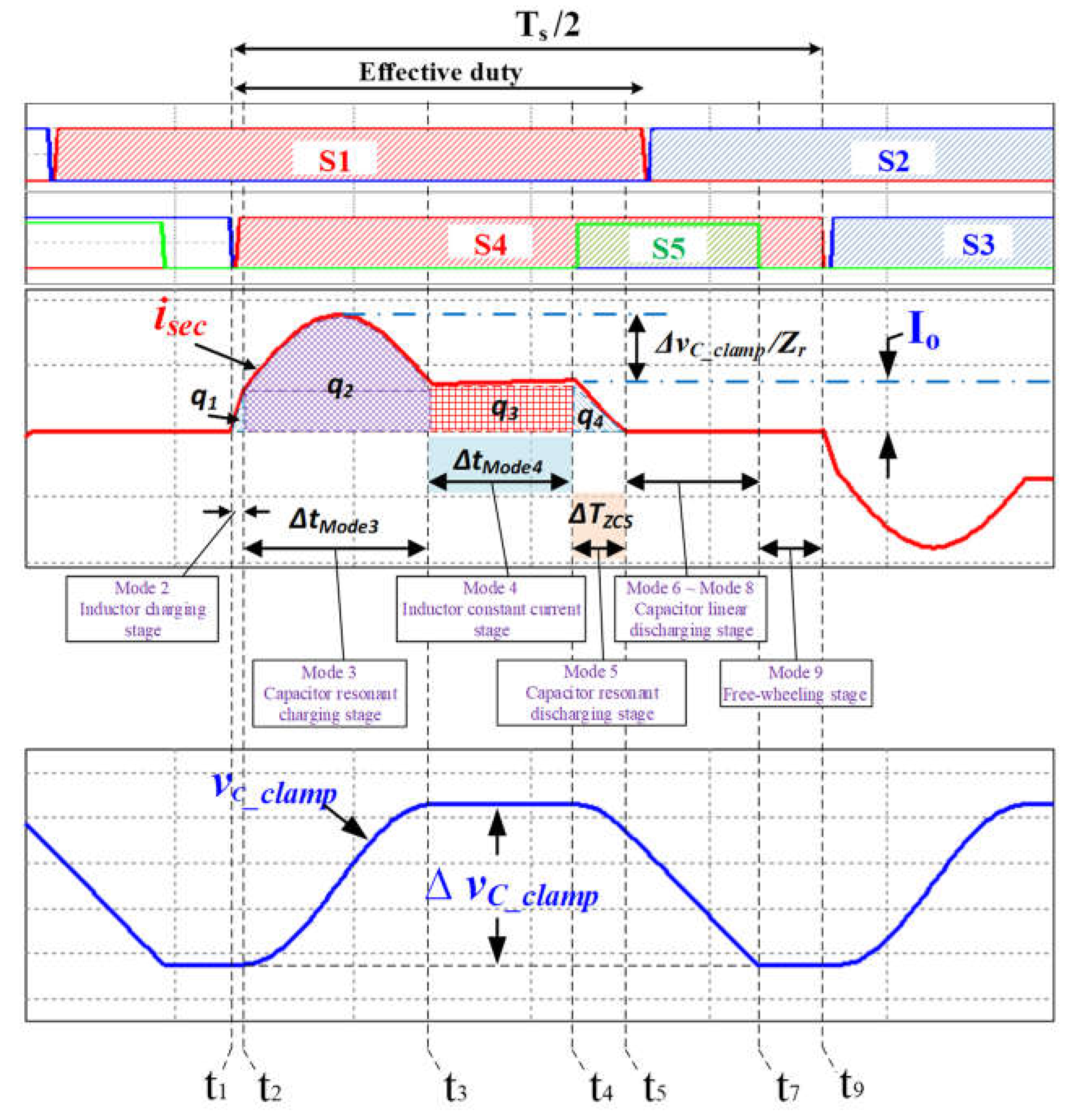
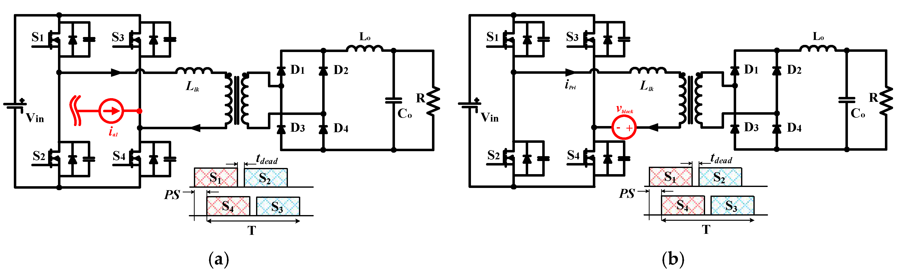
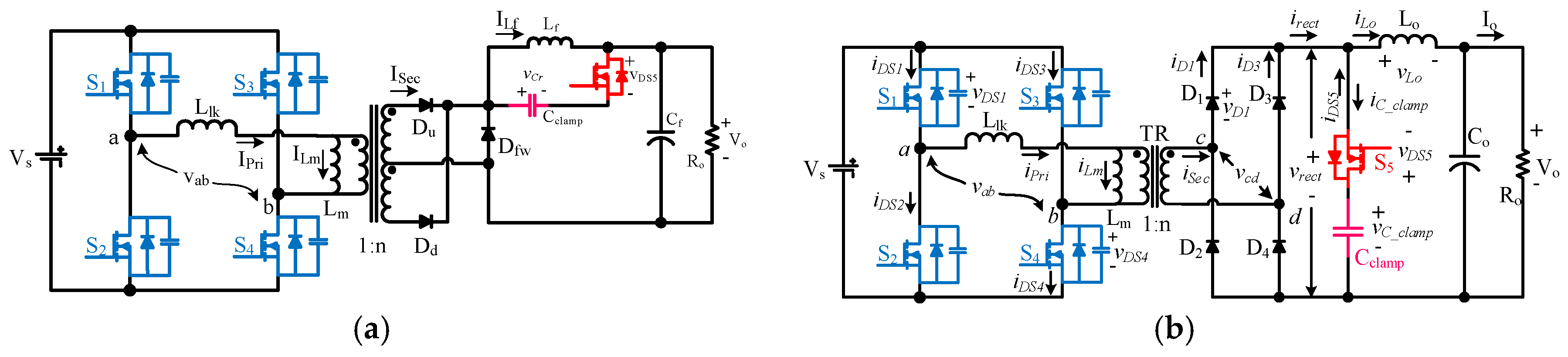
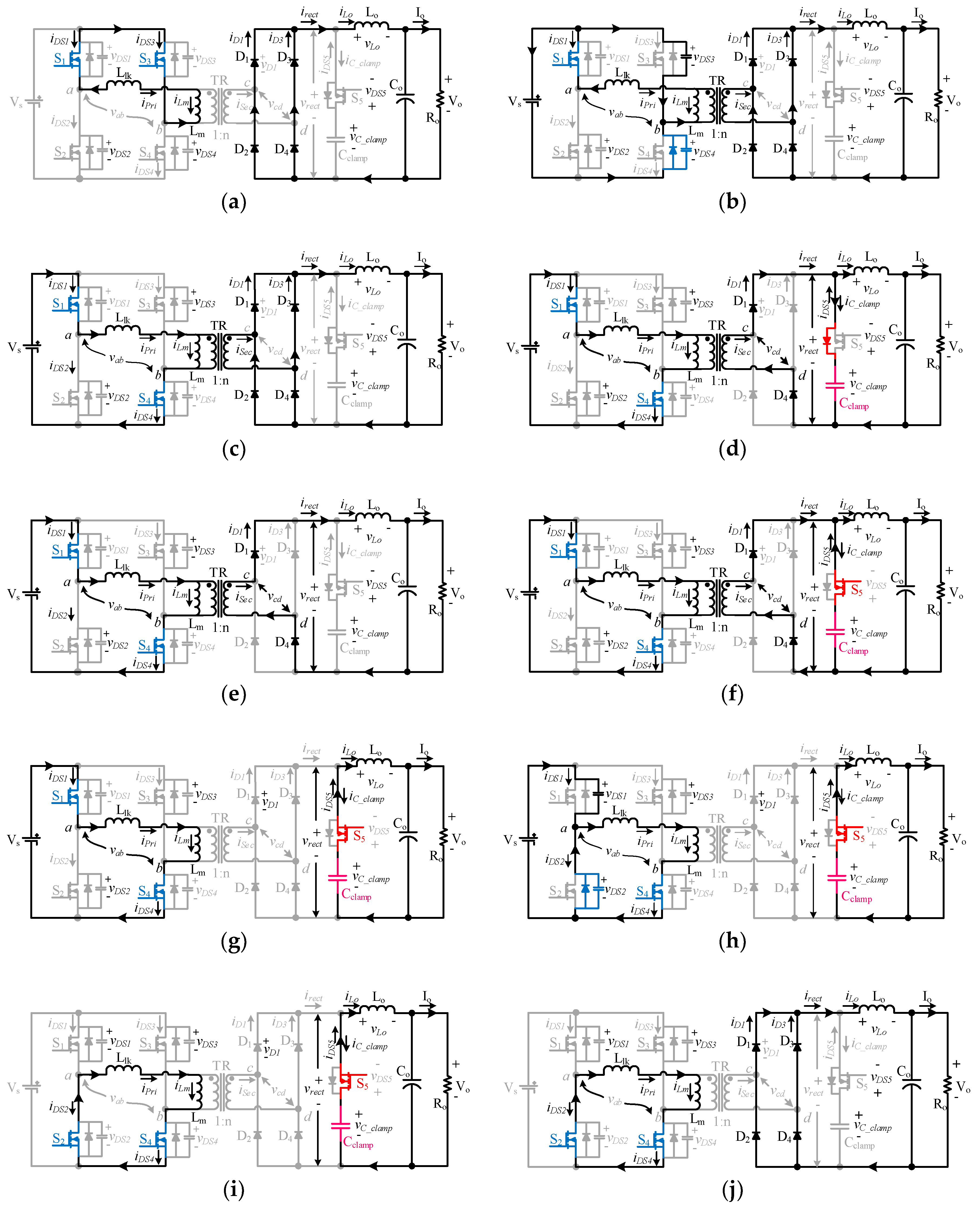
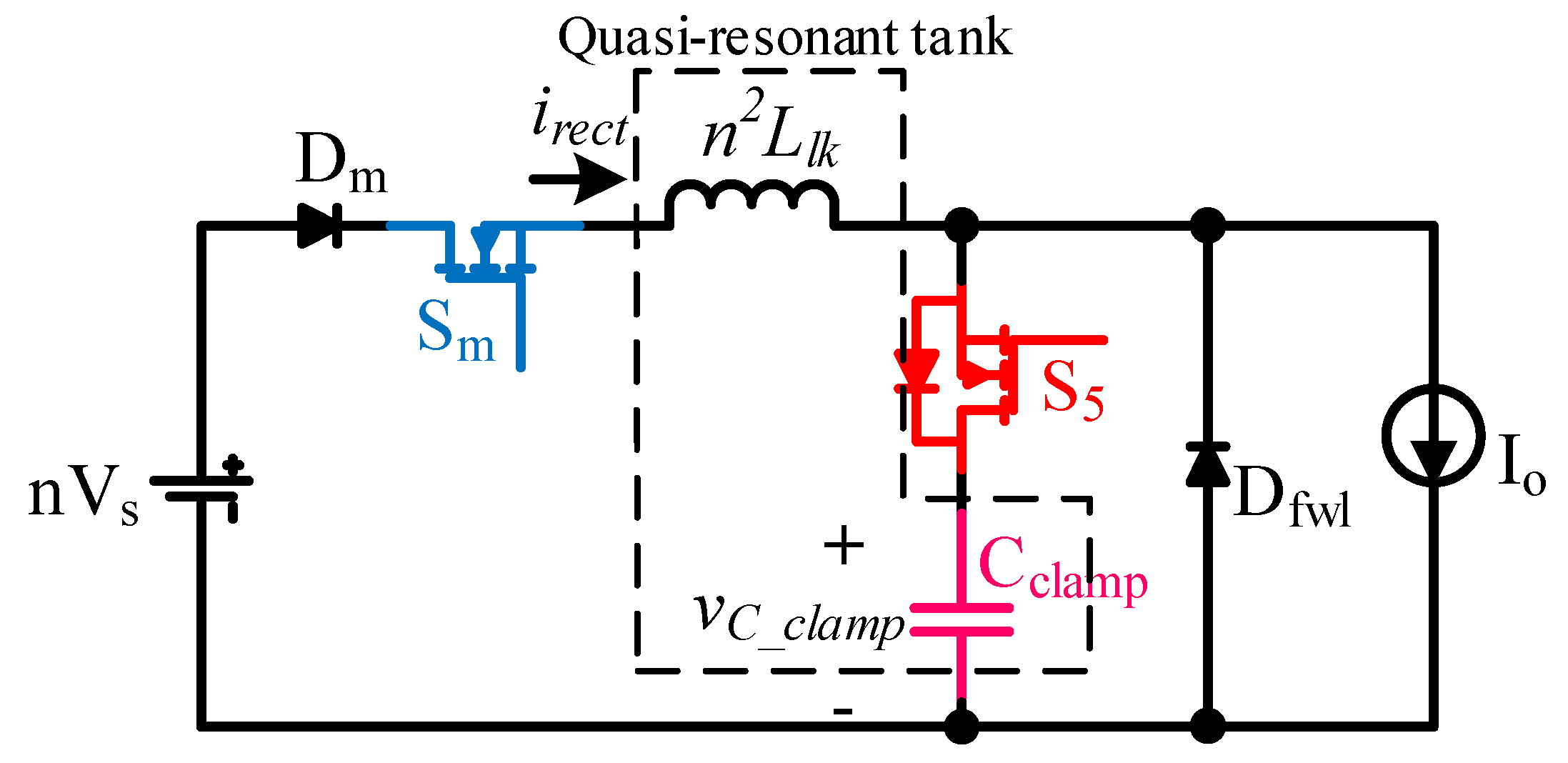
2. Operational Principle of the Proposed Quasi-Resonant ZVZCS PSFB Converter
- ▪
- Characteristic impedance
- ▪
- Resonant angular frequency
- ▪
- Resonant frequency
- ▪
- Switching period Ts and switching frequency fs
3. Analysis of the Proposed Converter
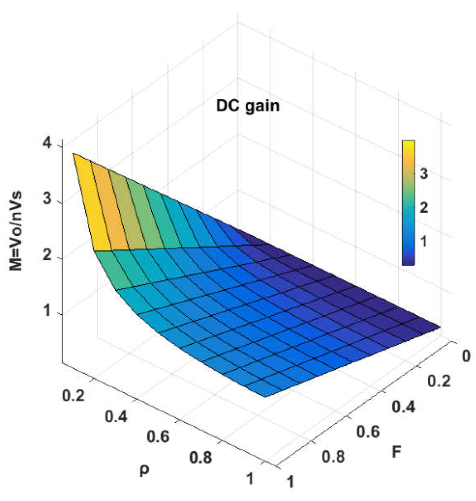
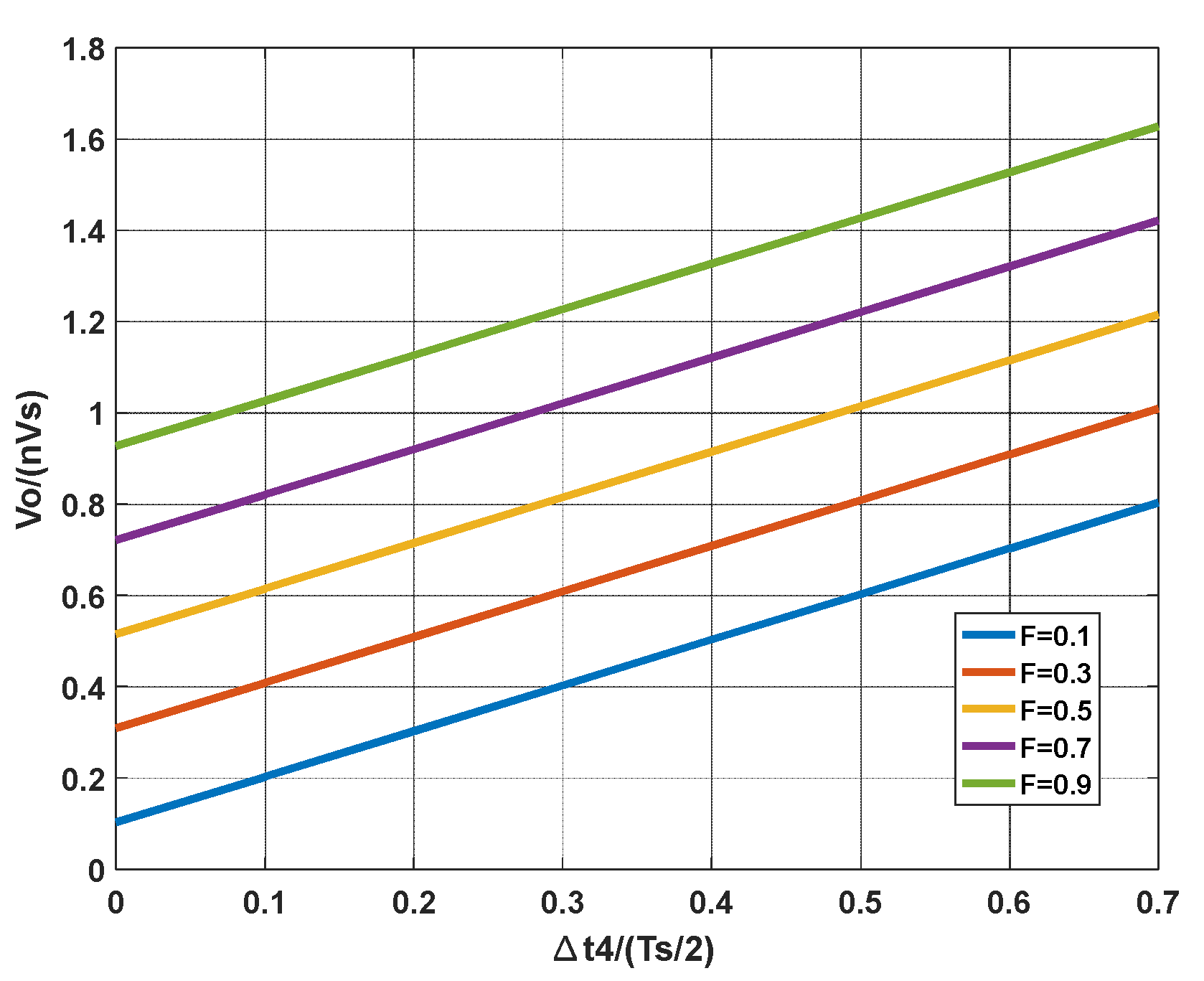
3.1. Voltage Conversion Ratio
3.2. ZVS Turn-On for All Primary Switches Regardless of the Load
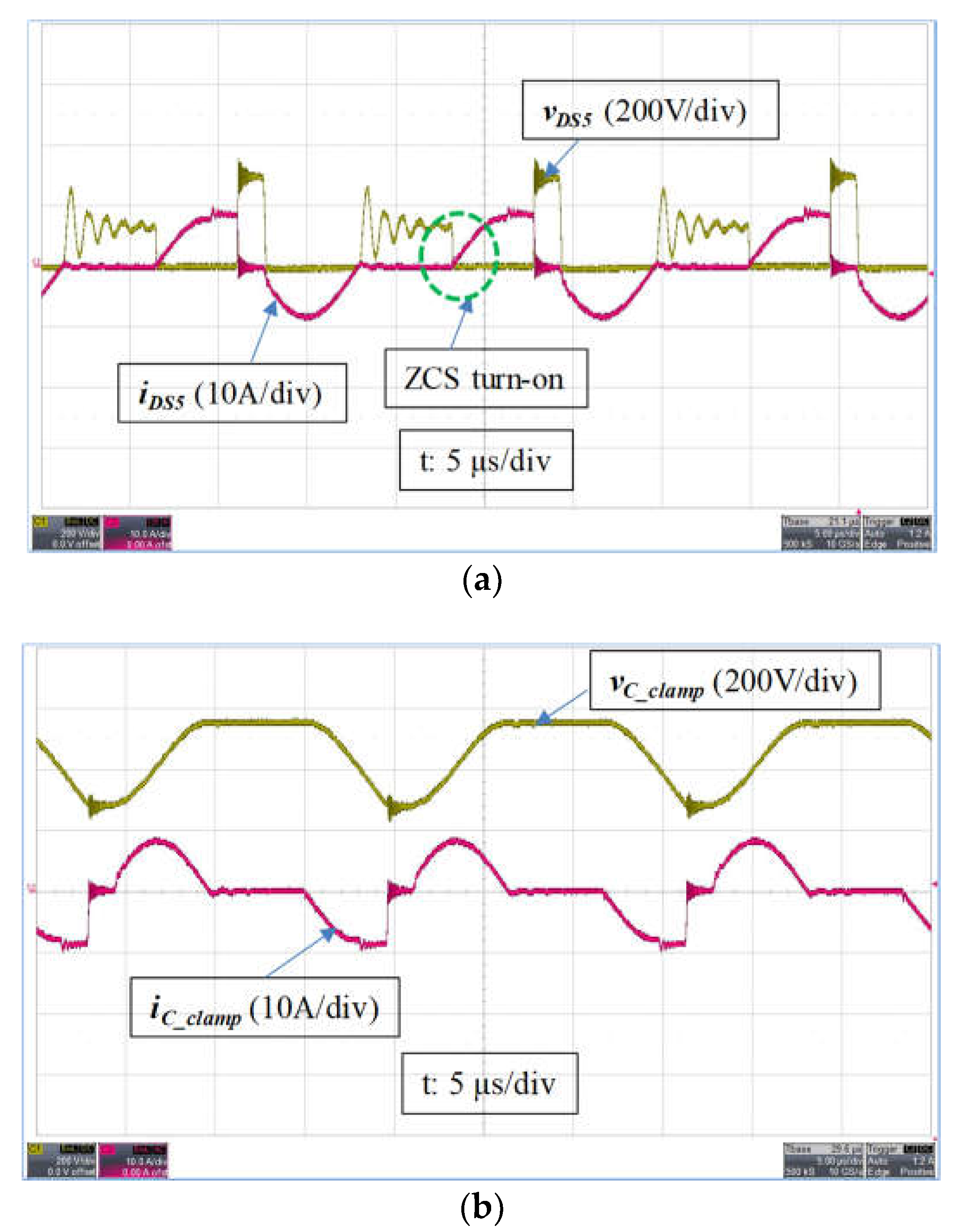
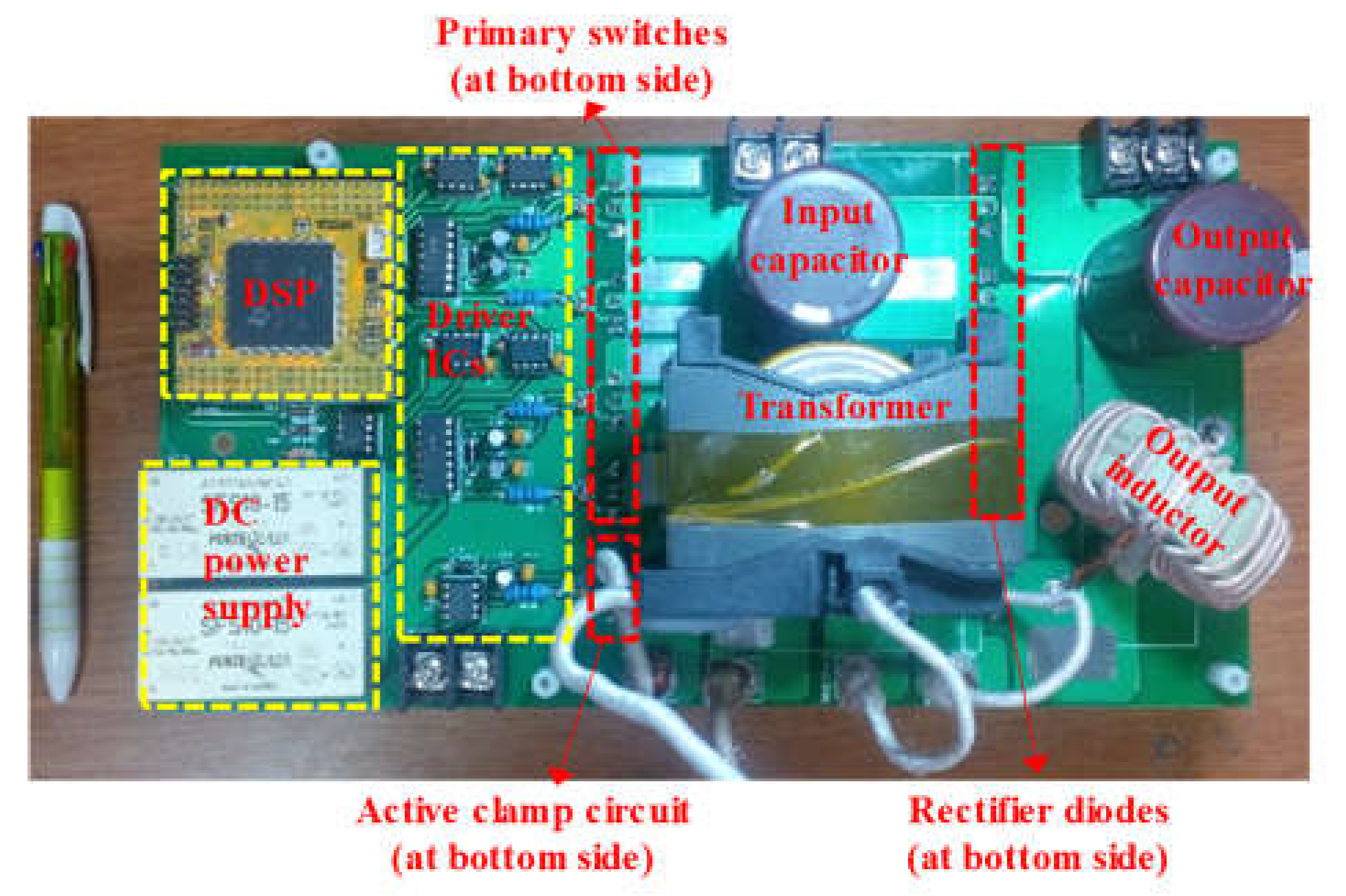
4. Experimental Results
5. Conclusions
Author Contributions
Funding
Acknowledgments
Conflicts of Interest
Appendix A
References
- Aharon, I.; Kuperman, A. Topological overview of powertrains for battery-powered vehicles with range extenders. IEEE Trans. Power Electron. 2011, 26, 868–876. [Google Scholar] [CrossRef]
- Chen, Z.; Ji, B.; Ji, F.; Shi, L. Analysis and Design Considerations of an Improved ZVS Full-Bridge DC-DC Converter. In Proceedings of the 2010 Twenty-Fifth Annual IEEE Applied Power Electronics Conference and Exposition (APEC), Palm Springs, CA, USA, 21–25 February 2010; pp. 1471–1476. [Google Scholar]
- Chen, Z.; Liu, S.S.; Wang, Y.; Shi, L.C. Soft Switching Full-Bridge Converter with a Wide ZVS Range and Reduced Parasitic Oscillation. In Proceedings of the 2013 IEEE Energy Conversion Congress and Exposition (ECCE), Denver, CO, USA, 15–19 September 2013; pp. 5440–5447. [Google Scholar]
- Sun, C.; Li, X.D. Fast transient modulation for a step load change in a dual-active-bridge converter with extended-phase-shift control. Energies 2018, 11, 1569. [Google Scholar] [CrossRef]
- Xu, W.Z.; Chan, N.H.L.; Or, S.W.; Ho, S.L.; Chan, K.W. A new control method for a bi-directional phase-shift-controlled DC-DC converter with an extended load range. Energies 2017, 10, 1532. [Google Scholar] [CrossRef]
- Hsieh, Y.C.; Huang, C.S. Li-ion battery charger based on digitally controlled phase-shifted full-bridge converter. IET Power Electron. 2011, 4, 242–247. [Google Scholar] [CrossRef]
- Tran, D.D.; Vu, H.N.; Yu, S.; Choi, W. A novel soft-switching full-bridge converter with a combination of a secondary switch and a nondissipative snubber. IEEE Trans. Power Electron. 2018, 33, 1440–1452. [Google Scholar] [CrossRef]
- Kim, J.H.; Lee, I.O.; Moon, G.W. Integrated dual full-bridge converter with current-doubler rectifier for ev charger. IEEE Trans. Power Electron. 2016, 31, 942–951. [Google Scholar] [CrossRef]
- Kim, T.H.; Lee, S.J.; Choi, W. Design and control of the phase shift full bridge converter for the on-board battery charger of electric forklifts. J. Power Electron. 2012, 12, 113–119. [Google Scholar] [CrossRef]
- Lee, I.O.; Moon, G.W. Analysis and design of phase-shifted dual H-bridge converter with a wide ZVS range and reduced output filter. IEEE Trans. Ind. Electron. 2013, 60, 4415–4426. [Google Scholar] [CrossRef]
- Lee, I.O.; Moon, G.W. Phase-shifted PWM converter with a wide ZVS range and reduced circulating current. IEEE Trans. Power Electron. 2013, 28, 908–919. [Google Scholar] [CrossRef]
- Liu, C.; Gu, B.; Lai, J.S.; Wang, M.Y.; Ji, Y.C.; Cai, G.W.; Zhao, Z.; Chen, C.L.; Zheng, C.; Sun, P.W. High-efficiency hybrid full-bridge-half-bridge converter with shared ZVS lagging leg and dual outputs in series. IEEE Trans. Power Electron. 2013, 28, 849–861. [Google Scholar] [CrossRef]
- Pahlevaninezhad, M.; Das, P.; Drobnik, J.; Jain, P.K.; Bakhshai, A. A Novel ZVZCS full-bridge DC/DC converter used for electric vehicles. IEEE Trans. Power Electron. 2012, 27, 2752–2769. [Google Scholar] [CrossRef]
- Wu, X.K.; Xie, X.G.; Zhao, C.; Qian, Z.M. Low voltage and current stress ZVZCS full bridge DC-DC converter using center tapped rectifier reset. IEEE Trans. Ind. Electron. 2008, 55, 1470–1477. [Google Scholar] [CrossRef]
- Yilmaz, M.; Krein, P.T. Review of battery charger topologies, charging power levels, and infrastructure for plug-in electric and hybrid vehicles. IEEE Trans. Power Electron. 2013, 28, 2151–2169. [Google Scholar] [CrossRef]
- Cacciato, M.; Consoli, A. New Regenerative Active Snubber Circuit for ZVS Phase Shift Full Bridge Converter. In Proceedings of the 2011 Twenty-Sixth Annual IEEE Applied Power Electronics Conference and Exposition (APEC), Fort Worth, TX, USA, 6–11 March 2011; pp. 1507–1511. [Google Scholar]
- Chen, T.F.; Cheng, S. A Novel Zero-Voltage Zero-Current Switching Full-Bridge Pwm Converter Using Improved Secondary Active Clamp. In Proceedings of the 2006 IEEE International Symposium on Industrial Electronics, Montreal, QC, Canada, 9–13 July 2006. [Google Scholar]
- Cho, J.G.; Rim, G.H.; Lee, F.C. Zero voltage and zero current switching full bridge PWM converter using secondary active clamp. IEEE Power Electron. 1996, 13, 657–663. [Google Scholar]
- Cho, J.H.; Park, K.B.; Moon, G.W.; Youn, M.J. A Hybrid PWM Resonant Converter Suitable for Wide Input Variation. In Proceedings of the APEC 2009 Twenty-Fourth Annual IEEE Applied Power Electronics Conference and Exposition, Washington, DC, USA, 15–19 February 2009; pp. 1504–1510. [Google Scholar]
- Dudrik, J.; Trip, N.D. Soft-switching PS-PWM DC-DC converter for full-load range applications. IEEE Trans. Ind. Electron. 2010, 57, 2807–2814. [Google Scholar] [CrossRef]
- Gu, B.; Lai, J.S.; Kees, N.; Zheng, C. Hybrid-switching full-bridge DC-DC converter with minimal voltage stress of bridge rectifier, reduced circulating losses, and filter requirement for electric vehicle battery chargers. IEEE Trans. Power Electron. 2013, 28, 1132–1144. [Google Scholar] [CrossRef]
- Kim, E.H.; Kwon, B.H. Zero-voltage- and zero-current-switching full-bridge converter with secondary resonance. IEEE Trans. Ind. Electron. 2010, 57, 1017–1025. [Google Scholar] [CrossRef]
- Lee, S.H.; Park, C.Y.; Kwon, J.M.; Kwon, B.H. Hybrid-type full-bridge DC/DC converter with high efficiency. IEEE Trans. Power Electron. 2015, 30, 4156–4164. [Google Scholar] [CrossRef]
- Lee, W.J.; Kim, C.E.; Moon, G.W.; Han, S.K. A new phase-shifted full-bridge converter with voltage-doubler-type rectifier for high-efficiency PDP sustaining power module. IEEE Trans. Ind. Electron. 2008, 55, 2450–2458. [Google Scholar] [CrossRef]
- Mousavi, A.; Moschopoulos, G. A New ZCS-PWM full-bridge DC-DC converter with simple auxiliary circuits. IEEE Trans. Power Electron. 2014, 29, 1321–1330. [Google Scholar] [CrossRef]
- Seok, K.W.; Kwon, B.H. An improved zero-voltage and zero-current-switching full-bridge PWM converter using a simple resonant circuit. IEEE Trans. Ind. Electron. 2001, 48, 1205–1209. [Google Scholar] [CrossRef]
- Packnezhad, M.; Farzanehfard, H. A Fully Soft-Switched ZVZCS Full-Bridge PWM Converter. In Proceedings of the 2009 IEEE Symposium on Industrial Electronics & Applications, Kuala Lumpur, Malaysia, 4–6 October 2009; pp. 801–806. [Google Scholar]
- Tran, D.D.; Vu, H.N.; Choi, W. A Novel Quasi-Resonant ZVZCS Phase Shift Full Bridge Converter with an Active Clamp in the Secondary. In Proceedings of the 2016 IEEE 8th International Power Electronics and Motion Control Conference (IPEMC-ECCE Asia), Hefei, China, 22–26 May 2016; pp. 492–495. [Google Scholar]


| Type | Ref | Topology | Soft-Switching Properties | Elimination of Losses | Description of Auxiliary Circuit and Drawbacks. | |||
|---|---|---|---|---|---|---|---|---|
| ZVS Turn-On for Lagging Leg | ZCS Turn-Off for Leading Leg | Circulating Current | Reverse Recovery Current | Duty Cycle Loss | ||||
| Passive clamp [16] | [16] | Resonant CDD with 3 modes | ✔ | - | ~90% | ✔ | ✔ | - Clamp circuit: 1 capacitor and 2 diodes. - Hard-switching turn-off for leading-leg switches. |
| [13] | Resonant CDD with 1 mode | ✔ | - | ~90% | ✔ | - | - Clamp circuit: CDD type. - Hard-switching turn-off for leading-leg switches. - Duty cycle loss due to the large leakage inductance for the ZVS turn-on of the lagging leg. | |
| [14] | Modified CDD | ✔ | - | ~85% | ✔ | ✔ | - Clamp circuit: 4 diodes and 2 capacitors. - High component count for the clamp circuit. | |
| [12] | Two transformers connected in series and CDD | ✔ | - | ~60% | ✔ | ✔ | - Primary side requires 2 transformers and 1 blocking capacitor. - Low efficiency due to the transformer loss. | |
| [17] | Primary active circuit and CDD | ✔ | - | ~85% | - | ✔ | - Complex circuit: active auxiliary circuit for the ZCS turn-off of the leading leg, and passive CDD for the ZCS turn-off of the lagging leg. - Low efficiency due to the loss of the primary auxiliary circuit. | |
| [15] | Center-tapped rectifier reset | ✔ | - | ~70% | - | - | - Complex auxiliary rectifier circuits: 3 diodes, 1 inductor, and 1 capacitor to reset the primary current. - Hard-switching turn-off for the leading leg switches | |
| Active clamp | [18] [26] [27] | Standard active clamp | ✔ | - | ~85% | ✔ | - | - Hard-switching turn-off for the leading leg switches and the active-clamp switch. - ZVS condition is realized by the leakage inductance leading to a duty cycle loss. |
| [20] | Auxiliary transformer and active clamp | ✔ | - | ~85% | - | - | - Complex auxiliary circuit: a large air gap transformer, 2 voltage-divider capacitors, 4 rectifier diodes, and 1 smoothing auxiliary inductor to obtain ZVS turn-on for the leading leg switches. - High voltage rating of the secondary side components and low efficiency. | |
| [19] | Active clamp with a diode | ✔ | - | ~80% | - | - | - Use of an additional diode with the active-clamp circuit. - ZVS condition of the leading-leg switches over the entire load range cannot be guaranteed. | |
| [21] | Active clamp with a buck converter | ✔ | - | - | - | - | - Complicated active-clamp circuit: another buck converter working in discontinuous conduction mode (DCM) is required to discharge the energy stored in the clamp capacitor. - Unable to reset the circulating current at the primary side. | |
| Proposed converter | ✔ | ✔ | ~100% | ✔ | ✔ | - Same topology as Reference [20]. However, the switching scheme for the active-clamp switch is different, as shown in Table 2. - Requires control circuit for the active switch. | ||
| Jung-Goo’s Control [18] (1998) (Topology in Figure 2b) | Seok’s Control [26] (2001) (Topology in Figure 2a) | Mohsen’s Control [27] (2009) (Topology in Figure 2b) | Proposed Control Scheme (Topology in Figure 2b) | |
|---|---|---|---|---|
| Control schemes, primary current waveform | 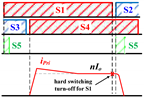 | 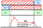 |  | 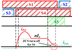 |
| Resonant tank | = 100 kHz; = 3.6 µH; = 10 µF | = 50 kHz; = 10 µH; = 47 nF | = 100 kHz; = 4.1 µH; = 10 µF | = 30 kHz; = 20 µH; = 112 nF |
| Voltage stress across the rectifier | ||||
| : switching frequency;: leakage inductor of transformer; : clamp capacitor; : primary current; : load current; n: secondary/primary transformer ratio; : source voltage | ||||
| Parameter | Designator | Value |
|---|---|---|
| Input voltage nominal | 380 V | |
| Output voltage range | 250–420 V | |
| Maximum output power | 3.5 kW | |
| Switching frequency | 30 kHz | |
| Resonant frequency | 100 kHz |
| Parameter (Designator) | Measured Value |
|---|---|
| Turn ratio of the transformer (n1:n2) | 11:13 |
| Magnetizing inductance () | 828 µH |
| Leakage inductance () | 20 µH |
| Clamp capacitor () | 112 nF |
| Filter output inductor () | 360 µH |
| Component | Manufacturer | Part # |
|---|---|---|
| Primary-side switch ( | Infineon | IPW60R041C6 |
| Active-clamp switch () | Fairchild | FCH76N60N |
| Rectifier diodes ( | Vishay | HFA50PA60 |
© 2018 by the authors. Licensee MDPI, Basel, Switzerland. This article is an open access article distributed under the terms and conditions of the Creative Commons Attribution (CC BY) license (http://creativecommons.org/licenses/by/4.0/).
Share and Cite
Tran, D.; Vu, N.; Choi, W. A Quasi-Resonant ZVZCS Phase-Shifted Full-Bridge Converter with an Active Clamp in the Secondary Side. Energies 2018, 11, 2868. https://doi.org/10.3390/en11112868
Tran D, Vu N, Choi W. A Quasi-Resonant ZVZCS Phase-Shifted Full-Bridge Converter with an Active Clamp in the Secondary Side. Energies. 2018; 11(11):2868. https://doi.org/10.3390/en11112868
Chicago/Turabian StyleTran, Duong, Nam Vu, and Woojin Choi. 2018. "A Quasi-Resonant ZVZCS Phase-Shifted Full-Bridge Converter with an Active Clamp in the Secondary Side" Energies 11, no. 11: 2868. https://doi.org/10.3390/en11112868
APA StyleTran, D., Vu, N., & Choi, W. (2018). A Quasi-Resonant ZVZCS Phase-Shifted Full-Bridge Converter with an Active Clamp in the Secondary Side. Energies, 11(11), 2868. https://doi.org/10.3390/en11112868