Article

Islanding Detection of Synchronous Distributed Generator Based on the Active and Reactive Power Control Loops

by
Reza Zamani
1,
Mohamad-Esmail Hamedani-Golshan
1,
Hassan Haes Alhelou
1,2,
Pierluigi Siano
3,* and
Hemanshu R. Pota
4
1
Department of Electrical and Computer Engineering, Isfahan University of Technology, Isfahan 84156-83111, Iran
2
Department of Electrical Power Engineering, Faculty of Mechanical and Electrical Engineering, Tishreen University, 2230 Lattakia, Syria
3
Department of Management & Innovation Systems, University of Salerno, 84084 Salerno, Italy
4
School of Engineering and Information Technology, The University of New South Wales, Canberra 2610, Australia
*
Author to whom correspondence should be addressed.
Energies 2018, 11(10), 2819; https://doi.org/10.3390/en11102819
Submission received: 4 October 2018 / Revised: 15 October 2018 / Accepted: 16 October 2018 / Published: 19 October 2018
(This article belongs to the Section F: Electrical Engineering)

Abstract

:
There has been a considerable importance for the islanding detection due to the growing integration of distributed generations (DGs) in the modern power grids. This paper proposes a novel active islanding detection scheme for synchronous DGs, considering two additional compensators and a positive feedback for each of active and reactive power control loops. The added blocks are designed using the small gain theorem and stability margins definition considering characteristics of open loop transfer functions of synchronous DG control loops. Islanding can be detected using the proposed method even where there is an exact match between generation and local load without sacrificing power quality. In addition, the performance of the proposed method can be retained even with high penetration of motor loads. The proposed scheme improves the stability and power quality of the grid, when the synchronous DG is subjected to the grid-connected disturbances. Furthermore, this method augments the stability margins of the system in the grid-connected conditions to enhance the disturbances ride-through capability of the system and reduce the negative impact of the active methods on the power quality. Simultaneous advantages of the proposed scheme are demonstrated by modeling a test system in MATLAB software and time-domain simulation achieved by PSCAD.

1. Introduction

Integration of distributed generation (DG) into the power grids have an essential role to reduce transmission and distribution network capacity, improve the security of system, and reduce overall costs [1,2,3]. In the situation of intentional or unexpected loss of the main grid, DG units continue to energize the islanded power system. Island operation of DGs may lead personal safety issues and severe electrical hazard to equipments due to out-of-phase re-closure. Hence, DG units should be disconnected in islanding situation as soon as possible and before auto-reclosing operation. Sometimes, DGs should be able to operate in islanding situation according to some grid codes [4] and standards [5]. Hence, the islanding should be detected in proper time in order to switch the DG control scheme to perform the autonomous islanded operation.
Islanding detection techniques can be classified into active and passive methods in terms of their interaction with the system. When a portion of the system consists of a DG and local loads isolate from the main grid, the frequency and voltage of the islanded system will deviate from their nominal values. The frequency, rate of change of frequency (ROCOF), and voltage relays [6,7,8] are the simplest and most common ways to detect the islanding. These passive methods can detect the islanding by using monitoring the electrical quantities and without any interaction with the system. In reference [9], a passive islanding detection method is proposed based on recognition of the output voltage signal pattern of DG. The pattern illustrates dynamic behavior of the DG in islanding and non-islanding situation. Some other passive islanding detection solutions are [10,11,12,13,14], and vector surge relay [15]. The main drawbacks of these methods are large none-detection zone (NDZ), low ability discrimination between islanding and non-islanding situation, and the problem of determining the threshold values.
Active islanding detection methods directly interact with the system to minimize or even eliminate the NDZ. These methods use the control loops related to each DG. In literature, the most active schemes have been proposed for inverter-based DG. In reference [16] a specific current harmonic is injected intentionally to the system which can be measured in islanding situation. Some of active methods which have been implemented for inverter-based generators include active frequency drift (AFD) [17,18,19,20,21], Sandia voltage/frequency shift (SVS and SFS) [22], and slip-mode frequency shift [23]. The active methods have high probability of interference with other devices and non-linear loads. In addition, the main disadvantage of these techniques is degradation of power quality.
Active islanding detection for the synchronous DGs is based on modifying active and reactive power control loops of the synchronous DG. These modifications are designed to cause the instability of the system in the islanding situation without any adverse impact on the system operation when the DG is connected to the main grid. When the system is unstable, the electrical quantities of the system such as frequency and voltage deviate from their nominal values. Hence, the islanding can be detected as soon as this instability trigger the conventional relays. In reference [24], an active anti-islanding scheme based on a strong theory presented for synchronous DG which insert positive feedback for active and reactive power control loops to ensure that the system is intentionally unstable in the islanding situation. However, the scheme affects on the droop controllers operation and the ability of the DG to support the main grid during a low-voltage event in the grid, especially by applying the positive feedback for reactive power control loop. Other interesting approach is modifying and inserting specific controllers into active and reactive power control loops [25] by adding the integral controller to the synchronous DG conventional control loop scheme. This method needs communication links. In addition, its performance in islanding detection can be affected when the loads have inertia. The above literature survey shows that there is a research gaps in the field of designing a suitable active islanding detection schemes for synchronous DGs that need to be addressed.
This paper proposes a novel active and reactive power control scheme for synchronous DG including positive feedback and additional suitable compensators. The important features of the proposed scheme include selecting appropriate location and inputs for added blocks to the synchronous DG control loops, and designing procedure of these blocks to attain most appropriate characteristics of the islanding detection and support of the main grid during non-islanding disturbances by synchronous DG. Islanding can be detected with negligible NDZ by this approach even when the penetration of motor load is high in the grid. The proposed scheme has no adverse effect on power quality and normal operation of synchronous DG. Also, the effective performance of the droop controllers is retained by using the proposed scheme. In addition, the proposed scheme enhance the disturbance ride-through capability of the system under grid-connected disturbances. Thus, the proposed scheme realize both islanding detection ability and ride-through capability enhancement for synchronous DG, simultaneously, without sacrificing the islanding detection functionality. Although the proposed scheme is based on a depth theory and considerable design steps, its implementation is easily achieved by a digital controller.
This paper is organized as follows: The dynamic model of the system components are explained in Section 2. Section 3 and Section 4 presents the proposed active islanding detection scheme. In Section 5, simulation results are investigated to validate the performance of the proposed method. The conclusions are drawn in the last section.

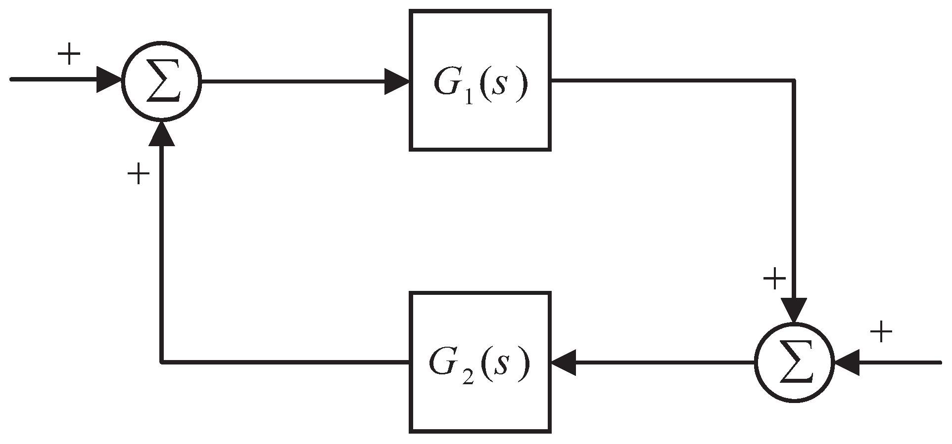
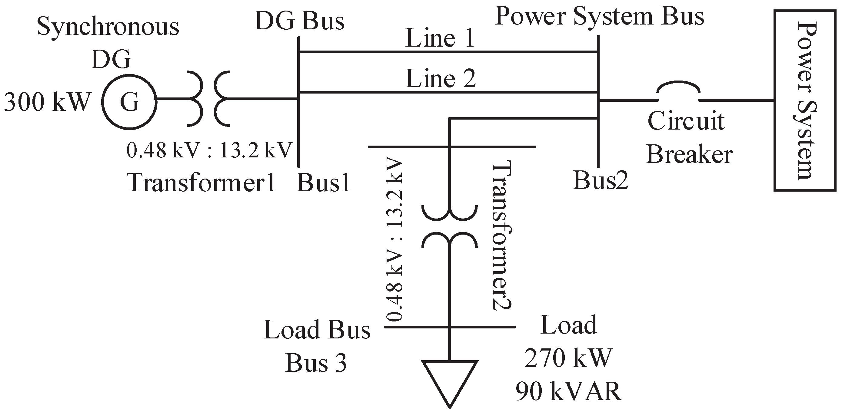
2. System Dynamic Model

Active anti-islanding scheme depends on the dynamic system devices including synchronous DG and active and reactive power control loops. The frequency and the voltage of the system is determined by the main grid when the DG is connected to the utility network. Whereas, the frequency and the voltage will be determined according to dynamic characteristics of the local load, synchronous generator, and its control loops when the DG is isolated from the main grid.
The simplified model of synchronous machine shown in Figure 1 is used to design procedure of active islanding detection purpose. However, the performance of the procedure should be investigated by the detail model.
The active power control loop of a synchronous generator consists of the prime mover and the governor system. The governor was modeled with a droop controller. Also, a droop control method is introduced in references [26,27,28,29]. The active power control loop determines the output active power of the generator according to the reference value. It also contributes to the primary frequency control. The frequency of the DG can be regulated by changing the gate position of the prime mover by means of the governor system which can be represented as a droop characteristic.
The direct current of the synchronous generator field is supplied by the reactive control loop. In addition, this control system should contributes to stability and voltage control of the power system. The reactive power control loop consists of reactive power regulator, automatic voltage regulator (AVR), and filed response controller which can be indicated by two proportional-integral (PI) and a first-order controller, respectively.
In general, the load models can be classified into static and dynamic models. Active and reactive powers of the static loads are algebraic functions of the load bus voltage and frequency. The static loads have a fast response to voltage and frequency changes. Whereas, the response of dynamic loads to the changes are mostly slow and their active and reactive powers are differential functions of the voltage and frequency of the load bus. The loads type has a considerable influence on timely islanding detection. Therefore, in the control block diagram (as shown in Figure 1), the transfer function of the static loads is a constant gain but the transfer function of the dynamic loads is function of the s (Laplace operator). The resistor-inductor-capacitor (RLC) and induction motor loads are selected in this study as a common representative of the static and dynamic loads, respectively.

3. Proposed Active Islanding Method

The active anti-islanding methods for synchronous DG are based on a direct interaction between the active/reactive power control loops of the synchronous generator and the system. In this mechanism, the terminal voltage or/and frequency of the synchronous DG deviate dramatically from their nominal values and hence violate the preset thresholds of the conventional voltage or/and frequency relays, respectively. This paper proposes an active islanding detection scheme for synchronous DG, based on modified active and reactive power control loops. Figure 2 shows the proposed islanding detection scheme. The proposed scheme for active power control loop consists of active power positive feedback (APF) block as a positive feedback and compensators 1, 2. The APF takes the active power of the synchronous DG as input and inserts an additional signal to the active power control loop at point 1. Similarly, the reactive power control loop is formed of compensator 1, 2 and the reactive power positive feedback (RPF) which takes the reactive power of synchronous DG as input and inserts a disturbance to reactive power control loop. In the proposed method, islanding can be detected by amplify the dynamic response of the synchronous DG in islanding situation.
The main observations on which the proposed scheme is based are: (1) The power system oscillations are more pronounced for generator active/reactive power output following a disturbance in the grid. Hence, generator active and reactive powers are selected as the inputs of APF and RPF to better sense of the oscillations. (2) Structure of the feedback system should be properly designed to reduce negative effects on normal operation of the synchronous DG. The proposed scheme should also retain the desired performance of the droop characteristics by selecting suitable location and input for APF and RPF in the active and reactive power control loop, respectively. (3) The stability margins of the active and reactive control loops should be increased in the proposed scheme which leads to the disturbance ride-through capability enhancement of the system. Hence, the support ability of the synchronous DG to the main grid can be significantly improved during grid-connected disturbances.
The first step of the design procedure of the proposed scheme is to determine the APF and RPF characteristics that leads to instability of the system in islanding situation and to keep stable operation in grid-connected conditions. The APF and RPF stability requirements for design objectives in islanding and grid-connected situation can be derived from small gain theorem. The small gain theorem gives sufficient conditions for stability of a feedback control system. Consider a feedback system with transfer functions G 1 ( s ) and G 2 ( s ) as shown in Figure 3. The small gain theorem says if G 1 ( s ) and G 2 ( s ) are linear, time-invariant, and stable transfer function, then the closed-loop system is stable if and only if the -norm of G 1 ( s ) G 2 ( s ) is less than 1 (or 0 dB) [30]. It means
G 1 ( s ) G 2 ( s ) < 1
where
G 1 ( s ) G 2 ( s ) = sup ω R G 1 ( s ) G 2 ( s )
where sup ω R . is the supremum, and . is the -norm which is the maximum or peak value of the system loop gain. Therefore, the bounded input implies a bounded output if the system satisfies the small gain theorem in Equation (1).
As indicated in Figure 1, the synchronous DG has two distinct dynamic behaviors under the islanding situation and grid-connected conditions. Hence, the dynamic response of the system can be analyzed by two specific open loop transfer functions (OLTF). The APF and RPF are designed to make the control system unstable when the system is islanded. Furthermore, the stable operation of the system under grid-connected conditions should not be affected by these positive feedbacks. According to the small gain theorem, the system is stable if and only if
A P F · O L T F P g c < 1 , R P F · O L T F Q g c < 1
where O L T F P g c and O L T F Q g c are open loop transfer functions of the active and reactive power control loops in grid-connected conditions, respectively. The OLTF of active/reactive control loops are obtained by defining the point 1 as the open loop input and point 2 as the open loop output.
According to the gain margin definition, a system is internally unstable (when the gain margin is less than zero) if the -norm of OLTF be greater than 1 while its associated phase is lagging by more than 180 . In other hand, the active power loop is unstable in the islanding situation if
A P F · O L T F P i s l > 1
and
O L T F P i s l ( 1 + A P F · O L T F P i s l ) ω = ω 0 = π
Similarly for the reactive power control loop we have
R P F · O L T F Q i s l > 1
and
O L T F Q i s l ( 1 + R P F · O L T F Q i s l ) ω = ω 0 = π
where ω 0 is the gain crossover frequency, that means, the associated frequency when the -norm of the system is crossed from 1 (0 dB). According to this process, the APF and RPF are designed to meet the stable operation in grid-connected conditions and islanding situation unstable requirements, simultaneously.
After determining the appropriate APF and RPF positive feedbacks, the compensators 1, 2 are designed to achieve the desired values of stability margins in islanding and grid-connected situation. For this purpose, the compensators transfer function (CTF) are defined as follow
C T F = k 1 z s + 1 1 p s + 1
where k, z, and p are the gain, zero, and pole of the transfer function of each compensator, respectively. If desired values of the gain margin G M and the phase margin P M are considered respectively, for the active/reactive power control loop in islanding situation, the characteristic of the compensators can be calculated as
ω c = z p
P M = sin 1 α 1 α + 1 , α = p z
G M = C T F ω = ω c
Here ω c is the cut-off frequency of the active/reactive power control loop without considering the compensator. By designing the compensators which lead to a non-minimum phase system, instability of the system in islanding situation can be slightly increased without compromising stable operation of grid-connected conditions.

4. Design of the Proposed Scheme for the Test System

Figure 4 shows a simple distribution system with the model data given in Appendix. In this system, a synchronous DG is connected to the main grid through a feeder and the islanding would occur if the circuit breaker opened.

4.1. Design Procedure

To guarantee the performance of the proposed scheme, the design of APF and RPF have been done in the worst-case scenario by considering motor load model and when the load and generation are closely matched. Figure 5 shows the OLTF of the active power control loop in grid-connected conditions for this test system and without APF and compensators. The APF characteristic is derived from the small gain theorem and to satisfy the aforementioned equations in the design section. The APF can be represented by a second-order transfer function with a pair of complex conjugate poles as shown in Figure 5. A second-order transfer function is considered to reshape the peak value of the OLTF for active/reactive control loop to locate below the 0 dB in islanding situation and above the 0 dB in the grid-connected conditions. Hence, according to the previous section, the system retain stable in grid-connected conditions and is unstable in the islanding situation.
Adding a third pole to this function which is located far away from other poles, increase the overshot of the system response and instability in case of islanding situation which the system is unstable [31]. However, the stability of the stable system when the DG is connected to the main grid is not affected significantly by the third pole if it located far away from other poles. Based on above arguments, design of the APF and RPF for the system shown in Figure 4 are as
A P F = 5 s 2 ( s + 100.646 ) s 2 + 0.054 s + 0.001
R P F = 20 s 2 ( s + 150.188 ) s 2 + 0.612 s + 0.0036
Designing the compensators 1, 2 for active/reactive power control loops led to specific stability margins. The results in Table 1 show the gain and phase margin of active and reactive control loops in islanding situation for different values of the compensators time constants. Four different load conditions are considered in this table as: (1) no-load, (2) resistive 1 p.u. load, (3) 1 p.u. motor load, (4) 1 p.u. motor load and 1 p.u. resistive load. The calculated gain and phase margins are negative and indicate the system instability that leads to fast detection of islanding situation. As shown in this table, the system is clearly unstable in islanding situation with high negative stability margins even with the presence of of motor load and when the generation and load are closely matched.

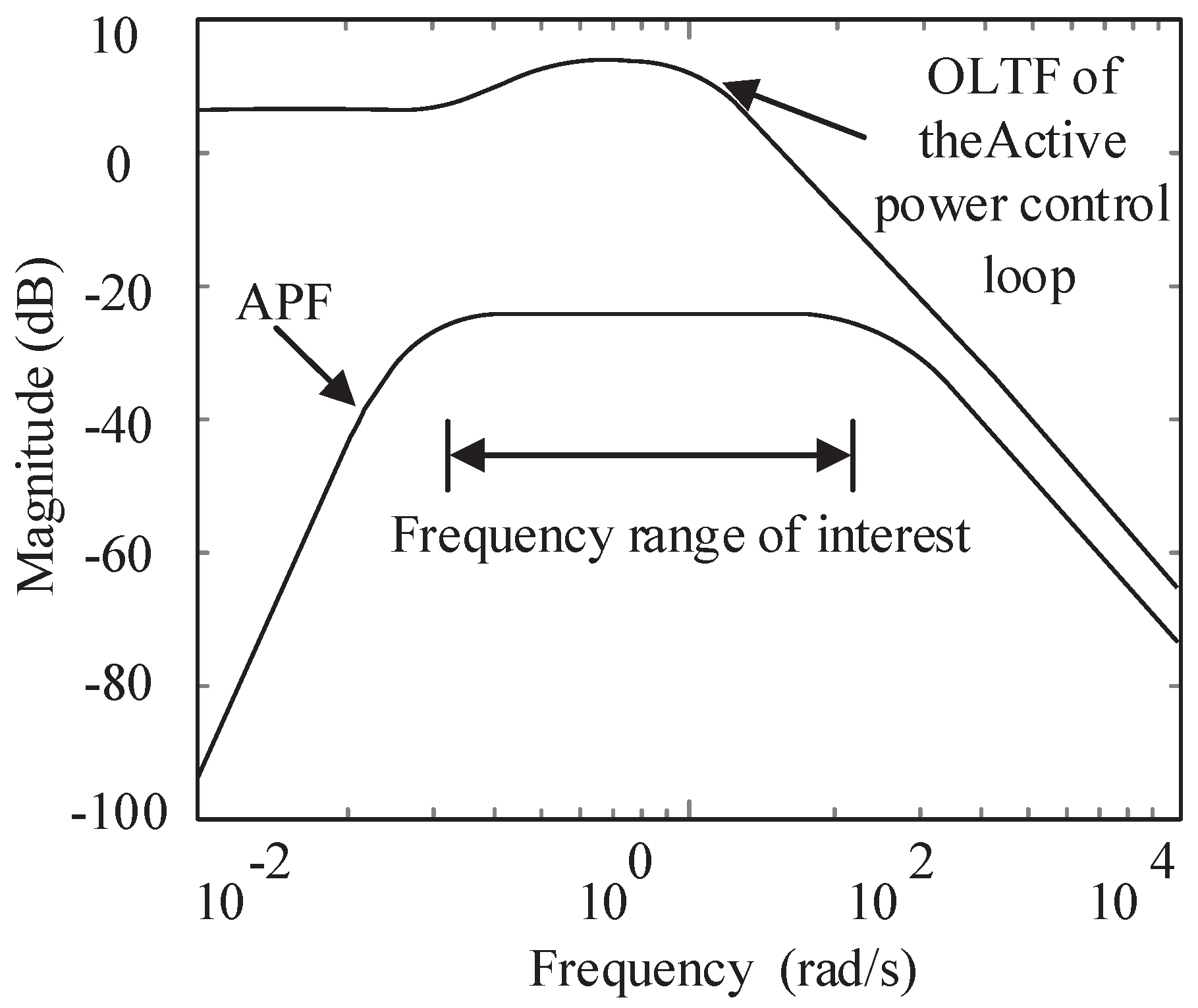
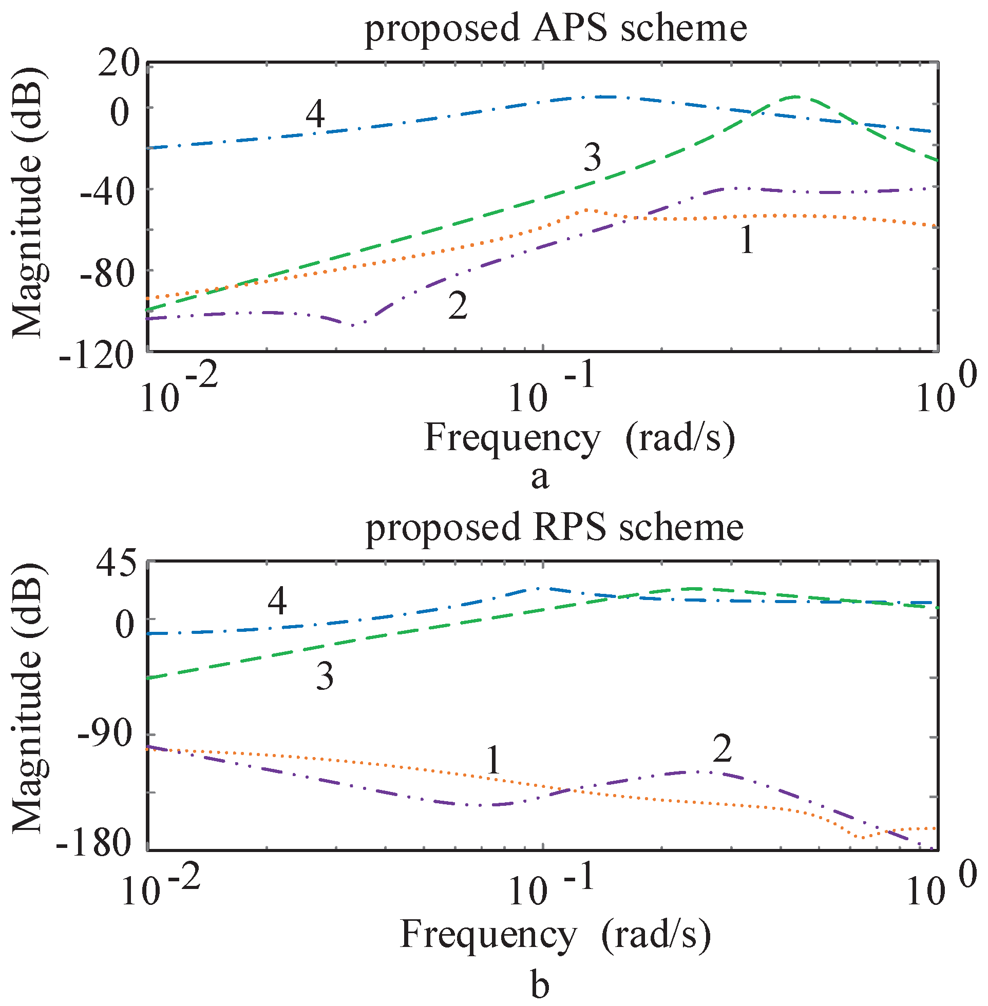
4.2. Frequency Domain Analysis

The test system is modeled in MATLAB Simulink software for the frequency domain analysis. It should be noticed that the cross-coupling between active and reactive power control loops is considered in this study. Figure 6 shows the open loop gain of active and reactive control loops in the case of the proposed scheme and the case of conventional control loop. Δ P indicates the power imbalance between local load and synchronous generation. The performance of the proposed method can be assessed in islanding and non-islanding situations.

4.2.1. Islanding Situation

The peak values of both active/reactive power control loop gain in conventional scheme are less than 0 dB in grid-connected mode and even in the islanding situation. Hence, the synchronous DG remains stable when it disconnects from the main grid, thus the islanding situation will not be easily detected. On the other hand, the proposed scheme increase both active and reactive power control loops gain in the islanding situation. Specifically, the loop gains in islanding situation using the proposed scheme are above 0 dB which lead to instability of the islanded power system. However, the proposed scheme does not disrupt the normal operation of the system under the grid-connected conditions since the active/reactive power control loop gains are less than 0 dB which lead to stable behavior of the system. Motor loads as a considerable part of system load, have usually significant influence on dynamic characteristic of distribution systems. Islanding detection with high penetration of motor loads are still challenging due to their dynamic response. The effect of motor load has been investigated on the proposed scheme when an induction motor load is considered instead of the static load in Figure 4. As a result, the active/reactive power control loop gain decrease in comparison with RLC load as shown in Figure 7. Nevertheless, the performance of the proposed scheme is retained successful with presence of the motor load. In addition, as shown in Figure 7, the reactive power control loop is more effective than the active power control loop under this condition. Therefore, islanding can be well detected using the proposed scheme for RLC as well as motor loads. Furthermore, effect of motor inertia has been represented in Figure 7. The active/reactive power control loop gain are diminished with the increase in the inertia. Thus, the islanding detection scheme can fail when the motor inertia is considerably greater than the synchronous DG inertia.

4.2.2. Grid-Connected Conditions

The margins between peak values of the open loop gains and 0 dB indicate the stability characteristic of the system. As the peak value of the open loop gain be close to 0 dB, the probability of the degrading system stability increases in grid-connected conditions which reduces reliability and security of the system. As aforementioned, sustainable operation of the DG is required when the main grid is subjected to transient disturbances in order to contribute to the main grid frequency and voltage support ability. The ride-through capability of the synchronous DG is enhanced with increasing stability margins in the proposed method as shown in Figure 6. From the open loop gains shown in Figure 6a, it can be seen that the margins between the peak value of active power open loop gain and 0 dB is around −70 dB and −30 dB in grid-connected conditions in the case of the proposed scheme and the conventional control, respectively. In the same way, the margins are around −110 dB and −60 dB using the proposed method and the conventional one for reactive power control loop, respectively. Therefore, the stability of the synchronous DG is increased using proposed scheme in order to support the main grid more effectively. This fact can be seen with time-domain simulation results that shows the ride-through capability enhancement of the synchronous DG.

5. Simulation Results and Discussion

The proposed islanding detection scheme is evaluated using the time-domain simulation of the test system depicted in Figure 4 which is modeled in PSCAD software. In the time-domain simulation, the sampling time of 830 μ s is used and the synchronous DG output frequency is measured through a phase-lock loop (PLL) block. These simulations consist of islanding and non-islanding conditions such as three-phase short circuit fault and load shedding.

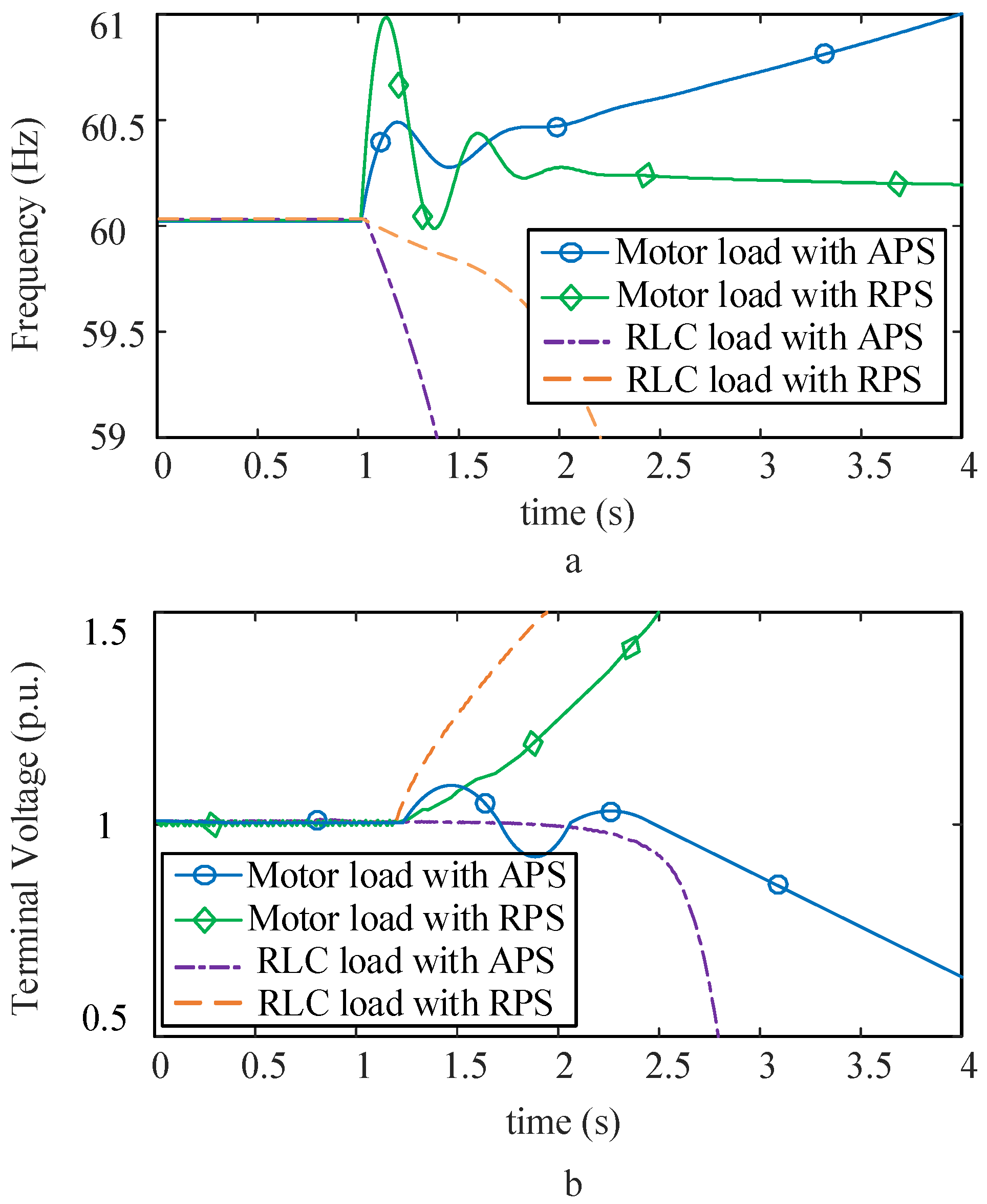
5.1. Islanding Situation

Islanding situation occurs by opening the circuit breaker at t = 1.0 s, assuming the generation and load are closely matched before the islanding. Figure 8 shows the performance of the proposed scheme for both static load and induction motor load. The changes and deviations of frequency and terminal voltage magnitude without using the proposed active scheme are too small in case of islanding, due to the closely balance between generation and load. Hence, the islanded power system continue to its normal operation. Figure 8 shows abrupt changes in frequency and terminal voltage magnitude with considering RLC load and using APF or RPF scheme. It can be seen that, both frequency and voltage can be deviate from their initial values for both RLC load and induction motor load in less than 2 s when the APF or RPF is used. However, the variation of frequency is more severe than the terminal voltage variation using the APF. Similarly, these variations are more significant for voltage magnitude if the RPF is applied. In general, islanding can be detected less than 1 s using combination of proposed scheme for both RLC load and motor load. These results are consistent with the frequency domain analysis.

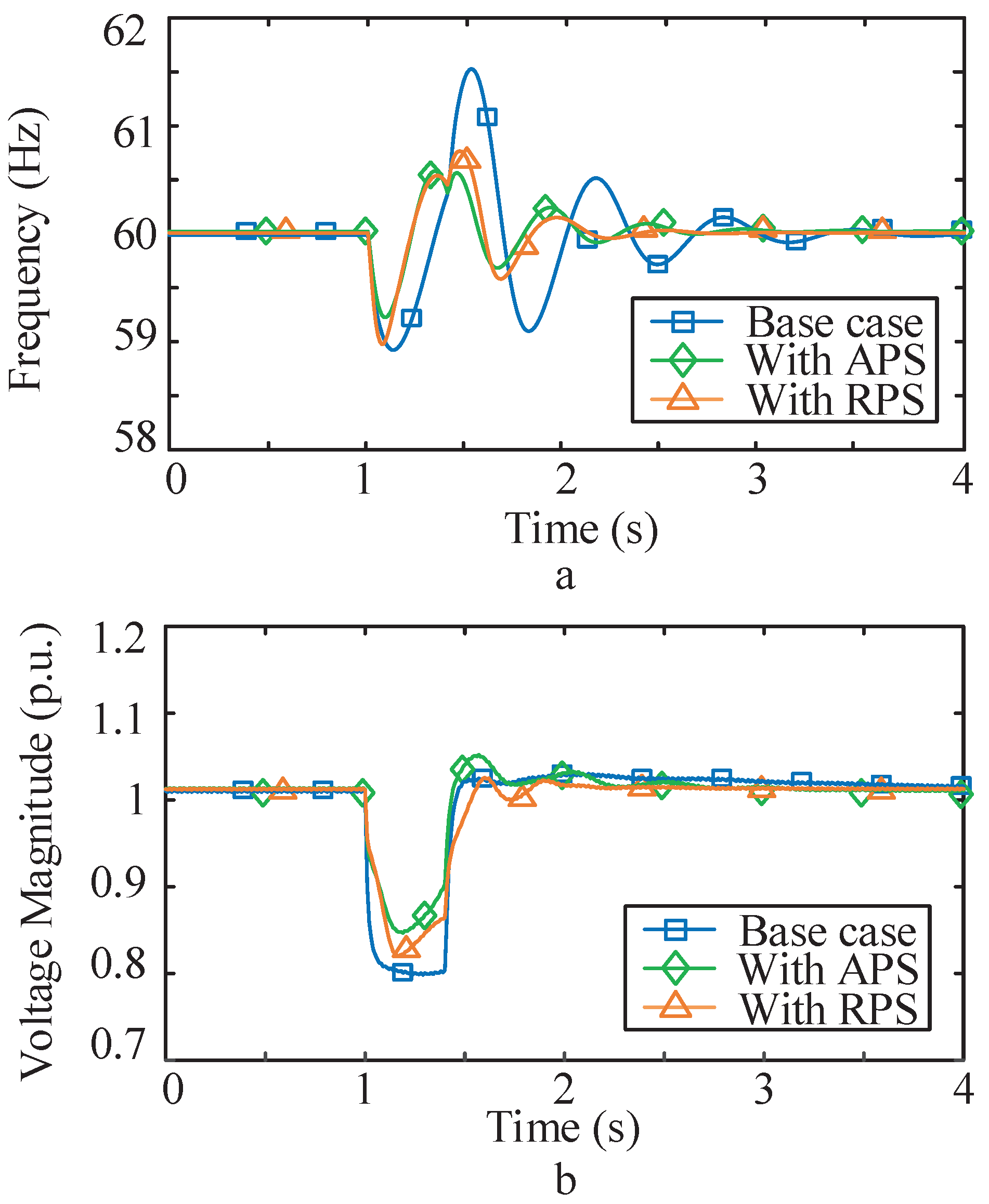
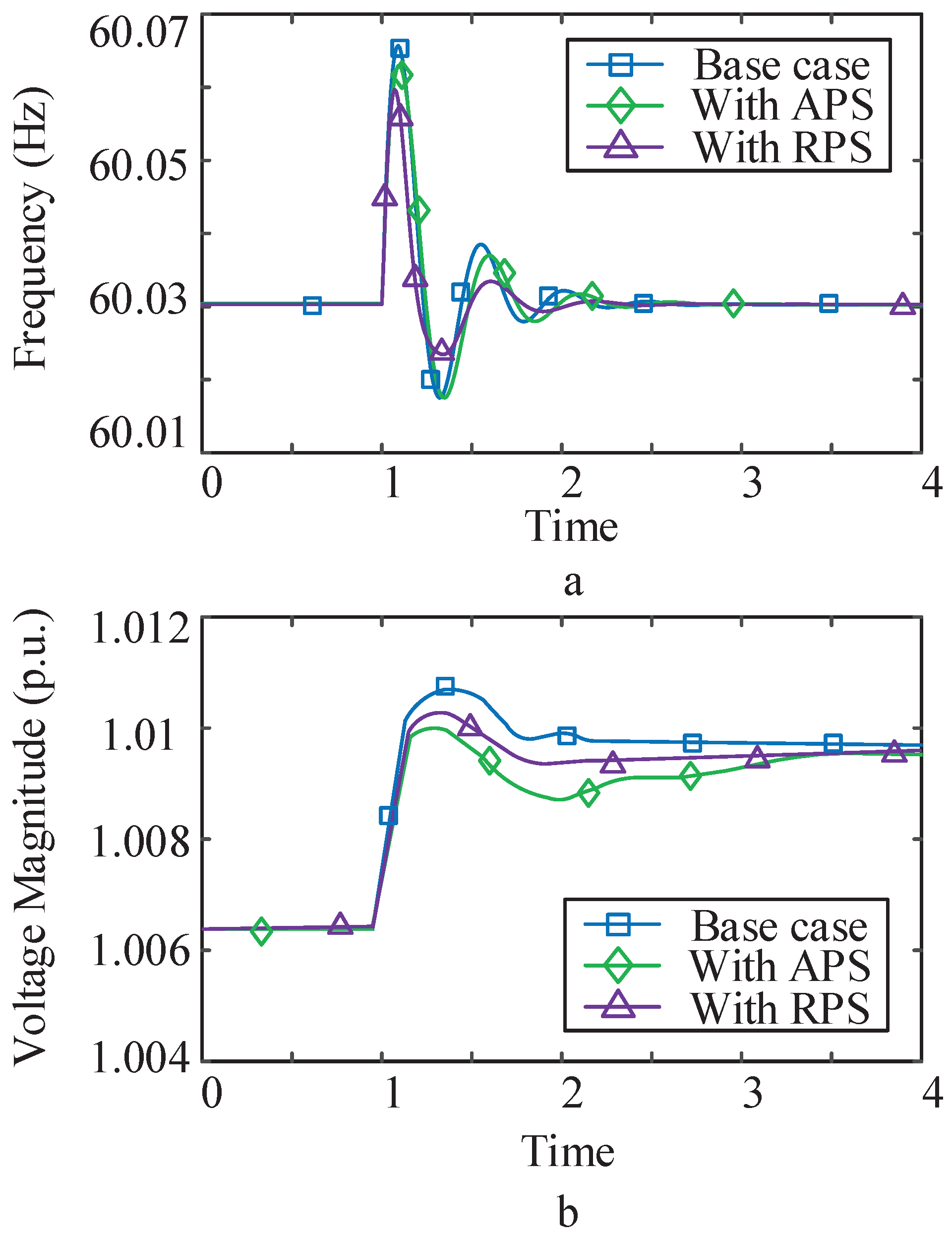
5.2. Grid-Connected Conditions

The performance of the proposed islanding detection scheme are also investigated under non-islanding disturbances. The islanding should be discriminated from grid-connected disturbances and the detection methods should not operate under non-islanding events for two main reason. Firstly, the revenues of DGs can be curtailed with wrong disconnect of DG units. Secondly, support of DGs from the main grid is required when the power system is subjected to a disturbance. Typical non-islanding disturbances are short circuit faults, connecting/disconnecting of loads, and capacitor bank switching. The relays based on the passive islanding detection methods can have serious issues under these circumstances to properly distinguish between islanding and grid-connected situations. In addition, it should be noticed that, the main drawback of the active islanding detection methods is negative impact on the power quality of the system which is improved in this paper. The proposed scheme is assessed for the three-phase fault and load reduction, as representatives of the grid disturbances. The response of the synchronous DG is evaluated when a three-phase fault occurred on line 2 near to the power system bus (Bus 2) at t = 1.0 s. This fault is temporary and cleared after 0.4 s. Figure 9 shows the performance of the proposed scheme in comparison with the base case (without proposed scheme). It can be observed that, changes of the frequency and terminal voltage are both diminished by using the proposed scheme. It means that, the synchronous DG becomes more stable and contributes to supporting the frequency and voltage of main grid. Figure 9a shows that response of frequency is settled down more quickly after clearing the fault and it reaches to the steady state in a short time. Load connecting and disconnecting are typical disturbance that occurs frequently in a distribution system. Figure 10 shows the frequency and terminal voltage of the synchronous DG when 10 % of the local load disconnects at t = 1.0 s. It can be seen that the proposed scheme enhance the ride-through capability of the synchronous DG when it subjected to a voltage swell event. Therefore, the proposed scheme enhances the stability of the system which leads to decrease in the frequency and voltage changes that improves the power quality issue of the system under non-islanding conditions.

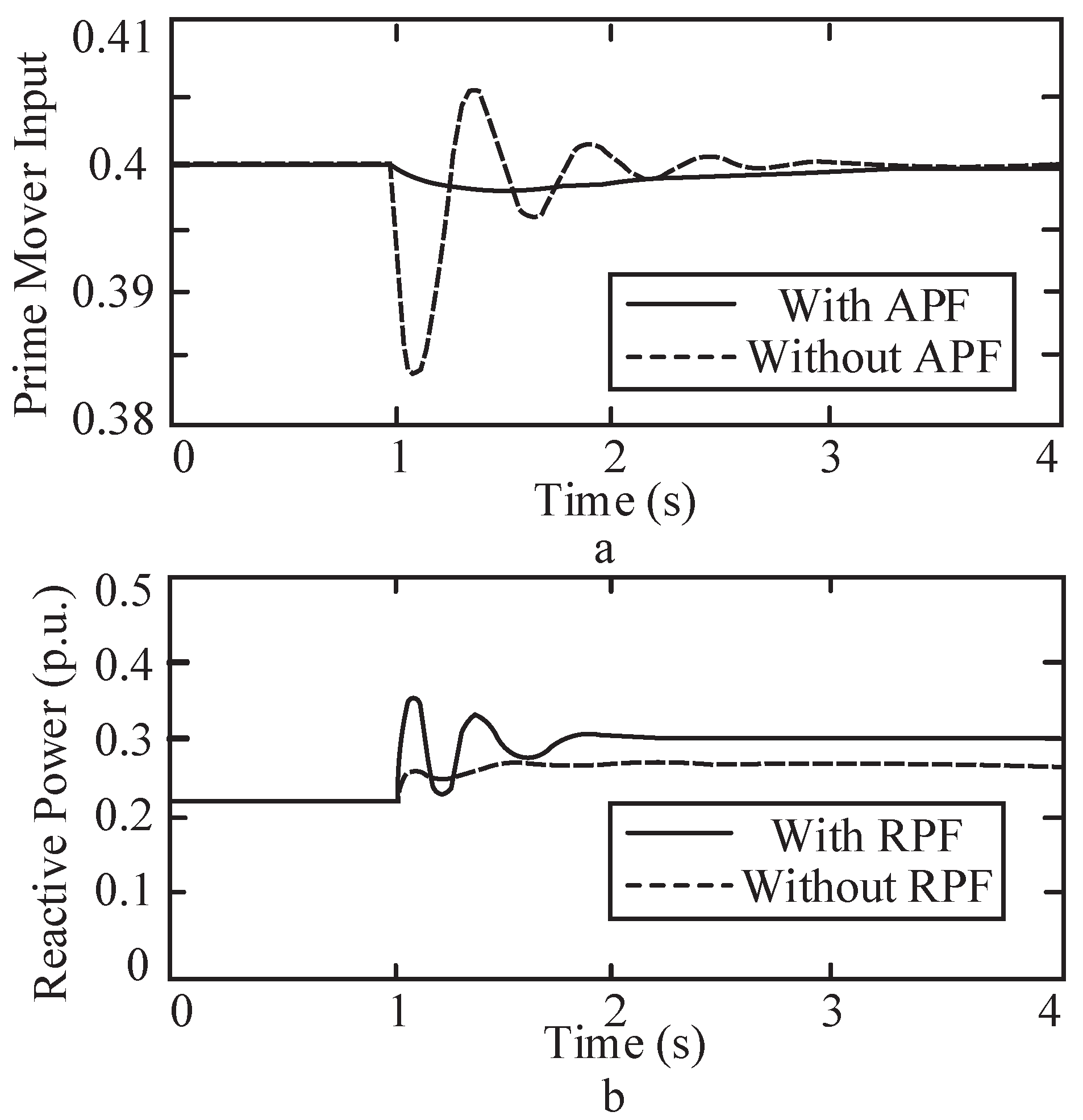
5.3. Ride-Through Capability Enhancement

Increasing the stability margins of the system in the grid-connected conditions helps that the changes in voltage and frequency of the system be more suppressed. Hence, the synchronous DG can continue to support the main grid even during severe disturbances without losing its stability. Obviously, there is a direct trade-off between ride-through capability and severity of instability in islanding situation. As discussed before, the system has two distinct dynamic responses and consequently two specific control systems. The proposed positive feedbacks for active and reactive control loops provide sufficient negative stability margins in islanding situation which is required for reliable and timely detection. Hence, the compensators 1, 2 can be designed to increase the stability of the system in grid-connected conditions without significant effect on the detection time of the islanding situation. Figure 11 shows the enhancement of ride-through capability using the proposed method, when one of the two parallel lines connecting the DG bus to the main grid, is disconnected due to protection operation at time t = 1 s. As shown in Figure 11a the input signal of the prime mover has been diminished significantly using the proposed scheme for active power control loop which results in increasing the life time of governor. Figure 12 shows the frequency and voltage of the synchronous DG during the loss of one of the parallel lines. Hence, the frequency and voltage responses will be improved during the loss of one of the parallel lines. Furthermore, since the impedance of the system is increased by the outage of the faulty line, a voltage dip at the point of common coupling (PCC) occurs. Hence, reactive power of synchronous DG has been increased using the proposed scheme to support the main grid during this disturbance effectively.

6. Conclusions

This paper proposes an active islanding detection scheme for active power and reactive power control loops of the synchronous DG. Timely detection of islanding situation is guaranteed using the proposed scheme for both static load and motor load even with an exact match between generation and load demand. Islanding and non-islanding disturbances can be well discriminated by the novel proposed scheme. The APF and RPF which used in the control loops, have more effects on frequency and voltage variation, respectively. Thus, simultaneous using of APF and RPF has a distinguished performance to detect islanding situation in less than 1 second even with high penetration of motor load. Time-domain simulations and frequency domain analysis have been performed to elucidate the novel features of the proposed scheme in different scenarios. Another breakthrough of the proposed scheme is enhancement of disturbance ride-through capability of the system. It means that the synchronous DG will be more stable and contribute more effectively to voltage and frequency support when main grid is subjected to a disturbance without compromising islanding detection ability. Oscillation of frequency is damped much faster and voltage magnitude is suppressed effectively using the proposed scheme under non-islanding events such as low-voltage events. The proposed scheme has a strong theoretical bases from one side, and it is a practical and applicable scheme from other side because it can be easily implemented by a digital controller. As future works, the concept of the proposed method can be further developed for other types of DGs such as virtual synchronous generator which behave like a synchronous generator during short time intervals. Likewise, the proposed method in this paper can be modified for DGs connected to the main grid by power electronic devices such as renewable DGs.

Author Contributions

All authors worked on this manuscript together. All authors read and approved the final manuscript.

Funding

This research received no external funding.

Conflicts of Interest

The authors declare no conflict of interest.

References

  1. Jenkins, N.; Ekanayake, J.; Strbac, G. Distributed Generation; Institution of Engineering and Technology: London, UK, 2010; ISBN 9780863419584. [Google Scholar]
  2. Alhelou, H.H.; Golshan, M.H.; Askari-Marnani, J. Robust sensor fault detection and isolation scheme for interconnected smart power systems in presence of RER and EVs using unknown input observer. Int. J. Electr. Power Energy Syst. 2018, 99, 682–694. [Google Scholar] [CrossRef]
  3. Alhelou, H.S.H.; Golshan, M.; Fini, M.H. Multi agent electric vehicle control based primary frequency support for future smart micro-grid. In Proceedings of the Smart Grid Conference (SGC), Tehran, Iran, 22–23 December 2015; pp. 22–27. [Google Scholar]
  4. Network Code for Requirements for Grid Connection Applicable to all Generators. Available online: https://www.google.com/search?q=19048-Requirements+for+Generators+Presentation.pdf&ie=utf-8&oe=utf-8 (accessed on 3 October 2018).
  5. Photovoltaics, D.G.; Storage, E. IEEE Guide for Conducting Distribution Impact Studies for Distributed Resource Interconnection. IEEE 2014. [Google Scholar] [CrossRef]
  6. Eshraghi, A.; Ghorbani, R. Islanding detection and over voltage mitigation using controllable loads. Sustain. Energy Grids Netw. 2016, 6, 125–135. [Google Scholar] [CrossRef]
  7. Gupta, P.; Bhatia, R.; Jain, D. Active ROCOF relay for islanding detection. IEEE Trans. Power Deliv. 2017, 32, 420–429. [Google Scholar] [CrossRef]
  8. Faqhruldin, O.N.; El-Saadany, E.F.; Zeineldin, H.H. A universal islanding detection technique for distributed generation using pattern recognition. IEEE Trans. Smart Grid 2014, 5, 1985–1992. [Google Scholar] [CrossRef]
  9. Zamani, R.; Golshan, M.E.H. Islanding detection of synchronous machine-based distributed generators using signal trajectory pattern recognition. In Proceedings of the IEEE 2018 6th International Istanbul Smart Grids and Cities Congress and Fair (ICSG), Istanbul, Turkey, 25–26 April 2018; pp. 91–95. [Google Scholar]
  10. Alshareef, S.; Talwar, S.; Morsi, W.G. A new approach based on wavelet design and machine learning for islanding detection of distributed generation. IEEE Trans. Smart Grid 2014, 5, 1575–1583. [Google Scholar] [CrossRef]
  11. Xing, J.; Mu, L. A New Passive Islanding Detection Solution Based on Accumulated Phase Angle Drift. Appl. Sci. 2018, 8, 1340. [Google Scholar] [CrossRef]
  12. Padhee, M.; Dash, P.K.; Krishnanand, K.; Rout, P.K. A fast Gauss-Newton algorithm for islanding detection in distributed generation. IEEE Trans. Smart Grid 2012, 3, 1181–1191. [Google Scholar] [CrossRef]
  13. Khamis, A.; Xu, Y.; Dong, Z.Y.; Zhang, R. Faster Detection of Microgrid Islanding Events using an Adaptive Ensemble Classifier. IEEE Trans. Smart Grid 2016, 9, 1889–1899. [Google Scholar] [CrossRef]
  14. Cui, Q.; El-Arroudi, K.; Joos, G. Islanding Detection of Hybrid Distributed Generation under Reduced Non-detection Zone. IEEE Trans. Smart Grid 2017, 9, 5027–5037. [Google Scholar] [CrossRef]
  15. Alam, M.R.; Muttaqi, K.M.; Bouzerdoum, A. A multifeature-based approach for islanding detection of DG in the subcritical region of vector surge relays. IEEE Trans. Power Deliv. 2014, 29, 2349–2358. [Google Scholar] [CrossRef]
  16. Voglitsis, D.; Papanikolaou, N.; Kyritsis, A.C. Incorporation of Harmonic Injection in an Interleaved Flyback Inverter for the Implementation of an Active Anti-Islanding Technique. IEEE Trans. Power Electron. 2017, 32, 8526–8543. [Google Scholar] [CrossRef]
  17. Liu, S.; Zhuang, S.; Xu, Q.; Xiao, J. Improved voltage shift islanding detection method for multi-inverter grid-connected photovoltaic systems. IET Gener. Trans. Distrib. 2016, 10, 3163–3169. [Google Scholar] [CrossRef]
  18. Wen, B.; Boroyevich, D.; Burgos, R.; Shen, Z.; Mattavelli, P. Impedance-based analysis of active frequency drift islanding detection for grid-tied inverter system. IEEE Trans. Ind. Appl. 2016, 52, 332–341. [Google Scholar] [CrossRef]
  19. Lopes, L.A.; Sun, H. Performance assessment of active frequency drifting islanding detection methods. IEEE Trans. Energy Conver. 2006, 21, 171–180. [Google Scholar] [CrossRef]
  20. Kwak, R.; Lee, J.H.; Lee, K.B. Active Frequency Drift Method for Islanding Detection Applied to Micro-inverter with Uncontrollable Reactive Power. J. Power Electron. 2016, 16, 1918–1927. [Google Scholar] [CrossRef] [Green Version]
  21. Yafaoui, A.; Wu, B.; Kouro, S. Improved active frequency drift anti-islanding detection method for grid connected photovoltaic systems. IEEE Trans. Power Electron. 2012, 27, 2367–2375. [Google Scholar] [CrossRef]
  22. Zeineldin, H.; Kennedy, S. Sandia frequency-shift parameter selection to eliminate nondetection zones. IEEE Trans. Power Deliv. 2009, 24, 486–487. [Google Scholar] [CrossRef]
  23. Liu, F.; Kang, Y.; Zhang, Y.; Duan, S.; Lin, X. Improved SMS islanding detection method for grid-connected converters. IET Renew. Power Gener. 2010, 4, 36–42. [Google Scholar] [CrossRef]
  24. Du, P.; Nelson, J.K.; Ye, Z. Active anti-islanding schemes for synchronous-machine-based distributed generators. IEE Proc.-Gener. Transm. Distrib. 2005, 152, 597–606. [Google Scholar] [CrossRef]
  25. Roscoe, A.J.; Burt, G.M.; Bright, C.G. Avoiding the non-detection zone of passive loss-of-mains (islanding) relays for synchronous generation by using low bandwidth control loops and controlled reactive power mismatches. IEEE Trans. Smart Grid 2014, 5, 602–611. [Google Scholar] [CrossRef] [Green Version]
  26. Alhelou, H.H.; Golshan, M. Hierarchical plug-in EV control based on primary frequency response in interconnected smart grid. In Proceedings of the 24th Iranian Conference on Electrical Engineering (ICEE), Shiraz, Iran, 10–12 May 2016; pp. 561–566. [Google Scholar]
  27. Mobarrez, M.; Ghanbari, N.; Bhattacharya, S. Control Hardware-in-the-Loop Demonstration of a Building-Scale DC Microgrid Utilizing Distributed Control Algorithm. In Proceedings of the IEEE PES General Meeting, Oregan, OR, USA, 5–9 August 2018. [Google Scholar]
  28. Alhelou, H.; Hamedani-Golshan, M.E.; Zamani, R.; Heydarian-Forushani, E.; Siano, P. Challenges and Opportunities of Load Frequency Control in Conventional, Modern and Future Smart Power Systems: A Comprehensive Review. Energies 2018, 11, 2497. [Google Scholar] [CrossRef]
  29. Fini, M.H.; Yousefi, G.R.; Alhelou, H.H. Comparative study on the performance of many-objective and single-objective optimisation algorithms in tuning load frequency controllers of multi-area power systems. IET Gener. Transm. Distrib. 2016, 10, 2915–2923. [Google Scholar] [CrossRef]
  30. Desoer, C.A.; Vidyasagar, M. Feedback Systems: Input-Output Properties; Society for Industrial and Applied Mathematics: Philadelphia, PA, USA, 1975. [Google Scholar]
  31. Dorf, R.C.; Bishop, R.H. Modern Control Systems; Pearson Education Limited: London, UK, 2011. [Google Scholar]
Figure 1. Control block diagram of active and reactive power control loop.
Energies 11 02819 g001
Figure 2. Proposed control loops for the synchronous DG.
Energies 11 02819 g002
Figure 3. A simplified feedback system.
Energies 11 02819 g003
Figure 4. Single-line diagram of the test system.
Energies 11 02819 g004
Figure 5. OLTF of active power control loop and APF characteristic.
Energies 11 02819 g005
Figure 6. Open loop gain of (a) active (b) reactive power control loop for different power imbalances; 1 Grid-connected Δ P = 0.5 % , 2 Grid-connected Δ P = 2.0 % , 3 Islanding Δ P = 0.5 % , 4 Islanding Δ P = 2.0 % .
Energies 11 02819 g006
Figure 7. Open-loop gain of proposed (a) active (b) reactive power control loop for motor load with different inertia; 1 Grid-connected H = 1 , 2 Grid-connected H = 2 , 3 Islanding H = 1 , 4 Islanding H = 2 .
Energies 11 02819 g007
Figure 8. Islanding simulation results; (a) frequency (b) terminal voltage of synchronous DG.
Energies 11 02819 g008
Figure 9. Synchronous DG response to three-phase fault; (a) Frequency (b) Terminal voltage.
Energies 11 02819 g009
Figure 10. Synchronous DG response to 10 % load shedding; (a) Frequency (b) Voltage terminal.
Energies 11 02819 g010
Figure 11. Ride-through capability enhancement of synchronous DG using the proposed scheme during loss of one of the parallel line (a) prime mover input (b) generator output reactive power.
Energies 11 02819 g011
Figure 12. Ride-through capability enhancement of synchronous DG using the proposed scheme during loss of one of the parallel line (a) Frequency (b) Voltage terminal.
Energies 11 02819 g012
Table 1. Phase and Gain Margin of Active Power Control Loop and Reactive Power Control Loop in Different Scenario.
ParametersActive Control LoopReactive Control Loop
τ 1 , υ 1 τ 2 , υ 2 τ 3 , υ 3 τ 4 , υ 4 Load conditionGain marginPhase marginGain marginPhase margin
00.0200.022−15.7 dB 24.9 ° −12.2 dB 26.3 °
−0.50.020.50.022−20.9 dB 144.8 ° −12.4 dB 48.4 °
−50.0200.022−31.5 dB 161.9 ° −18.2 dB 15.3 °
00.0200.021−6.24 dB 19.2 ° −12.2 dB 26.3 °
−50.0200.023−21.1 dB 153.0 ° −18.2 dB 15.3 °
−0.50.020.50.024−8.53 dB 103.7 ° −12.4 dB 48.4 °

