1. Introduction
The utilization of solar power is an important complement to energy in many countries [
1,
2]. Unlike solar collectors employed in high-temperature conditions (e.g., parabolic trough collector [
3], linear Fresnel reflectors [
4], power tower collector [
5] and dish engine systems [
6]), solar collectors used for photothermal conversion of solar energy in low-temperature conditions (below 100 °C) can be divided into four categories: the bare-plate type [
7], the vacuum glass tube type [
8], the air type [
9,
10] and the flat-plate type [
11] with reference to their different structures. Among these, solar collectors in flat-plate structures have been widely used due to their good pressure bearing performance and low price. Furthermore, this design of solar collectors can be integrated with buildings or even replace roofs and walls. The design can reduce the load on buildings, the energy consumption brought by the increase in building area, and the urgency of land use. In China, the market share of solar collectors in flat-plate structures has reached more than 90%. However, the disadvantages of solar collectors in flat-plate structures are obvious: the thermal efficiency of the high-temperature heat absorption section is low, the surface thermal resistance is large, the heat loss is high, and the flow performance is uneven. Therefore, it is key to develop a new type of solar collector with good heat transfer characteristics in various temperature intervals.
The oscillating heat pipe is an important kind of heat exchange device with high efficiency [
12,
13]. Its working mechanism is that the working fluid vaporizes in the heat absorption section of the oscillating flow heat pipe and generates high pressure locally, while the gas phase pushes the liquid to the condensation section, and then condenses. Rapid energy exchange is achieved by absorption and release of the latent heat of the working medium. High heat flux density can be achieved, and this plays an important role in many applications: temperature control of high-temperature superconductor magnetic materials [
14,
15,
16], fuel cell cooling [
17], hybrid vehicle electronics cooling [
18], and waste heat recovery [
19]. Furthermore, the oscillating heat pipe possesses the character of a thermal diode, which can prevent the revise cycle of the working fluid effectively in order to reduce the heat loss of the device. Unlike the operation principle of the traditional gravity heat pipe, the oscillating heat pipe does not need to reheat the pipe, and the pipette is added into the pipe, thereby greatly reducing the structural complexity of the heat pipe and the difficulty of processing and manufacturing.
Much research has focused on the applications of oscillating heat pipes in solar collectors [
20,
21,
22,
23,
24,
25,
26,
27,
28]. Bienert et al. [
20,
21] had previously applied heat pipes to solar collectors, but the experimental results were not satisfactory due to the structure design and the use of electric heating to simulate solar energy. Riffat et al. and other scholars [
22,
23,
24] improved the heat pipe structure in the collector. They used thin film heat pipes, array channels, and honeycomb heat pipes, and simulated solar radiation indoors, obtaining better experimental results. In addition, when the liquid-filling rate of the oscillating heat pipe is between 10% and 20% and the shape of the oscillating heat pipe section remains circular, the thermal performance of the solar collector is also improved [
25]. In terms of theoretical analysis, the spring vibration system analysis method [
26,
27] and the Nusselt theoretical method [
28] were used to simulate the flow of the collector fluid in the heat pipes, especially the liquid film thickness of the vapor-liquid interface. Lu et al. [
29] applied the aluminum-acetone gravity heat pipe to the solar collector and obtained a maximum operation efficiency of nearly 25%. Hu et al. [
30] improved the device by decorating the glass cover on the pipes to reduce the heat loss and finally raised the average efficiency by 13.3%. Furthermore, Wang et al. [
31] introduced a type of solar collector which combined the cellular technology and the oscillating heat pipe. The experimental data demonstrates that the average efficiency of this design is higher than the vacuum pipe oscillating heat pipe.
The present paper introduces a solar collector of oscillating heat pipes in a flat, compact structure. The redesign of the element structure, arrangement and thermal properties of the solar collector are discussed. This purpose of the design includes the increase of the heat absorption area, improvements of the solar heat absorption efficiency, and frost resistance. The structure of this paper is as follows: the second part introduces the experimental device design and measurement methods; the third part analyzes and discusses the experimental measurement results with the influential parameters of the solar collector and water heating system; the fourth part summarizes the findings of the experimental research.
2. Experimental Design and Methods
2.1. Experimental Design
The oscillating heat pipe solar collector with flat-plate type is made of a copper capillary tube.
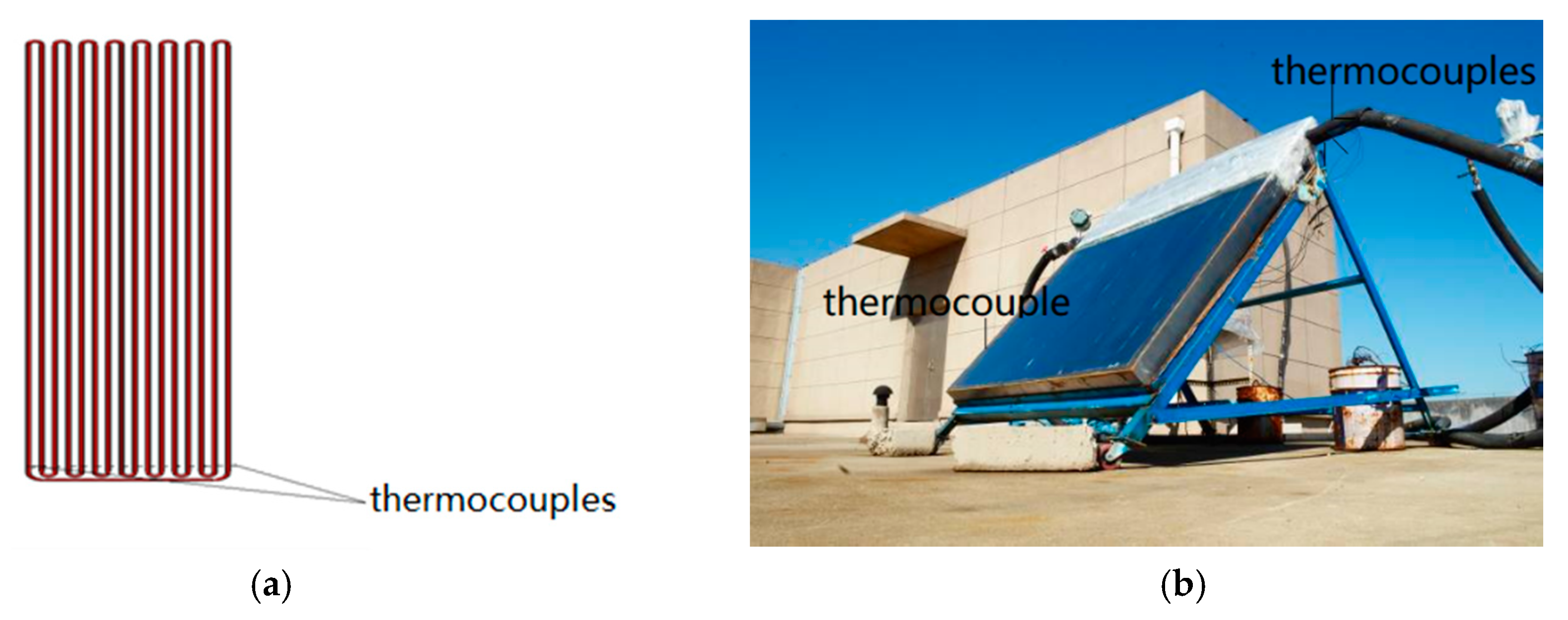
Figure 1 shows the design of the oscillating heat pipe, the outdoor experimental facility and the relative apparatus of the solar collector, including the positions of the thermocouples. The oscillating heat pipe is made up of a capillary tube with a 5 mm outer diameter, 3 mm inner diameter and 16 elbows with a diameter of 18 mm. The total length of the pipe expansion is 19,231 mm. The length of the oscillating heat pipe is 1200 mm, of which the length of the heating section is 1000 mm, with the length of the cooling section being 100 mm, which is set in the pressure channel. After processing the oscillating heat pipe, a molecule pump is needed for vacuuming. Since the total length of the heat pipe is more than ten meters, the pipe diameter is small, and the actual vacuum in the heat pipe is 10
−3 Pa. Distilled water with high purity is used as the working medium, with a liquid filling rate of 50% and a filling rate error of ±2%. It is equipped with thin copper fins in the endothermic section, and is coated with a selective absorption coating on the copper sheet. The absorption rate of the coating exceeds 0.9, enhancing the absorption of solar radiation. The water does not directly pass behind the heat absorbing surface of the collector, effectively solving the problem of freezing in winter, and also potentially solving problems such as corrosion and crusting of the collector.
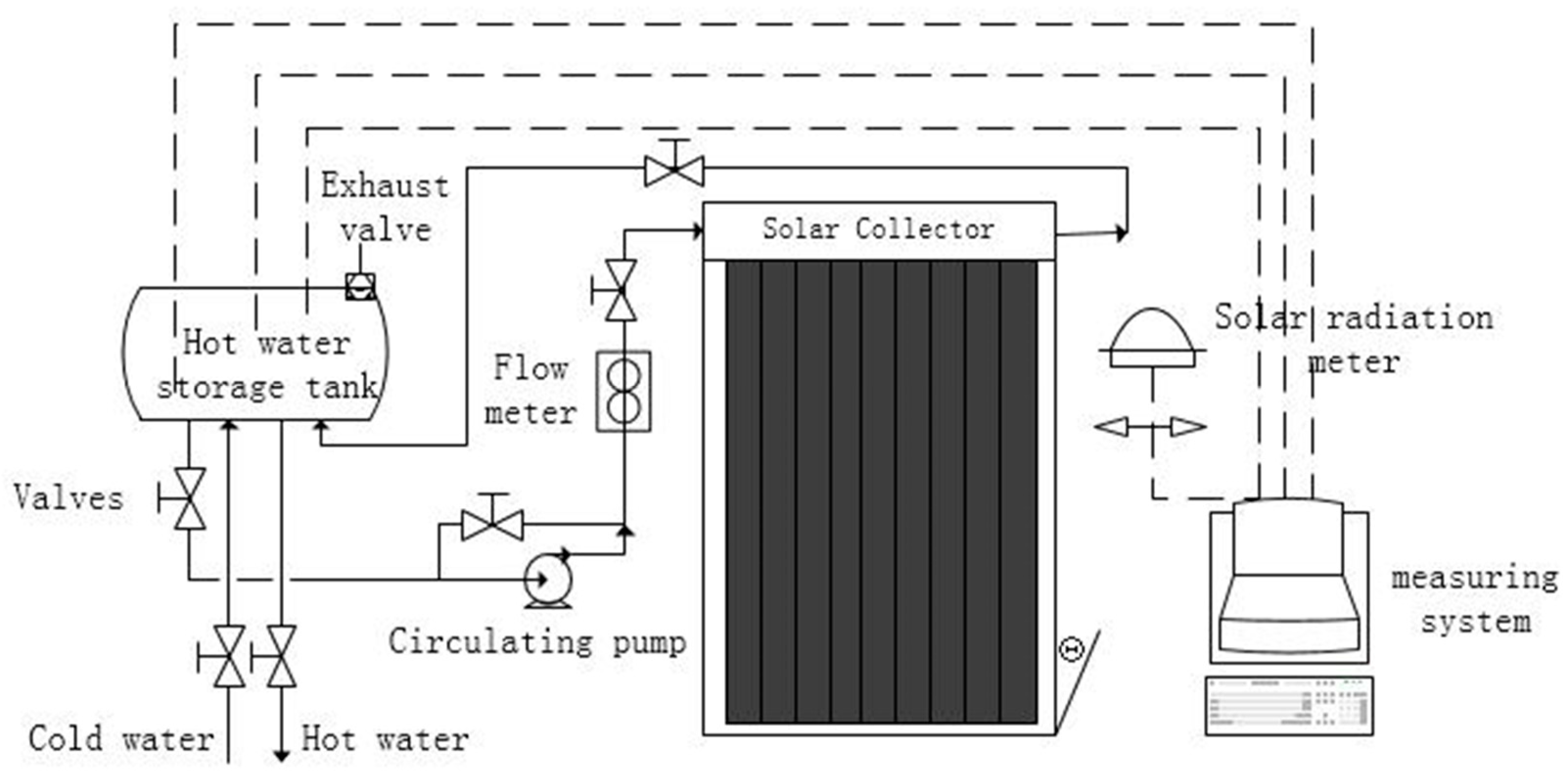
The schematic diagram of the solar water heating system is shown in
Figure 2. The system mainly comprises: a solar collector body, an oscillating heat pipe and a copper plate, a double vacuum glass cover plate, a heat insulating material, and a bracket. The measuring equipment includes: total radiometer, anemorumbometer, computer, data collector, thermocouple, and so on. The collector consists of four oscillating heat pipes side by side. The heat pipe heat absorption section is placed under the glass cover plate, and the cooling section is placed in the water tank. The water tank shell material is stainless steel, which is 3 mm thick and can withstand inside pressure of 0.6 MPa or more. The collector and the external contact parts are tightly and completely wrapped in polyurethane foam material, which has a good thermal insulation function. Three measuring points are arranged at the inlet and outlet of the collector to measure the temperature variation. Sixteen measuring points are located at different parts of the heating section of the oscillating heat pipe. Another ambient temperature measuring point is located near the collector. In addition, a temperature measuring point is also located on the upper side of the glass cover to calculate the energy dissipation of the cover. The position and function of all the experimental apparatus and measurement points employed are displayed in
Table 1. The structure can be rigidly connected, so that the collector has the capacity to withstand the pressure change during the forced circulation process.
2.2. Experimental Methods
The Chinese experimental standard for the method of the thermal properties of the solar collector is adopted in the present experimental research. During the experiment, the total intensity of solar radiation on the solar collector is required to be more than 700 W/m2, but its variation should be less than ±50 W/m2. To improve the accuracy and reliability of experiments, we determine to conduct a thermal efficiency experiment if the radiation intensity exceeds 800 W/m2. The ambient wind speed cannot exceed 4 m/s. Therefore, the time range from 10:00 to 14:00 is chosen in Beijing, China in July and early August. To maximize the annual efficiency of the solar collector and obtain the most solar radiation, the inclination angle of the collector is arranged within the range of ±10° of the local latitude. Because the latitude of Beijing is 39°26’ N, we set the solar collector inclination angle to be 40° for the best angle for collecting solar energy. Here, the inclination angle of the solar collector is defined as the angle between the solar collector and the horizontal direction. The arrangement of the collector faced the south direction with no obstruction around the experimental facility.
The Chinese standard stipulates that at least four uniformly inlet temperature measurement points should be set between 75 °C and the atmosphere temperature. The temperature difference between the inlet of the collector and the atmosphere should be less than ±3 °C. Therefore, we chose the 7 inlet water temperature points, 35 °C, 40 °C, 45 °C, 50 °C, 55 °C, 60 °C, respectively, as our measurement points. The experiment of thermal properties should be carried out using the following steps.
First, a sun shield is selected to partially block the lighting surface of the collector. The distance between the sun shield and the lighting surface of the collector is 10 cm. The collector contains circulating water at ambient temperature to remove the heat from the collector as much as possible. When the temperature at the inlet and outlet of the collector is the same (i.e., the temperature difference does not exceed 1 °C in the actual measurement) and can be maintained, it is considered that the collector has entered a stable state and the experiment can be started.
Second, the inlet temperature of the collector is adjusted to the same inlet water temperature as the ambient temperature (i.e., the temperature difference is less than 1 °C). We adjust the working fluid flux to 72 L/h and keep it constant.
Third, when it is observed that the solar radiance exceeds 800 W/m2 and there is no large area of cloud cover, the sun shield on the lighting surface of the collector is removed, and the experimental data is collected.
2.3. Error Analysis of the Experiment
Error analysis needs to be considered in the experimental process. The relationship between instantaneous efficiency and the corresponding parameters is:
Here,
η is the instantaneous efficiency of the solar collector;
m represents the mass flow of the working medium;
Cp represents the capacity of the working medium at average temperature; Δ
T is the temperature variation between the inlet and the outlet of the solar collector;
An is the daylighting area of the collector;
G represents the radiation intensity on the solar collector. When both sides of Equation (1) are differentiated, we get:
Based on the transitive relation, the simplified format of Equation (2) could be:
We classify the error parameters into five categories:
is the volume measurement error;
is regarded as the physical parameter error;
is the temperature measurement error;
is the length measurement error;
is the solar radiation measurement error. The averages of the various error parameters are as shown in
Table 2. The relative error of the instantaneous efficiency of the solar collector of oscillating heat pipe is ±3%, according to Equation (3), which demonstrates that the experimental results are reliable.
3. Results and Discussion
3.1. Startup Temperature of the Oscillating Heat Pipe
The startup temperature of the oscillating heat pipe is key to thermal properties of the solar collector. Generally, the lower the startup temperature, the better the thermal properties of the collector should be. Therefore, to set a reasonable startup temperature is important to optimize the thermal performance of the collector. To obtain accurate experimental data, the electric heating system is employed to simulate the solar radiation in this section.
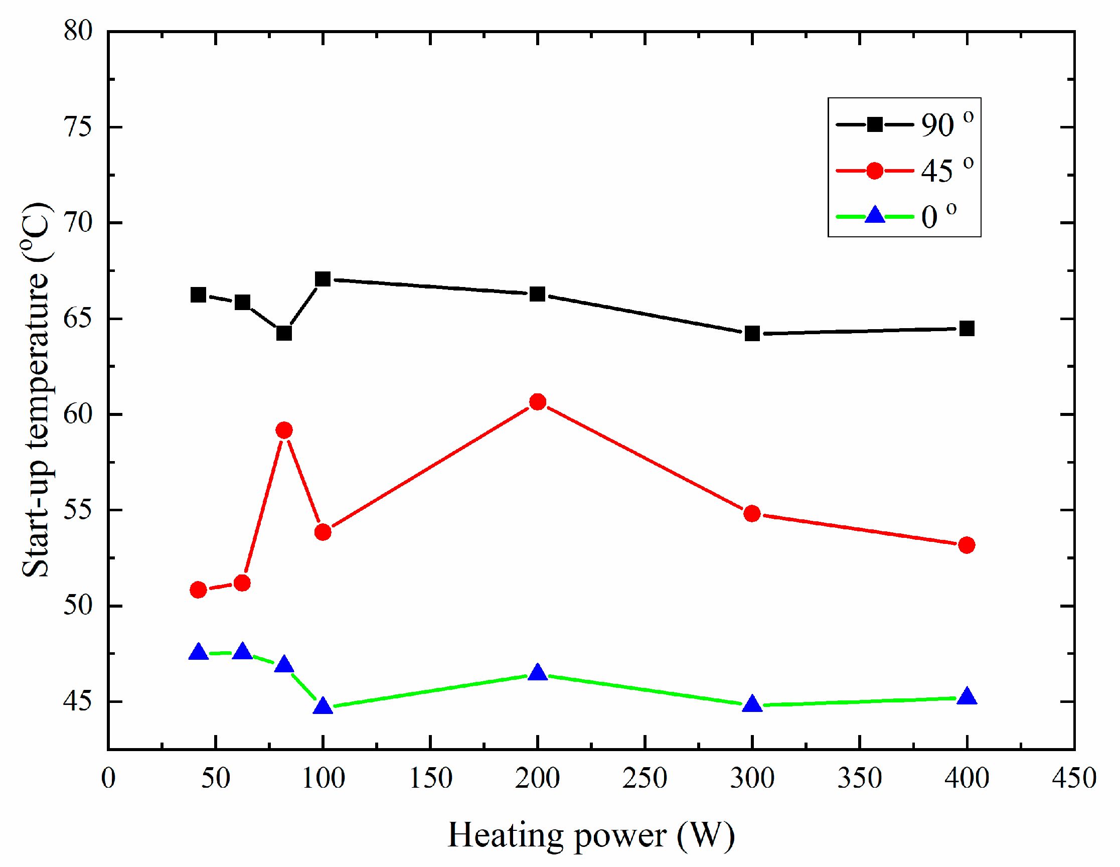
The startup temperature of oscillating heat pipe changing with the heating power for three inclination angles is shown in
Figure 3. The inclination angles of 0 and 90 degrees represent the horizontal and vertical directions of the solar collector, respectively. The startup temperature gets higher with the increase in heating power. This is because the inside of the oscillating heat pipe is in a state in which vapor and liquid coexist. The main source of startup is the evaporation of the liquid, which causes the steam column to expand. When the pressure reaches a certain level, the expanded steam column will displace the liquid column, and the heat pipe starts the oscillation. When the inclination angle of the collector becomes larger, the pressure of the vapor-liquid interface in the oscillating heat pipe increases, and its corresponding saturation temperature also increases. Therefore, the required startup temperature rises with inclination angle increase.
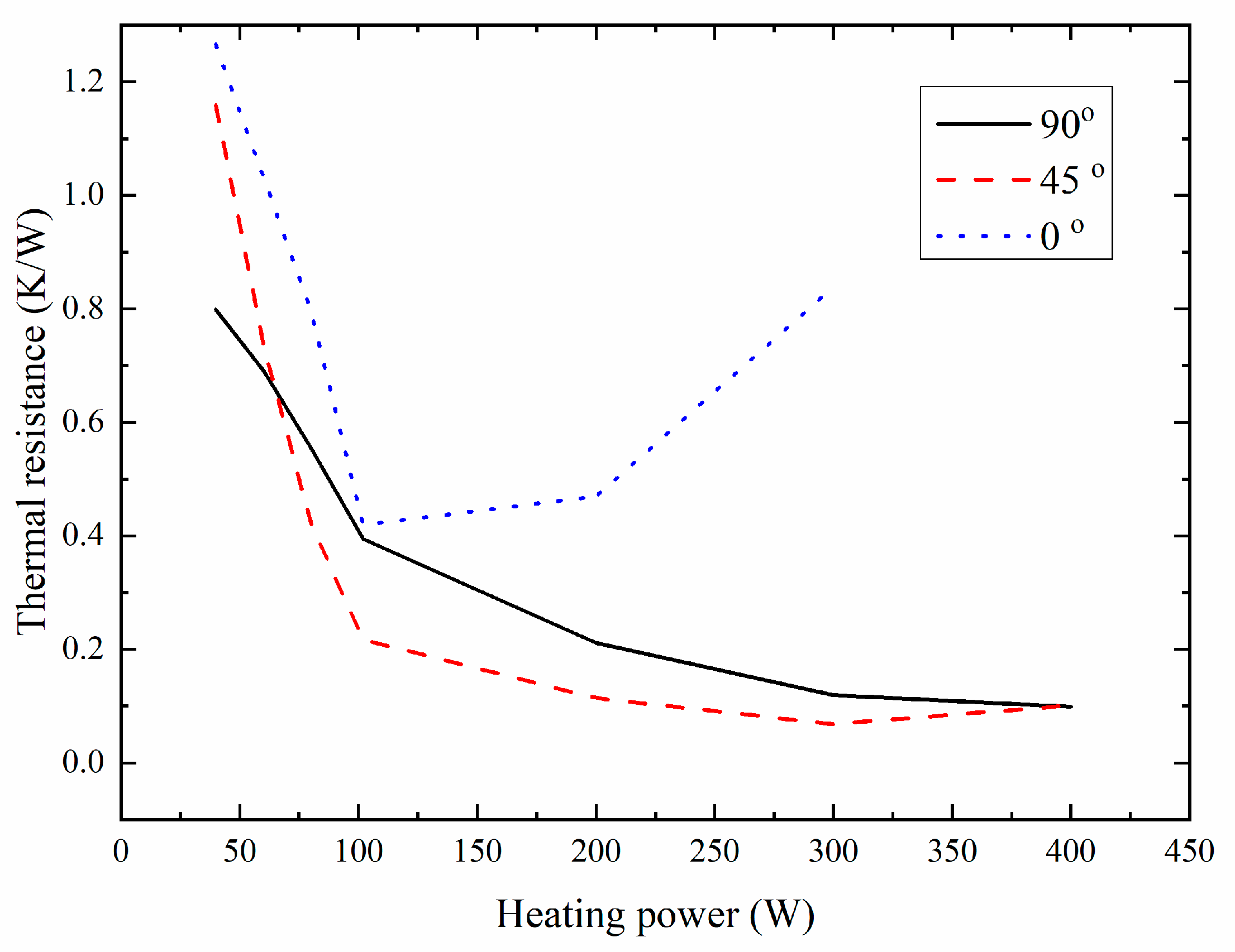
Figure 4 shows the thermal resistance of the solar collector changing with the heating power for different inclination angles. Except when the inclination angle is 0 degrees, the thermal resistance of the oscillating heat pipe at the same inclination angle decreases with increasing heating power of the heating section. Therefore, the pressure and temperature differences of the cooling and heating section increase. In addition, the working medium in the oscillating heat pipe is clearly oscillating. As heating power is further increased, the heat transfer capacity will slowly approach the limit.
In case of the 0° inclination angle, if the heating power is lower than 100 W, the heat resistance in the oscillating heat pipe gradually decreases as the power increases. When heating power exceeds 100 W, the thermal resistance in the oscillating heat pipe gradually increases with the power increase. The main reason for this is that when the inclination angle is 0°, gravity no longer provides extra power for the oscillating heat pipe. When the electric heating power is too high, the working medium of the heating section is evaporated too much. Therefore, the alternating structure of the steam column and the liquid column is destroyed, causing the heat transfer of the oscillating heat pipe to deteriorate. Therefore, the thermal resistance is significantly increased in the high heating power range.
3.2. Instantaneous Efficiency of the Solar Collector
When the collector operates in steady-state status, the ratio of effecitve power for heating water to the solar radiation power received by the collector surface is called instantaneous efficiency of the solar collector.
The instantaneous efficiency of the solar collector of the oscillating heat pipe needs to be expressed as the function of normalized temperature. When using the inlet temperature
Ti of the collector, the normalized temperature difference can be expressed as:
Here,
Ta is the ambient temperature at the same moment. After obtaining the instantaneous efficiency and normalized temperature of the solar collector, we can fit the curve using the least squares method as:
Table 3 shows the experimental data, which are useful for calculation of the instantaneous efficiency of solar collector.
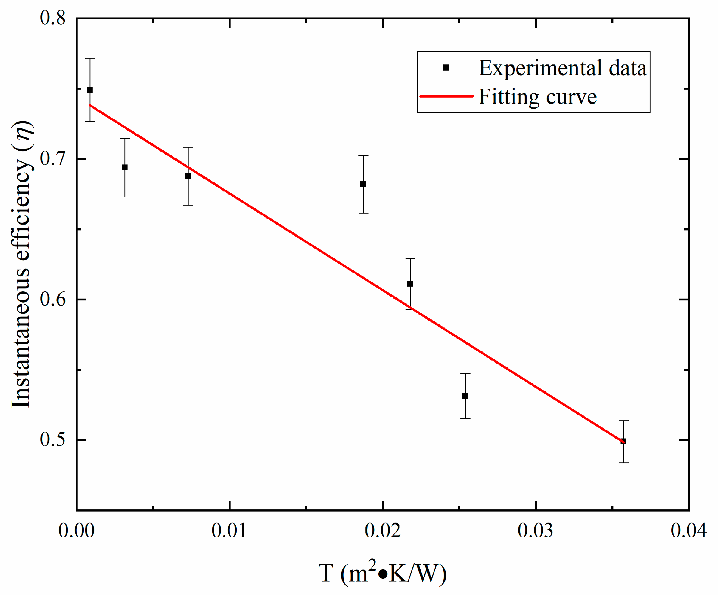
Figure 5 shows the instantaneous efficiency of the solar collector of oscillating heat pipe according to the experimental data. The intercept of the efficiency curve is 0.743 with the heat loss coefficient of the collector being 6.58, solving the problem of large heat loss on the surface of the flat-plate collector. The solar collector can still guarantee a thermal efficiency of more than 50% with the inlet temperature of 60 °C, which solves the problem of low efficiency.
According to the data in
Figure 5, the fitting curve of the instantaneous efficiency will be:
Equation (7) represents the variation of instantaneous efficiency of solar collector changing with the normalized temperature
T.
T reflects the relationship between the inlet water temperature, the ambient temperature and the radiation intensity in Equation (5). It can be found that with the increase of inlet water temperature, the instantaneous efficiency decreases. This is due to the smaller difference between the inlet water temperature and the outside temperature will deteriorate the effect of heat transfer of the oscillating heat pipe. When the ambient temperature is increased, less energy is needed to heat the water and increase the efficiency of the solar collector. In addition, the impact of the solar intensity is similar to the ambient temperature.
Table 4 displays comparisons of different experiments in the literature.
η0 and
U represent the intercept of the fitting curve and heat loss coefficient respectively. Based on these comparisons, it can be found that that the efficiency of the present solar collector is 0.743, which is superior to the similar products in the table. However, the heat loss of the present design is a little higher than the experiment in Ref. [
22], but lower than others. The reason for this is that the middle layer between the oscillating heat pipe and the cover in the solar collector of Ref. [
22] is a vacuum. This design improves the insulation of the system, but it will take extra energy and raise the industrial cost. the instantaneous efficiency of the present solar collector is very high.
3.3. Thermal Properties of the Water Heating System
In this section, the thermal properties of the water heating system are studied experimentally. Before the start of the experiment, the cooling water and the hot water supply from the water heating system are turned off to maintain the water volume of the entire system. Using the circulating pump, the water in the water tank is circulated and the circulation flux is controlled at 72 L/h. The experiment lasted from 8:00 to 16:00. The data, including solar irradiance and water temperature measured by each instrument, were recorded every half hour.
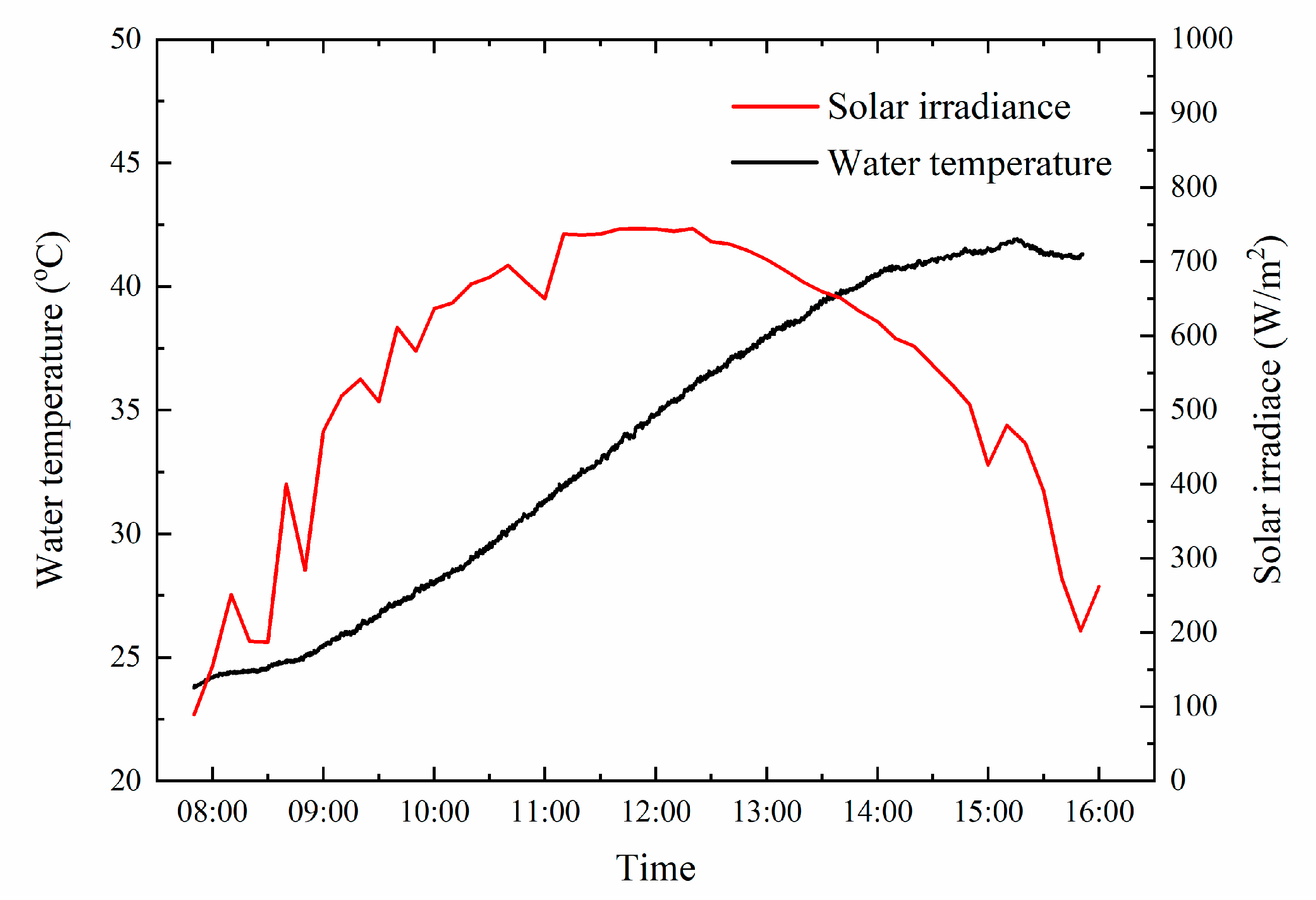
Figure 6 describes the variation of the temperature of the water in the water tank (vertical axis on the left) and the solar radiation (vertical axis on the right) changing with time. The ambient temperature was 24.72 °C at the beginning of the experiment. The maximum radiation intensity was 797.4 J/m
2 with the wind speed of 2.798 m/s during the experiment.
The results show that the temperature variation experienced three stages during the daytime. Firstly, the water temperature increased very slowly before 9:00. This is because the solar intensity was relatively low, and the oscillating heat pipe collector needs some time to absorb the solar energy. Only when the temperature exceeds the startup temperature of the oscillating heat pipe collector, will it start to collect solar energy. During this process, heat conduction is the major means of heat transfer, and the different parts of the solar collector start to absorb heat. Therefore, the energy for heating the water is not enough at this stage. Secondly, from 9:00 to 14:00, the water temperature of the water tank increases smoothly and rapidly. This is because the oscillating heat pipe solar collector is completely in work status, after achieving the startup temperature. The means of heat transfer changes to phase-change heat transfer in the oscillating heat pipe, with very high efficiency. Finally, the temperature of the water in the water tank decreases gradually following a modest increase after 14:00. The decrease of the solar radiation decreases the thermal properties of the solar collector by reducing the temperature between the heating and condensation sections of the collector. In addition, because of the reduction of the solar radiation, the ambient temperature starts to decrease. The heat dissipation of the water heating system to the environment increases, which makes it difficult to further increase the water temperature of the water tank.
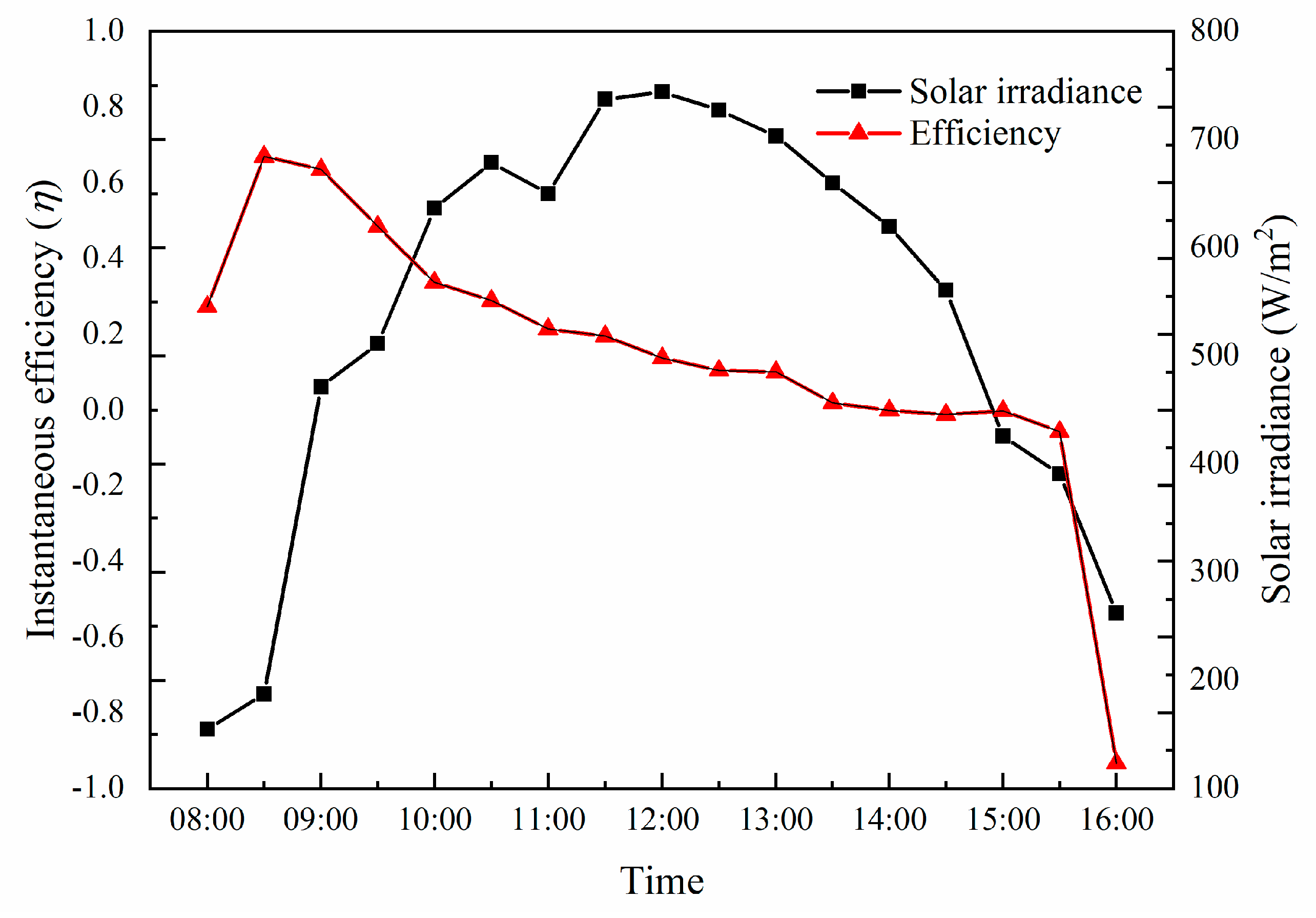
Figure 7 shows the hourly efficiency of the water heating system and the solar irradiance changing with time. It can be seen that the hourly efficiency of the water heating system is not proportional to the solar irradiance. Before 9:30, the temperature difference between the water and the environment is small. At that time, the heat loss of the whole system is also small. Because the solar irradiance and the heat obtained by the collector gradually increases, the hourly efficiency of the water heating system increases. The maximum value of the hourly efficiency reached 0.69 at 9:30. During the time between 9:30 to 13:00, the intensity of the solar irradiance continues to increase, but the effective heat increase rate of the system is slower than the increase rate of the solar irradiance. This phenomenon results in the hourly efficiency of the water heating system decreasing. After 13:00, due to the reduction of the solar irradiance intensity, the water temperature of the water tank reaches a maximum value and no longer absorbs heat. After 14:00, because the solar irradiance and ambient temperature decrease, the temperature difference between the water tank and the atmosphere increases. The external heat dissipation of the system is increased resulting in a negative systemic hourly efficiency. The variation of the efficiency by hour reflects optimal operation conditions of the water heating system, and the solar irradiance change and water temperature determine this condition.


