Numerical Study on Heat Transfer Characteristics of the 36V Electronic Control Unit System for an Electric Bicycle


Abstract
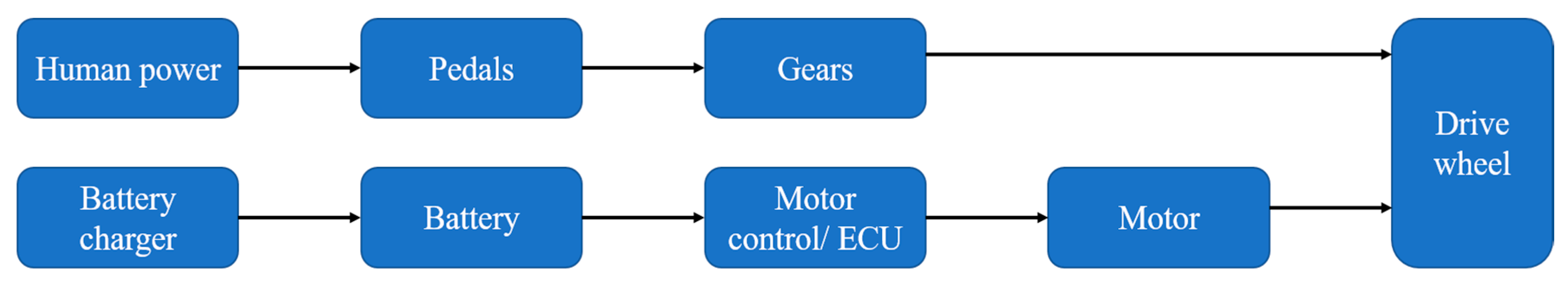
1. Introduction
2. Numerical Method
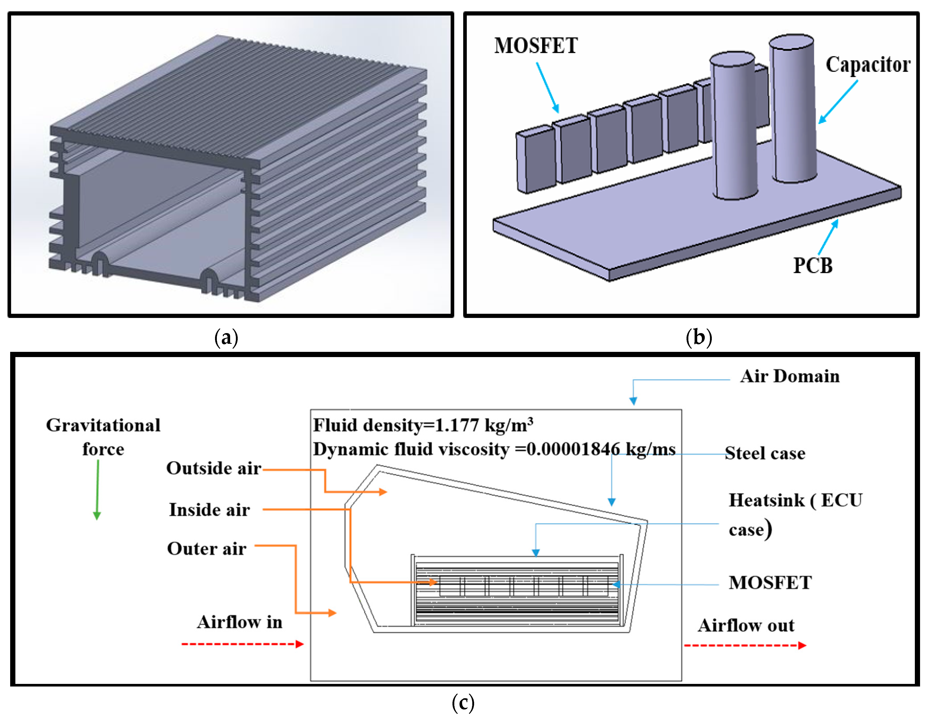
2.1. Numerical Model
2.2. Governing Equations
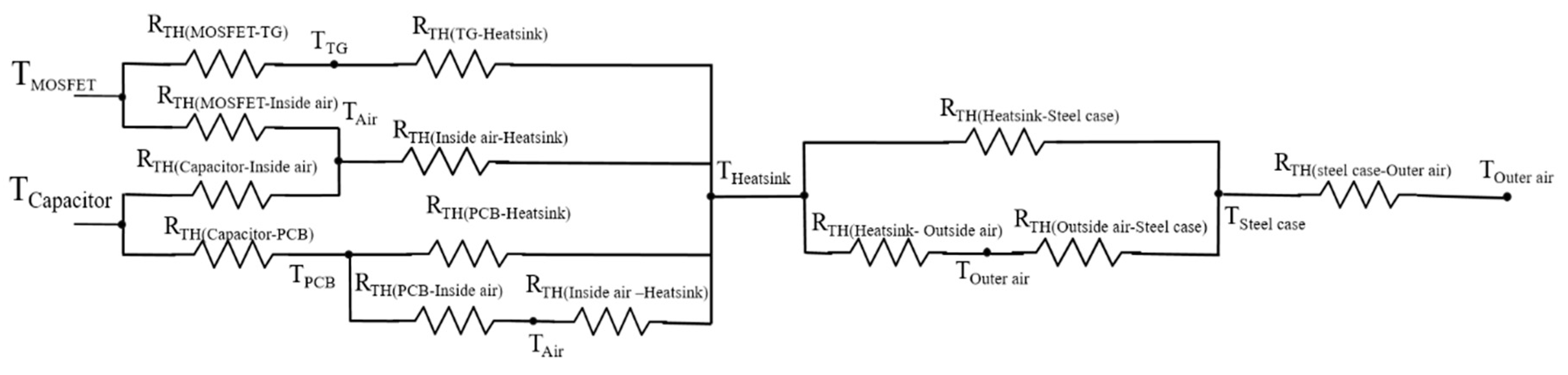
2.3. Data Reduction
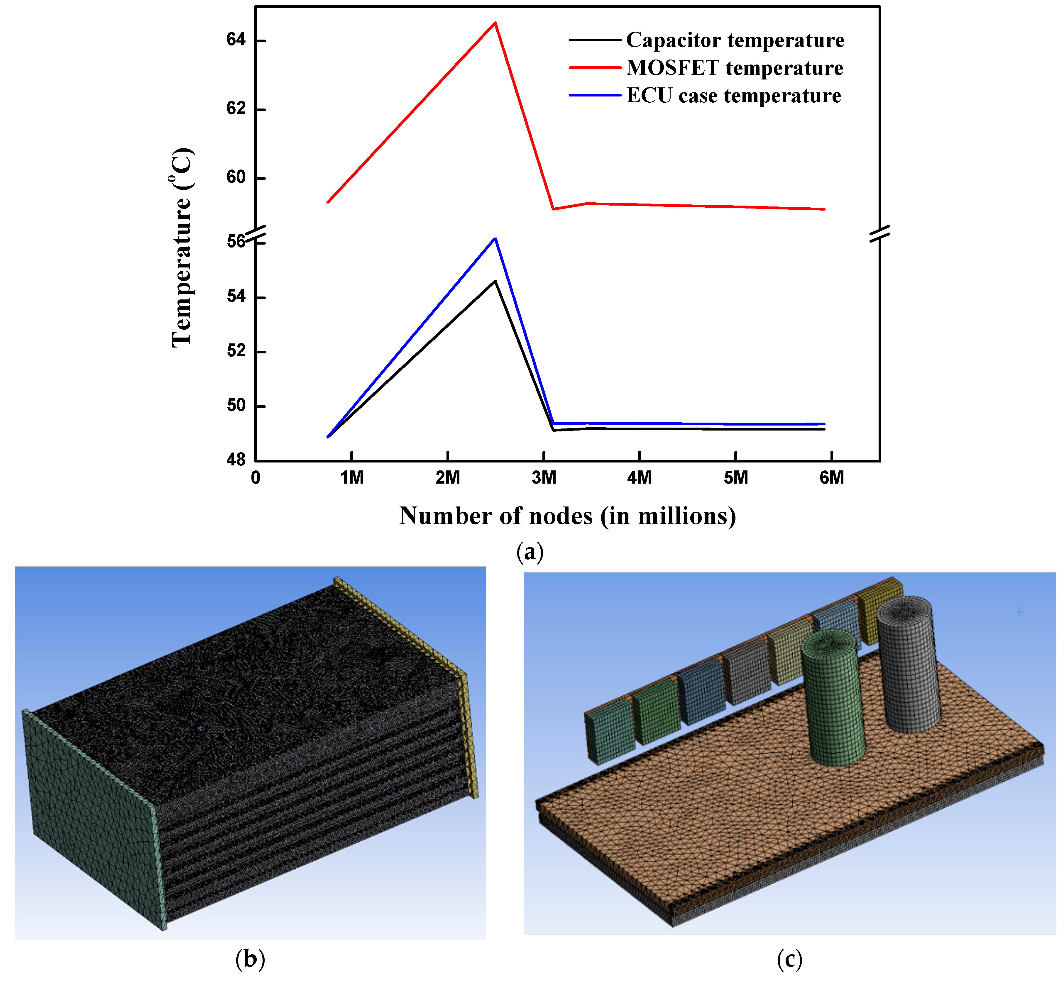
2.4. Numerical Method
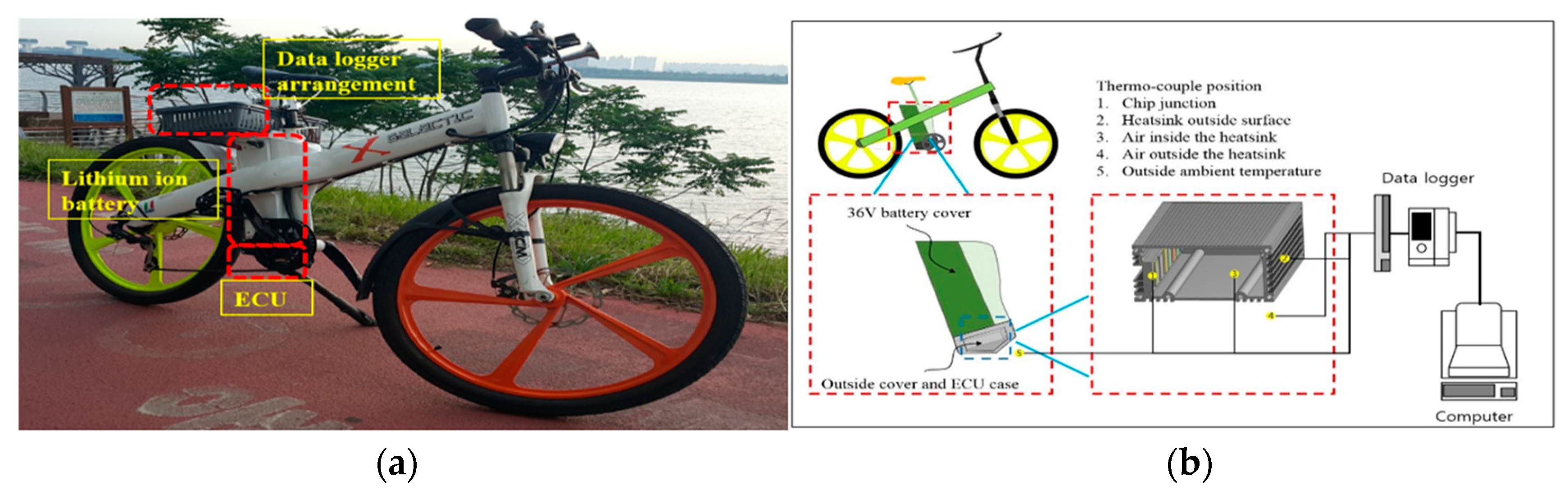
3. Experimental Method
4. Results and Discussion
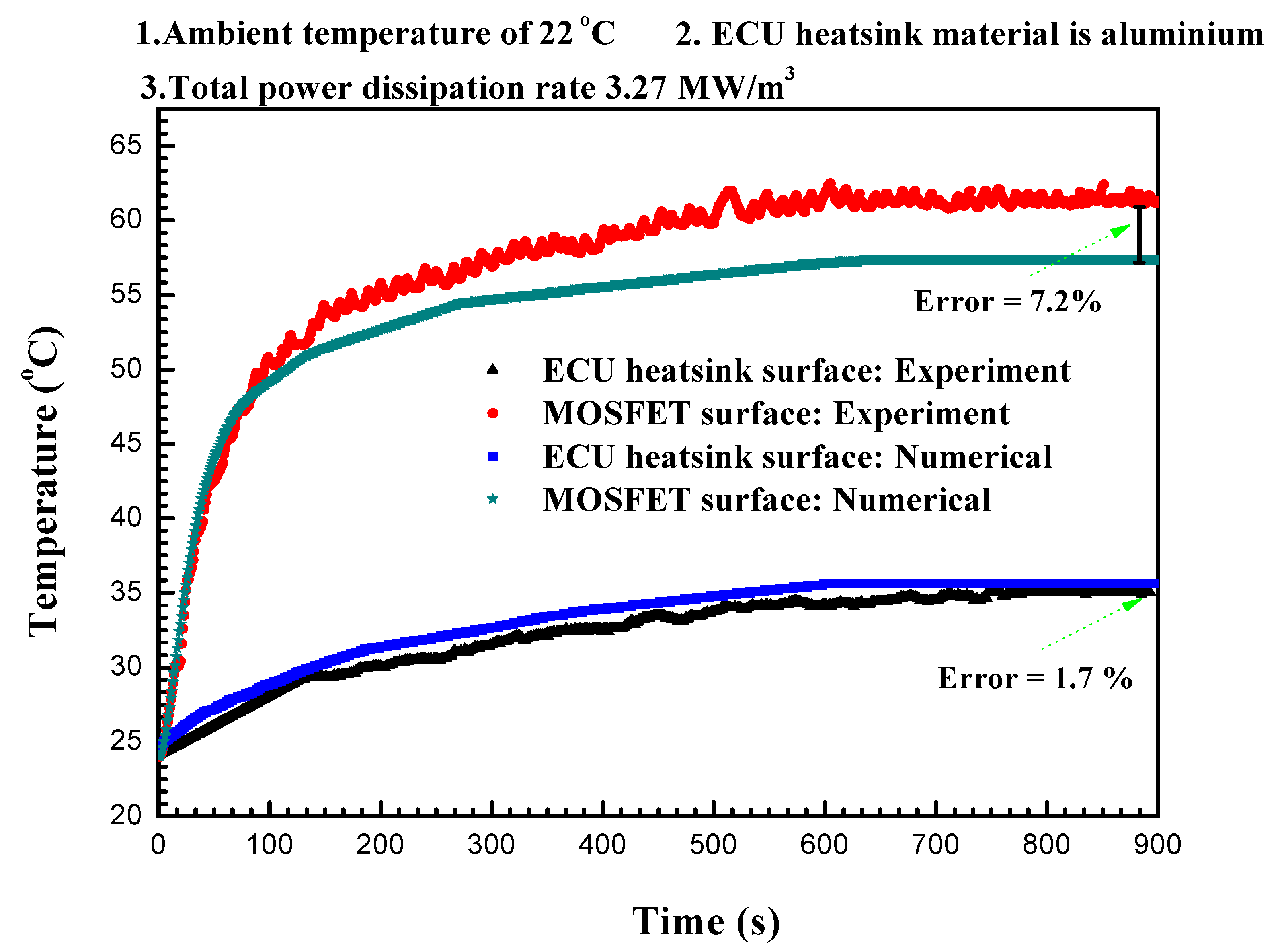
4.1. Validation and Base Test
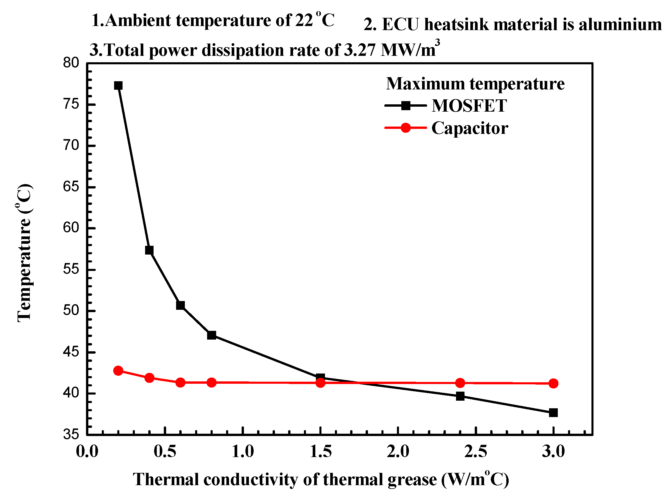
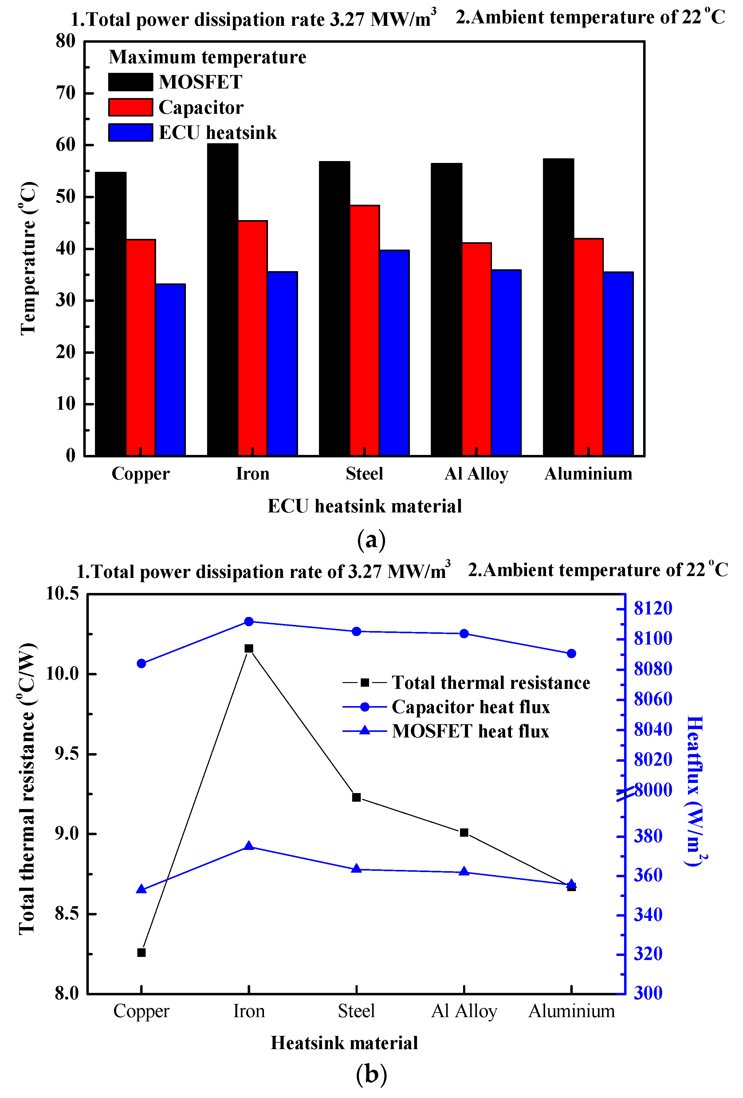
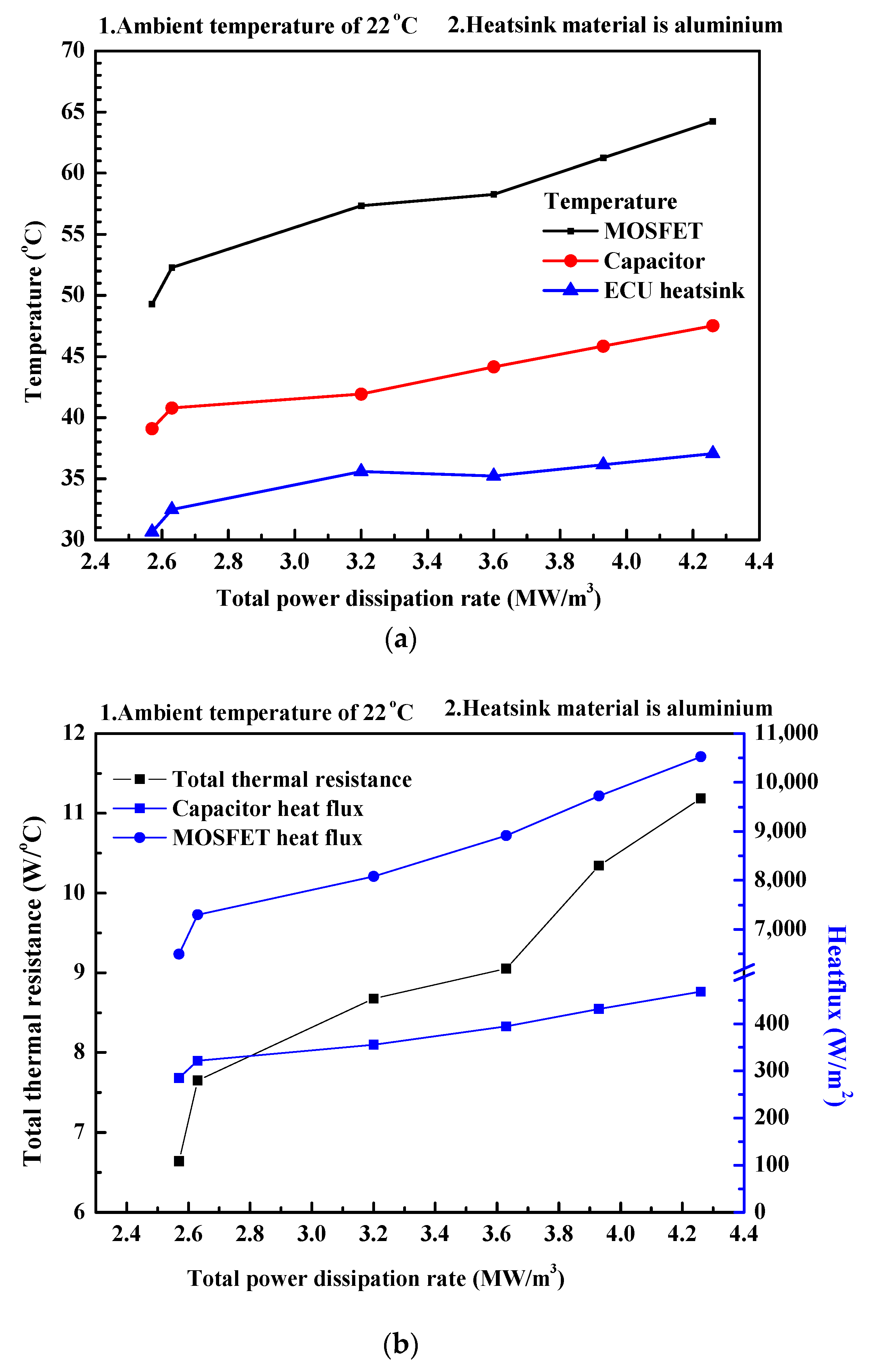
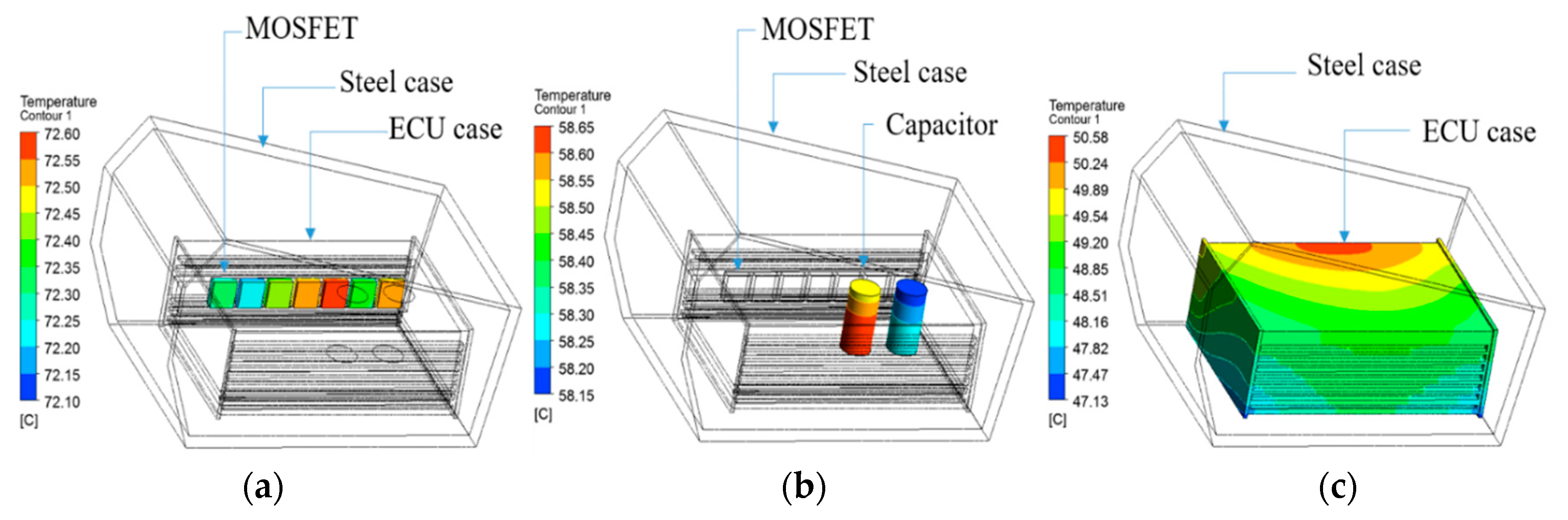
4.2. Temperature Characteristics
5. Conclusions
Author Contributions
Funding
Conflicts of Interest
Nomenclature
| Dynamic fluid viscosity | (Ns/m2) | ||
| Fluid density | (kg/m3) | ||
| A | Surface area | (m2) | |
| cp | Specific heat capacity | (J/kgK) | |
| f | Frequency | (Hz) | |
| GND | Ground connection | ||
| h | Height | (m) | |
| H | Specific Static (thermodynamic) enthalpy | (m2/s2) | |
| I | Current | (A) | |
| k | Thermal conductivity | (W/m K) | |
| L | Characteristic length | (m) | |
| l | Length | (m) | |
| m | Mass of the substance | (kg) | |
| p | Static pressure | (Pa) | |
| PD | Power dissipation | (W) | |
| Q | Thermal energy | (W) | |
| q | Heat transfer rate | (W) | |
| q’ | Heat flux | (W/m2) | |
| R | Resistance | (Ω) | |
| Re | Reynolds number | ||
| RTH | Thermal resistance | °C /W | |
| rms | Root mean square | ||
| SE | Energy Source | (W/m3) | |
| SM | Momentum source | (N/m3) | |
| T | Temperature | (K, °C) | |
| u | Air flow velocity | (m/s) | |
| U | Vector of fluid velocity | (m/s) | |
| V | Voltage | (V) | |
| +VS | Supply voltage (+) | (V) | |
| VOUT | Output voltage | (V) | |
| w | Width | (m) | |
| ΔT | Temperature difference | (K, °C) | |
| τ | Molecular stress tensor | (Pa) | |
| Gradient operator | |||
| Subscript | |||
| ∞ | Ambient | ||
| DS(ON) | Static drain-source on | ||
| E | Energy | ||
| F | Fluid | ||
| IN | Inlet | ||
| OUT | Outlet | ||
| M | Momentum | ||
| PCB | Printed circuit board | ||
| RSS | Small-signal reverse | ||
| S | Solid | ||
| SW | Switching | ||
| TG | Thermal grease | ||
| TH | Thermal | ||
References
- Melino, S.; Petrillo, A.; Cigolotti, V.; Autorino, C.; Jannelli, E.; Ulgiati, S. A Life Cycle Assessment of lithium battery and hydrogen-FC powered electric bicycles searching for cleaner solutions to urban mobility. Int. J. Hydrogen Energy 2017, 42, 1830–1840. [Google Scholar] [CrossRef]
- Mitchell, W.J.; Borroni-Bird, C.E.; Burns, L.D. Reinventing the Automobile-Personal Urban Mobility for the 21st Centuary; The MIT Press Cambridge: Cambridge, MA, USA, 2009; pp. 156–188. [Google Scholar]
- Cairns, S.; Behrendt, F.; Raffo, D.; Beaumont, C.; Kiefer, C. Electrically-assisted bikes: Potential impacts on travel behavior. Transp. Res. Part A 2017, 103, 327–342. [Google Scholar] [CrossRef]
- Vereniging, R.A.I. Statistics Rijwiel en Automobiel Industrie. 2013. Available online: http://www.raivereniging.nl/actueel/go-mobility/go-mobilitynieuwsbrief/20130124-een-miljoenste-ebike-verkocht.aspx (accessed on 3 March 2018).
- Gehlert, T.; Kühn, M.; Schleinitz, K.; Petzoldt, T.; Schwanitz, S.; Gerike, R. The German pedelec naturalistic cycling study e study design and first experiences proceedings. In Proceedings of the International Cycling Safety Conference, Helmond, The Netherlands, 7–8 November 2012; pp. 7–8. [Google Scholar]
- Shuguang, J.; Christopher, R.C.; Lee, D.H.; David, A.J. Electric bike sharing: Simulation of user demand and system availability. J. Clean. Prod. 2014, 85, 250–257. [Google Scholar]
- Weinert, J.; Ogden, J.; Sperling, D.; Burke, A. The future of electric two-wheelers and electric vehicles in China. Energy Policy 2008, 36, 2544–2555. [Google Scholar] [CrossRef]
- Jones, T.; Harms, L.; Heinenc, E. Motives. Perceptions and experiences of electric bicycle owners and implications for health, wellbeing and mobility. J. Transp. Geogr. 2016, 53, 41–49. [Google Scholar] [CrossRef]
- Kennedy, B.; Patterson, D.; Camilleri, S. Use of lithium-ion batteries in electric vehicle. J. Power Sources 2000, 90, 156–162. [Google Scholar] [CrossRef]
- Chen, S.C.; Wan, C.C.; Wang, Y.Y. Thermal analysis of lithium-ion batteries. J. Power Sources 2005, 140, 111–124. [Google Scholar] [CrossRef]
- Dumitrache, F.; Carp, M.C.; Pana, G. E-bike electronic control unit. In Proceedings of the IEEE 22nd International Symposium for Design and Technology in Electronic Packaging, Oradea, Romania, 20–23 October 2016. [Google Scholar]
- Altounmaime, R.; Altounmaime, T.; Padhya, B.P.U. Characteristics and Control of the Motor System in E-Bikes. Master’s Thesis, School of Engineering, Blekinge Institute of Technology, Karlskrona, Sweden, 14 May 2014. [Google Scholar]
- Cong, J. Design of Electric Bicycle Controller. Comput. Inf. Sci. 2009, 2, 126–130. [Google Scholar] [CrossRef]
- Pascot, C.; Dandeville, Y.; Scudeller, Y.; Guillemet, P.; Brousse, T. Calorimetric measurement of the heat generated by a Double-Layer Capacitor cell under cycling. Thermochim. Acta 2010, 510, 53–60. [Google Scholar] [CrossRef]
- Kim, J.K.; Ignatova, V.A.; Heitmann, J.; Oberbeck, L. Deposition temperature effect on electrical properties and interface of high-k ZrO2 capacitor. J. Phys. Appl. Phys. 2008, 41, 1–6. [Google Scholar] [CrossRef]
- Bang, Y.M.; Patil, M.S.; Kim, D.W.; Seo, J.H.; Lee, M.Y. Numerical Study on the Thermal Performance of Battery Applying Cell Array Guide for NEV. In Proceedings of the KSME Thermal Engineering Division, Yeosu, Korea, 16 June 2016; pp. 362–363. [Google Scholar]
- ANSYS® Academic Research, Release 16.2; ANSYS: Pittsburgh, PA, USA, 2015.
- Soni, A. Study of thermal performance between plate-fin, pin-fin, and elliptical fin heat sink in closed enclosed under natural convection. Int. Adv. Res. J. Sci. Eng. Technol. 2016, 3, 133–139. [Google Scholar]
- Patil, M.S.; Seo, J.H.; Kim, D.W.; Kim, C.J.; Lee, G.S.; Kim, M.Y.; Kim, K.-H.; Lee, M.Y. Thermo-fluid Simulation for the thermal performances of the 72V ECU cooling system with heatsink for a light electric vehicle. J. Adv. Res. Dyn. Control Syst. 2018, 10, 199–210. [Google Scholar]
- Newman, J. Physics of the Life Sciences. Available online: http://www.if.ufrj.b/~coelho/Newman/Newman12.pdf (accessed on 3 March 2018).
- Christensen, A.; Graham, G. Thermal effects in packaging high power light emitting diode arrays. Appl. Therm. Eng. 2009, 29, 364–371. [Google Scholar] [CrossRef]
- Holman, J.P. Heat Transfer, 10th ed.; The McGraw-Hill Companies: New York, NY, USA, 2010; pp. 48–120. [Google Scholar]
- Lee, H.S.; Cho, C.W.; Seo, J.H. Cooling performance characteristics of the stack thermal management system for fuel cell electric vehicle under actual driving conditions. Energies 2016, 9, 320. [Google Scholar] [CrossRef]
- Lienhard, J.H. On the Commonality of Equations for Natural Convection from Immersed Bodies. Int. J. Heat Mass Transf. 1973, 16, 2121–2123. [Google Scholar] [CrossRef]
- Climate: Observations Projections and Impacts—South Korea. Available online: http://eprints.nottingham.ac.uk/2040/19/Republic_of_Korea.pdf (accessed on 3 March 2018).
- Data Sheet of SiHFZ34 MOSFET. Available online: https://www.vishay.com/docs/91290/91290.pdf (accessed on 3 March 2018).
- Data Sheet of CD288H Capacitor. Available online: http://www.vek-online.de/files/4188/upload/Elektrolyt/CD288H.pdf (accessed on 3 March 2018).
- Gwinn, J.P.; WebbR, L. Performance and testing of thermal interface materials. Microelectron. J. 2003, 34, 215–222. [Google Scholar] [CrossRef]
- Thermal Interface Materials for Electronics Cooling-Products and Custom Solutions Catalog. Available online: https://www.parker.com/literature/Chomerics/Parker%20Chomerics%20Thermal%20Catalog.pdf (accessed on 3 March 2018).
- Al-Hagag, Q.R.; Bassil, M.H.; Al-Janab, M.Y. Optimum Design of Rectangular Plate Heat Sink. Available online: http://www.uobabylon.edu.iq/uobcoleges/fileshare/articles/opt,final2.pdf (accessed on 3 March 2018).
- Terry, M.T. Thermal Conductivity: Theory, Properties and Applications; 2nd Series; Kluwer Academic/Plenum Publishers: New York, NY, USA, 2004; pp. 21–88. [Google Scholar]
- Mondolfo, L.F. Aluminium Alloys: Structure and Properties, 1st ed.; Buttereorth & Co Ltd.: London, UK, 1979; pp. 56–68. [Google Scholar]
- Wasserman, E.; Stixrude, L.; Cohen, R.E. Thermal properties of iron at high pressures and temperatures. Phys. Rev. B 1996, 53, 82–96. [Google Scholar] [CrossRef]
- Iyengar, M. Design For Manufacturability Of Forced Convection Air Cooled Fully Ducted Heat Sinks. Electron. Cool. Mag. 2007, 13, 22–26. [Google Scholar]
- Mallik, S.; Ekere, N.; Best, C.; Bhatti, R. Investigation of thermal management materials for automotive electronic control units. Appl. Therm. Eng. 2011, 31, 355–362. [Google Scholar] [CrossRef]
- Sullivan, O.C. Newton’s law of cooling—A critical assessment. Am. J. Phys. 1990, 58, 956–960. [Google Scholar] [CrossRef]
- The Physics Factbook. Available online: https://hypertextbook.com/facts/2004/KarenSutherland.shtml (accessed on 3 March 2018).
- Worrell, E.; Price, L.; Martin, N.; Farla, J.; Schaeffer, R. Energy Intensity in the Iron and Steel Industry: A comparison of physical and economi Indicators. Energy Policy 1997, 25, 727–744. [Google Scholar] [CrossRef]
- Keller, K. Low Cost, High Performance, High Volume Heatsinks. Available online: http://www.cs.unc.edu/~pxfl/papers/low_cost1.pdf (accessed on 3 March 2018).
- Schiffer, J.; Linzen, D.; Sauer, D.U. Heat generation in double layer capacitors. J. Power Sources 2006, 160, 765–772. [Google Scholar] [CrossRef]
- Olson, J.R. Thermal conductivity of some common cryostat materials between 0.05 and 2 K. Cryogenics 1993, 7, 729–731. [Google Scholar] [CrossRef]
- Tse, R.; Cannon, M.; Coe, J. Frequently Asked Questions Regarding: ESR Perfomance with Temperature; TDK Components Inc.: Lincolnshire, IL, USA. Available online: http://www.digikey.kr/Web%20Export/Supplier%20Content/TDK_445/PDF/TDK_esr.pdf (accessed on 3 March 2018).


| Item | Specifications |
|---|---|
| Overall size (w × l × h, mm3) | 65.7 × 98.6 × 32.9 |
| Maximum thickness (mm) | 4.5 |
| Minimum thickness (mm) | 2 |
| Maximum fin length (mm) | 98.6 |
| Maximum fin height (mm) | 2.7 |
| Maximum fin pitch (mm) | 3.9 |
| Total surface area (mm2) | 65,171 |
| Component | Material | Thermal Conductivity (W/m °C) | Density (kg/m3) | Specific Heat Capacity (J/kg °C) |
|---|---|---|---|---|
| Heatsink | Aluminum | 237 | 2702 | 930 |
| Capacitor | Aluminum oxide | 30 | 3890 | 880 |
| MOSFET | Silicon | 150 | 2390 | 7120 |
| Thermal grease | Silicon carbide | 0.42 | 2500 | 750 |
| PCB | Copper and Plastic | 0.4 | 855 | 2300 |
| Variables | Specifications |
|---|---|
| Capacitor and MOSFET total power dissipation (MW/m3) | 2.57, 2.63, 3.20, 3.60, 3.93, 4.26 |
| Thermal conductivity of thermal grease material (W/m °C) | 0.01, 0.2, 0.4, 0.6, 0.8, 1.5, 2.4, 5 |
| Ambient temperatures (°C) | −20, −10, 0, +10, +20, +30, +40 |
| Heatsink manufacturing material | Aluminum, Iron, Steel, aluminum alloy, Copper |
| Item | Specification |
|---|---|
| Nominal voltage (V) | 36.0 |
| Nominal capacity (Ah) | 10.4 |
| Charging voltage (V) | 42.0 |
| Discharging current (A) | 10.0 |
| Item | Specification |
|---|---|
| Velocity (km/h) | 30 |
| Ambient temperature (°C) | 22 |
| Test time (s) | 1500 |
| Average weight of the rider (kg) | 70 |
| Bicycle weight (kg) | 26 |
© 2018 by the authors. Licensee MDPI, Basel, Switzerland. This article is an open access article distributed under the terms and conditions of the Creative Commons Attribution (CC BY) license (http://creativecommons.org/licenses/by/4.0/).
Share and Cite
Ekanayake, G.; Patil, M.S.; Seo, J.-H.; Lee, M.-Y. Numerical Study on Heat Transfer Characteristics of the 36V Electronic Control Unit System for an Electric Bicycle. Energies 2018, 11, 2506. https://doi.org/10.3390/en11102506
Ekanayake G, Patil MS, Seo J-H, Lee M-Y. Numerical Study on Heat Transfer Characteristics of the 36V Electronic Control Unit System for an Electric Bicycle. Energies. 2018; 11(10):2506. https://doi.org/10.3390/en11102506
Chicago/Turabian StyleEkanayake, Gihan, Mahesh Suresh Patil, Jae-Hyeong Seo, and Moo-Yeon Lee. 2018. "Numerical Study on Heat Transfer Characteristics of the 36V Electronic Control Unit System for an Electric Bicycle" Energies 11, no. 10: 2506. https://doi.org/10.3390/en11102506
APA StyleEkanayake, G., Patil, M. S., Seo, J.-H., & Lee, M.-Y. (2018). Numerical Study on Heat Transfer Characteristics of the 36V Electronic Control Unit System for an Electric Bicycle. Energies, 11(10), 2506. https://doi.org/10.3390/en11102506