Review

Installation of XLPE-Insulated 400 kV Submarine AC Power Cables under the Dardanelles Strait: A 4 GW Turkish Grid Reinforcement

1
Department of Industrial Engineering, University of Padova, 35122 Padova, Italy
2
Turkish Electricity Transmission Corporation (TEIAŞ), 06520 Ankara, Turkey
*
Author to whom correspondence should be addressed.
Energies 2018, 11(1), 164; https://doi.org/10.3390/en11010164
Submission received: 20 December 2017 / Revised: 7 January 2018 / Accepted: 8 January 2018 / Published: 10 January 2018
(This article belongs to the Section F: Electrical Engineering)

Abstract

:
This paper describes the 400 kV AC submarine link under the Dardanelles Strait composed of 12 submarine armoured single-core cross-linked polyethylene (XLPE)-insulated cables (plus a back-up power cable). The link consists of two parallel-operated double-circuit links named Lâpseki–Sütlüce I and Lâpseki–Sütlüce II. The transmissible power is 4000 MW (1000 MW per circuit) and the average length for a single-core cable is about 4.6 km: the submarine cables are part of overhead lines. This paper gives a wide account of the cable installations and, chiefly, of the cable protections on the seabed: different protection choices were extensively used (i.e., water jetting and mattressing).

1. Introduction

The Turkish high voltage (HV) transmission grid is highly modern. In the first years of HV electrification (around 1968), the Turkish grid was constituted by 154 kV overhead lines supplying only the most important cities: in those years, the load peak was about 1.5 GW. Nowadays, the load peak is about 47.5 GW with an energy demand of about 250 TWh. The modernization and reinforcement of the Turkish grid have been witnessed by Professor Francesco Iliceto in his consultant activity and in his papers [1,2,3,4].
The transmission network is composed of about 21,000 km of Extra High Voltage (EHV) lines (400 kV) and 39,000 of HV lines (154 kV). The power plants have a rated power of about 81 GW (almost equally shared between hydroelectric, coal thermoelectric, and turbo-gas plants). A great achievement of the Turkish transmission system operator (TEIAŞ) is the interconnection with the ENTSO-E grid. Turkey is interconnected with the Bulgarian and Greek grids by means of three 400 kV A.C. overhead interties. The synchronous parallel is strongly helped by the use of Special Protection Systems (with acronym SPSs) also called System Integrity Protection Schemes. These SPSs are installed in the two Turkish interconnection substations (with the aforementioned Greek and Bulgarian grids). The active powers flowing through these three interties are measured and updated every 50 ms. These measurements are then sent to the SPS computing system which sums them and computes the time derivative and its average value every 1.5 s. If this average value and the above-mentioned algebraic sum exceed prefixed thresholds (expressed in MW/s and in MW) along with a sign indicating that the power import is increasing, SPSs control the load shedding of 12 substations (154/34.5 kV) for a total of 1200 MW.

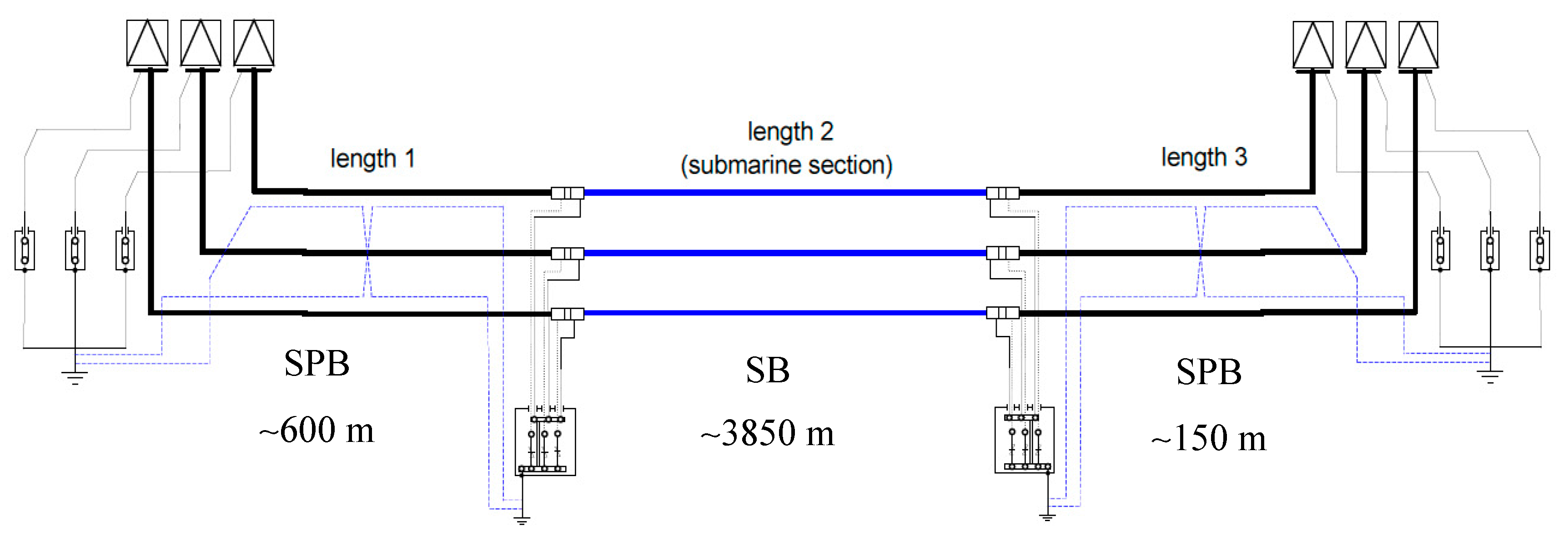
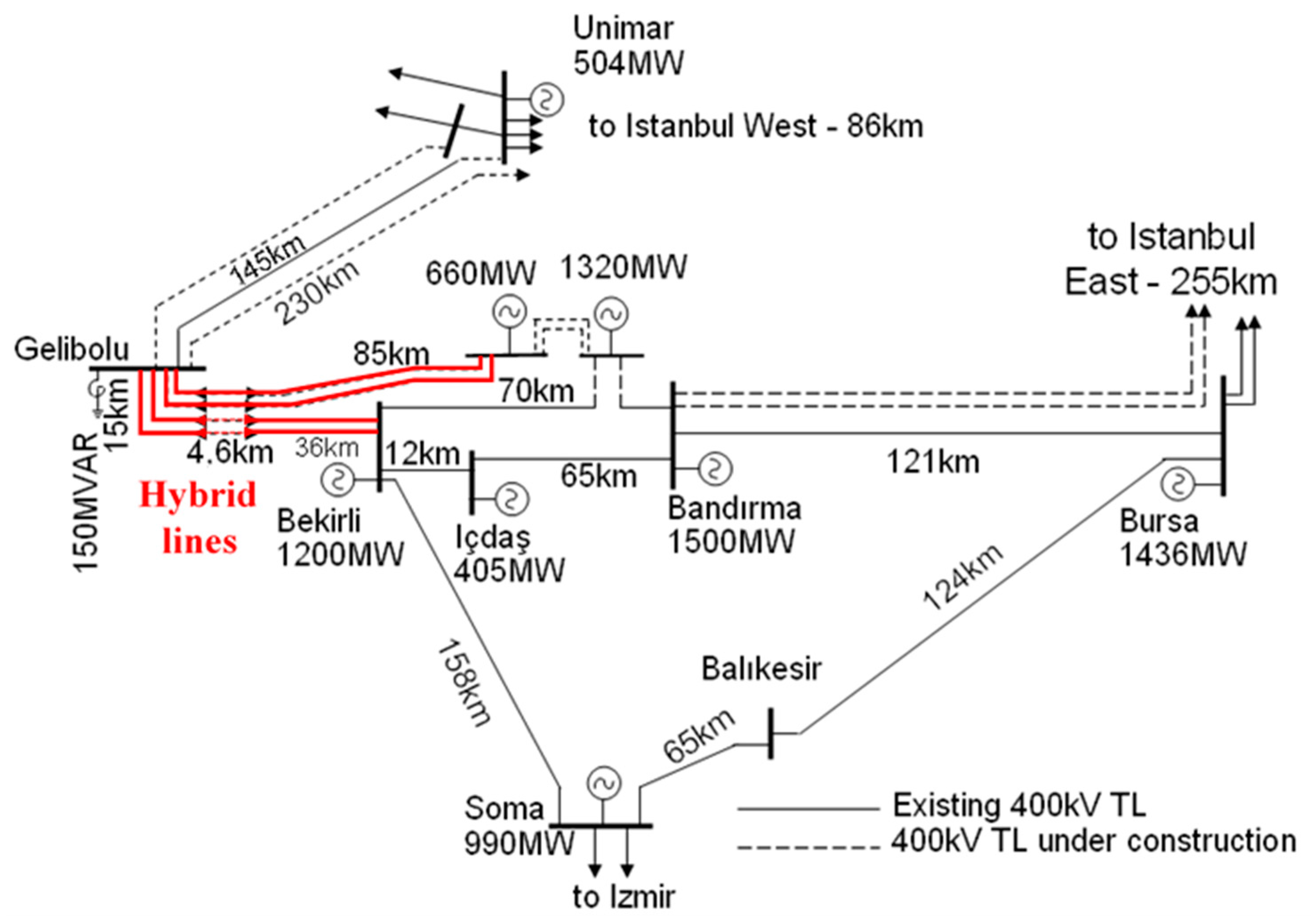
2. Description of the Link

In this scenario, the installation of the cable systems and the erection of the associated 400 kV overhead lines were economically justified in order to transmit a large power amount generated by the power plants (located along the Southern coast of the Marmara Sea) to Istanbul, via the Western corridor (Trakya) [5]. The cable systems link the Lâpseki substation (Asian side) with the Sütlüce one (European side) across the Dardanelles Strait. The land and submarine cables are shown in Figure 1, whereas Table 1 gives all their geometrical characteristics. With regard to Lâpseki–Sütlüce I [5], the cable system consists of a proper submarine part (about 3850 m) and two land stretches (the Lâpseki part about 600 m and the Sütlüce part about 150 m). The submarine part is operated in solid bonding (with acronym SB), whereas the two land parts are operated in single-point bonding (with acronym SPB) as shown in Figure 2.
As already mentioned, the cable lines are part of a mixed or hybrid line (cascade connections of overhead–cable–overhead lines), as shown in Figure 3, which renders these links extremely interesting from an electrical engineering research standpoint [6,7,8,9,10,11,12,13,14,15,16,17,18,19,20,21].

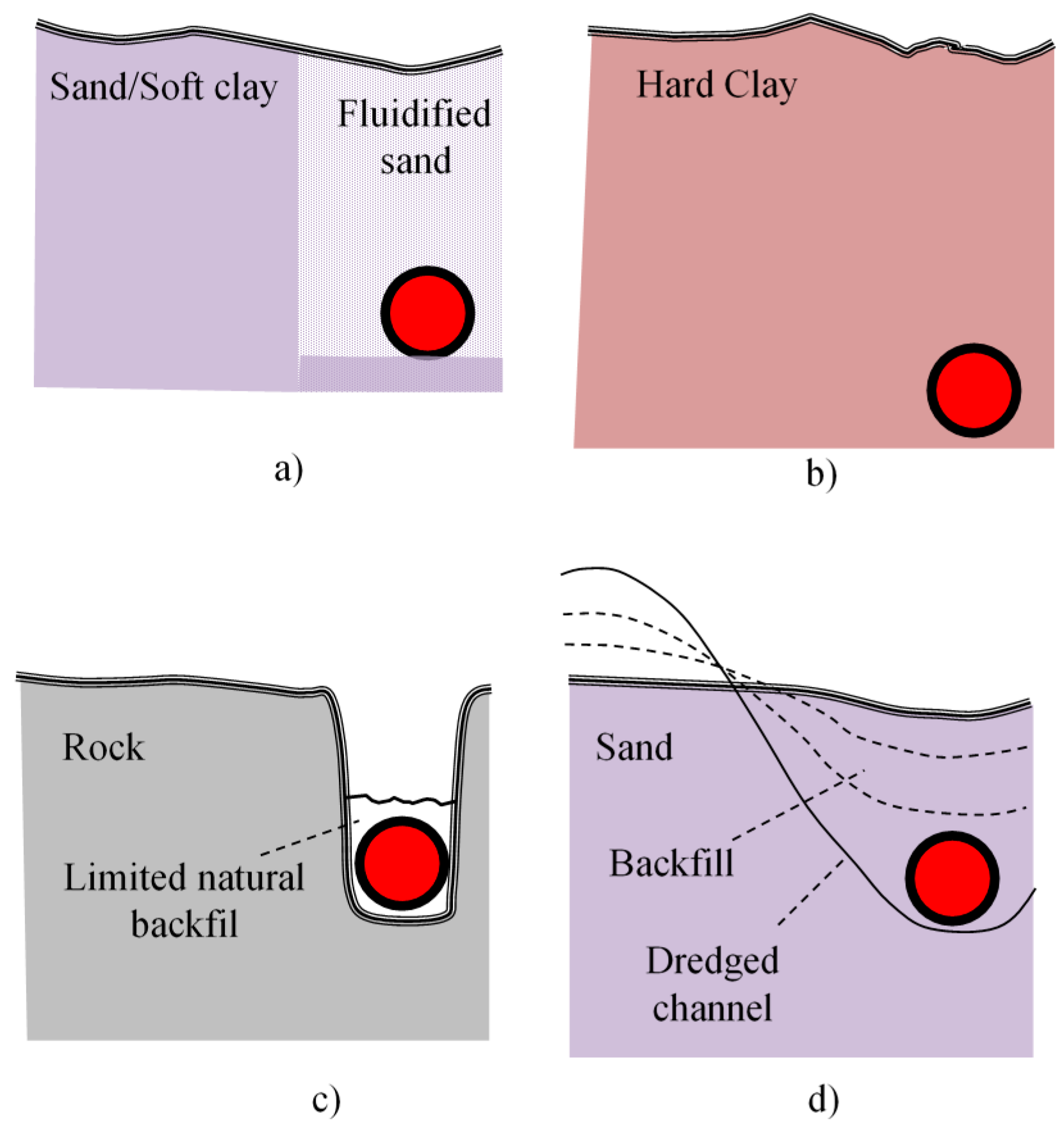
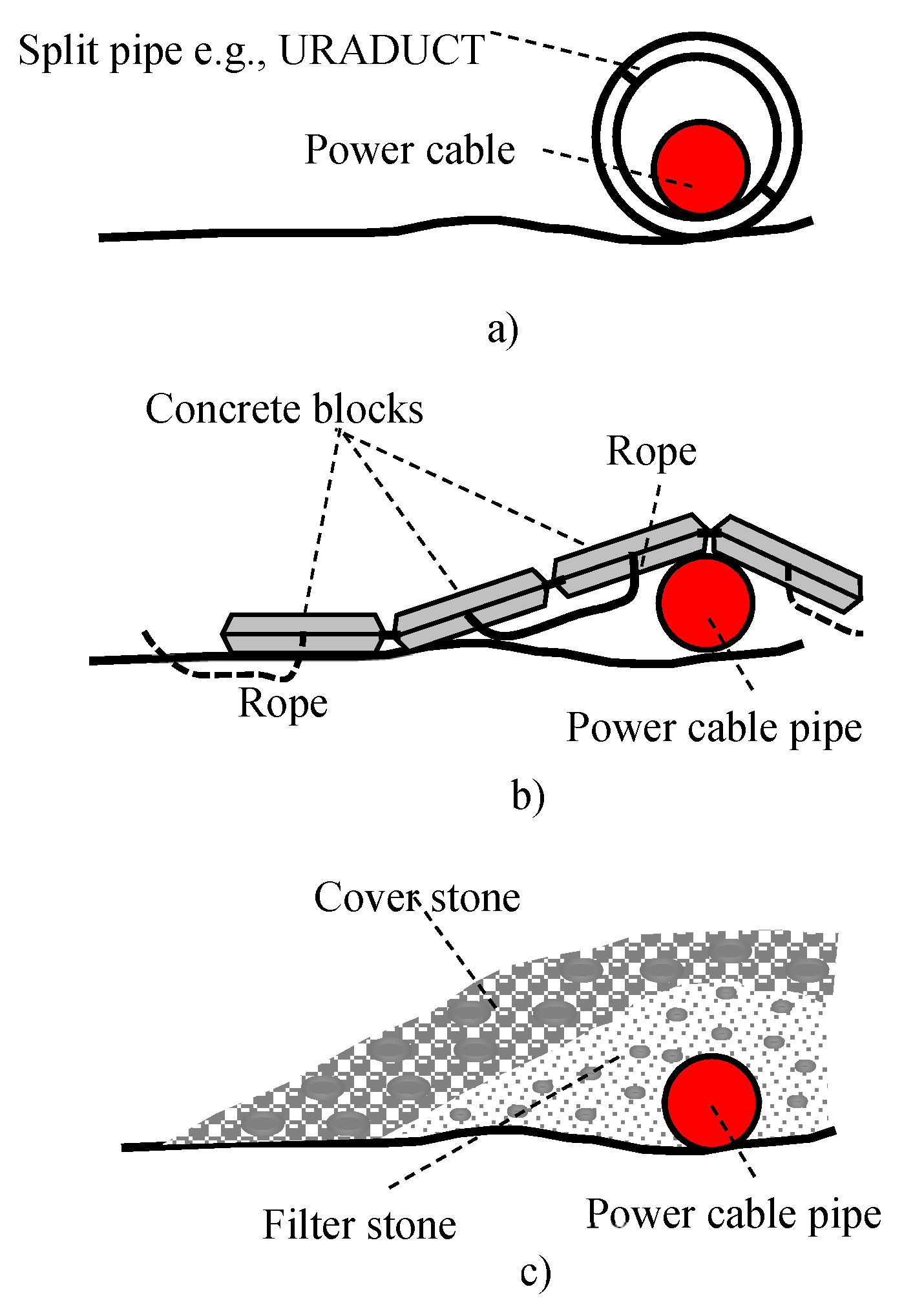
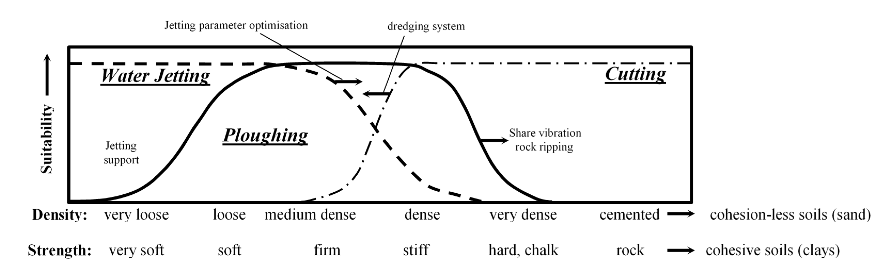
3. A Brief Overview of the Submarine Cable Protection Techniques

It is worth mentioning that the first submarine cable for telegraphic purpose, installed between England and France in 1850, was inadvertently cut by a French fisherman within the first 24 h of operation [22]. In 1858, the first transatlantic cable (always for telegraphic purposes) between Ireland and Newfoundland was just a little bit luckier and failed after 26 days of operation. Many submarine cables were installed unprotected on the seabed in shallow water stretches until the 1980s and 1990s. Without cable protections, third-party damages are a frequent reality. The engineering community has always felt this issue so strongly that a paper [23] dated 1938 and emblematically entitled “Protection of Submarine Cable by Placement Underground” stated that:
“a plow has been devised by engineers of the Western Union Telegraph Company which when pulled along the ocean bottom is expected to cut a furrow, drop the cable into it, and back fill over the cable”.
When suitable subsea burial tools (e.g., jetting, trenching, and dredging machines) became available in the 1980s, the burial and covering protections of more and more longer cable stretches became a common engineering practice. However, in 1986, only a small portion of submarine power cables was externally protected [24]. Today, almost all submarine power cables are externally protected by burial or covering (e.g., by means of mattresses or tubular products, or rock dumping) (see Figure 4 and Figure 5).
It is worth remembering that these protections play also a key role in order to avoid possible sabotages. Figure 6 shows the suitability of different burial techniques depending on the seabed conditions [25]. The scales for cohesive and cohesionless soils are approximately reported on the x-axis. The suitability of the different tools is reported on the y-axis.
Table 2 reports a comparison among different burial techniques [25], and the text highlighted in grey regards situations of a certain importance for the Lâpseki–Sütlüce installation.
Of course, the real installation or laying phase is only the last step of a long and precise process, which foresees, at least, the following milestones:
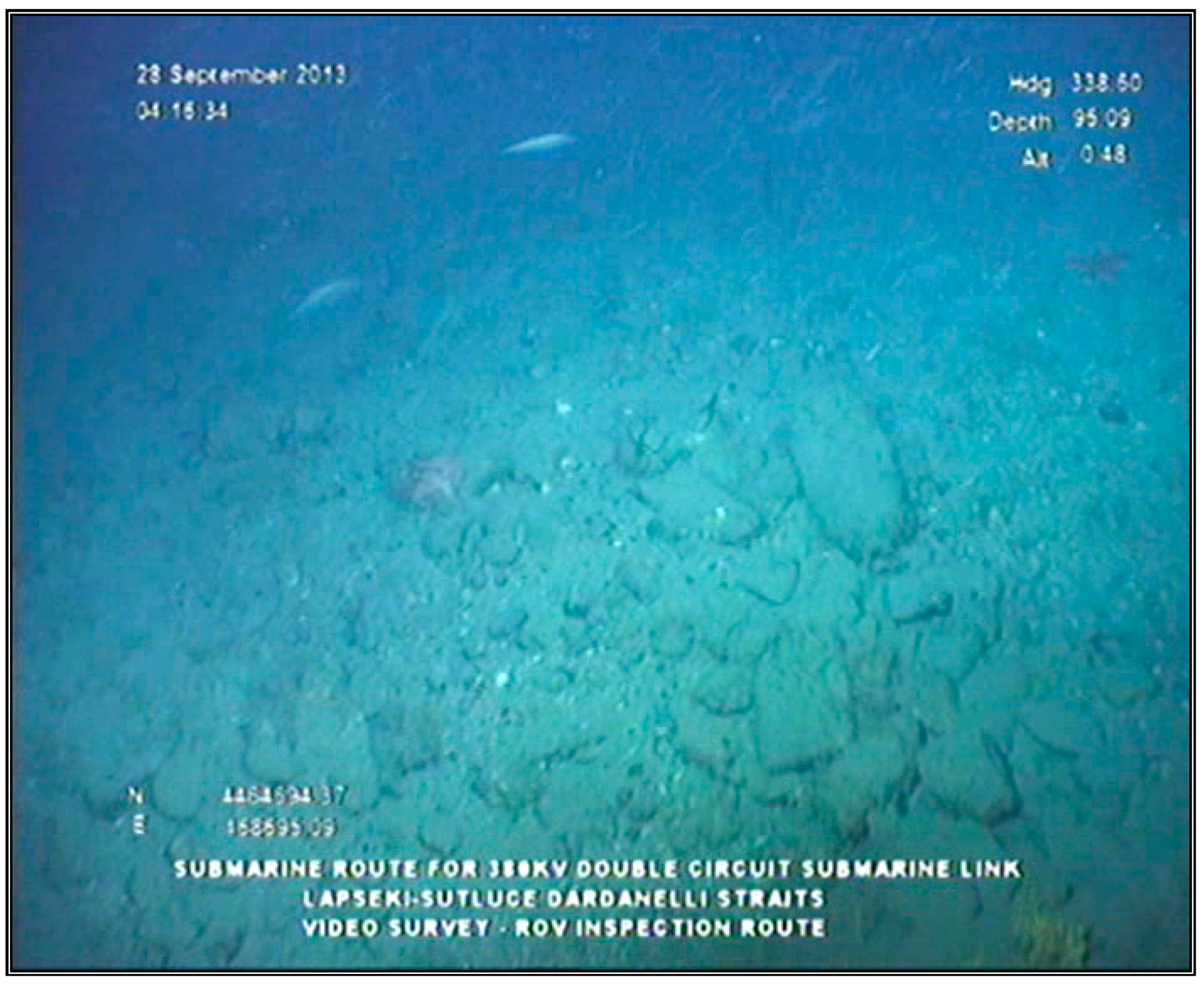
A route cable survey comprising of geophysical and geotechnical portions;
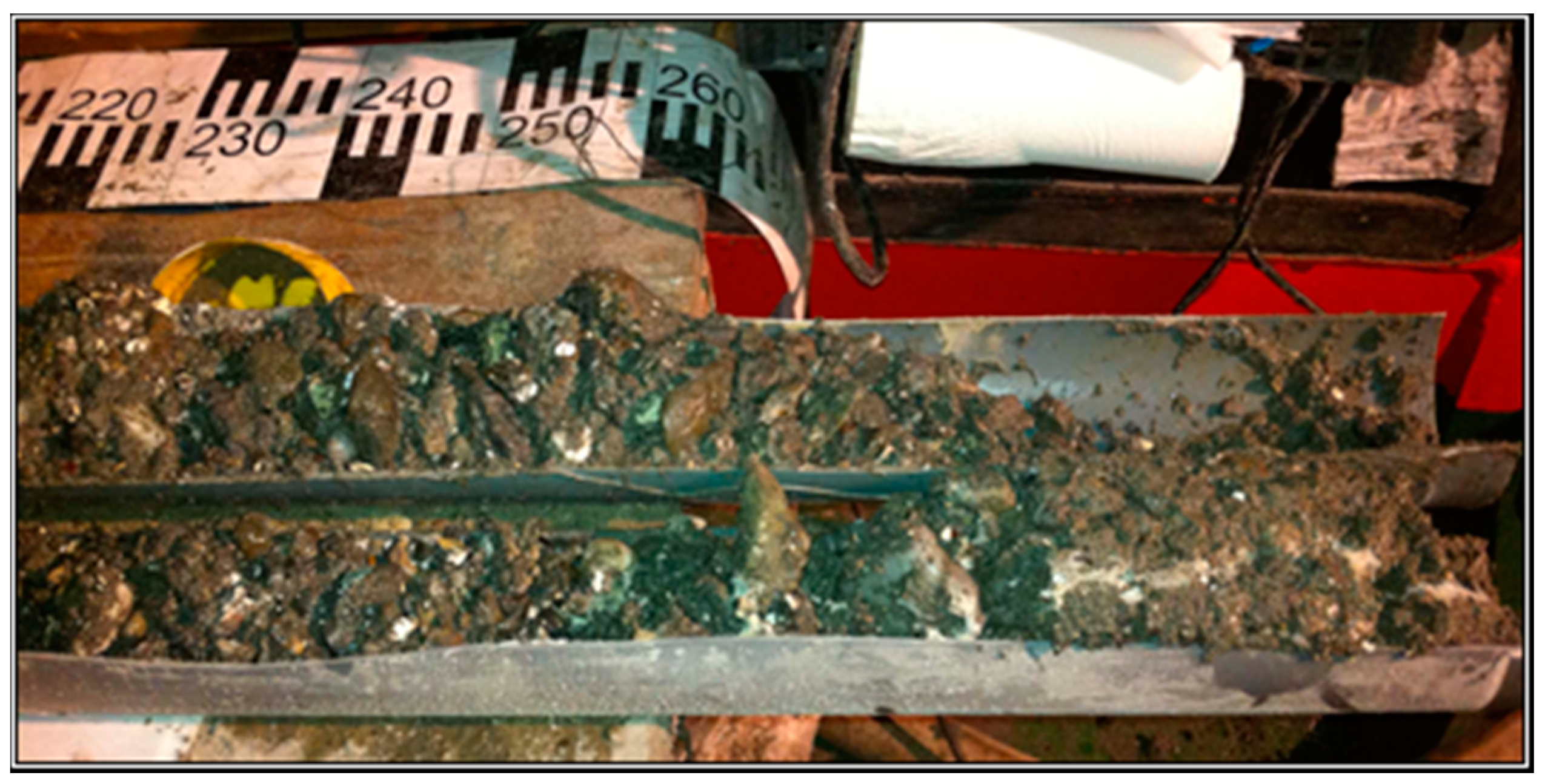
A marine survey, which could include an extraction of samples from the seabed.
The milestones are not sequential, e.g., information will have to be gathered so the route can be evaluated, but a tentative route must be chosen before a submarine survey can be done [26,27,28,29,30,31,32,33]. In any case, geotechnical investigations (meant as a direct measurement of the seabed and subsoil physical properties, e.g., by in situ sampling with laboratory analysis [29]) and ground ones (commonly including geotechnical investigations, geological studies, and geophysical surveys) must be performed before the installation begins. It is worth noting that, as wholly demonstrated by the Cigré technical brochure # 398 [26], mechanical damages by human activities (cables damaged by natural events, e.g., landslides and earthquakes are less than 9% of cable faults) are the most common cause of cable failure. The chief causes of submarine cable failure are:
Fishing activity;
Ship anchoring (chiefly in shallow water).
In general, relatively a small depth of cover is adequate for protection from fishing activities (for many years the standard burial depth was 0.6 m). Fishing activities, which pose a threat, include trawling by both beam and otter boards (there are other fishing techniques which can be dangerous for cable integrity, like shellfish dredging and stow net fishing).
It is now common practice to bury cables up to a water depth of 1 km, however, cable damage associated with fishing has been reported at depths of 1.2 km. In order to take this fact into account, the cable industry is now being asked to achieve, on some projects, burial in water depths up to 1.5 km. This is not the case of Lâpseki–Sütlüce I and II, since the maximum depth of the Dardanelles Strait reaches about 0.1 km. Therefore, burial and protection of the 13 single-core cables were mandatory.

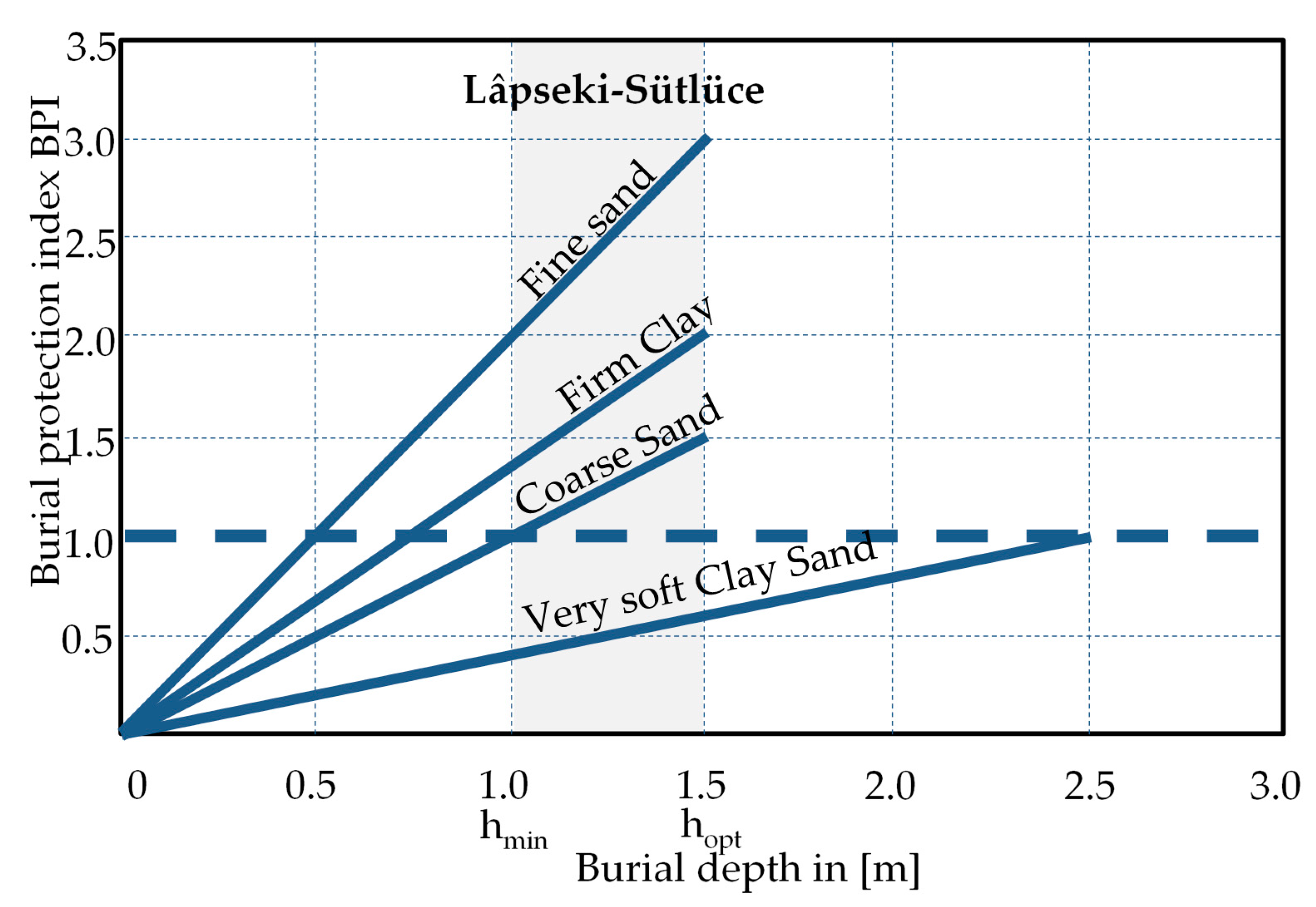
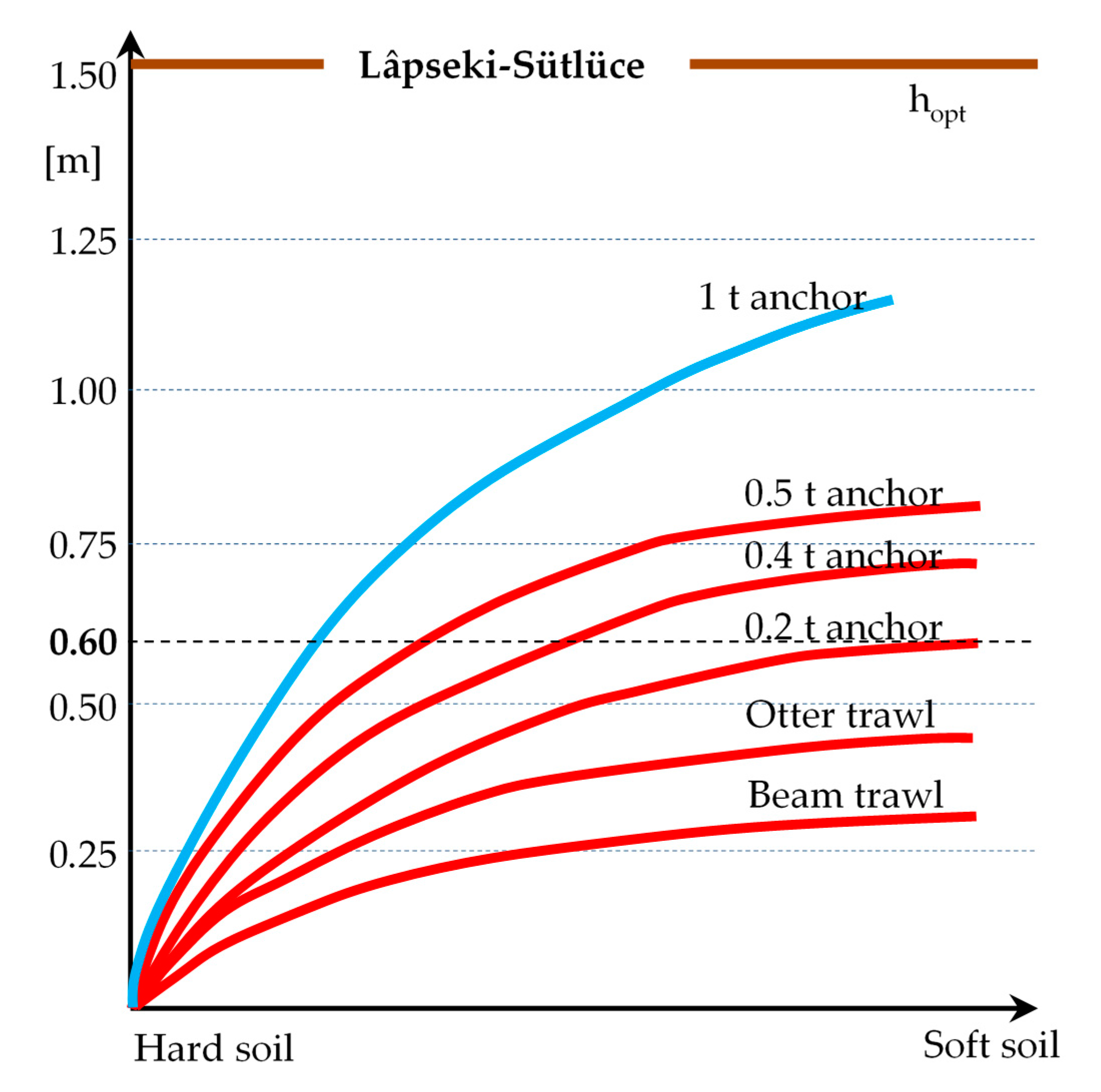
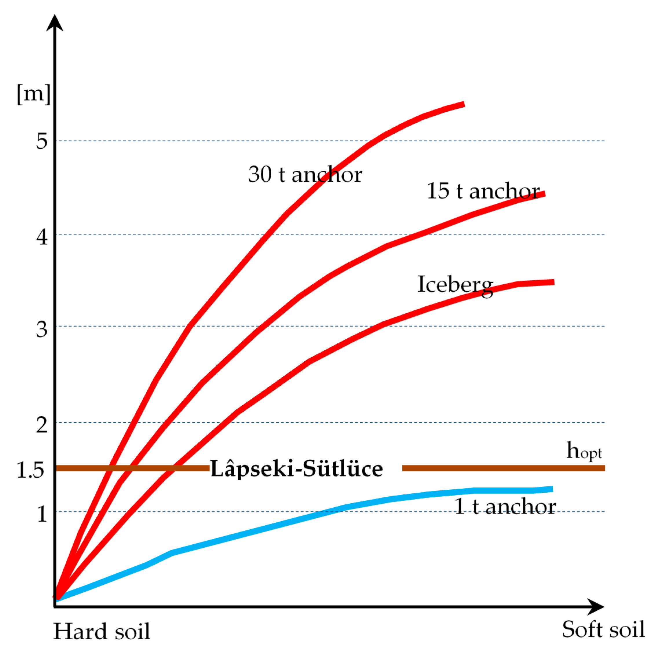
4. Assessment of Lâpseki–Sütlüce Optimal Burial Depth

The nature of the seabed soils clearly plays an important role in the depth into which anchors and fishing gear could penetrate. Figure 7 shows that, with regard to fishing gears, a cover depth equal to 0.6 m gives good guarantees, even in soft soil, to avoid cable damages [26].
With regard to the anchor penetration depth into the seabed, it depends upon both the seabed type and the anchor weight. It is rather impressive [26] that in soft seabed a 30 t anchor (see Figure 8) can penetrate 5 m inside the seabed! With regard to the Lâpseki–Sütlüce I and II installations in the Dardanelles Strait, an optimal burial depth hopt = 1.5 m (brown line in Figure 7 and Figure 8) is a very good measure to avoid anchor and fishing gear damages (with a minimum cover depth hmin = 1 m).
In order to compare this choice with other meaningful submarine installations [33], in the Oslofjord project [34], the cables were mostly buried 1 m below the seabed in order to provide general cable protection. This target was particularly important in the trawling areas. Cable and Wireless Global Marine have developed the concept of a Burial Protection Index (BPI) [29], as shown in Figure 9. This recognises the resistance of different seabed soils to penetration by anchors and fishing gears. It is based on typical soil types encountered during cable installations; however, it must be remembered that such soil mechanics is not an exact science.
The meaning of the BPI is:
BPI = 0 Assumes that the cable is surface laid;
BPI = 1 Depth of burial consistent with protecting a cable from normal fishing gear only;
BPI = 2 Depth of burial gives protection from anchors up to approximately 2 t. This may be suitable for normal fishing activity, but would not be for larger ships (e.g., large container ships, tankers);
BPI = 3 Depth of burial sufficient to protect from anchors of all but the largest ships.
It is worth noting that this approach is not general, and consequently it must be used with due care.
In any case, if the majority of the seabed in the part of Dardanelles Strait where the cables have been laid is “coarse sand with gravels and cobbles” and the depth of cover ranges between hmin = 1 m and hopt = 1.5 m, the BPI ranges between about 1.5 and 2: this should guarantee from fishing activities and anchors up to 2 t. Subsequently, where it was not possible to reach hmin, the use of further protections has been necessary.

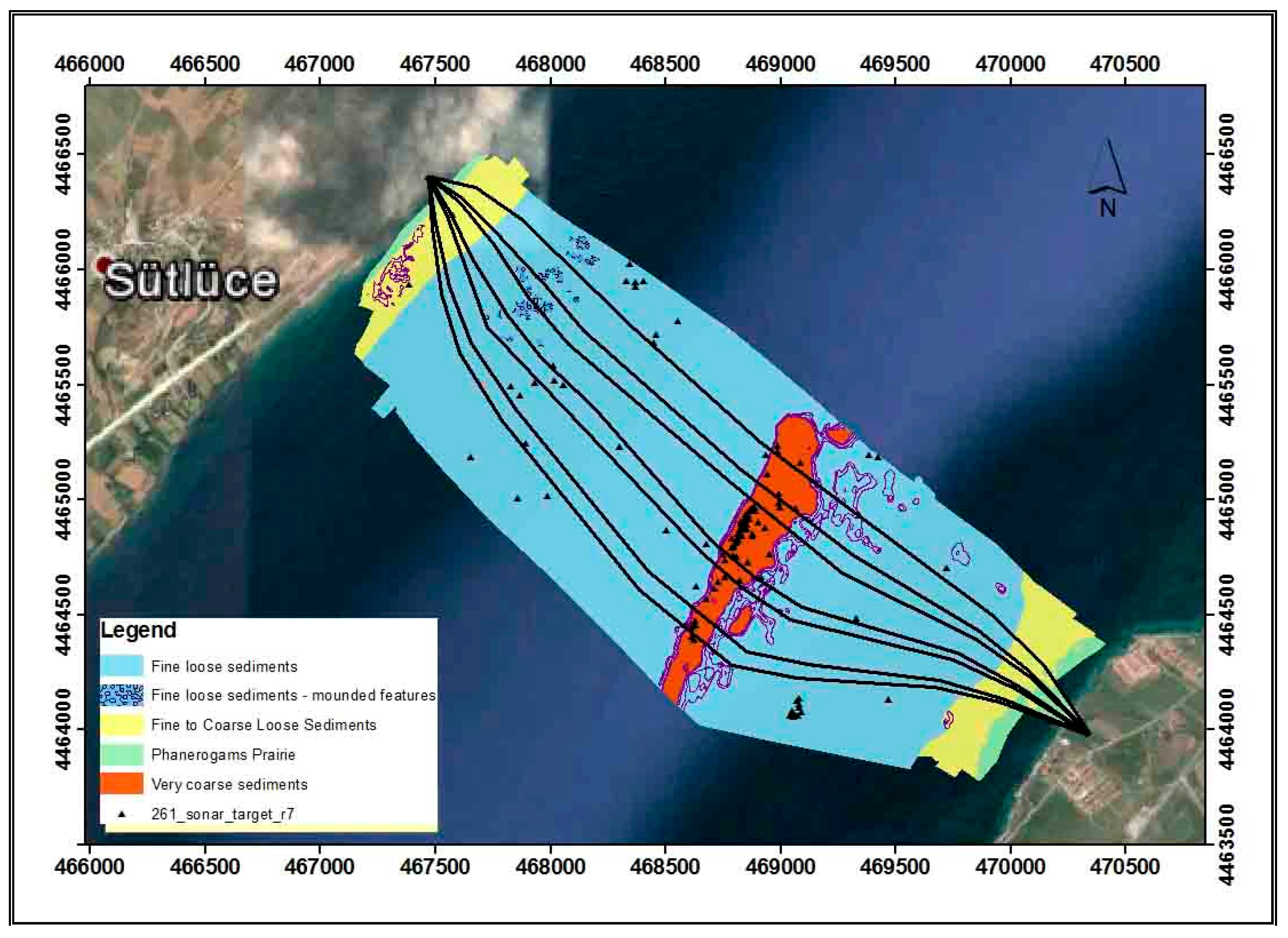
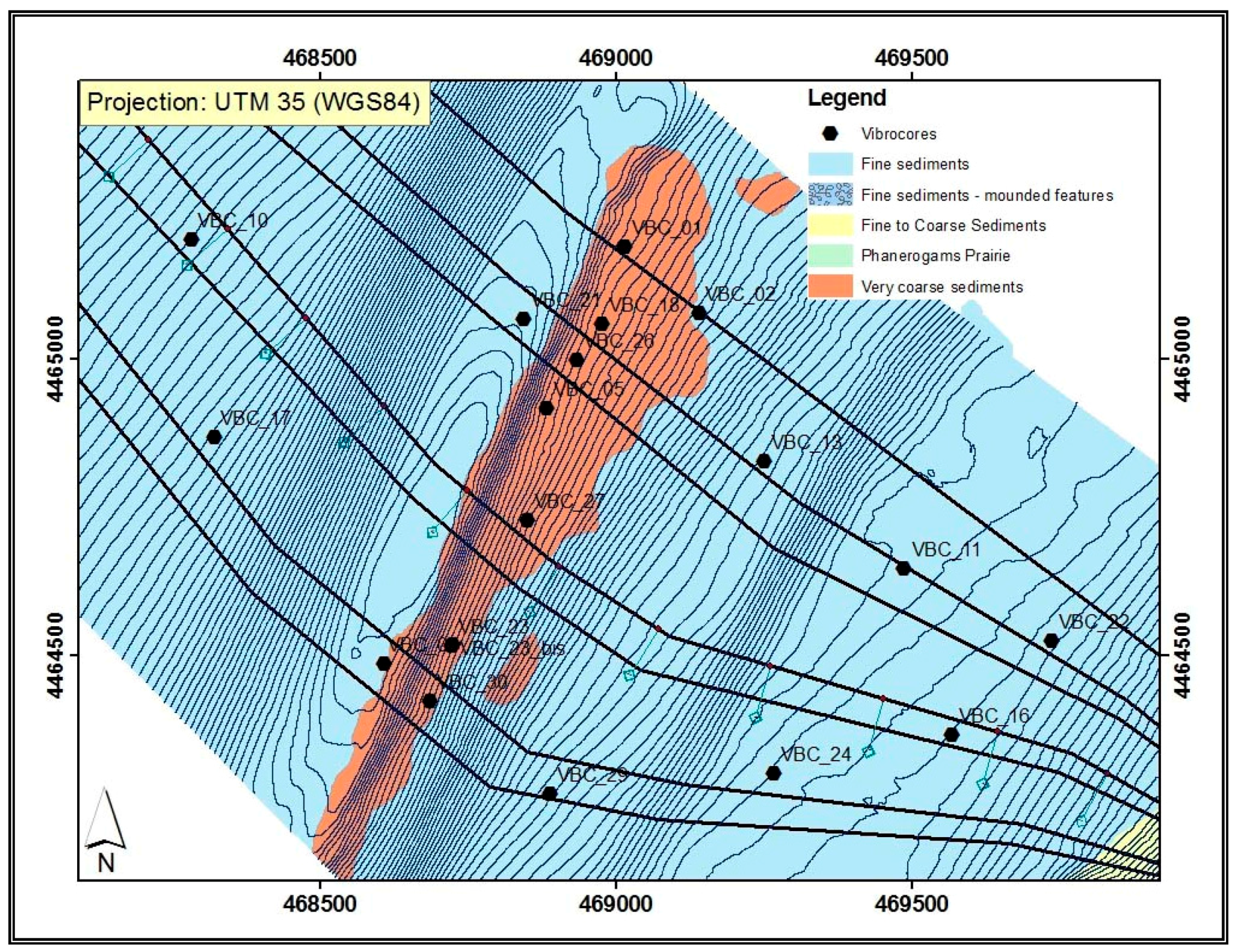
5. Verification of the Consistency of the Installation Choices of Lâpseki–Sütlüce

The marine survey conducted by Prsymian and Teiaş in order to define the final cable routes and to gather information for the burial assessment survey (BAS) was wide, detailed, and comprehensive.
The work consisted of:
A desktop study;
A topographic survey at both landings from the shoreline to the sea/land joint bay area;
A near-shore bathymetric survey;
AN offshore marine survey.
Moreover, it was decided to enlarge the marine survey to 5 additional vibrocoring and to 3.5 km offshore marine survey by a Remotely Operated Vehicle (ROV) for additional route development. Ambient conditions (like seawater temperature and salinity) ought to be taken into account. One of the route objectives is to avoid possible abrasion and damage caused by waves, tide, sea current, moving sea bottom, etc. As fully demonstrated by the Sorgente–Rizziconi submarine part [11], it is often necessary to select a cable route that may not be the shortest alternative. A distance between parallel single-core cables (or multiple three-core ones) of 100–200 m (or twice the water depth) will significantly lower the risk of damage to more than one cable due to one accident. In fact, the choice of maximum spacing in Lâpseki–Sütlüce I between the seven single-core cables (meant as the spacing between two adjacent cables) is about 250 m in correspondence to the maximum water depth of 100 m (spacing/water depth ≅ 2.5). This should reduce the risk of multiple cable damage and guarantee some available room for possible cable repair. The target is to find a seabed as smooth as possible and to avoid:
  • Rough sea bottom, which may cause free spans, abrasion, or sidewall pressure on the cable;
  • Steep slopes (less than 15–20% is recommended);
  • Natural obstacles like boulders or even human past activities as wrecks, scrap, etc;
  • Areas where waves, high water currents, high tidal range, soil movements, or ice may cause problems (it is not the case of the Lâpseki–Sütlüce submarine link);
  • Cable crossings and other cables or services nearby (as it is the case of the Lâpseki–Sütlüce submarine cables);
  • Too shallow water depth for cable laying, protection, and repair;
  • Too hard or too soft seabed;
  • Areas of existing and future marine activities like shipping channels, fishing areas.
Another merit of this detailed survey has been that the final selected routes were shorter than the reference routes with a saving in the project costs. Seabed shows a terraced morphology with few morphological steps with a slope locally greater than 15°. With regard to the burial assessment survey (BAS), the typologies of the seabed were categorized as in Table 3. It is worth noting that in the P category seabed only surgical or micro trenching was foreseen. These seabed categories are also shown in Figure 10 without reference to A, B, C, D, and P letters of Table 3.
The spare cable route encounters the D category seabed (whose definition is “veneer of loose coarse sediments, SAND/fine, GRAVEL over loose very coarse sediments, coarse GRAVEL/PEBBLES/COBBLES/possible boulders, subcropping/outcropping very coarse sediments”) for a total length of 200 m. The D soil category is visible in orange in Figure 11 and it intersects the two circuits for an almost equal length (for the northern circuit, including the spare phase, from 200 to 250 m, and for southern circuit from 110 m to 160 m). For this D category seabed, a given number of vibrocore samples were extracted from the seabed (see Figure 12). The position of the vibrocore sample with code VBC_27 is visible inside the orange zone and besides the spare cable in Figure 11.
Seabed samples collected in the D area show the occurrence of thick levels of very coarse gravel with cobbles (see Figure 12), in some cases accompanied by levels of clayey and silty sands. The gravel is, at places, outcropping, as revealed by the ROV video inspection of Figure 13. The submarine survey document reports that in D area boulders and blocks are present. The nature of the category D seabed is also confirmed by other vibrocore samples extracted in the same area.
The intersection of the two circuits in the D category seabed occurs at the crossing with the in-service (with acronym IS) telecommunication cable [35] named ITUR (see Figure 14).
The common practice of submarine cable installation considers a minimum safe distance from IS cable crossings of 100 m on both sides, while, for jetting works, this safe distance is reduced up to 20 m, if the soils and cable configuration allow. The unlucky occurrence that the category D seabed is in correspondence to the IS ITUR and Mednautilus cables rendered the cable protection extremely delicate and difficult.
Prysmian tried several jetting passes (see Figure 15 for the employed jetting machine) and used mattress covering when the cover depth was less than hmin. All the installation steps are summarized in the flowchart of Figure 16.
In the Lâpseki–Sütlüce installation, ASSOMAT II was used to perform mattress covering (see Figure 17). AssoMat II is a self-propelled autonomous installation frame.
Due to its dimensions (5.5 m × 2.9 m) along with four thrusters, AssoMat II can operate at high water depths with adverse local conditions like high currents. Its control system allows an accurate positioning of the mattresses along the protected route and a proper alignment of the sequence of mattresses.
In Lâpseki–Sütlüce, it was used when the hmin had not reached 1 m after several passes of jetting activity in the stony seabed.

6. Conclusions

This paper presents some technical features and installation characteristics of the 4 GW AC EHV submarine link under the Dardanelles Strait. This link is one of the very few EHV AC submarine cable systems with extruded insulation worldwide. Special attention was paid to the cable protection on seabed against third-party injuries due to the high maritime traffic on the Dardanelles Strait. Protection of the 400 kV cables was achieved by water jetting burial at 1.5 m in most of the routes. The 13 single-core cables have overcrossed four pre-existing in-service fibre optic cables laid on the sea bottom along the Strait. At the crossings, plastic separation sleeves were placed over the fibre optic cables, and concrete mattresses over the power cables.

Author Contributions

Roberto Benato conceived and wrote the paper. İbrahim Balanuye, Fatih Köksal, Nurhan Ozan and Ercüment Özdemirci contributed information on the installations.

Conflicts of Interest

The authors declare no conflict of interest.

References

  1. Iliceto, F.; Gubernali, A.; Yildir, K.; Durukan, Y. Special Protection System in the interface between the Turkish and ENTSO-E power systems to counteract propagation of major disturbances. In Proceedings of the 43rd International Conference on Large High Voltage Electric Systems 2010, Cigré 2010, Paris, France, 22–27 August 2010. [Google Scholar]
  2. Iliceto, F.; Gatta, F.M.; Cinieri, E.; Asan, G. TRVs across circuit breakers of series compensated lines: Status with present technology and analysis for the Turkish 420-kV grid. In Proceedings of the 1991 IEEE Power Engineering Society Transmission and Distribution Conference, Dallas, TX, USA, 22–27 September 1991. [Google Scholar]
  3. Zhang, Z.; Voloh, I.; Cardenas, J.; Antiza, I.; Iliceto, F. Inter-area oscillation detection by modern digital relays. In Proceedings of the International Conference on Advanced Power System Automation and Protection, Beijing, China, 16–20 October 2011; pp. 1396–1401. [Google Scholar]
  4. Bui-Van, Q.; Gallon, F.; Iliceto, F.; Janssen, A.L.J.; Middleton, B.; Waldron, M. Long-distance AC power transmission and shunt/series compensation overview and experiences. In Proceedings of the 41st International Conference on Large High Voltage Electric Systems 2006, Cigré 2006, Paris, France, 27 August–1 September 2006. [Google Scholar]
  5. Balanuye, I.; Köksal, F.; Ozan, N.; Özdemirci, E.; Iliceto, F.; Colla, L.; Kuljaca, N.; Kurkcu, F. 400 kV AC—2 × 1000 MW submarine cable crossing of the Dardanelles strait in Turkey. In Proceedings of the Cigré, Paris, France, 21–26 August 2016. Paper B1-310. [Google Scholar]
  6. Benato, R.; Paolucci, A. EHV AC Undergrounding Electrical Power: Performance and Planning; Series: Power Systems; Springer: Berlin/Heidelberg, Germany, 2010; Volume 47, ISBN 978-1-84882-866-7. [Google Scholar] [CrossRef]
  7. Benato, R.; Paolucci, A. Operating capability of AC EHV mixed lines with overhead and cables links. Electr. Power Syst. Res. 2008, 78, 584–594. [Google Scholar] [CrossRef]
  8. Benato, R.; Paolucci, A. Operating Capability of Long AC EHV Transmission Cables. Electr. Power Syst. Res. 2005, 75, 17–27. [Google Scholar] [CrossRef]
  9. Benato, R.; Napolitano, D. State-space model for availability assessment of EHV OHL–UGC mixed power transmission link. Electr. Power Syst. Res. 2013, 99, 45–52. [Google Scholar] [CrossRef]
  10. Benato, R. Multiconductor Analysis of Underground Power Transmission Systems: EHV AC Cables. Electr. Power Syst. Res. 2009, 79, 27–38. [Google Scholar] [CrossRef]
  11. Benato, R.; Sessa, S.D.; de Zan, R.; Guarniere, M.R.; Lavecchia, G.; Labini, P.S. Different Bonding Types of Scilla-Villafranca (Sicily-Calabria) 43 km Double-Circuit AC 380 kV Submarine-Land Cable. IEEE Trans. Ind. Appl. 2015, 51, 5050–5057. [Google Scholar] [CrossRef]
  12. Benato, R.; Lauria, S.; Gatta, F.M.; Colla, L.; Rebolini, M.; Renaud, F. Steady-State and Transient EHV AC Cable Shunt Reactive Compensation Assessment. In Proceedings of the Cigré 2010, Paris, France, 22–27 August 2010. Paper C4-109. [Google Scholar]
  13. Benato, R.; del Brenna, M.; di Mario, C.; Lorenzoni, A.; Zaccone, E. A New procedure to compare the social costs of EHV-HV overhead lines and underground XLPE cables. In Proceedings of the Cigré 2006, Paris, France, 21–26 August 2006. Paper B1-301. [Google Scholar]
  14. Colla, L.; Gatta, F.M.; Geri, A.; Lauria, S.; Maccioni, M. Steady-state operation of Very Long EHV AC Cable Lines. In Proceedings of the 2009 IEEE Bucharest Power Tech Conference, Bucharest, Romania, 28 June–2 July 2009. Paper n. 634. [Google Scholar]
  15. Benato, R.; Colla, L.; Sessa, S.D.; Marelli, M. Review of high current rating insulated cable solutions. Electr. Power Syst. Res. 2016, 133, 36–41. [Google Scholar] [CrossRef]
  16. Benato, R.; Sessa, S.D.; Guglielmi, F.; Partal, E.; Tleis, N. Ground Return Current Behaviour in High Voltage Alternating Current Insulated Cables. Energies 2014, 7, 8116–8131. [Google Scholar] [CrossRef]
  17. Lauria, S.; Gatta, F.M.; Colla, L. Shunt compensation of EHV Cables and Mixed Overhead-Cable Lines. In Proceedings of the 2007 IEEE Lausanne Power Tech Conference, Lausanne, Switzerland, 1–5 July 2007. Paper n. 562. [Google Scholar]
  18. Colla, L.; Iliceto, F.; Gatta, F.M.; Lauria, S. Design and operation of EHV transmission lines including long insulated cable and overhead sections. In Proceedings of the IEEE International Power Engineering Conference, Singapore, 29 November–2 December 2005. Paper TM-3.6J. [Google Scholar]
  19. Benato, R.; Sessa, S.D.; Guglielmi, F. Determination of Steady-State and Faulty Regimes of Overhead Lines by Means of Multiconductor Cell Analysis (MCA). Energies 2012, 5, 2771–2793. [Google Scholar] [CrossRef]
  20. Benato, R.; Sessa, S.D.; Guglielmi, F.; Partal, E.; Tleis, N. Zero sequence behaviour of a double-circuit overhead line. Electr. Power Syst. Res. 2014, 116, 419–426. [Google Scholar] [CrossRef]
  21. Benato, R.; Paolucci, A. Multiconductor cell analysis of skin effect in Milliken type cables. Electr. Power Syst. Res. 2012, 90, 99–106. [Google Scholar] [CrossRef]
  22. Matis, M. The Protection of Undersea Cables: A Global Security Threat; United States Army War College: Carlisle, PA, USA, 2012. [Google Scholar]
  23. Protection of submarine cables by placement “underground”. Electr. Eng. 1938, 57, 204–205. [CrossRef]
  24. Worzyk, T. Submarine Power Cables: Design, Installation, Repair, Environmental Aspects; Power Systems Series; Springer: Berlin/Heidelberg, Germany, 2009. [Google Scholar]
  25. Recommended Practice DNV-RP-J301 Subsea Power Cables in Shallow Water Renewable Energy Applications. February 2014. Available online: https://rules.dnvgl.com/docs/pdf/DNV/codes/docs/2014-02/RP-J301.pdf (accessed on 13 September 2016).
  26. Working Group B1.21. Cigré Technical Brochure #398: Third-Party Damage to Underground and Submarine Cables; CIGRE: Paris, France, 2009; ISBN 978-2-85873-085-8. [Google Scholar]
  27. IEEE Standards 1120: IEEE Guide for the Planning, Design, Installation, and Repair of Submarine Power Cable Systems; IEEE: New York, NY, USA, 2005; ISBN 0-7381-4473-8 SS95271.
  28. Working Group B1.43. Cigré Technical Brochure #623: Recommendations for Mechanical Testing of Submarine Cables; CIGRE: Paris, France, 2015; ISBN 978-2-85873-326-2. [Google Scholar]
  29. Department for Business Enterprise and Regulatory Reform (BERR). Review of Cabling Techniques and Environmental Effects Applicable to the Offshore Wind Farm Industry; Technical Report; BERR: London, UK, 2008. [Google Scholar]
  30. Cigré Working Group 21.06. Methods to Prevent Mechanical Damage to Submarine Cables. In Proceedings of the Cigré 1986, Paris, France, 27 August–4 September 1986. [Google Scholar]
  31. Allan, P.G. Geotechnical Aspects of Submarine Cables. In Proceedings of the IBC Conference on Subsea Geotechnics, Aberdeen, UK, 18–19 November 1998. [Google Scholar]
  32. Arnaud, U.; Bazzi, G.; Valenza, D. Advantages and disadvantages of embedment to prevent external mechanical damages to submarine cables. IEEE Trans. Power Deliv. 1990, 5, 54–57. [Google Scholar] [CrossRef]
  33. Candas, M.; Meric, O.S. The Application of Ultra High Voltage in the World. J. Power Energy Eng. 2015, 3, 453–457. [Google Scholar] [CrossRef]
  34. Oldervoll, F.; Jensen, G.; Slåtten, S.A.; Elders, J.; Kaldhussæter, E. The Olslofjord Project—The world’s first installed 420 kV submarine cable connection combining SCFF cables and XLPE cables with flexible factory joints. In Proceedings of the 9th International Conference on Insulated Cables, Jicable’15, Versailles, France, 21–25 June 2015. Paper B1.6. [Google Scholar]
  35. Da Silva, J.C.V.; de Araujo Andrade, M.; Bedia, M., Jr. Electrical Optical Power Cable. In Proceedings of the 57th International Wire & Cable Symposium, Providence, RI, USA, 9–12 November 2008; pp. 479–483. [Google Scholar]
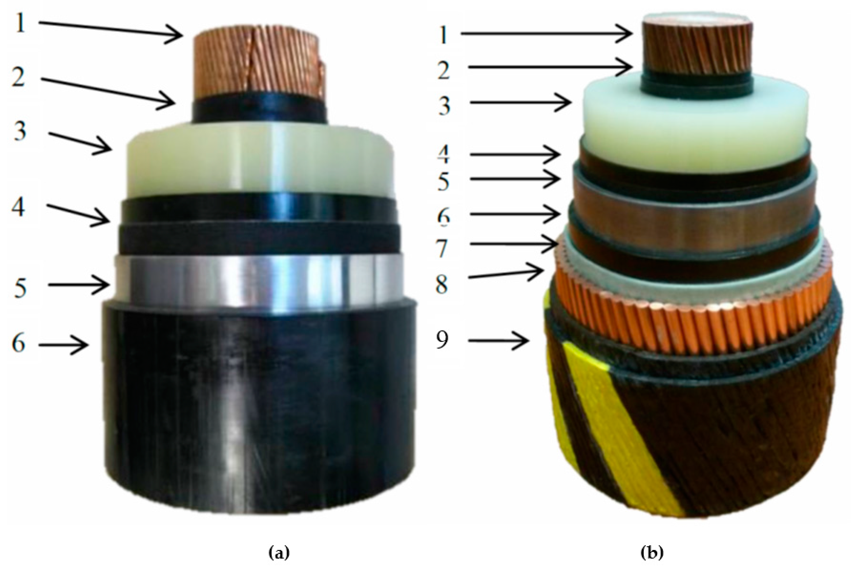
Figure 1. (a) Land Milliken-type cable; (b) Submarine armoured single-core cable [5].
Energies 11 00164 g001
Figure 2. Screen bonding arrangements for the Lâpseki–Sütlüce I cable system.
Energies 11 00164 g002
Figure 3. Single-line diagram of the Southern Marmara Sea 400 kV network (hybrid lines Gelibolu–Berkili are highlighted in red).
Energies 11 00164 g003
Figure 4. Protection of cable through burial: (a) jetting and fluidification; (b) ploughing; (c) mechanical cutting; (d) open-trench dredging.
Energies 11 00164 g004
Figure 5. Special cable protections: (a) tubular product; (b) mattress covering; (c) rock dumping.
Energies 11 00164 g005
Figure 6. Indicative burial tool suitability in different ground conditions.
Energies 11 00164 g006
Figure 7. Penetration of smaller anchors and fishing gears versus soil hardness.
Energies 11 00164 g007
Figure 8. Anchor penetration versus soil hardness.
Energies 11 00164 g008
Figure 9. Burial protection index as a function of burial depth for different seabed types [29].
Energies 11 00164 g009
Figure 10. Seabed categories encountered by the cables of Lâpseki–Sütlüce I.
Energies 11 00164 g010
Figure 11. Shallow geology model, Asia Side for Lâpseki–Sütlüce I.
Energies 11 00164 g011
Figure 12. Very coarse gravel in VBC_27 sample.
Energies 11 00164 g012
Figure 13. Very coarse gravel in the D category seabed.
Energies 11 00164 g013
Figure 14. Plan view of cable crossings due to the in-service telecommunication cables (ITUR, MEDNAUTILUS, TURMEOS, and MEDTURK).
Energies 11 00164 g014
Figure 15. Some photos of the real jetting ROV used in the Lâpseki–Sütlüce installation.
Energies 11 00164 g015
Figure 16. Flow-chart of the installation steps.
Energies 11 00164 g016
Figure 17. Assomat II used in the Lâpseki–Sütlüce installation.
Energies 11 00164 g017
Table 1. Land and submarine cable geometrical characteristics (XLPE: cross-linked polyethylene; PE: polyethylene).
Land CableSubmarine Cable
NDescriptionNominal Diameter mmNDescriptionNominal Diameter mm
1Copper conductor M-type watertight581Copper conductor with aluminium central rod watertight52.6
2Conductor Screen61.62Conductor Screen55.6
3XLPE insulation116.73XLPE insulation112.6
4Insulation Screen119.84Insulation Screen115.6
5Longitudinally Welded Al screen1245Extruded lead screen124.1
6PE outer sheath137.46PE sheath131.1
-7Bedding133.1
8Copper round wires armour144.9
9Serving153
Table 2. Comparison of Burial Techniques [25] (for the assessment see (1)).
FactorHydro JettingPloughingMechanical Cutting
Range of suitable soil conditionsMHM
Uneven bathymetryHML
High currentsLHH
Low underwater visibility, high turbidityLHL
Very shallow waterL (2)HM
Simultaneous lay and burial (SLB)MHL
Post-lay burial (PLB)HL (3)M (3)
ManoeuvrabilityHLM
Multipass capabilityHL (4)M (4)
Ability to bury bundled cablesHMM
Ability to bury loops or repair jointsM--
Safety of cable during burial operationHL (5)M
Suitability in close proximity to infrastructureHLM
Backfill qualityMHL
Environmental benignityMHM
Rate of progressMHL
Availability of suitable vesselsHM (6)H
Mobilisation layout flexibilityHLM
Ease of catenary/tow line managementHMH
(1) Assessment: H = High/more favourable, M = Medium/neutral, L = Low/less favourable, - = not applicable; (2) Requires water supply. Typical minimum water depths are 5 to 10 m for ROV based systems; (3) Requires subsea loading of cable if start and end points are offshore; (4) Single pass only, except for pre-lay trenching operations; (5) A cable manufacturer may recommend not using ploughing as a burial technique; (6) Large bollard pull required. Due to size and weight of plough, generally launched over stern, not side.
Table 3. Seabed categories encountered in the cable route.
CategoryCover Depth (m)Seabed ConditionsProtection
A>1.50fine sediments (soft clay/silt) and/or coarse sediments (loose to dense sand) with thickness >1.65 mjetting
B1.00–1.50fine sediments (soft to firm clay/silt) and/or coarse sediments (loose to dense sand/fine gravel) with thickness 1.15–1.65 m
C0.75–1.00fine sediments (soft to firm clay/silt) and/or coarse sediments (loose to dense sand/fine gravel) with thickness 0.90–1.15 m
DvariableSubcropping/outcropping very coarse sediments (loose gravel/pebbles/cobbles/possible boulders)jetting attempt + other protection
Papprox. 0.50Cymodocea nodosa prairiemicrotrenching

