1. Introduction
The human exposure to electro-magnetic (EM) fields and its consequences on health have been addressed in depth in several scientific research works. The potential health hazards caused by prolonged exposures to EM fields at extremely low frequencies (ELFs) are statistically characterized. Research activities focus on the commonly used industrial frequency of 50–60 Hz, since this value is the worldwide standard for electrical power production, transmission and consumption, with exception of direct current (DC) systems (e.g., a part of the electrical traction, long transmission lines, etc.) and specific drives or applications [
1,
2,
3]. However, the high number of results, obtained from epidemiological studies and statistical evaluations, bring one to very contrasting conclusions. A significant lack of homogeneity among obtained conclusions is appreciable, ranging from the hypothesis of zero risk to the evident danger, e.g., the quite strict correlation between the magnetic field exposure and cases of leukemia and cancer [
4,
5,
6]. Physic laws establish that ELF EM fields are ‘non-ionizing’ radiations due to their extremely low energy density, consequently they are not able to break bonds between molecules and thus to cause DNA alterations. However, induced currents on human tissues may increase the cellular temperature, acting as catalysts in particular biological processes, with indirect but not negligible effects on health.
The public opinion is increasingly focusing its attention on these themes and consequently national and international authorities have regulated citizens’ exposure to industrial frequency EM fields by introducing specific rules and constraints [
7]. Furthermore, the International Commission on Non-Ionizing Radiation Protection (ICNIRP) has issued guidelines for the protection of citizens and workers in terms of admitted and safe exposure to EM fields [
8]. The European Commission, according to these suggestions, issued the ‘Council Recommendation’ on 12 July 1999 [
9]. Not knowing in detail which are the effects of EM fields on the human body (considering both short-term effects and long-term consequences), the exposure constraints are generally based on a precautionary principle [
10], which involves extremely reduced field limits if compared to the field values able to generate immediately visible effects (e.g., nervous tissue stimulation). In several countries, these recommendations have been transformed into binding national laws which regulate the planning, the design and the use of transmission overhead lines, directly impacting on the exploitation of areas under or close to the electrical infrastructures. Consequently: (i) existing transmission systems may have to limit the circulating current under admitted thresholds to satisfy exposure limits (i.e., power lines are required to permanently work at reduced loading compared to their theoretical current capacity, directly correlated to their installation cost); and (ii) new buildings, constructions or other extensive uses of areas close to the overhead line are forbidden within a defined distance from the line axis.
Partially replacing or rebuilding a high voltage (HV) power line, in the case it results not compliant with international or local regulations, may be extremely expensive. Indeed, several techniques have been developed for the magnetic induction field mitigation, the majority of them with huge impacts on the mechanical structure and high costs. The most commonly studied and applied proposals are complex or largely impacting actions, for example: (i) increasing conductors height from ground-level, with consequent increase of the visual impact of the infrastructure; (ii) installing active shielding loops [
11]; (iii) introducing passive loops [
12,
13]; (iv) splitting the conductors; and (v) rearranging the line wires. Rarely, less invasive methods are discussed [
14].
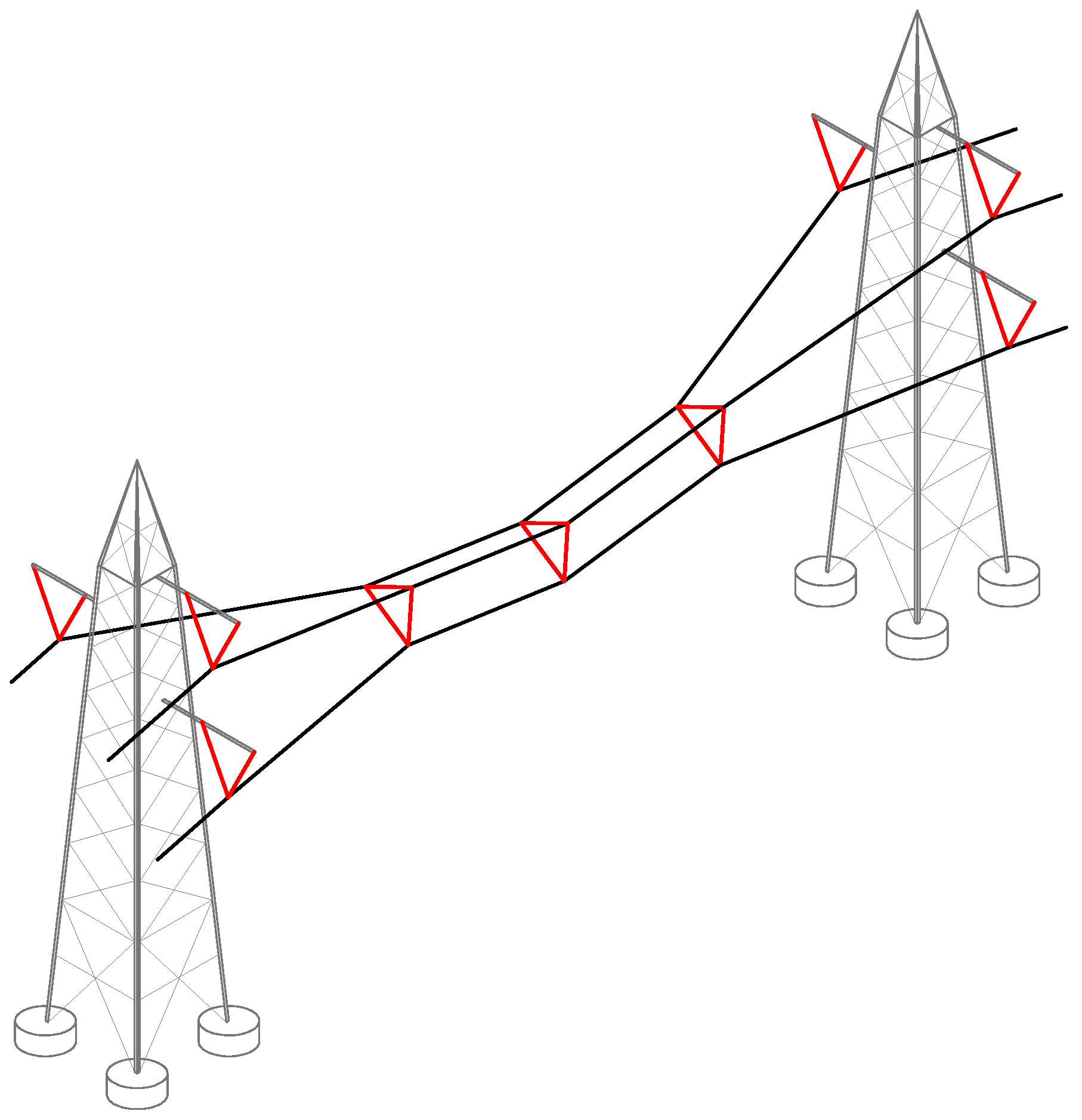
In this paper, the authors investigate and discuss an effective procedure for the magnetic field passive mitigation. The proposed solution synthetically consists in the installation, along the span, of one or more compactors. A compactor is a simple mechanical system composed by three long rod insulators, disposed to form an equilateral triangle, with each side connected between two phase conductors, as briefly represented in
Figure 1. Reducing the phase-to-phase distance, an increase of the electric field close to the line conductors is expected, however both radio and audible noises are accurately predictable through [
15].
Considering an ideal line making use of the same tower type at both the span end points, in the case several compactors are added along the span, they are generally expected to be placed symmetrically as regards to the span central point. The installation simplicity and the reduction of the overall action cost are key drivers of the developed criterion, so it can be easily applied to both existing transmission/distribution lines and future installations. On the other hand, reducing the distance between phase conductors along the span would increase the risk of deaths of big birds when they perch on line wires. Consequently, the environmental impact of the proposed passive method for reducing the magnetic field has to be analyzed taking into account the local characteristics (e.g., height above sea level, wildlife, bird migration trajectories, etc.). In addition, live-line maintenance practices along the span are required to be reviewed due to the reduction of clearance caused by the compactors installation. However, it should be noted that the discussed solution is primarily focused on sub-transmission lines, i.e., rated voltage of 132–150 kV, for which live-line activities are limited. Even if the method is directly extendable to overhead transmission lines with upper rated voltages, they are rarely realized close to build-up areas (where magnetic field mitigating actions would be required).
In particular, one or more compactors are installed along the line span to approach the phase conductors in the area in which they are closest to the ground level and indirectly to reduce the span sag. Both these effects contribute to the magnetic field containment, both at ground level and on higher plans. As introduced in [
16,
17], Equation (1) approximately shows how the magnetic induction vector RMS value
B (T) is directly related with the phase-to-phase distance
d (m). Parameter
µ (H/m) is the magnetic permeability (referring to air in case of bare wire overhead lines),
C (dimensionless) is a coefficient depending on the layout of conductors (aligned or triangular posed) as defined in
Table 1,
r (m) is the distance of the observing point from the line barycenter and
I (A) is the line current RMS value (considering a balanced three-phase system):
The authors have developed a 3-dimensional representation of the layout of phase conductors along a single span to validate the introduced solution, i.e., to verify: (i) the magnetic field obtained at different planes; (ii) the physical distance between bare wire conductors in each point of the line; and (iii) the mechanical stresses on the overall infrastructure (i.e., insulators composing the compactors, conductors, towers and tower insulators). The proposed procedure can be directly applicable in the case the distances between conductors and the tower configuration are known and fixed (e.g., use of V-insulators or towers in compact configuration). However, the approach can be easily extended to a general line layout, if a global set of data is available (e.g., the line path on adjacent spans). In addition, the procedure could be easily generalized for considering bundle configurations (e.g., duplex and triplex), even if they are not modelled in this paper since they are rarely adopted in sub-transmission networks (132–150 kV).
In the paper,
Section 2 reports the system mechanical modelling, which consists in the mathematical characterization computing the real layout, in the three-dimensional domain, of each of the three phase conductors, considering the constraints involved by the compactors presence. In
Section 3, the procedure for evaluating the reduction of the magnetic induction field is reported. Results obtained for a real context and some parametric analyses are reported and discussed in
Section 4 to validate the approach, whereas
Section 5 summarizes the most relevant conclusions.
2. Cable Modelling
The base theory representing the mathematical model able to define the equilibrium position of a system of three independent conductors along a span (single wire modelling, i.e., without compactors) is firstly reported. Then, the procedure developed by the authors with the aim of modelling the complete system with one or more compactors is deeply described.
2.1. Base Theory
In the literature, the three-dimensional modelling of cables systems, without mutual mechanical influences, has been widely explored, in particular considering its high non-linear behavior: in [
18,
19,
20] the problem formulation is presented, while a dynamic analysis is reported in [
21].
In order to preserve the procedure generality, the paper considers generic metallic wires, perfectly flexible, elastic, subjected to thermal expansion according to their temperature, loaded with both uniformly distributed stresses (e.g., the wire weight) and concentrated stresses (e.g., mechanical connections to tower, compactors along the span). Wire data are available in the undeformed configuration (wires at a known temperature and not installed, i.e., not subjected to mechanical tension), whereas the wire layout computation has to consider all the aspects affecting the deformation of the wire (i.e., both the elastic response to mechanical tension and the thermal expansion).
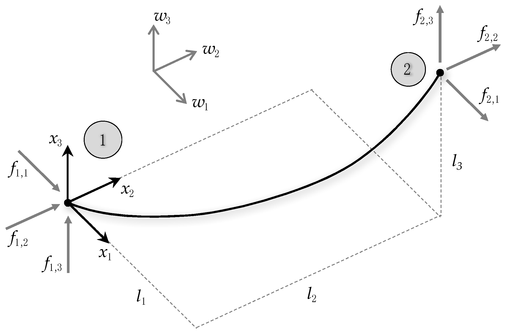
For a single cable modelling, a wire suspended between two points 1 and 2 with Cartesian coordinates (0, 0, 0) and (
l1,
l2,
l3) is considered, as depicted in
Figure 2 [
22]. The distributed load
w (expressed in (N/m) according to the IS) is decomposed along the three axes through its components
w1,
w2,
w3 (N/m). The cable equilibrium in a three-dimensional space is defined for each point through the dedicated Equation (2) [
22], where: (i)
s (m) and
p (m) are the Lagrangian coordinates of the undeformed and deformed wire, respectively (distance from point 1); (ii)
T(
s) (N) is the cable tension at the Lagrangian coordinate
s; (iii)
x1,
x2,
x3 (m) are 3D coordinates; and iv)
f1,1,
f1,2,
f1,3 (N) the projections of the external forces on node 1 (in the studied configuration, the tower forces):
Considering the cable elastic modulus
E (N/m
2), the cross-sectional area
A (m
2), the linear thermal expansion coefficient
α (1/K) and the cable over-temperature Δ
T (K) with respect to the standard value
T0 (K), a generic formulation for the 3D position of each point of the cable is given by Equation (3) [
22]:
A discrete analysis is needed to obtain the cable modelling solution. In addition, this type of procedure with finite elements allows the introduction of concentrated forces, necessary for the correct development of this work. A simple algorithm for the cable modelling and its solutions is detailed in the cited paper. An iterative procedure evaluates: (i) the forces f1,1, f1,2, f1,3 that satisfy the condition , where L (m) is the line length; and (ii) the wire 3D disposition.
2.2. Improved Procedure
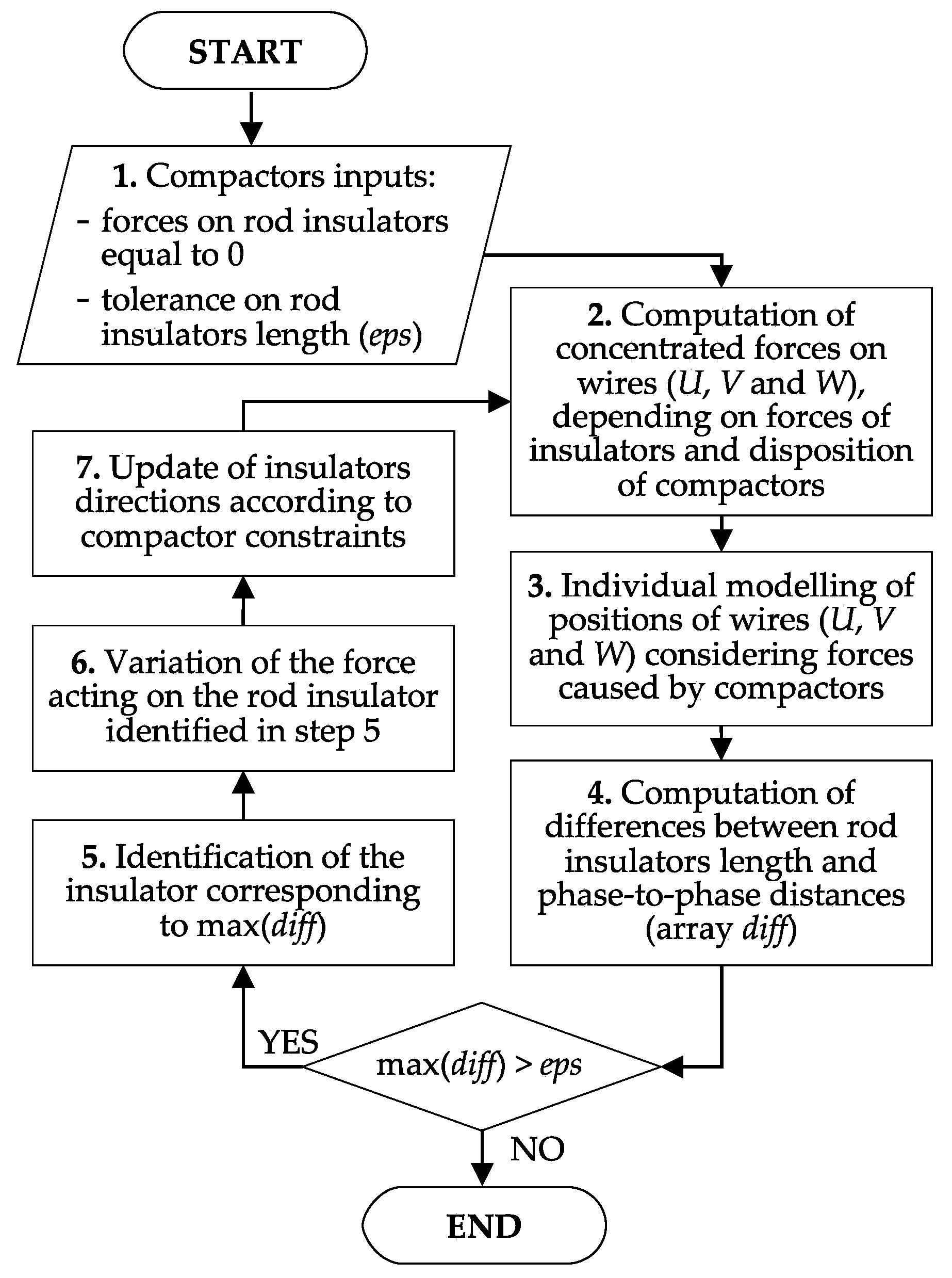
In this paper, the authors propose an improvement of the procedure to achieve the 3D modelling of a three-conductors overhead power line in which compactors are installed along the span, with their vertices connected to the three phases (named as U, V and W). The developed procedure evaluates this type of structure through an iterative method since an analytic solution is not possible. Furthermore, a global analysis of the overall problem has to be considered, since the spatial configuration of each cable along the span is closely related to the others due to the presence of compactors.
According to the base theory, the insertion of rigid elements between two conductors in a specific point of the span (imposing the phase-to-phase distance equal to the rod insulator length) is difficult to be directly implementable in the mathematical formulation of the overall problem. Conversely, the evaluation of the conductors distance trend along the span can be obtained a posteriori in two steps: (i) imposing the forces exerted by the insulators (in module and direction); and (ii) computing the resulting layout of each phase conductor through the single wire modelling (where stresses introduced by compactors are applied as concentrated loads). For this reason, the proposed resolution strategy basically consists in an iterative algorithm that modifies step by step insulators angles and applied forces, following a defined criterion. The entire system, including tower insulators, phase conductors and added compactors, is solved through the iterative procedure briefly depicted in the flow chart of
Figure 3. Distances between conductors along the span are computed depending on the applied stresses, both distributed (e.g., wire weight and wind horizontal stress) and concentrated (i.e., applied by tower insulators and rod insulators composing the compactors). The procedure is repeated until the distances between the phase conductors match with insulators dimensions (lengths) in the points where compactors are installed.
In detail, the overhead line solution without compactors is the initial configuration (insulator forces equal to 0 N, step 1). At each iteration, the numerical analysis updates the position of the suspended system in step 3, imposing the concentrated stresses (evaluated in step 2) which result from the insulators forces and directions (evaluated in step 7 with exception for the first iteration). If the highest among the differences between each phase-to-phase distance (in the points where compactors are installed) and the corresponding rod insulator length is lower than an admitted tolerance eps (m), the process ends. The convergence parameter eps represents the maximum acceptable tolerance of the solver. If the convergence condition is not satisfied, the procedure continues by identifying the rod insulator for which the convergence condition is the most far to be respected (step 5). Then, exclusively the force acting on the identified insulator is varied basing on the bisection method (step 6).
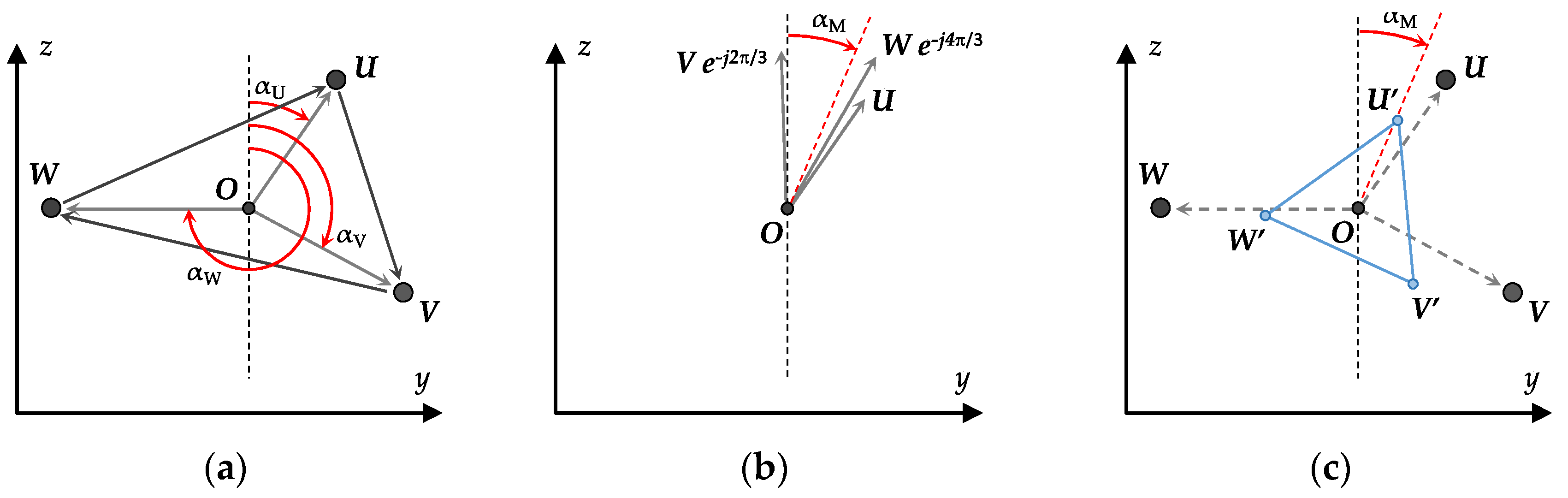
Once step 6 is concluded (i.e., the force applied to the insulator identified in step 5 is varied), the new forces set is updated in terms of direction (step 7) according to the criterion described in the following. The proposed approach is required to obtain the algorithm convergence to the desired output, since applying more intuitive procedures (e.g., obtaining forces directions directly from wires position at each computation step) could be ineffective (in a large number of cases, forces modules diverge to infinite and, consequently, a solution is not reachable). Conversely, in this paper, the three vertices of the triangle formed by the rod insulators end points (positions in which the compactor is connected to the overhead conductors) are jointly considered. Referring to
Figure 4, the directions of forces exerted by the rod insulators composing the compactors are updated according to the method here described (the highest phase is called
U, whereas the others are named
V and
W in clockwise order, respectively):
The coordinates of the compactor triangle barycenter (point O) are computed depending on the wires position obtained at step 3;
Considering a vertical plane
yz orthogonally crossing the transmission line (
Figure 4a), the phases angles
αU,
αV and
αW (rad) are obtained as the intersection between the vertical line passing through the point
O (dashed line) and segments
OU,
OV and
OW (
OU,
OV and
OW connect the point
O with the phases positions
U,
V and
W, respectively). Angles are evaluated in clockwise direction. In this step, a negligible approximation is introduced considering as vertical a plane orthogonal to the wires, in particular for the compactors placed far from the central point of the span;
Considering the compactor as an equilateral triangle, taking
αU as reference angle, values
αV' and
αW' are defined as in Equation (4) and the average value
αM is computed by Equation (5) as graphically explained in
Figure 4b:
In correspondence with the triangle defined by the conductors positions computed at the present computation step, an ideal equilateral triangle is created with these rules (
Figure 4c): (i) the ideal triangle has its barycenter in the point
O (coordinates in the 3D domain); (ii) the ideal triangle dimensions are linked to insulators length
D (m); and (iii) the ideal triangle position on the vertical plan is obtained by rotating the computed triangle of
αM. With these assumptions and considering the geometrical properties of equilateral triangles, coordinates of vertices are obtainable as in Equation (6), where vectors are reported with bold style and
R (m) is equal to the rod insulator length
D divided by
. Directions of the three insulator forces are consequently obtained applying Equation (7):
Forces acting on insulators are introduced into the three wires analysis, considering the ideal triangle geometry.
The 3D layout of each phase conductor and forces acting on each insulator (considering both tower insulators and compactors) are the results of the developed procedure. The authors did not meet difficulties in the iterative calculation convergence if realistic parameters are introduced as input.
It should be noted that, in the proposed approach, the end points of wires are supposed to be fixed. This assumption is verified in the case towers are realized with the compact construction, which is the configuration able to reduce as much as possible the magnetic field without using compactors. However, the procedure is easily extendable to the general case in which, as a consequence of the installation of compactors along a line span, conductors end points are free to lightly move along the line axis (e.g., towers with “V” insulators). In this tower configuration, if compactors are installed on a single span, they lightly reduce the span length and modify the forces acting on tower insulators (wires-to-tower connections). In the generic configuration, the wire end points shifting on the longitudinal direction is evaluable by analyzing consecutive line spans and comparing forces acting on towers. In general, more mechanical information about both transmission line (length, path, etc.) and tower types are required to obtain a complete generalization of the approach.
2.3. Available Outputs
The described algorithm is able to compute the layout of conductors composing the 3-phase system, with and without compactors along the line, aiming to compare the traditional line configuration with the proposed magnetic field passive mitigation method. Furthermore, obtained results allow to verify the technical feasibility of the introduced solution, e.g., by relating insulator stresses with components datasheet (maximum traction/compression forces admitted by the insulators composing each compactor). In detail, outcomes obtainable from the computation algorithm, with or without compactors, are composed by:
position of each point of each phase conductor according to the discretization distance;
real distance between pairs of conductors along the span;
line maximum sag;
line minimum ground clearance;
mechanical tension acting on each point of each phase conductor;
for each phase, rest wire length and real wire length considering deformation;
maximum mechanical tension for each phase wire (U, V, W), to be compared with both mechanical failure load (depending on the cross-sectional area A) and safety coefficients;
forces on wires exerted by towers;
forces applied to insulators, to be compared with their failure load (both in terms of compression and traction stresses);
laying parameter of each phase, defined as the ratio between the horizontal tension and the wire linear weight.
The set of output parameters is enough to verify the correct design of the system and the mechanical compliance of each component in the case compactors are added to existing lines.
3. Magnetic Field Computation
The second step of the herein illustrated procedure is the magnetic field computation in the space around the overhead line, with a specific focus at 1 m above the ground level (height normally used for human exposure assessments). In this way, benefits obtained by the compactors installation are directly evaluable by comparing the ex-ante and the ex-post configurations.
Different procedures able to estimate the magnetic field generated by an overhead line are available in the literature. A two-dimensional calculation would be faster [
23], but the complexity of the system configuration requires a more detailed 3D analysis, taking into account the particular layout of conductors after the compactors installation (markedly not parallel in the compacted configuration). A procedure based on a discrete approximation of the Biot-Savart law, exploiting a polygonal approximation for the conductor catenary is presented in [
24]. Other authors proposed to use numerical calculations as the Charge Simulation Method and the Finite Elements Method [
25]. Further computation approaches are discussed in [
26]. A software environment for the 3D prediction of field from generic complex configurations of conductors is presented in [
27].
In this work, the 3D computation of the magnetic induction field generated by
n arbitrarily located conductors is developed in accordance with the Biot-Savart law summarized in (8), where
dB is the infinitesimal contribution to the magnetic induction flux density in the spatial point
p(
xp,
yp,
zp) caused by the current
I flowing on an infinitesimal portion of wire
dl,
r is the vector representing the distance between
dl and
p, and
r is the module of
r:
The total magnetic induction flux density in
p, generated by a wire represented and parameterized through a generic curve
γ, is thus given by Equation (9):
Referring to an overhead power line, for computational reasons, each
k-th conductor is discretized into a finite number
m of connected elements Δ
lk,i (
i = 1, …,
m), in which the time-periodical current
, represented as a phasor in Equation (10) with RMS value
Ik and phase
ϕk, flows [
27]. The element
rk,i is the vector connecting the observation point
p and the
i-th element of the
k-th conductor Δ
lk,i, whereas
rk,i is its magnitude. Thus, Equation (9) can be translated into Equation (11) for evaluating
, i.e., the magnetic induction contribution of the
k-th conductor in
p:
In the case of
n conductors, the overall magnetic induction flux density vector
is given by the sum of contributions of all the current-carrying conductors, as in Equation (12), where
,
and
are the three Cartesian components of the magnetic flux density [
28]:
Thus, the magnetic induction RMS value is conventionally computed as in Equation (13) [
17,
27]:
Ground level magnetic fields may be affected by induced earth return currents. The effect of these currents can be suitably accounted for by applying the well-known Carson’s theory. It should be noted, however, that in the region near the conductors (let’s say within the right-of-way) the source currents dominate. In this region the contribution of the image currents may be neglected [
29], thus reducing the computational effort.
4. Simulation Results
The proposed procedure is applied to a real case study in which the ground level magnetic field is not compliant with legislation constraints despite the tower height has been sensibly increased and the tower has been converted into the compacted configuration, i.e., the tower type which minimizes the magnetic field without using compactors. To avoid a sensible reduction of the admitted power flowing through the overhead line, the installation of compactors has been investigated. Mechanical stresses and field mitigation have to be jointly investigated ex-ante to define both the side length of triangular compactors and their optimal placement along the span.
Both the above presented steps of the overall procedure (physically modelling the three-phase line layout with compactors and computing the magnetic field distribution), have been implemented in MATLAB® code (version R2015b). As shown and discussed below, results confirm a dramatic field reduction in the span center (where the field is maximum in traditional overhead lines), generally greater than 50%. In relative terms, higher field reductions are obtainable considering traditional towers (not adopting a compacted configuration).
4.1. Base Configuration
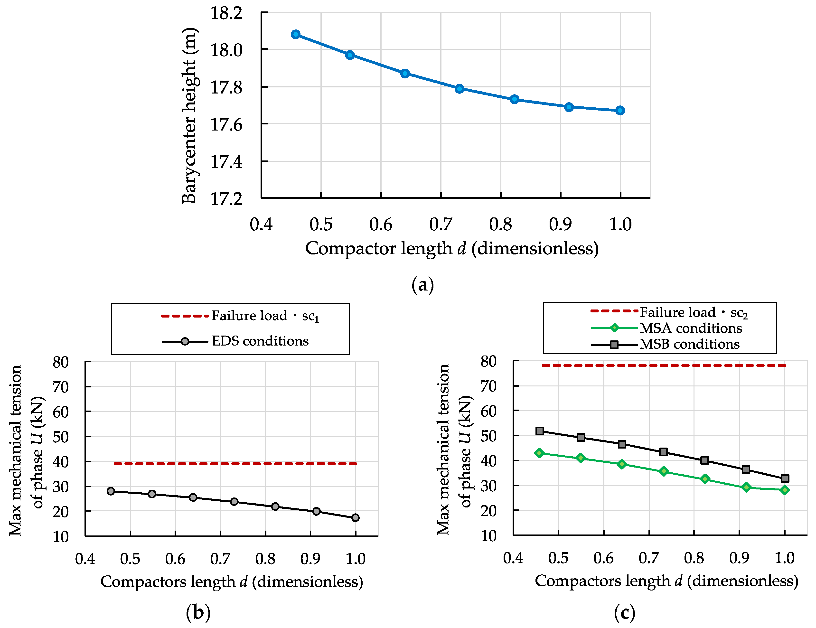
The base configuration consists of a 132 kV overhead line with span of length 200 m, undeformed conductor length of 200.20 m at 0 °C and wires end points with coordinates U (0, 2.6, 24.7/200, 2.6, 24.7), V (0, 2.8, 20/200, 2.8, 20), W (0, −0.8, 22.2/200, −0.8, 22.2). The line current RMS value is equal to 300 A, with balanced load.
For designing the compactors, it should be noted that international and national technical rules, e.g., [
30] for the Italian context, impose the minimum distance between phase conductors as a function of the line sag, the type and dimension of insulators, and the line rated voltage (considering also the presence of earthed structures, such as line towers). In the proposed method, considering that wires are approached only along the span, the minimum distance between phase conductors is 1.82 m according to [
30]. Thus, the length of rod insulators composing the compactors are prudently set not shorter than 2 m.
Wire main characteristics are reported in
Table 2. Three compactors have been located at 1/3, 1/2 and 2/3 of the line length since this solution represents a good trade-off between the mitigation effect and the admitted increases of mechanical stresses, as detailed in the following. The installation of more than three compactors seems to be not justified in terms of magnetic field reduction, whereas the influence of both the compactors size and their location along the span is investigated in the sensitivity analysis. Both the magnetic induction field mitigation and additional mechanical stresses are investigated for assessing the optimized compactors configuration.
Three environmental conditions are considered for testing the overhead system, according to present technical rules:
Everyday stress (EDS) conditions: temperature 15 °C, no ice on phase conductors, no wind. In this configuration, the sole distributed stress is the wire weight and the maximum mechanical tension applied to phase conductors has not to overpass the breaking tension of wires, multiplied by a security coefficient
sc1 equal to 0.25 [
30];
Conditions of maximum stress for the climate zone A (MSA): temperature −5 °C, no ice on phase conductors, wind blowing at speed 130 km/h (36.11 m/s). In this configuration, the horizontal stress due to the wind is added to the wire weight. Considering the wire data reported in
Table 2 and prudently assuming an air density of 1.25 kg/m
2, the wind stress is equal to 21.94 N/m. In this particular operating condition, considering its probability on an annual basis, the maximum mechanical tension applied to phase conductors has not to overpass the breaking tension of wires, multiplied by a security coefficient
sc2 equal to 0.50 [
30];
Conditions of maximum stress for the climate zone B (MSB): temperature −20 °C, layer of ice covering phase conductors (thickness 12 mm, unit mass 900 kg/m
3), wind blowing at 65 km/h (18.06 m/s). In this working condition, the vertical distributes stress is increased by the ice weight (10.38 N/m) whereas the horizontal action of the wind is equal to 12.95 N/m (considering that the ice layer increases the overall diameter of the phase conductor). The same security coefficient
sc2 is applied in the mechanical design of the overhead structure [
30].
Considering the EDS conditions,
Table 3 reports the representative comparison, in terms of mechanical characteristics and stresses, between the ex-ante line configuration (without compactors) and the investigated solution in which 3 compactors with side length 2 m have been added. The same results are reported in
Table 4 for the MSB conditions, which are generally more burdensome than the MSA conditions.
Results reported in
Table 3 and
Table 4 confirm that applying the compactors on existing lines results in an increase of some stresses, in particular the ones applied to the upper wire (phase
U). Indeed, since the phase conductors are approached along the span by compactors, the wire weight (and also the ice weight in the case reported in
Table 4) affecting phases
V and
W is partially charged on phase
U.
This causes the increase of the line barycenter height in the center of the span as collateral consequence, which contributes to the magnetic field mitigation. On the other hand, a mechanical check of both tower insulators and the tower structure itself is required before applying the proposed passive mitigation method. In the case compactors are installed on an existing line, the increase of mechanical stresses on insulators and towers could result in a constraint on the admitted size of compactors (i.e., a limitation of the mitigation effect).
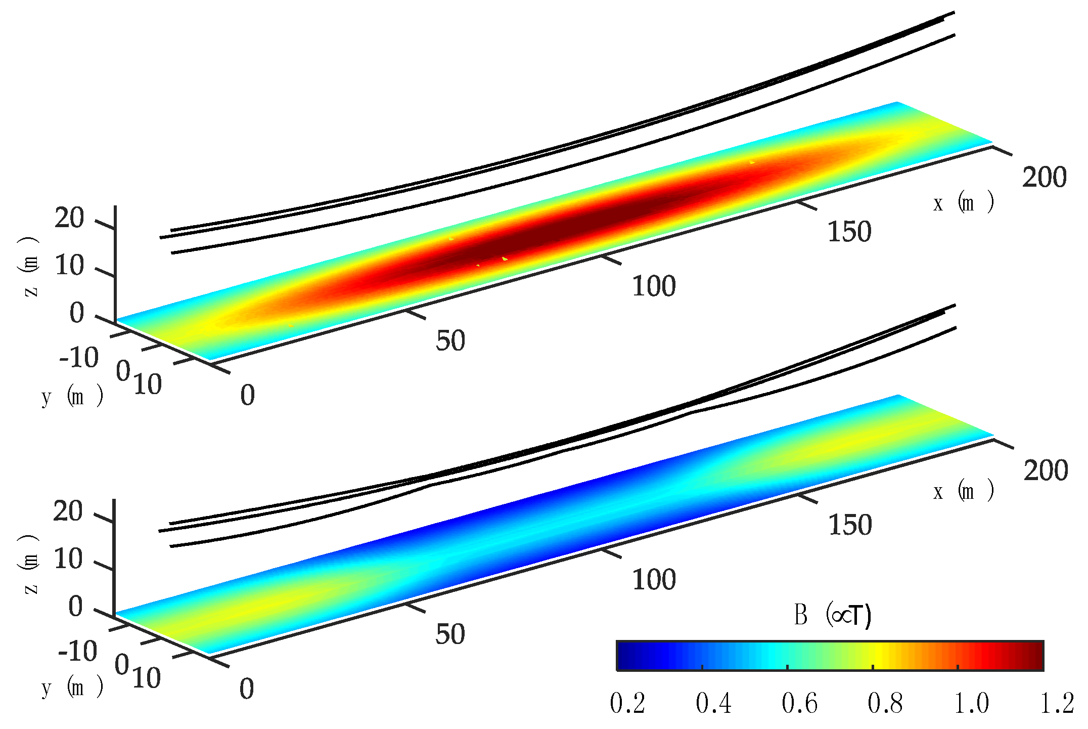
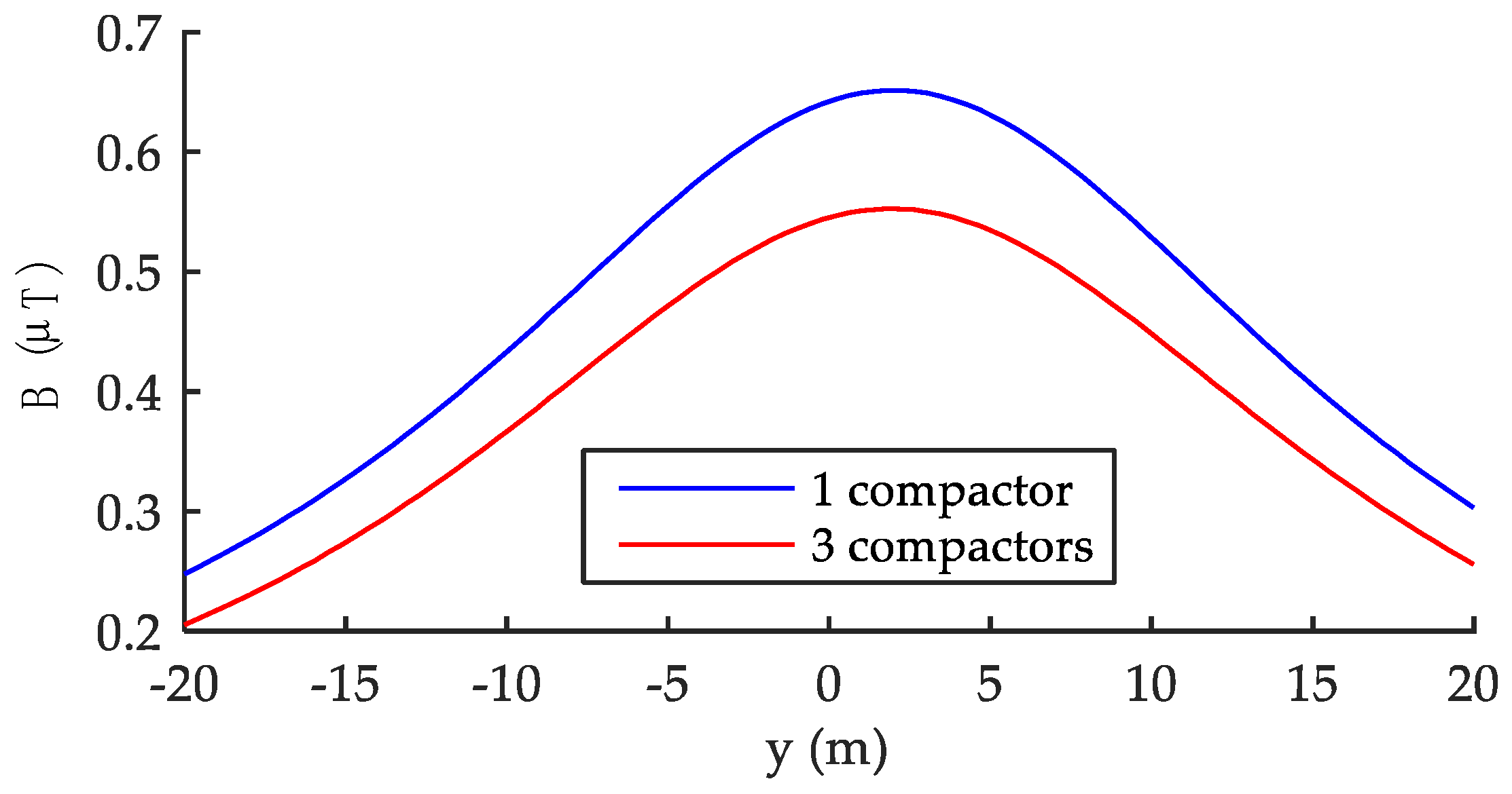
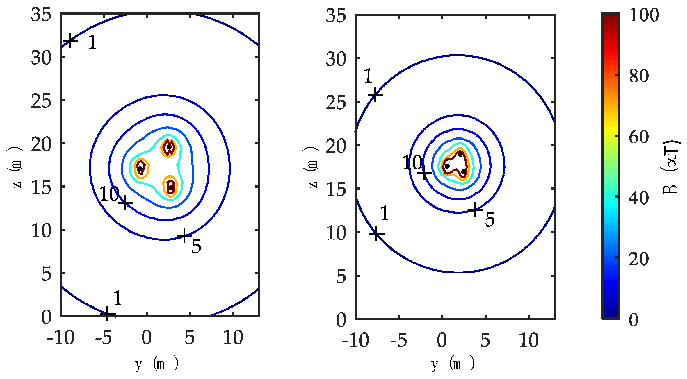
Figure 5 represents the magnetic induction field on a plane 1 m above the ground level in EDS conditions, without (above figure) and with compactors (lower figure). In the studied configuration, it is interesting to note that the magnetic induction in the span center is mitigated from 1.24 µT to 0.55 µT (−55.6%). Furthermore, with compactors, the magnetic induction decreases moving from towers (where the phase-to-phase distance is higher) to the center of the span (where approaching phase conductors compensates the lower distance between wires and the ground level). Differently, the area close to the span center is the most critical in the case of traditional installations.
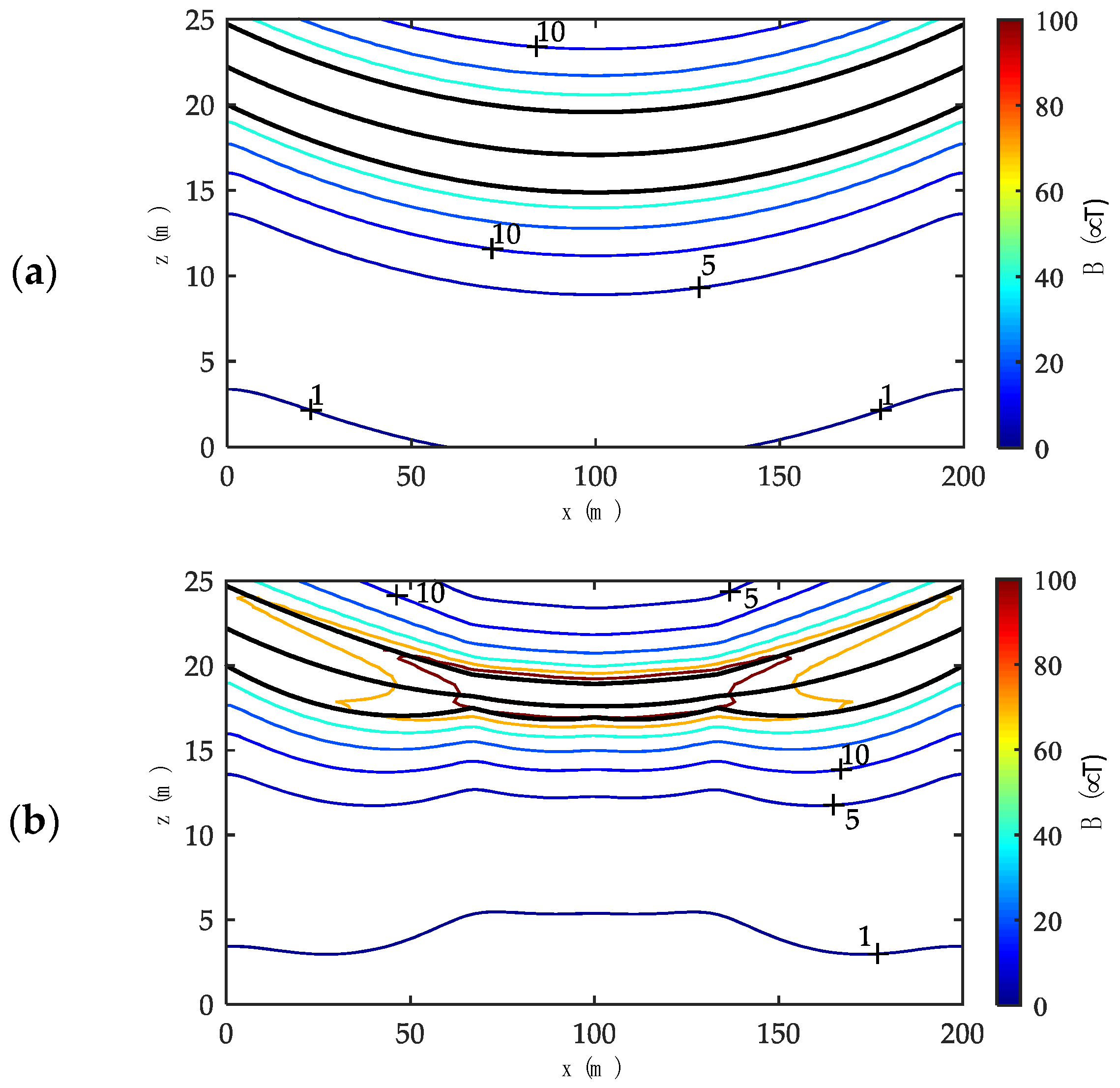
These results are confirmed by analyzing the curves of equal field strength in a transversal section orthogonally crossing the line in the span center (
Figure 6) and in a longitudinal vertical section passing through the compactors barycenter (
Figure 7). Both the figures refer to the EDS conditions. In particular,
Figure 7b clearly shows that the curve of equal field strength corresponding to 1 μT is a few meters higher than the ground level along all the span in the configuration with compactors.
4.2. Sensitivity Analysis
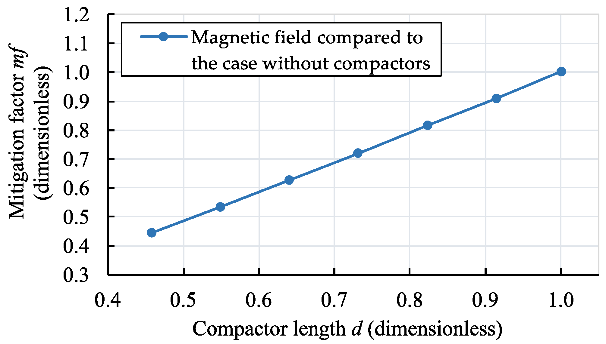
Figure 8 demonstrates how the magnetic field is linearly mitigated by reducing the compactors length (i.e., moving from 1.0 to 0.45 along the horizontal axis of the graph) due to both the reduction of the distance between phase conductors along the span and the indirect increase of the line barycenter. Consequently, a confirmation of the approximated Equation (1) is obtained.
The parameter d (dimensionless) represents the wires distance respect to the initial average wires distance equal to 4.38 m (i.e., d = 1 if compactors are not installed). Similarly, the mitigation factor mf (dimensionless) represents the magnetic induction at the span center in relative terms, i.e., in comparison to the maximum field obtained in the traditional configuration (without compactors), thus mf = 1 means no reduction.
As a result, the maximum rod insulators length, i.e., the side of the triangular compactors, is directly designable depending on the required magnetic field mitigation in comparison with the ex-ante configuration. In addition, the rod insulators absolute length
D has to be enough to guarantee the phase-to-phase insulation, in all the line operating conditions, as previously discussed with reference to [
30].
On the other hand, in
Figure 9 two mechanical aspects of the system equipped with compactors are emphasized. The barycenter height lightly increases if the compactors dimension decreases (
Figure 9a), giving a contribution in the magnetic field mitigation. In addition, the mechanical tension on the three wires is kept under control in comparison with the breaking load of the conductors, taking into account the previously described safety coefficients defined by [
30] for both the EDS conditions (when
sc1 = 0.25 is applied,
Figure 9b) and the MSA and MSB conditions (
sc2 = 0.50,
Figure 9c). For clarity, the graph reports only the results referred to the phase
U, since it is the one with the highest stress values. Although the stress behavior is not linear with the insulators dimension, a simple relationship can be established. It is important to note that variations in the mechanical operating conditions are not so worrying in terms of mechanical stresses, considering the admitted values dependent from the cross-sectional area and the prescribed safety coefficients
sc1 and
sc2.
Furthermore, in the case compactors are installed only along a single span and wires end points are free to lightly move along the line longitudinal axis (e.g., considering towers with V insulators), the authors have verified that the final equilibrium condition, including adjacent spans, is reached with reduced mechanical stresses on phase conductors, since the length of the span equipped with the compactors decreases of a few centimeters.
Another issue concerns the number of compactors to be added along the line span. One or more compactors can be inserted depending on the goal the designers want to achieve. In the base case, three compactors distributed at 1/3, 1/2 and 2/3 of the line length are considered. This choice: (i) reduces by half or more the magnetic induction at the span center; (ii) assures an opportune distance among the wires also in case of heavy environmental condition; (iii) optimizes the mechanical stresses on the wires; and (iv) ensures a mechanical redundancy in the infrequent case one of the rod insulators composing the compactors breaks. The configuration with a unique compactor along the span has been examined and compared with the base case with three compactors. As illustrated in
Figure 10 with reference to the EDS conditions, the magnetic induction 1 m above the ground level, evaluated in the span center along a direction orthogonal to the line axis (i.e.,
y = 0 m corresponds to the overhead line longitudinal axis), is higher in the case of single compactor, since this configuration entails a lower reduction of the span sag as regards to the base configuration with three compactors.
Once the number of compactors is defined, their position along the span is not arbitrary since this issue strongly influences the magnetic field mitigation.
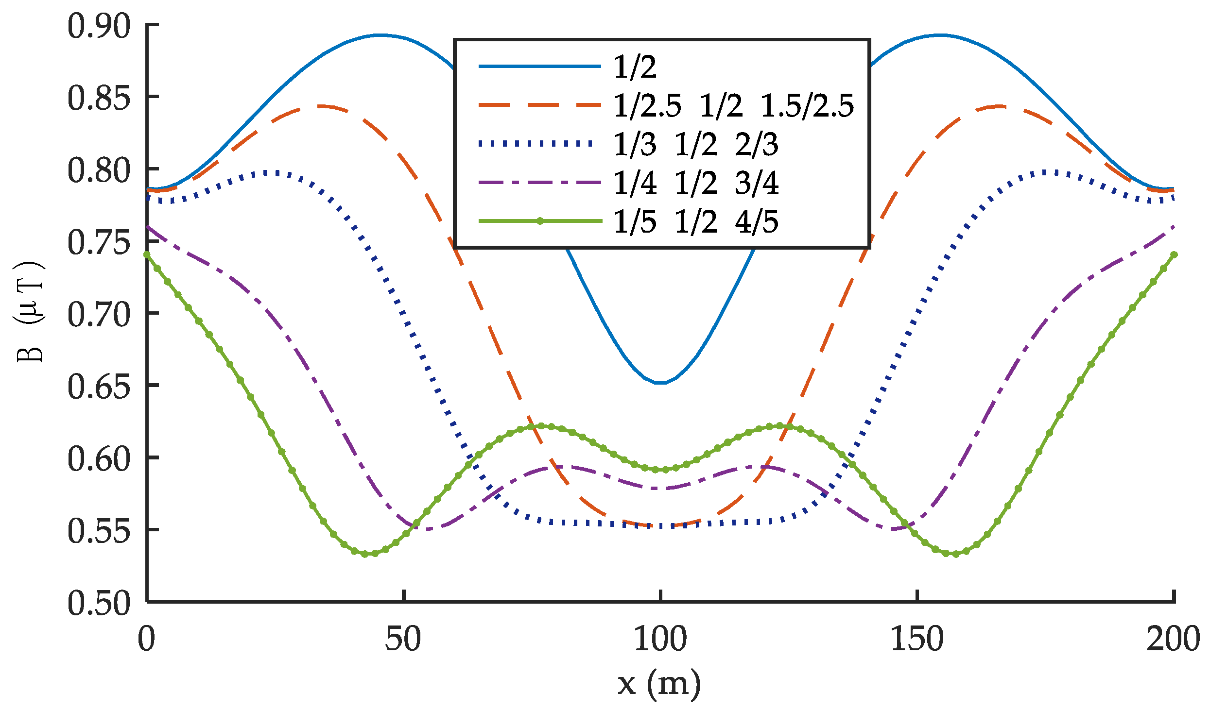
Figure 11 represents the magnetic induction along the span, 1 m above the ground level, in the case three compactors are positioned at different distances. The central one is always applied in the middle of the span (1/2 of the line length), whereas the other two are symmetrically located with respect to the span center. The comparative analysis represents 4 configurations in which the two external compactors are installed at 1/3-2/3 (base configuration, dotted blue line), 1/2.5-1.5/2.5, 1/4-3/4 and 1/5-4/5 of the span length. The continuous blue line represents the configuration with only one compactor.
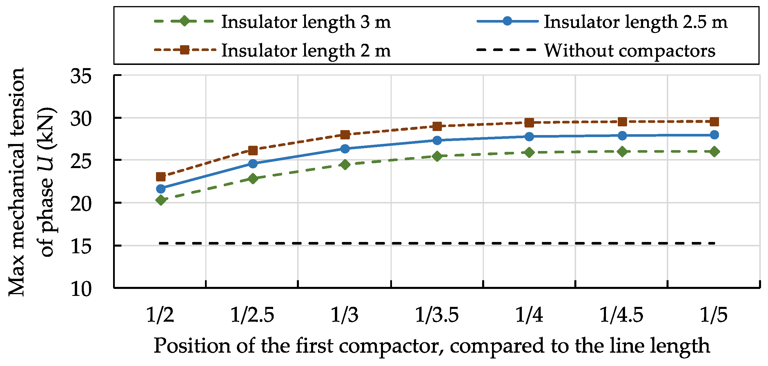
Figure 12 shows the maximum mechanical tension along the phase
U (the most mechanically stressed one) in EDS conditions, as a function of the position and the length of rod insulators composing the compactors. The
x-axis represents the position of the first compactor as regards to the line length (1/2 means a unique compactor in the central point of the span, while 1/3 is the base configuration). The third compactor is assumed to have a symmetrical position with respect to the line center. In each case, the maximum mechanical tension remains sensibly lower than the wire breaking load multiplied by the security coefficient
sc1 (which result equal to 39.0 kN). The trends depicted in
Figure 11 and
Figure 12 justify the insertion of external compactors at 1/3 and 2/3 of the span length (base configuration).
5. Conclusions
A procedure for the evaluation of the benefits in terms of magnetic field passive mitigation achievable by installing compactors along overhead line spans (realized through rod insulators forming equilateral triangles) has been developed and discussed. Knowing the basic line data (wire characteristics, tower type, span length, etc.), the methodology evaluates the conductor layouts in the three-dimensional space, computes the mechanical stresses on each line component and estimates the advantages in terms of magnetic field mitigation.
Simulation results demonstrate that, introducing one or more compactors, the ground-level magnetic field significantly decreases. Consequently, the current flowing along the line is no longer constrained by environmental issues and areas close to the transmission line may be better exploited without significant limitation derived by the long-term human exposure to the magnetic field. These positive impacts are obtained by reducing both the phase-to-phase distances along the span (constrained by compactors) and the line sag, as consequence. A tolerable increase of mechanical stresses on some line components has been observed, depending on both the number and the side length of compactors. Although the insertion of a sole compactor in the center of the span is enough to sensibly reduce the ground-level magnetic pollution, the configuration with three compactors at 1/3, 1/2 and 2/3 of the span length seems to be the optimal configuration jointly analyzing the mechanical constraints and the expected benefits in terms of magnetic field mitigation.
Finally, it is important to note that the investigated action is easily applicable to both new constructions and existing lines. A 56% reduction of the maximum ground-level magnetic field has been demonstrated as regard to an overhead transmission line realized with compacted towers (the solution that, at present, minimizes the magnetic field without compactors). Higher relative benefits are easily achievable in the case of traditional towers with suspended insulators.
Suitable analyses of the environmental impact caused by compactors, as well as their influence in terms of additional mechanical stresses on both tower insulators and tower structures, are strictly required before applying the proposed passive mitigation method.


