Article

A Floating Platform with Embedded Wave Energy Harvesting Arrays in Regular and Irregular Seas

1
State Key Laboratory of Advanced Design and Manufacturing for Vehicle Body, Hunan University, Changsha 410082, China
2
School of Civil Engineering & Architecture, Xiamen University of Technology, Xiamen 316005, China
3
China Ship Scientific Research Center, Wuxi 214082, China
*
Author to whom correspondence should be addressed.
Energies 2017, 10(9), 1348; https://doi.org/10.3390/en10091348
Submission received: 23 July 2017 / Revised: 24 August 2017 / Accepted: 29 August 2017 / Published: 6 September 2017

Abstract

:
This paper presents a study on a cost-effective engineering model that integrates an array of floating wave energy converters with a vast platform, a viable option for multi-functional performance in renewable energy capture and ocean space utilization. The wave energy converters are floating buoyance columns flexibly connected with the elastic platform. Hydrodynamic interactions among the columns are analyzed using an exact matrix transform method based on linear wave theory in the frequency domain. A parametric governing equation of compounded wave energy converter referred to as a wave farm is formulated by using Hamilton’s principle which can be discretized using the Galerkin method. The effects of wave conditions and the parameters of hydraulic power take-off (PTO) on the wave energy absorption and dynamic characteristics of the energy harvesting system are investigated. Furthermore, the wave energy capture on irregular waves is also discussed. This research work aims at providing a theoretical guidance for wave energy harvesting system design.

1. Introduction

Wave energy, one of the four main sources of ocean renewable energy (wave energy, tidal energy, ocean thermal energy and offshore wind energy), is extremely abundant since it is estimated at around 2 TW worldwide [1]. Utilization of wave energy has various significant advantages, such as a low level of negative environmental impact [2,3], high energy density [4] and continuous power supply during the whole day [5], in comparison with other forms of renewable energy. According to the present situation, however, the cost of utilization of wave energy is much higher than that of large-scale traditional power generation stations [6] due to their low efficiency. Multifunctional structures embedded with wave energy converters (WECs) may be a promising alternative to make WECs more competitive [7].
There are a few novel concepts for multipurpose compounded structures for wave energy harvesting which are not limited to those listed below. In order to integrate wave energy converters with shore-protection structures, a flexible floating breakwater consisting of multiple WEC modules installed between adjacent modules are proposed by Michailides and Angelides [8]. Their results showed that a desired level of protection by the flexible floating breakwater could be achieved by the integrated effect of WECs. A similar structure which integrates oscillating-water-column (OWC) converters with floating breakwaters was proposed by He et al. [6]. Asymmetric pneumatic chambers attached to a floating breakwater were designed to improve the performance in wave energy extraction via enhancing the resonance of the oscillating water column inside the chambers over a wide range of wave frequencies. The corresponding experimental study was carried out to verify the theoretical analysis under regular wave conditions. Apart from the literatures listed above, there are a lot of studies about compounded breakwater system integrated with wave energy converters, such as floating breakwaters attached with a pile-supported OWC structure [9], rubble mound breakwaters with embedded collecting wave reservoir type or Savonius rotor type WECs [10,11], etc. On the other hand, most remote ocean areas like islands are far from the power grid, so providing electricity from a land power grid to these areas is often costly and non-environmentally friendly [12]. In such cases, applying a renewable energy system in remote places has been the best choice [13,14]. In certain islands, the near-shore wave energy is shown to be a proper renewable energy source for power supply [15]. In addition, ocean space resources, energy resources, chemical resources, etc., for remote locations are more and more important due to the heavily-used land space and energy shortage. A multifunctional floating system for powering harbors, tourist resorts or manufacturing bases embedded with wave energy harvesting and storage is economically preferable. Fiaschi et al. proposed a novel offshore platform used as a compressed air energy storage (CAES) system integrated with three energy storage systems [16]. They conceived that this removable multipurpose offshore power platform can be used for special users such as tourist resorts or villages in small or medium islands. Zinni patented a ‘Modular Floating Pier and Integrated Multipurpose Generator of Energy from Renewable Sources’ to be used as an infrastructure aimed at the generation of electricity, thermal energy and CAES from renewable sources in addition to fulfilling the normal functions of a floating pier or platform at the service of boating, beach resorts and maritime activities in general [17]. Hartono proposed a novel floating housing for equipment coupled with a wave energy generation system [18]. The same author also proposed very large floating structures (VLFS) used as floating offshore airports [19]. Different from the pontoon-type VLFS proposed above, a semi-submerged VLFS consisting of a thin upper hull and a great number of buoy columns has also widely been studied in order to reduce hydrodynamic interactions [20,21]. With this motivation, a multi-usage platform supported by an array of floating buoys can form a multi-purpose wave farm where PTOs embedded between the columns and the upper platform act as devices for energy extraction. In addition, the large floating platform can be utilized in various fields such as offshore airports [22], marine cities, energy farms [23], fuel storage facilities [24], etc. to better utilize the ocean space and resources [25].
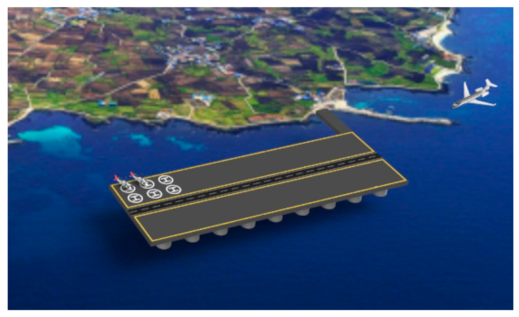
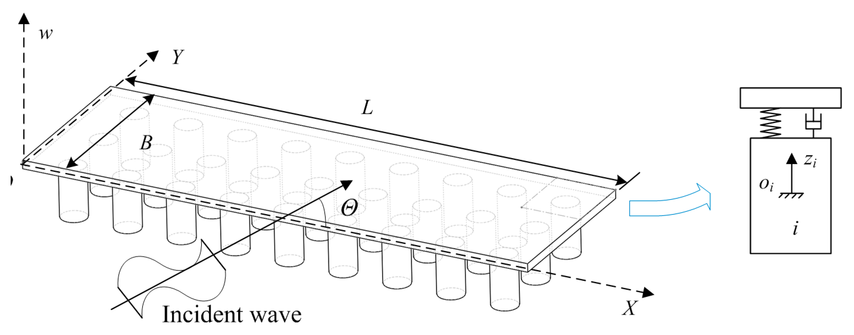
In this paper, a novel integrated wave energy farm model is proposed and its dynamic characteristics are examined. The wave energy harvesting system consists of an array of buoyance columns connected with a flexible platform which is not only a wave energy harvesting system, but also a vast floating platform for various purpose services. The platform, modeled as a classical plate, is coupled with multiple buoyance columns through linear connectors. A linear hydraulic PTO mechanism with linear damping coefficient is installed between each column and the platform to extract wave energy. The hydrodynamic interactions among the multiple buoyance columns are analyzed using an exact algebraic method in the frequency domain. A parametric dynamic model is formulated by using Hamilton’s principle which can be discretized using the Galerkin method. The effect of the parameters for the PTO and the connector on displacement of the platform and the wave energy absorption are analyzed for regular and irregular waves. This study provides a new insight and theoretical guidelines for the design of wave energy farms.

2. Mathematical Modeling

The integrated wave energy farm proposed in this paper consists of an array of buoyance columns supporting a flexible platform. The conceptual model is shown in Figure 1. The draught and radius of each buoyance column are defined by R and d respectively. The corresponding PTO between a floating buoyance column and the platform is actuated by the relative motion which in turn exerts a load proportional to this relative motion. The linear PTO mechanism is mathematically modeled by a linear damper. Linear wave theory is used in the present paper under constant water depth h . For the sake of simplicity, only the heave motions (i.e., along the vertical axis) for the floating buoyance columns are considered, with all other degrees of freedom ideally restricted.

2.1. Governing Equation of Wave Energy Harvesting System

In this paper, the platform modeled as a plate has vertical rigid-body motion and elastic deformation due to vertical deflection. The w O X Y reference is introduced to determine the motion of the platform. The origin point o i of the o i z i reference is set at the water free surface and the zi-axis measures the displacement of the i-th buoyance column, shown in Figure 2. The vertical rigid-body motion of the plate is described by w ¯ 0 ( t ) and the elastic deformation is denoted by w ¯ ( X , t ) in which the symbol X = ( X , Y ) denotes the position function.
In this paper, the Hamilton principle is used to derive the dynamic model for the wave energy harvesting system:
t 1 t 2 ( δ K δ U + δ W ) d t = 0 ,
where t 1 , t 2 is the arbitrary instants in time. δ indicates the variational symbol and the symbols K , U , W denote the kinetic energy, potential energy and work done by the non-conservative forces.
The kinetic energy for the plate [26] and multiple buyances can be formulated as:
K p = 1 2 Ω ρ s [ ( w ¯ ˙ 0 + w ¯ t ) 2 ] d X d Y , K b = 1 2 i = 1 N b m i z ˙ i 2 .
Thus the kinetic energy for the wave energy harvesting system is given by:
K = K p + K b = 1 2 Ω ρ s [ ( w ¯ ˙ 0 + w ¯ t ) 2 ] d X d Y + 1 2 i = 1 N b m i z ˙ i 2 ,
where the superscript dot indicates differentiation with respect to the time. ρ s indicates the surface density of the platform, N b denotes the total number of the buoyance columns, m i is the mass of the i-th buoyance column.
The elastic potential energy of a plate U p is given by [26]:
U p = 1 2 D Ω 0 { ( 2 w ¯ X 2 + 2 w ¯ Y 2 ) 2 2 ( 1 ν ) [ 2 w ¯ X 2 2 w ¯ Y 2 ( 2 w ¯ X Y ) 2 ] } d X d Y ,
where D is the flexural stiffness of the plate and ν denotes Poisson’s ratio.
Considering a linear PTO with a damping coefficient C D and a flexible connector modeled by a linear spring with a linear stiffness K S installed between the i-th buoyance column and the plate at the position of X i shown in Figure 2. The connector force induced by the relative motion between the buoyance column and plate can be written as:
F i c = K S V ¯ i ,
where V ¯ i denotes the relative displacement referencing the i-th buoyance column coordination, it yields:
V ¯ i = w ¯ 0 ( t ) + w ¯ ( X i , t ) z i .
The force that is produced from the i-th PTO is calculated according to the equation below:
F i p = C D V ¯ ˙ i .
Considering the wave farce F i w imposed on the i-th buoyance column, the virtual potential energy δ U c of the connector and the virtual work done δ W by the wave farce F i w and damping load of the PTO imposed on i-th buoyance column are given by:
δ U c = i = 1 N b { F i c δ V ¯ i } , δ W = i = 1 N b { F i w δ z i F i p δ V ¯ i } .
Thus substituting Equations (3), (4) and (8) into Equation (1), and using integration by parts, we can obtain the governing equations of the wave energy harvesting system in which the platform model governed by a partial differential equation (PDE) and the buoyance columns model governed by ordinary differential equations (ODEs), given by:
ρ s ( w ¯ ¨ 0 + 2 w ¯ t 2 ) + D 4 w ¯ + i = 1 N b C D δ ( X X i ) [ w ¯ ˙ 0 + w ¯ t z ˙ i ] + i = 1 N b K S δ ( X X i ) [ w ¯ 0 + w ¯ z i ] = 0 , 0 < X < L ;    0 < Y < B , m i z ¨ i + C D [ z ˙ i w ¯ ˙ 0 w ¯ ( X i , t ) t ] + K S [ z i w ¯ 0 w ¯ ( X i , t ) ] = F i w ,   i = 1 , 2 , , N b ,
where δ ( X X i ) indicates the Dirac function.
Based on linear wave theory [27], the fluid forces in time evolution form can be written as:
F W = K z + ( F e + F r ) e i ω t ,
where z denotes the displacement vector of buoyance columns, ω indicates the wave frequency. The two terms on the right hand of Equation (10) indicate the hydrostatic restoring force and wave force derived from static and dynamic pressure, respectively. K denotes the hydrostatic restoring matrix in which diagonally elements satisfy K i i = ρ g π R 2 and other elements are zeros, where ρ , g indicate water density and gravity acceleration, respectively. F e , F r indicate the complex amplitude vectors of the harmonic exciting wave force and radiation wave force, respectively, and the radiation wave force can be formulated as:
F r e i ω t = ( μ z ¨ + λ z ˙ ) ,
where μ , λ indicate the hydrodynamic coefficient matrices referred to as added mass and added damping. The elements of wave forces F e and hydrodynamic coefficient matrix μ , λ can be determined by using an exact matrix transform method suggested by Siddorn and Taylor [28] which takes into account wave interactions among columns. The hydrodynamic problem for a single buoyance column is solved by using the eigenfunction expansion matching method [29] and the interaction among different buoyance columns is considered by using the addition theorem for Bessel functions [30]. In order to simplify the modeling process, we only cite the relevant references here for the well-developed hydrodynamic model for further reading without involving detailed mathematic derivations.
Substituting the wave force expression (9) into Equation (8), the governing equation of the compounded wave energy farm can be written as:
ρ s ( w ¯ ¨ 0 + 2 w ¯ t 2 ) + D 4 w ¯ + i = 1 N b C D δ ( X X i ) [ w ¯ ˙ 0 + w ¯ t z ˙ i ] + i = 1 N b K S δ ( X X i ) [ w ¯ 0 + w ¯ z i ] = 0 , 0 < X < L ;    0 < Y < B , m i z ¨ i + j = 1 N b ( μ i j z ¨ j + λ i j z ˙ j ) + K i i z i   + C D [ z ˙ i w ¯ ˙ 0 w ¯ ( X i , t ) t ] + K S [ z i w ¯ 0 w ¯ ( X i , t ) ] = F e i e i ω t ,   i = 1 , 2 , , N b .
The governing Equation (12) carries a PDE that needs to be converted into ODEs by using the Galerkin method. Thus, the deflection of the plate w ¯ ( X , Y , t ) is expressed in the form as:
w ¯ ( X , Y , t ) = j = 0 N X l = 0 N Y w j l ( t ) φ j l ( X , Y ) = j = 0 N X l = 0 N Y w j l ( t ) Π j ( X ) Ψ l ( Y ) ,
where N X , N Y denote the order of eigenfunction. Π j ( X ) , Ψ l ( Y ) indicate the eigenfunction in which j , l > 0 denotes elastic deformation, written as [31]:
Π j ( X ) = cos κ x j X + cosh κ x j X cos κ x j L cosh κ x j L sin κ x j L sinh κ x j L ( sin κ x j X + sinh κ x j X ) , j = 1 , 2 , ,
where the j-th eigenvalue κ x j is satisfied with the following eigenequation:
cos κ x j L cosh κ x j L 1 = 0 .
For rigid modal we define Π 0 ( X ) = 1 . A similar form for the eigenfunction Ψ l ( Y ) in transverse direction can be formulated with X replaced by Y in Equation (14) and the eigenequation (15) is also modified with L replaced by B . Substituting Equation (13) into the governing Equation (12) and use of the general Galerkin method yields:
ρ s j = 0 N X l = 0 N Y Δ j l , r s w ¨ j l + D j = 0 N X l = 0 N Y Ξ j l , r s w j l = i = 1 N b { K S [ z i ( t ) j = 0 N X l = 0 N Y w j l φ j l ( X i ) ] } φ r s ( X i ) + i = 1 N b { C D [ z ˙ i j = 0 N X l = 0 N Y w ˙ j l φ j l ( X i ) ] } φ r s ( X i ) , r = 0 , 1 , , N X ;   s = 0 , 1 , , N Y , m i z ¨ i + j = 1 N b ( μ i j z ¨ j + λ i j z ˙ j ) + K i i z i = F e i e i ω t + K S [ j = 0 N X l = 0 N Y w j l φ j l ( X i ) z i ] + C D [ j = 0 N X l = 0 N Y w ˙ j l φ j l ( X i ) z ˙ i ] , i = 1 , 2 , , N b ,
where:
Δ j l , r s = Ω 0 φ j l ( X ) φ r s ( X ) d X d Y ,   Ξ j l , r s = Ω 0 ( 4 φ j l ( X ) ) φ r s ( X ) d X d Y ,
here the details expressions of Δ j l , r s , Ξ j l , r s are given in the Appendix A.
For simplicity, we rewrite Equation (16) into a matrix form:
[ M w w 0 0 M z z ] [ w ¨ z ¨ ] + [ C w w C w z C z w C z z ] [ w ˙ z ˙ ] + [ K w w K w z K z w K z z ] [ w z ] = [ 0 F e ] e i ω t .
The governing equation of the system is linear and can be solved easily with the assumed solution [ w , z ] T = [ W ¯ , Z ¯ ] T e i ω t , where W ¯ , Z ¯ indicate the complex amplitude vectors of the plate and buoyance columns.

2.2. Wave Energy Absorption

From Equation (6) and (13), the relative motion V ¯ i between the i-th buoyance column and the plate can be formulated as:
V ¯ i = V i cos ( ω t + φ i ) = Re { ( j = 0 N X l = 0 N Y W ¯ j l φ j l ( X i ) Z ¯ i ) e i ω t } ,
where V i , φ i indicate the amplitude and phase of the relative motion.
The rate of wave power conversion by the i-th PTO can be defined the work done by the damping force per second:
E a i = 1 T t t + T C D V ¯ ˙ i 2 d t .
Substituting Equation (19) into (20), gives:
E a i = C D 2 ω 2 V i 2 .
Because of linearity, the extracted power of the i-th PTO in irregular incident waves is given as:
E ¯ a i = 0 E a i ( ω ) S ( ω ) d ω ,
where S ( ω ) indicates the frequency spectrum of incident waves. In this paper, the standard JONSWAP spectrum S ( ω ) is introduced with choosing frequency spreading parameter γ = 3.3 [32], written as:
S ( ω ) = β J H s 2 T p 4 ( ω 2 π ) 5 exp [ 1.25 ( T p ω 2 π ) 4 ] γ exp [ ( T p ω 2 π 1 ) 2 / 2 σ 2 ] ,
where:
β J = 0.06238 0.230 + 0.0336 γ 0.185 ( 1.9 + γ ) 1 [ 1.094 0.01915 ln γ ] , T p = T s 1 0.132 ( γ + 0.2 ) 0.559 , σ = { 0.07 ω ω p 0.09 ω > ω p ,
here T s and H s denote the significant wave period and significant wave height respectively, T p indicates the peak period.
Based on linear wave theory, the rate of regular incident wave power per meter of wave-front length can be formulated by [33]:
E I = 1 2 ρ g a 2 c g ,
where a denotes wave amplitude and the group velocity c g is defined as:
c g = ω 2 k ( 1 + 2 k h sinh ( 2 k h ) ) ,
where k = 2 π / λ indicates wave number satisfied the dispersion relationship ω 2 = g k tanh k h where λ denotes wave length. And the irregular incident wave power can also be calculated according to analogy Equation (22). Capture width is always introduced to evaluate the performance of a wave energy converters, for regular wave or irregular wave defined as [34]:
C W = i = 1 N b E a i E I   o r C W = i = 1 N b E ¯ a i E ¯ I ,
where the summations in numerator denote the total wave power extracted by the energy harvesting system in regular or irregular seas [35].

3. Numerical Results and Discussion

The pertinent information of the compounded wave energy farm is given in Table 1 partially referenced in [20]. For the wave parameters, the wave period is spanned in the interval of 8 ~ 20   s for regular waves.
For the convenience of analysis, we choose ρ , B , T as the characteristic variables to nondimensionalize the floating system parameters. The non-dimensional parameters for the model are defined as [23]:
K S = K S T 2 ρ B 3 ,   C D = C D T ρ B 3 ,   L = L / B
The non-dimensional capture width which performs the efficiency of the energy harvesting system is defined as C W = C W / B . The non-dimensional wave number which denotes the relationship between the wave length and structure size defined as k = k B . As commonly adopted, the displacements of the platform and the buoyance columns are nondimensionalized by using the wave amplitude w = w / a , z = z / a which is also named as the response amplitude operator (RAO).
In the following, we firstly study the effect of system parameters, the coefficients of connector stiffness and PTO’s damping, on the energy absorption characteristics, and then, the effect of wave parameters on energy absorption and dynamic characteristics of the floating system is analyzed in regular seas. This aims to gain a better understanding of the performance of the wave energy harvesting system. Finally, the wave energy absorption characteristics in various wave conditions are studied in irregular seas.
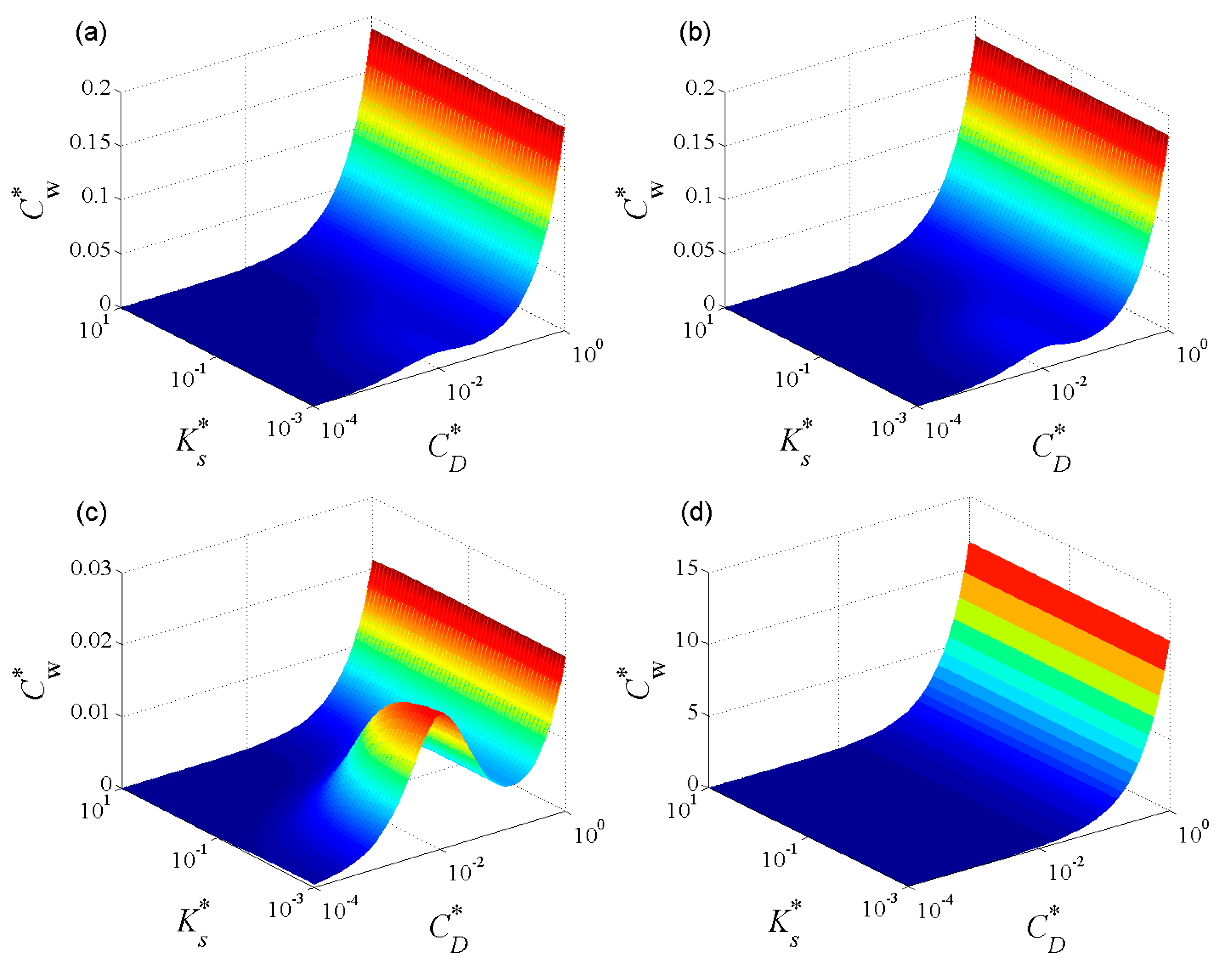
Figure 3 shows the 3D diagram of the capture width of the wave energy harvesting system in parameter space ( K S , C D ) for four different wave angles Θ = 0 , π / 8 , π / 4 , π / 2 with wave number k = 5.3050 (corresponding to wave period T = 10   s ). From Figure 3 we can see that the capture width almost stays at a relative small value while there are small resonance peaks like hills for some certain wave angles in the relative small damping region. With the increase of damping coefficient, the capture width increases exponentially. Different from the damping coefficient, the effect of stiffness coefficient on capture width is less sensitive.
Comparing the four cases of different wave angles, the trends for different wave angles are always similar, while the capture width for wave angle Θ = π / 2 is much larger compared with that of any other three wave angles. In order to clearly reveal the effect of wave conditions on energy absorption, we take the certain stiffness and damping coefficient picked at K S = 0.04 and C D = 0.001 to illustrate the following results.
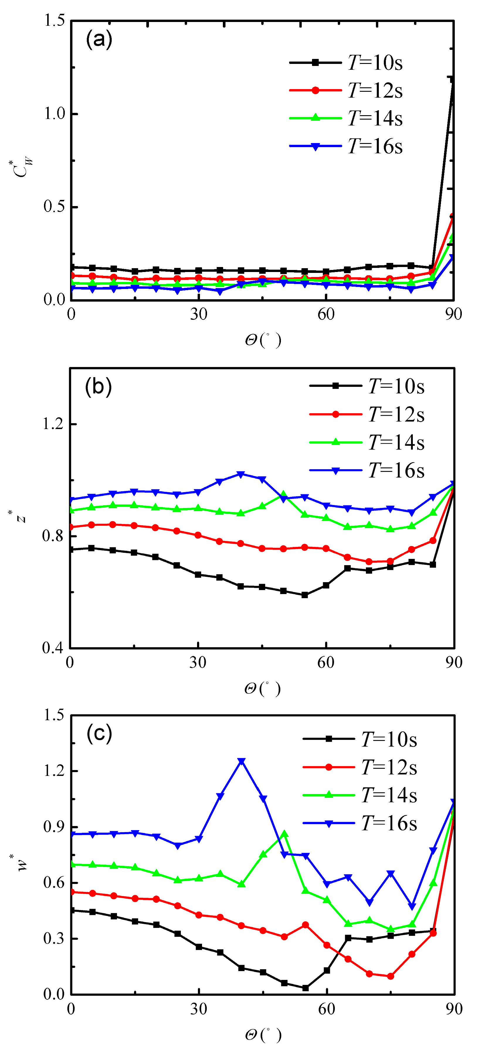
Figure 4 illustrates the wave energy capture width and the maximum response amplitudes of the energy harvesting system under the change of incident wave angle. From Figure 4a, we can see that the capture width appears weak fluctuation in the range of 0 Θ 85 and rises sharply at incident wave angle Θ = 90 regardless of what wave period is considered.
Further referring to the response magnitudes in 
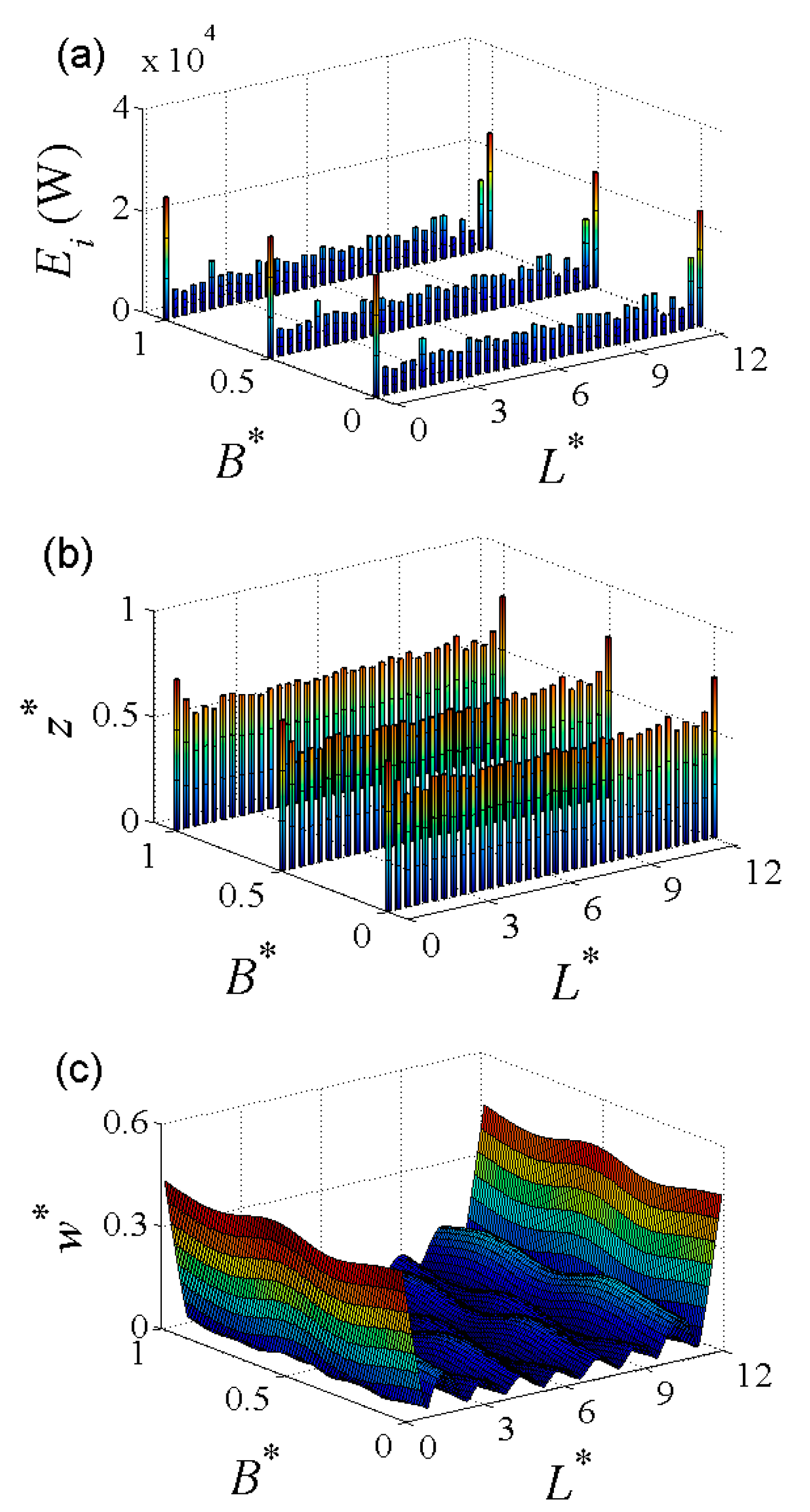
Figure 4b,c, we can see that the response amplitudes of the wave energy harvesting system under the change of incident wave angle have the same trend whereby that they first decrease and then increase with the increase of wave angle. There is a response peak in the middle wave angle range for different wave periods. Different from the capture width, the response amplitudes of the wave energy harvesting system change in the same order along the whole range of wave angle. In order to reveal the reason for the different trends between the capture width and response amplitudes under the change of wave angle, we plot the distribution of wave power extraction from each PTO and the platform deformation shape for two typical wave angle picked at Θ = 0 , π / 2 with wave number k = 5.3050 , shown in Figure 5 and Figure 6.
Figure 5a indicates the wave power extracted from each PTO located at different positions. The columns in Figure 5b illustrate the response amplitudes of the buoyance columns located at corresponding positions and Figure 5c indicates the deformation shape of the platform. From Figure 5a, we can see that the wave power extracted from the three rows PTOs has an identical distribution along the longitudinal direction while the PTOs located at the two ends capture almost four times wave power than that of others located in the middle region. The response amplitudes of buoyance columns, shown in Figure 5b, also have a similar trend as the capture width in that the two ends buoyance columns have larger motions. Considering the compounded system integration with wave energy capture with ocean space utilization, the stationarity for the upper platform is also important. The deformation shape of the platform, shown in Figure 5c, is corrugated, where the motions in the middle region are relatively weak while motions at the two ends of the upstream and downstream are relatively large, which coincides with the results for the traditional VLFS [20]. Due to the large scale of the platform, the gradient induced by the motions is still very small, so the platform can satisfy its functional requirement.
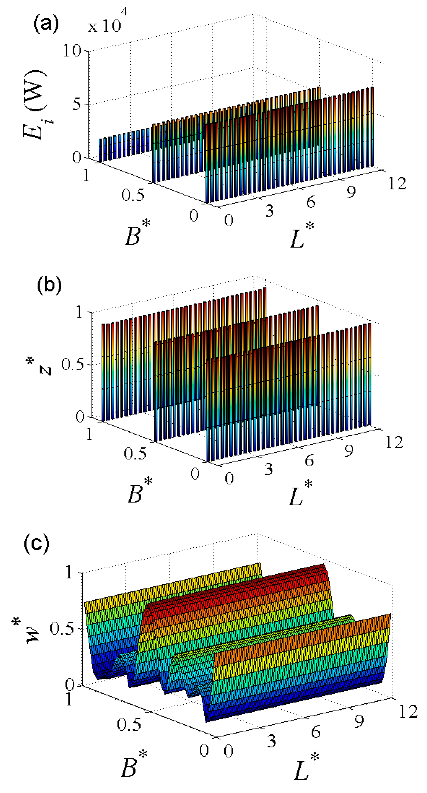
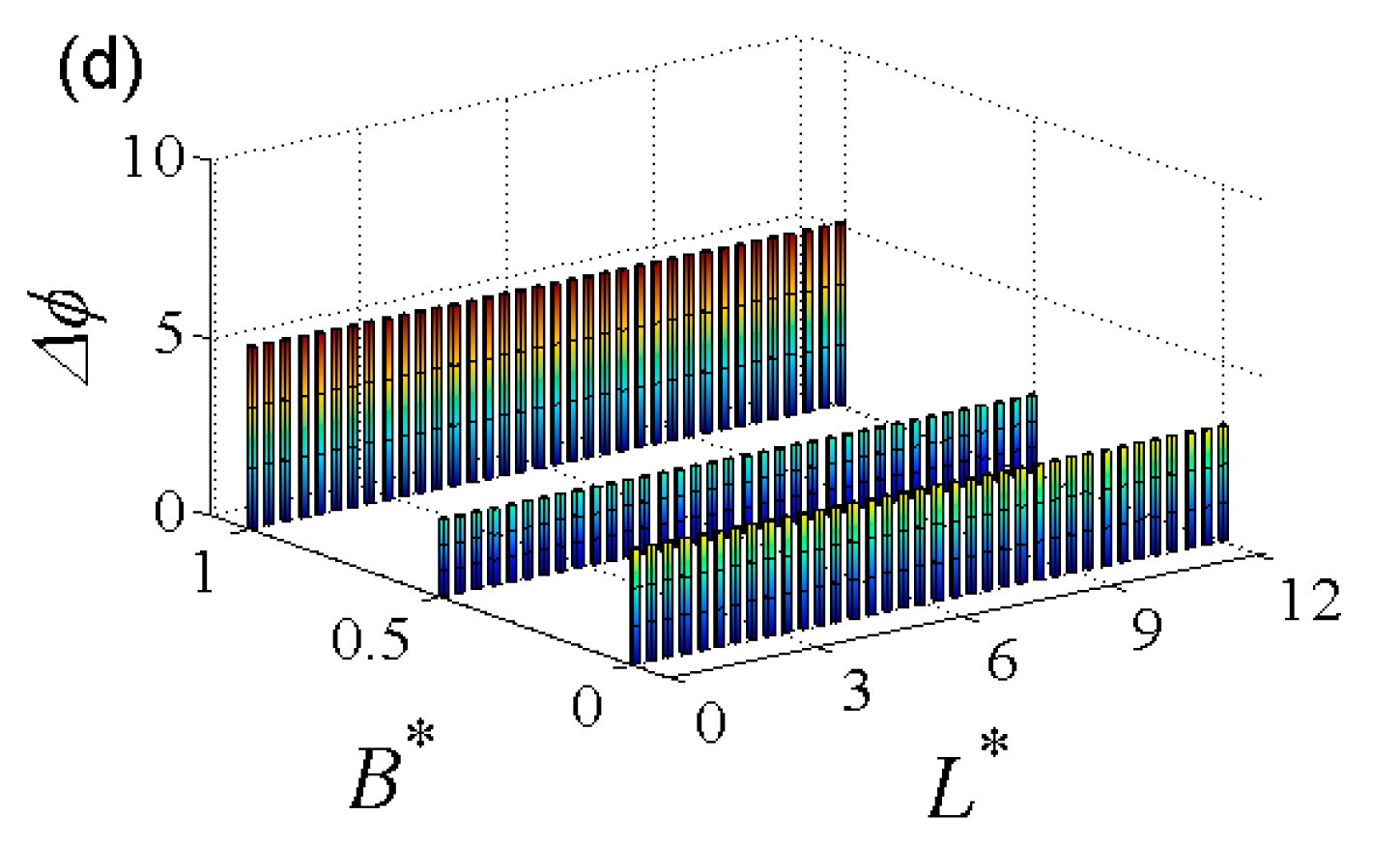
Figure 6 illustrates the wave power extraction and response amplitudes of the energy harvesting system in beam seas. From Figure 6b, the response amplitudes for the whole buoyance columns are almost the same while they are larger than the amplitude shown in Figure 5b. Due to the reason of beam seas, the deformation shape for the platform only fluctuates along the transverse direction. From Figure 6c, we can see that the wave number of fluctuation for the platform deformation in beam sea conditions is less than the wave number along the longitudinal direction shown in Figure 5c, which indicates that the low order eigenfunctions play a predominant role in beam seas. In fact, the reason for this is that the longitudinal stiffness is less than the transverse stiffness for the isotropic plate due to the large length in comparison with its width. From Figure 6a, we can see that the wave power extraction is also invariable along the longitudinal direction like the amplitudes shown in Figure 6b,c. Along the transverse direction, the wave power extraction from the three rows PTOs decreases while the displacements for energy harvesting system at the positions of the three rows are almost the same which seems not correct. When we reexamine the expression of wave power extraction (20), it is easy to find that the phase differences between the motions of buoyance columns and the corresponding position’s platform has an effect on the wave power extraction. We define the phase difference Δ ϕ i = | φ z i φ w ( X i ) | , where φ z i , φ w ( X i ) denote the initial phase for the i-th buoyance column and the platform located at X i . Figure 6d shows the corresponding phase differences. Similar to the above three subfigures, the phase differences are only variable along transverse direction, and the phase differences of the three rows are about Δ ϕ = 3.2 , 2.6 , 5.1 respectively. For the first row, the phase difference is about π which means that motions of the buoyance columns and the platform are almost anti-phase, so the wave power is larger than the other two rows even if the displacements of the buoyance columns and the platform are the same. Comparing Figure 5a and Figure 6a we can see that wave power extraction from the PTOs of the first row and(or) last row along the direction of wave propagation is many multiples larger than that from other rows. And the total number of the PTOs at upstream and downstream rows for the beam sea condition Θ = π / 2 is much larger than other wave conditions due to the rectangular structure. So the wave power extraction at wave angle Θ = π / 2 is greater than that at other wave angles which has also been revealed in Figure 3.
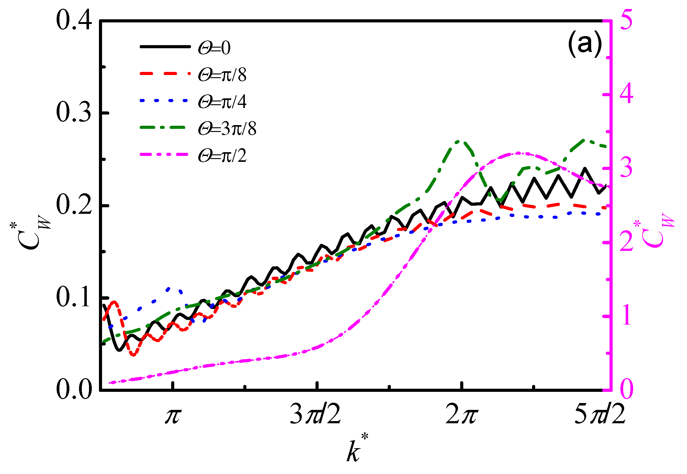
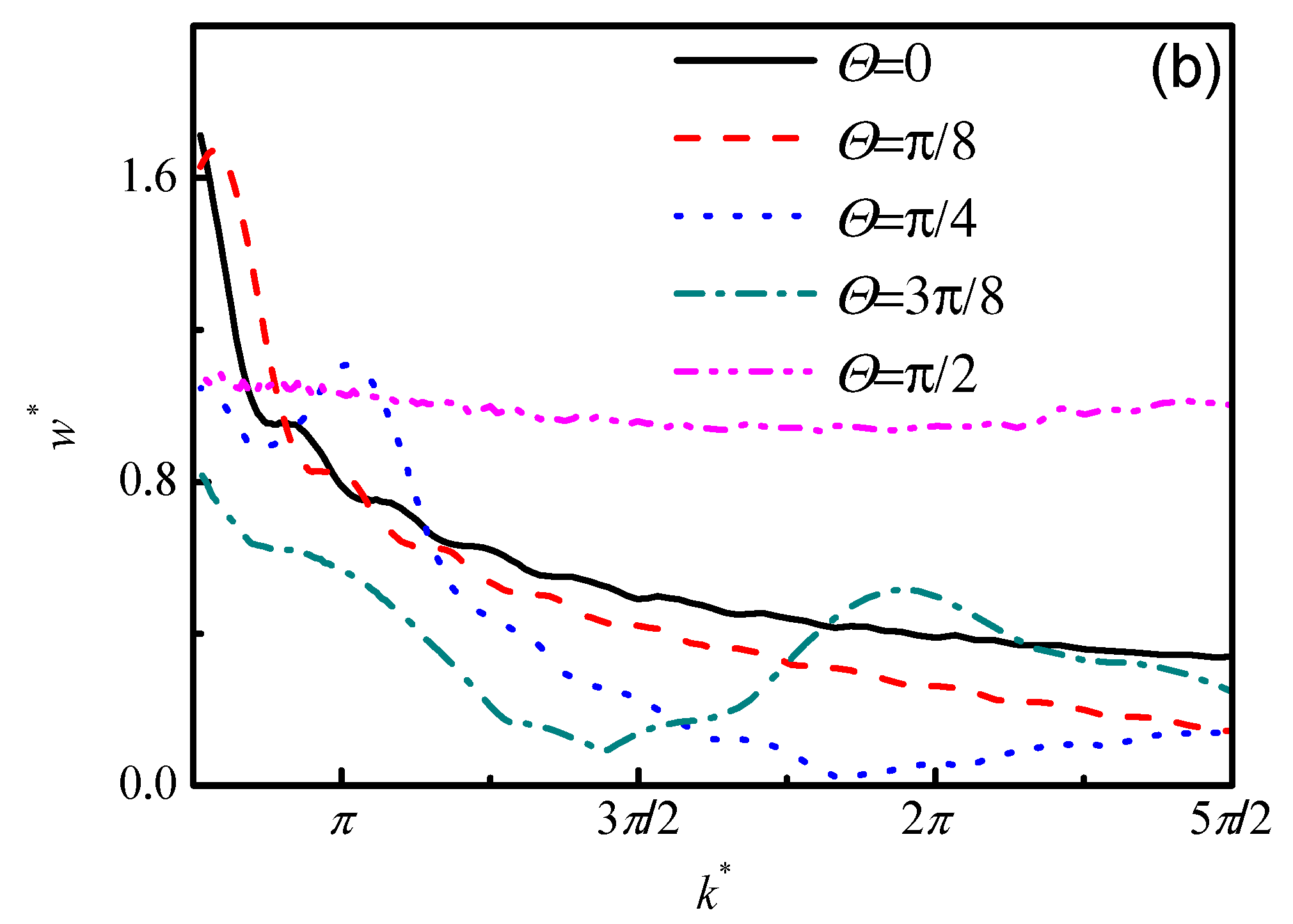
Figure 7 shows the capture width and the maximum amplitudes of the energy harvesting system under the change of dimensionless wave number k for five incident wave angles Θ = 0 , π / 8 , π / 4 , 3 π / 8 , π / 2 . Due to the different orders for the wave angle Θ = π / 2 and any other wave angles, the two vertical axes are used in Figure 7a. From Figure 7a we can see that the capture width for wave angle Θ = π / 2 is larger one order of magnitude than other four wave angles which is determined by the phase differences analyzed in above paragraph. The capture widths for different wave angles all increase with the increase of wave number for the five wave angles. In fact, the small wave number in Figure 7 corresponds to a larger wave length which is much larger than the spacing length for the array of buoyance columns.
For this reason, the motions for adjacent columns are almost in phase for small wave numbers and the fluctuation for the platform deformation is also weak [20]. Thus the capture width is small for small wave numbers. For the deformation of the platform shown in Figure 7b, the maximum amplitudes almost all decrease with the increase of wave number. The different evolutions between the capture width and the amplitudes of the platform may be also caused by the phase differences revealed in Figure 6.
Comparing Figure 7a,b, we can see that the capture width and the response amplitude have tiny peaks for wave angle Θ = π / 4 at about k = π and for wave angle Θ = 3 π / 8 at about k = 2 π . According to the definition for the non-dimensional wave number, the wave number k = π and k = 2 π are corresponding to wave length λ = 2 B and λ = B respectively. According to the above analysis, we can draw a conclusion about the characteristics of the wave energy harvesting system in regular seas. The system can capture much larger wave energy at a wave angle Θ = π / 2 .
In order to extract more wave energy, the PTO should be designed with a large damping coefficient. It is worth noticing that the stationarity of the platform is relatively worse for beam sea conditionss, although the wave energy extraction is superior. For a practical engineering application, we should consider the constraint values of the system parameters to balance the requirements for different functions when we design the wave energy harvesting system.
The results above are all under regular wave conditions, while realistic wave conditions are irregular. With this motivation, the results about wave energy capture of irregular waves for a significant wave height H s = 2   m are analyzed in the following paragraphs.
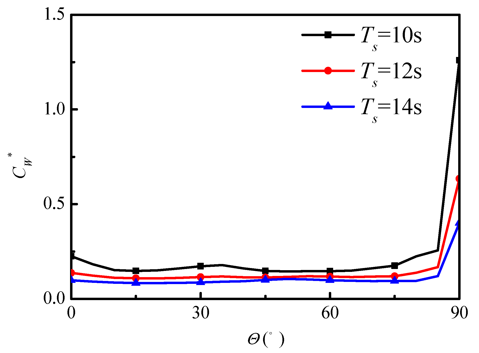
Figure 8 illustrates the capture width under the change of wave angle with stiffness coefficient K S = 0.04 and damping coefficient C D = 0.001 . With the increase of wave angle, the capture width appears small fluctuation in the interval of 0 Θ 85 and has a leap at wave angle Θ = 90 which is similar to that of the regular wave conditions shown in Figure 4a With the increase of significant wave period, the capture width decreases for different wave angles that coincides with the trend for regular wave shown in Figure 7a. In comparison with Figure 4 for regular waves, the trend of the capture width for irregular waves is the same with that for regular waves.
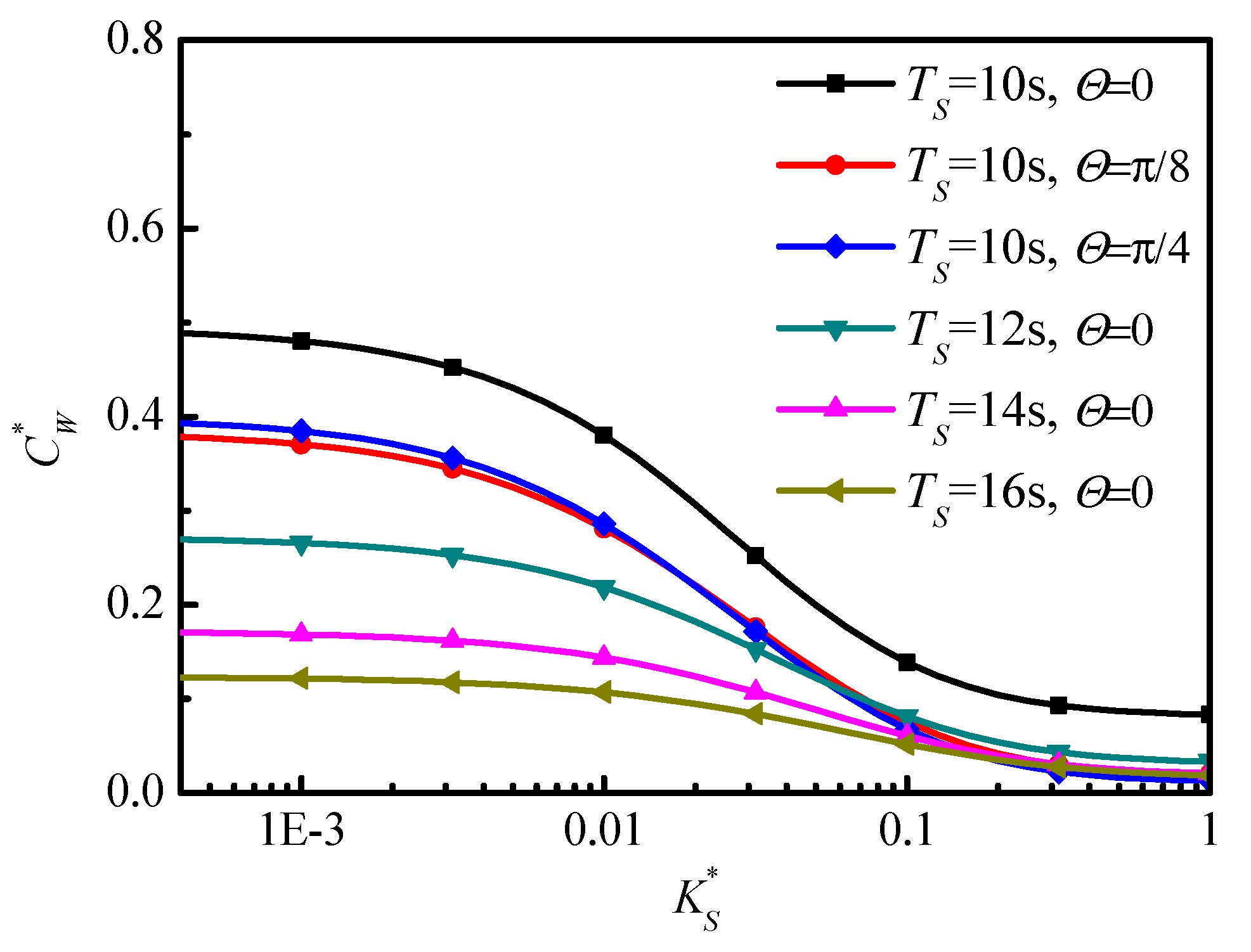
Similarly, the effects of connector’s stiffness and the PTO’s damping on the capture width also illustrate for irregular wave, shown in Figure 9 and Figure 10. With the increase of stiffness coefficient of the connector, the capture widths decrease firstly and then reach constant values for different wave angles and significant wave periods.
The reason for this phenomenon is that the relative motions between the plate and the buoyance columns are restrained with the increase of the stiffness of the connector. With the increase of significant wave period, the capture width decreases for different connector stiffness coefficients which has also revealed in 
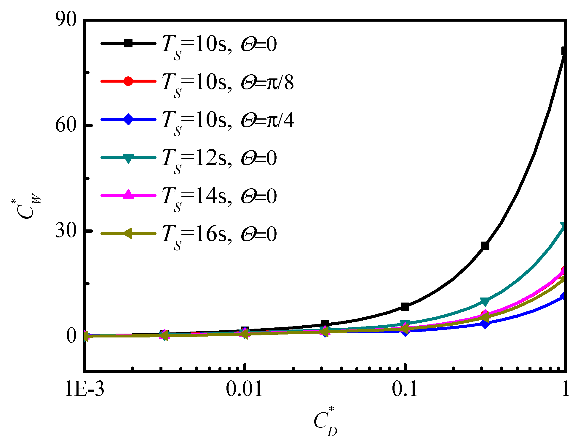
Figure 4a for regular waves. For the effect of the damping coefficient on capture width shown in Figure 10, the capture width increases with the increase of damping coefficient. The general trend of irregular waves is similar to that of regular waves while there is no small peak for irregular waves in comparison with Figure 3. For the different wave angles Θ = 0 , π / 8 , π / 4 with significant wave period T s = 10   s , the capture width decreases with the increase of wave angle (note that the red line with circles for wave angle Θ = π / 8 overlaps the pink line with up triangles for the significant wave period T s = 14   s shown in Figure 10).

4. Conclusions

In this study, a compounded wave energy farm consisting of an array of buoyance columns coupled with a flexible platform is proposed which can be a viable option for cost-sharing between a wave energy capture and ocean space utilization structures. For each buoyance column only the heave motion is considered and the platform is modeled as an isotropic plate. Hydraulic PTO mechanism with linear damping coefficient is introduced to be installed between each buoyance column and platform to harvest wave energy. Based on linear wave theory, hydrodynamic interactions among the columns are analytically studied using an exact algebraic method in frequency domain. A dynamic model is formulated by using Hamilton’s principle and solved by using the Galerkin method. The effects of the parameters of the PTO and connector on the energy absorption and the dynamic characteristics of the platform are analyzed in regular and irregular seas. The results show that the energy harvesting system can reach better performance for energy absorption at wave angle Θ = π / 2 due to the anti-phase motions between the buoyance columns and the platform, while the stationarity of the platform is relatively worse for beam sea conditions, although the wave energy extraction is superior. In order to extract more wave energy, the PTO should be designed with a large damping coefficient while a flexible connector with relatively small stiffness should be chosen. It is worth noticing that the phase control method [36] may be used to improve conflict between the wave energy extraction and the stationarity of the platform in future work.

Acknowledgments

This research work was supported by the National Natural Science Foundation of China (11702088, 11472100), the 973 research grant (2013CB036104) and the High-tech Ship Research Projects Sponsored by MIIT.

Author Contributions

Hai-Cheng Zhang, Dao-Lin Xu and You-Sheng Wu conceived and designed the research work; Hai-Cheng Zhang performed the numerical simulations and analyzed the data; Chun-Rong Liu contributed analysis tools; Hai-Cheng Zhang and Dao-Lin Xu wrote the paper.

Conflicts of Interest

The authors declare no conflict of interest. The founding sponsors had no role in the design of the study; in the collection, analyses, or interpretation of data; in the writing of the manuscript, and in the decision to publish the results.

Appendix A

The following are the expressions for the elements of Δ j l , r s , Ξ j l , r s :
Δ j l , r s = Ω 0 φ j l ( X ) φ r s ( X ) d X d Y = { L B j = r = 0 , l = s = 0 ϒ j ( κ x j , L ) ϒ l ( κ y l , B ) j = r > 0 , l = s > 0 0 o t h e r ,
Ξ j l , r s = Ω 0 ( 4 φ j l ( X ) ) φ r s ( X ) d X d Y = { ( κ x j 4 + κ y l 4 ) ϒ j ( κ x j , L ) ϒ l ( κ y l , B ) + 2 T j ( κ x j , L ) T l ( κ y l , B ) j = r 0 , l = s 0 0 o t h e r ,
where:
ϒ j ( α j , x ) = 1 2 α j ( sin ( α j x ) sinh ( α j x ) ) 2 [ α j x cosh ( 2 α j x ) α j x cos ( 2 α j x ) ,     + 6 cosh ( α j x ) sin ( α j x ) 6 cos ( α j x ) sinh ( α j x )     3 cosh 2 ( α j x ) sin ( 2 α j x ) + 3 cos 2 ( α j x ) sinh ( 2 α j x )     4 α j x sin ( α j x ) sinh ( α j x ) ]
T j ( α j , x ) = α j 4 ( sin ( α j x ) sinh ( α j x ) ) 2 [ 2 α j x ( 2 + cosh ( 2 α j x ) ) + cosh ( α j x ) ( 8 α j x cos ( α j x ) 4 sin ( α j x ) )     + 3 sin ( 2 α j x ) cosh ( 2 α j x ) ( 2 α j x + cos ( 2 α j x ) )     4 cos ( α j x ) sinh ( α j x ) + sinh ( 2 α j x ) ( 3 cos ( 2 α j x ) ) ] .

References

  1. Thorpe, T.W. A Brief Review of Wave Energy; Harwell Laboratory, Energy Technology Support Unit: London, UK, 1999. [Google Scholar]
  2. Hughes, M.G.; Heap, A.D. National-scale wave energy resource assessment for Australia. Renew. Energy 2010, 35, 1783–1791. [Google Scholar] [CrossRef]
  3. Franzitta, V.; Catrini, P.; Curto, D. Wave energy assessment along sicilian coastline, based on deim point absorber. Energies 2017, 10, 376. [Google Scholar] [CrossRef]
  4. Clément, A.; McCullen, P.; Falcão, A.; Fiorentino, A.; Gardner, F.; Hammarlund, K.; Lemonis, G.; Lewis, T.; Nielsen, K.; Petroncini, S. Wave energy in Europe: Current status and perspectives. Renew. Sustain. Energy Rev. 2002, 6, 405–431. [Google Scholar] [CrossRef]
  5. Drew, B.; Plummer, A.R.; Sahinkaya, M.N. A review of wave energy converter technology. Proc. Inst. Mech. Eng. Part A 2009, 223, 887–902. [Google Scholar] [CrossRef]
  6. He, F.; Huang, Z.; Law, A.W.-K. An experimental study of a floating breakwater with asymmetric pneumatic chambers for wave energy extraction. Appl. Energy 2013, 106, 222–231. [Google Scholar] [CrossRef]
  7. Naty, S.; Viviano, A.; Foti, E. Wave energy exploitation system integrated in the coastal structure of a mediterranean port. Sustainability 2016, 8, 1342. [Google Scholar] [CrossRef]
  8. Michailides, C.; Angelides, D.C. Modeling of energy extraction and behavior of a flexible floating breakwater. Appl. Ocean Res. 2012, 35, 77–94. [Google Scholar] [CrossRef]
  9. He, F.; Huang, Z. Hydrodynamic performance of pile-supported OWC-type structures as breakwaters: An experimental study. Ocean Eng. 2014, 88, 618–626. [Google Scholar] [CrossRef]
  10. Vicinanza, D.; Contestabile, P.; Quvang Harck Nørgaard, J.; Lykke Andersen, T. Innovative rubble mound breakwaters for overtopping wave energy conversion. Coast. Eng. 2014, 88, 154–170. [Google Scholar] [CrossRef]
  11. Bikas, G.S.; Ramesh, H.; Vijaykumar, H. Study on performance of savonius rotor type wave energy converter used in conjunction conventional rubble mound breakwater. Ocean Eng. 2014, 89, 62–68. [Google Scholar] [CrossRef]
  12. Franzitta, V.; Curto, D. Sustainability of the renewable energy extraction close to the mediterranean islands. Energies 2017, 10, 283. [Google Scholar] [CrossRef]
  13. Fadaee, M.; Radzi, M.A.M. Multi-objective optimization of a stand-alone hybrid renewable energy system by using evolutionary algorithms: A review. Renew. Sustain. Energy Rev. 2012, 16, 3364–3369. [Google Scholar] [CrossRef]
  14. Franzitta, V.; Curto, D.; Rao, D. Energetic sustainability using renewable energies in the mediterranean sea. Sustainability 2016, 8, 1164. [Google Scholar] [CrossRef]
  15. Kim, G.; Jeong, W.M.; Lee, K.S.; Jun, K.; Lee, M.E. Offshore and nearshore wave energy assessment around the Korean Peninsula. Energy 2011, 36, 1460–1469. [Google Scholar] [CrossRef]
  16. Fiaschi, D.; Manfrida, G.; Secchi, R.; Tempesti, D. A versatile system for offshore energy conversion including diversified storage. Energy 2012, 48, 566–576. [Google Scholar] [CrossRef]
  17. Zinni, V. Modular floating pier and integrated multipurpose generator of energy from renewable sources. International Patent Application No. PCT/IT2014/000064, 2014. [Google Scholar]
  18. Hartono, W. A floating tied platform for generating energy from ocean current. Renew. Energy 2002, 25, 15–20. [Google Scholar] [CrossRef]
  19. Hartono, W. A floating tied system for an offshore airport. Ocean Eng. 1998, 25, 591–596. [Google Scholar] [CrossRef]
  20. Kashiwagi, M. Hydrodynamic interactions among a great number of columns supporting a very large flexible structure. J. Fluids Struct. 2000, 14, 1013–1034. [Google Scholar] [CrossRef]
  21. Hirayama, T.; Ma, N. Dynamic response of a very large floating structure with active pneumatic control. In The Seventh International Offshore and Polar Engineering Conference; International Society of Offshore and Polar Engineers: Mountain View, CA, USA, 1997; pp. 269–276. [Google Scholar]
  22. Zhang, H.C.; Xu, D.L.; Lu, C.; Qi, E.R.; Hu, J.J.; Wu, Y.S. Amplitude death of a multi-module floating airport. Nonlinear Dyn. 2015, 79, 2385–2394. [Google Scholar] [CrossRef]
  23. Zhang, H.C.; Xu, D.L.; Liu, C.R.; Wu, Y.S. Wave energy absorption of a wave farm with an array of buoys and flexible runway. Energy 2016, 109, 211–223. [Google Scholar] [CrossRef]
  24. Utsunomiya, T.; Moan, T.; Watanabe, E.; Wang, C.M. Very Large Floating Structures: Applications, Analysis and Design; CORE Report No. 2004-02; National University of Singapore: Singapore, 2004. [Google Scholar]
  25. Watanabe, E.; Utsunomiya, T.; Wang, C.M. Hydroelastic analysis of pontoon-type VLFS: A literature survey. Eng. Struct. 2004, 26, 245–256. [Google Scholar] [CrossRef]
  26. Wang, C.M.; Reddy, J.N.; Lee, K.H. Shear Deformable Beams and Plates; Elsevier: Oxford, UK, 2000; ISBN 0-08-043784-2. [Google Scholar]
  27. Stoker, J.J. Water Waves: The Mathematical Theory with Applications; Wiley-Interscience: Hoboken, NJ, USA, 2011; ISBN 1118031350. [Google Scholar]
  28. Siddorn, P.; Eatock Taylor, R. Diffraction and independent radiation by an array of floating cylinders. Ocean Eng. 2008, 35, 1289–1303. [Google Scholar] [CrossRef]
  29. Yeung, R.W. Added mass and damping of a vertical cylinder in finite-depth waters. Appl. Ocean Res. 1981, 3, 119–133. [Google Scholar] [CrossRef]
  30. Abramowitz, M.; Stegun, I.A. Handbook of Mathematical Functions; Applied Mathematics Series; Dover New York: Washington, DC, USA, 1966; Volume 55, p. 39. [Google Scholar]
  31. Lee, K.; Cho, Y.; Chung, J. Dynamic contact analysis of a tensioned beam with a moving mass–spring system. J. Sound Vib. 2012, 331, 2520–2531. [Google Scholar] [CrossRef]
  32. Goda, Y. A comparative review on the functional forms of directional wave spectrum. Coast. Eng. J. 1999, 41, 1–20. [Google Scholar] [CrossRef]
  33. Dean, R.G.; Dalrymple, R.A. Water Wave Mechanics for Engineers and Scientists; World Scientific: Singapore, 1991; ISBN 978-981-02-0420-4. [Google Scholar]
  34. Price, A.A.E.; Dent, C.J.; Wallace, A.R. On the capture width of wave energy converters. Appl. Ocean Res. 2009, 31, 251–259. [Google Scholar] [CrossRef] [Green Version]
  35. Cruz, J.; Sykes, R.; Siddorn, P.; Taylor, R.E. Wave farm design: Preliminary studies on the influences of wave climate, array layout and farm control. In Proceedings of the 8th European Wave and Tidal Energy Conference, Uppsala, Sweden, 7–10 September 2009; pp. 736–745. [Google Scholar]
  36. Hoskin, R.E.; Nichols, N.K. Optimal strategies for phase control of wave energy devices. In Utilization of Ocean Waves—Wave to Energy Conversion; ASCE: Reston, VA, USA, 1986; pp. 184–199. [Google Scholar]
Figure 1. Conceptual model of a wave farm consisting of multiple buoyance column and a flexible platform.
Energies 10 01348 g001
Figure 2. An array of wave energy converters (floating buoyance column) combined with a platform.
Energies 10 01348 g002
Figure 3. Capture width in parameter space ( K S , C D ) for wave number k = 5.3050 and wave angle (a) Θ = 0 (b) Θ = π / 8 (c) Θ = π / 4 and (d) Θ = π / 2 .
Energies 10 01348 g003
Figure 4. (a) Capture width; (b) maximum response amplitude of the buoyance columns and (c) deformation shape of the platform versus incident wave angle with stiffness coefficient K S = 0.04, damping coefficient C D = 0.01 .
Energies 10 01348 g004
Figure 5. (a) Wave power extraction columns for each PTO; (b) the response amplitudes of buoyance columns; (c) the platform deformation shape with wave angle Θ = 0 , wave number k = 5.3050 .
Energies 10 01348 g005
Figure 6. (a) Wave power extraction columns for each PTO; (b) the response amplitudes of buoyance columns; (c) the platform deformation shape; (d) the phase differences between each buoyance column and the platform with wave angle Θ = π / 2 , wave number k = 5.3050 .
Energies 10 01348 g006aEnergies 10 01348 g006b
Figure 7. (a) Capture width and (b) maximum response amplitudes of the wave energy harvesting system versus wave number with stiffness coefficient K S = 0.04 , damping coefficient C D = 0.001 .
Energies 10 01348 g007aEnergies 10 01348 g007b
Figure 8. Capture width versus incident wave angle in irregular seas with stiffness coefficient K S = 0.04 , damping coefficient C D = 0.001 .
Energies 10 01348 g008
Figure 9. Capture width versus stiffness coefficient in irregular seas with damping coefficient C D = 0.001 .
Energies 10 01348 g009
Figure 10. Capture width versus damping coefficient in irregular seas with stiffness coefficient K S = 0.04 .
Energies 10 01348 g010
Table 1. Principal characteristics of the energy harvesting system.
TermParameter (Unit)Value
PlatformLength (m)1200
Breadth (m)100
Flexural stiffness (Nm2)1.0000 × 10¹¹
ColumnsNumber36 × 3
Sub-depth (m)3.75
Diameter (m)10
Transverse spacing (m)45
Longitudinal spacing (m)34
OthersWater depth (m)18.75
Displacement (t)3.1809 × 10⁴

