1. Introduction
The vernier PM motor is being recently considered a strong candidate able to meet the needs for higher power density, especially in low-speed electro-mechanical systems such as electric vehicles and wind power generators. The motor uniquely makes use of a modulation flux through the reaction between the slot harmonic of air gap permeance and the magneto-motive force (MMF) of rotor PM, the so called ‘vernier effect’, as well as a common flux due to PM, consequently resulting in higher back EMF and thus higher power. In order to bring about the modulation flux, the well-known rule p
m − Q
s= −p
w is commonly used where p
m, Q
s, and p
w are the numbers of magnet pole pairs, stator slots (or called the flux modulation pole), and winding pole pairs, respectively [
1,
2,
3,
4]. This rule can be readily applied to the distributed-winding machines, however, these windings generally employ lengthy end-turns with higher copper losses, and thus fractional-slot concentrated windings (FSCW) are preferred [
5].
On the other hand, there can be an uncertainty when one applies the previous rule to the machine with FSCWs, because the winding pole-pairs p
w of FSCW configurations can be ambiguous as follows. In a PM machine with traditional distributed windings, p
w is very apparent and equal to the magnet pole-pairs p
m, which implies that the power conversion takes place with the interaction between the both magnetic fields from stator windings and PM with same pole pairs. Meanwhile, as the simplest examples, two popular types of FSCW-PM machines can be considered, as follows. It is assumed that both machines have the identical stator with three slots, but one has two PM poles and the other has four PM poles. According to the field-interaction principle, it is reasonable to think that the one with two PM pole has two winding poles, and the other with four PM poles has four winding poles, demonstrating the identical stators can have different winding poles. However, in quite many studies, the FSCW-PM vernier machines built upon the previous rule have been proposed under the assumption that three slots of a FSCW machine make up one winding pole pair [
6,
7,
8,
9,
10]. This assumption is obviously useful as well as convenient to design the vernier machine, but there is still uncertainty whether the conventional rule under the assumption provides every available slot–pole combinations for the vernier machine.
In this study, to avoid this ambiguity associated with winding pole pairs and to find every available vernier structure with FSCW configurations, firstly, both the useful air gap fluxes are expressed for a generalized PM vernier structure, and then the induced voltage of a single conductor due to the both fluxes are investigated from an electro-magnetic view point. The single conductor voltage equation leads to the necessary condition to utilize the modulation flux and the common PM flux as well. By coupling the condition with a given slot angle for three phase FSCWs, the criterion for slot–pole combination of the vernier machines can be specified. As a useful example, with very popular slot angle ±2π/3 of FSCWs, the criterion for the combination is presented. Using the criterion, the available combinations for vernier machines are obtained and the results are compared with those obtained from the previous rules, which reveals that the proposed method helps find many more available slot–pole combinations for the FSCW vernier PM machine. In addition, from the results, it is also revealed that some of the conventional FSCW-PM machines can be classified into vernier machines. To investigate the individual effects of modulation flux and conventional PM flux on the back EMF, the well-organized back EMF equations are provided the back EMF of the obtained models are analytically calculated. Finally, FE simulations are carried out for various models to check the proposed, and the results are compared with the analytical calculation results.
2. Air Gap Flux of a FSCW-PM Vernier Machine
2.1. General Structure of a SPM Vernier Machine with FSCWs
Figure 1 shows a surface PM (SPM) vernier machine with p
m magnet pole pairs in which three adjacent stator slots provide the area for the three-phase slot-concentrated windings. To generalize the structure of vernier machine, it is assumed that each stator tooth has n
aux auxiliary poles (teeth), and thus the total flux modulation poles Q
fmp is equal to n
auxQ
s where Q
s is again the number of stator slots.
2.2. Air Gap Flux Density Equation
In the SPM structure of
Figure 1, the magneto-motive force(MMF) of rotor PMs can be approximately represented by (1) with the fundamental component of the MMF wave F
1.m, where θ and θ
m stand for the angular position in air gap and the angular movement of rotor, respectively.
In (1), F1.m is expressed as (2) where ga is the air gap length, gm is the magnet thickness, Br is the remanence flux density of PM, μrec and μ0 are the recoil permeability of PM and the permeability of vacuum, respectively.
Next, the air gap is uneven due to the stator teeth and the auxiliary poles. If the reference position of θ = 0 is at the center of the slot and all slot-open widths are same as shown in
Figure 1, the specific permeance of the air gap is provided as:
where the coefficient P
0 and P
1 reflect the average and the first harmonic values of the permeance, respectively, and they can be expressed in classical form using the conformal mapping method [
11]. The resulting values are given as (4) and (5) in terms of geometries of the machine where g
m+a is the effective gap length considering magnet thickness, given by g
m/μ
rec + g
a. The factor c
0 is the ratio of the slot open o to the slot pitch 2πr
g/Q
fmp. Finally, β in (4) and (5) is a non-linear coefficient, given as (6).
By multiplying the PM’s MMF of (1) and the specific air gap permeance of (3), the air gap flux wave is obtained as (7), where another wave with p
m + Q
fmp pole pairs whose speed is p
m/(p
m + Q
fmp)∙ω
m has been ignored since its speed is quite low and thus develops negligible back EMF [
2].
Equation (7) clearly shows both fluxes, B
conv with p
m pole pairs and B
ver with p
ver(=|p
m − Q
fmp|) pole pairs, and their mechanical angular speeds are ω
m(=dθ
m/dt) and p
m/(p
m − Q
fmp)∙ω
m, respectively. In addition, it should be noted that the rotational direction of B
ver depends on the sign of p
m − Q
fmp. In other words, the traveling directions of both flux are same when p
m − Q
fmp > 0 and opposite when p
m − Q
fmp < 0 as depicted in
Figure 1. Despite the speed difference, the time derivatives of both fluxes at any position have the same frequency. For example, B
g at θ = 0 is given by (8), showing the both same frequency of p
mω
m. In particular, both waves are passing with their (+) and (−) maximum values at the instance of θ
m = 0.
3. Slot–Pole Combinations of a PM Vernier Machine with Concentrated Windings
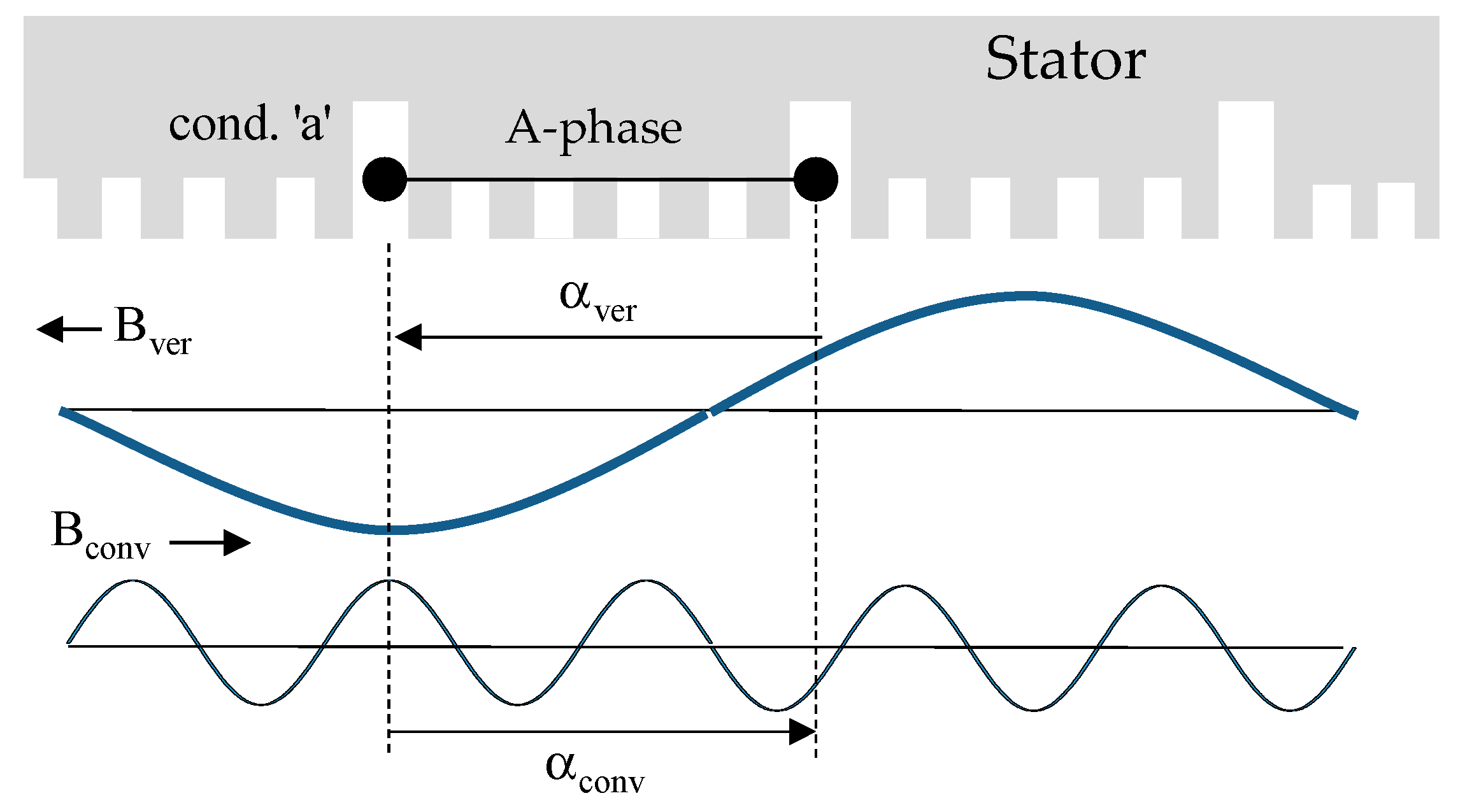
3.1. Necessary Condition for Vernier Effects Utilization
As mentioned with (7), there are both flux waves in the air gap. Thus, so as to obtain higher back EMF, both back EMFs from B
conv and B
ver need to be additive. To find the condition for this operation, it is convenient to check the induced voltage of conductor ‘a’ at the position of θ = 0 and at the instance of θ
m = 0, since the both fluxes have their (+) and (−) peak values (
and −
) as explained already with (8). By using the principle that the induced voltage of a conductor e = vB, where v is the relative speed of B to the conductor. Since the relative speeds of the waves are given as v
conv = −r
gω
m and v
ver = −r
g p
m/(p
m − Q
fmp)∙ω
m, the instantaneous voltage e
a in the conductor with unit length is given by (9).
where r
g is the air gap radius and G
r = −p
m/(p
m − Q
fmp) which is the so-called gear ratio [
9] which contributes higher back EMF of vernier PM machines than conventional PM machines.
From (9), it is clear that both EMFs are additive and the magnitude of e
a is maximized when G
r > 0 alternatively, Q
fmp − p
m > 0. Therefore, the relation Q
fmp − p
m > 0 is the necessary condition to effectively utilize the back EMF due to B
ver, which also indicates both waves need to move in opposite direction each other. Meanwhile, this condition is obtained from only one conductor ‘a’ in
Figure 1, so it is also necessary to check whether the EMFs of other conductors still additive under the condition. It can be proved by investigating the slot angle which are the angles between both adjacent slots for B
conv and B
ver.
Figure 2 demonstrates the slot angles α
conv and α
ver for the both flux waves. The angle α
conv for B
conv with p
m poles can be easily represented as (10). On the other hand, the angle α
ver for B
ver with p
ver = |p
m − Q
fmp| should be obtained with consideration of its opposite traveling direction to B
conv, and can finally be obtained as (11) by using relation Q
fmp = n
auxQ
s.
From (10) and (11), it is clear the both angles α
conv and α
ver are always same under the necessary condition Q
fmp − p
m > 0 and thus the back EMFs are additive for every conductor. It reveals another interesting fact that most of FSCW-PM machines considered as general PM motors can be classified as vernier machines. For example, the machines with the very popular ratios of three slots/two magnet poles and three slots/four magnet poles are commonly considered as general FSCW-PM machines. Therefore, in most previous references or textbooks, the characteristics of these machines are explained with only the conventional PM flux (which is B
conv in this study) without considering the modulation flux, consequently there was no difference in the fundamental magnitudes of the back EMFs of both machines [
12,
13,
14]. However, the slot pole combinations of the machines satisfy the necessary condition Q
fmp − p
m > 0 where Q
fmp are both 3 because of n
aux = 1, and p
m are 1 and 2, respectively, which means they possess the modulation flux as well as conventional PM flux. Thus, they can be classified as vernier machines in a special case of
n = 1, and it is necessary to consider the modulation flux effects on the back EMF of the machines which will be investigated in the chapter IV of this paper.
3.2. Derivation of Design Criteria for Various Auxiliary Poles
Based on the obtained necessary condition, the complete criteria for the slot–pole combinations of FSCW-PM vernier machines are proposed. To this end, the slot angle α
conv(=α
ver) for the flux B
conv is assumed to be 2π/3 or 4π/3(=−2π/3) which are the most popular winding configurations since it has one slot coil pitch. With these angles, the minimum number of the slots for a complete machine is three. If the criteria are developed for three slots (Q
s = 3), they are easily expanded to the machines whose slot number is q multiple of three. For the structure with n
aux auxiliary poles in
Figure 1, the angle α
ver of (10) can be given as (12) by using Q
s = Q
fmp/n.
where n = 1, 2, 3, … , and k = 0, ±1, ±2, ±3, ...
By solving (12) for pm, the complete criteria for the combinations of the FSCW vernier machines with the slot angle of ±2π/3 are obtained as (13). It should be mentioned that the obtained criteria can be used without considering the winding pole pair pw in conventional rule, pm − Qfmp= −pw.
For the various auxiliary poles of n
aux = 1~3, every available number of p
m for a FSCW-PM vernier machine with three slots (Q
s = 3) are acquired by using (13), resulting in 12 combinations in total. They are listed in
Table 1 with additional parameters such as p
ver and G
r. These combinations can be compared with the combinations from previous rules. If the previous rule p
m = Q
fmp − p
w = n
auxQ
s − p
w is used with the assumption of p
w = 1 for three slots (Q
s = 3), only three combinations can be obtained for same n
aux = 1~3, which are p
m = 2, 5, 8, respectively. It means the proposed method widens the range of choice of slot–pole combinations, and helps to check the existence of the vernier effects in any PM machine.
Besides, as expected in the last section, the models with p
m = 1 and 2 are included for n
aux = 1 in
Table 1 as vernier structures. In fact, there is a reason why they have not been considered as vernier machines so far. It is that the vernier effects in the both models are not significant, which can be explained as follows. Since P
0 is certainly larger than P
1 in (3), it is apparent that
is quite greater than
from (7), and thus the significance of vernier effects in the total back EMF depends on the gear ratio G
r in (8). In this respect, the values of G
r of the both models in the
Table 1 are relatively small at 1/2 and 2 respectively, and thus
is still dominant rather than G
r in (8). With the same reason, the models with p
m = 5 for n
aux = 2 and p
m = 8 for n
aux = 3 whose G
r values are 5 and 8 respectively are expected to produce quite higher back EMF comparing to the model with p
m = 1 for n = 1.
4. Analytical Calculation of Vernier Effects and Verifications through FE-Simulations
To check vernier effects on the back EMF of the obtained models, the back EMF of each models in
Table 1 are analytically calculated with analytical method, and then the analytical calculation results are compared with FE-simulation results. To this end, firstly, the geometries of the analysis models are assumed to have common specifications in
Table 2. Every model has the same air gap radius r
g, the air gap length g
a, the same PM thickness g
m and the same stack length l
stk, which keeps the magnetic loading same for each models. The ferrite magnet is assumed for the PM whose B
r is 0.4T. The slot open ratio c
0 of, in particular, is set to 0.5 because the vernier effects tend to be maximized at the value according to previous studies [
2,
3]. To keep the same electric loading, every model has the same number of series-turns/phase N
ph, and the same current is applied. With these conditions, the back EMF of each model is finally calculated at 500rpm of rotational speed.
4.1. Analytical Calculations of Back EMF using a Single Conductor Voltage
In order to calculate the back EMF, the coefficients P
0, P
1, and β for the given geometries are firstly investigated by using (4) and (5) with the number of auxiliary poles, n
aux as shown in
Figure 3, where it should be noted that P
0, P
1, and β are independent with the number of magnet pole pairs, p
m. It illustrates as n
aux increases, the coefficient β decreases because the slot opening o decreases with n
aux while the gap is kept constant as represented in (6). From (4) and (5), it is natural that the tendencies of specific permeance, P
0 and P
1, in
Figure 3b are opposite each other. With the obtained P
0 and P
1, the both peak flux densities
and
are calculated by using (7) for the combinations in
Table 1. Using (8), the induced voltages
and
due to both flux densities
and
and their sum, that is, the peak induced voltage
of the conductor ‘a’ is calculated at 500 rpm in which the factor G
r in
Table 1 is used.
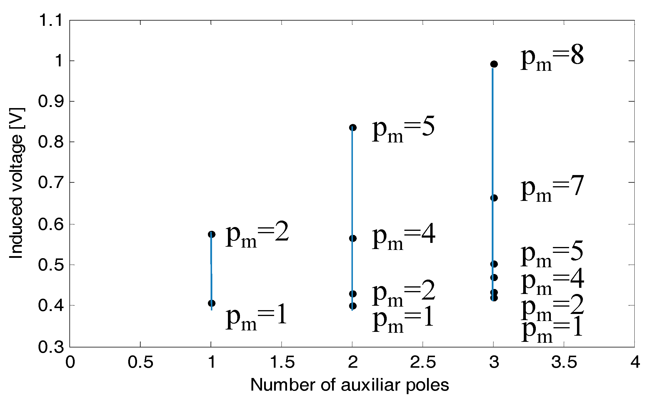
The calculated results through the procedure explained above are listed in
Table 3. In case of n
aux = 1, two models with p
m = 1 and 2 have the same voltage from general PM flux. On the other hand, their voltages due to vernier effects are quite different, and thus the model with p
m = 2 has higher back EMF than the one with p
m = 1. Consequently, it is necessary to consider the vernier effects in the calculation of back EMF of the model with the ratio of three slots/four magnet poles even though the voltage from common PM flux is still dominant. Among the models in
Table 2, two models with p
m = 5 of n
aux = 2 and p
m = 8 of n
aux = 3 have higher voltage from modulation flux than that from conventional PM flux, resulting in substantially higher net back EMF than other ones. In particular, the model with p
m = 8 for n
aux = 3 is almost 2.5 times the back EMF of the model with p
m = 1 at n
aux = 1.
From the results of
Table 3, it can be summarized that the EMFs from modulation flux as well as conventional PM flux increases with increase of n
aux. The model with G
r less than 2 has negligible vernier effects which are those with p
m = 1 of n
aux = 1, p
m = 1 and 2 of n
aux = 2, and p
m = 1, 2, 4, and 5 of n
aux = 3 while others show meaningful vernier effects in the back EMF. For convenient comparison, the back EMF results in
Table 3 are plotted in
Figure 4.
Using the back EMF
of a single conductor in
Table 3 and
Figure 4, the back EMF in phase winding of each model can be easily calculated with (14) considering the winding factor due to the slot angle of ±2/3π which will be compared with FE simulation results in the next section.
4.2. Models for Finite Element Analysis and Simulation Results
Among the models in
Table 3, five models in total are chosen for FE-analysis, and their detailed specifications are same as provided in
Table 2. Two of them are the machines with p
m = 1 and 2 of n
aux = 1 which are chosen to confirm the vernier effects of the one with p
m = 2 since they have been commonly considered as conventional machines. In other words, their back EMFs should be same according to the classical machine theory, but will be different according to the results in
Table 3. The other three models with p
m = 5 of n
aux = 2, and p
m = 7 and 8 of n
aux = 3 are chosen to verify the substantial back EMF boost effects. The stators of analysis models with n
aux = 1, 2, and 3 are shown in
Figure 5, respectively where the slot open ratio of each model is 0.5. In addition, the thickness of the back yoke is determined considering flux per pole, so it is thinner as n
aux increases, which partially compensates the reduced slot area of the model with high n
aux.
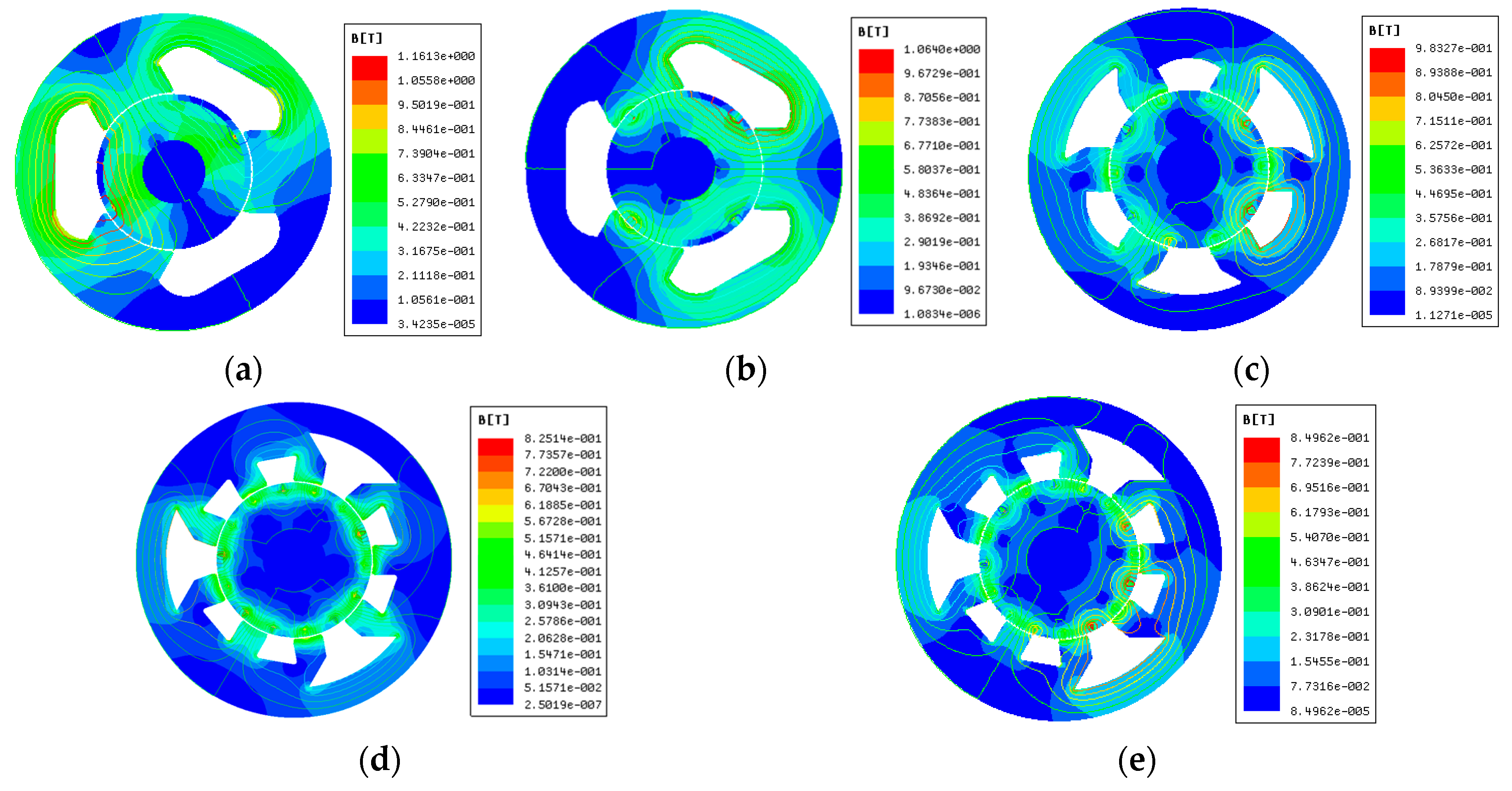
For the analysis models with the stators in
Figure 5 and the rotors having different p
m, the flux density and equipotential lines are solved with FEM and presented in
Figure 6. It describes that the flux density of core and teeth is around 0.4~0.7 T, so there is no concern about saturation effects.
Under the established simulations conditions, the no-load back EMF of the analysis models at 500rpm are analyzed and the back EMF waveforms are plotted in
Figure 7a. It shows that the model with p
m = 8 develops the highest back EMF, the next is the model with p
m = 5, and the last is the model with p
m = 1. Especially, the model with p
m = 1 has apparently less back EMF than the model with p
m = 2, clearly demonstrating the existence of vernier effects on the back EMF. The magnitudes of the first harmonics of the back EMF waveforms in
Figure 7a are obtained by discrete Fourier expansion and compared with the back EMFs analytically calculated from (14) in
Figure 7b. It shows that both results are in good accordance whose difference is less than 5%. Consequently, it can be said that every model found by using the proposed method includes vernier effects, even though the effects of first one (p
m = 1) with G
r = 1/2 are very negligible.
In addition, the characteristics of torque are calculated for the analysis models. FE-simulations are carried out with the phase current 2A (RMS) in phase with the back EMF, and the simulation results are depicted in
Figure 8. It shows that the model with p
m = 8 of n
aux = 3 is about 2.5 times torque of the model with p
m = 1 of n
aux = 1, and overall characteristics coincide well with the back EMF results, which supports validity of the proposed assertion and effectively describes the advantage of vernier machines with higher power density. It is also can be seen that the torque ripple characteristics are getting better with the increasing number of PMs.
5. Conclusions
In this study, to improve the theoretical uncertainty and restrictions in case that the previous design rule is applied to the machines with slot-concentrated windings, the necessary condition for effective utilization of vernier effects, Qfmp > pm, is firstly obtained, and then under the condition, the new criteria for slot–pole combinations were proposed for the most popular case of slot angle of ±2/3π in the expression of well-organized form. It should be noted that the winding pole pairs, pw of the FSPM machine is not necessary in the proposed criteria. Using the proposed criteria, every structure having vernier effects was found for a base FSCW PM machine with three stator slots and various auxiliary poles naux.
The investigation of the obtained FSCW-PM vernier machines are summarized as follows. First, in the obtained structures, many others are included which couldn’t be found with the previous rules, which shows the versatility of the proposed criteria. Notably, it is shown that the PM machines with the slot/pole ratios of 3/2 and 3/4 are also included which have been considered as general ones without vernier effects. In addition, the model with pm = 7 of naux = 3 is newly found and has quite big vernier effects which is hardly found by the previous design rule.
Using the obtained slot–pole combinations, practical FSCW-PM machines are designed with the same electric and magnetic loadings. The analytical calculations and FE analysis for the back EMF of the models are performed, and both results are in good accordance, indicating the usefulness of the air gap specific permeance functions expressed in terms of machine geometries. From the calculation results, it was proven that the obtained models from the proposed method have the vernier effect as expected, and the effects are dependent on the slot pole combinations. As expected, the model with three slots/four PM poles has higher back EMF than that with three slots/two PM poles due to higher gear ratio Gr. Therefore, it is necessary to consider the vernier effects in the accurate expression of performance characteristics such as the back EMF of those machines. The torque characteristics obtained through FE simulations presents good agreement with back EMF results, describing that the vernier motors have much higher power density than conventional PM machines. Finally, it can be said that the proposed method can be used in search for more candidates of PM vernier machines, and helps to make decisions about the best slot–pole combination in various conditions.


