Article

Sensitivity Analysis of Heavy Fuel Oil Spray and Combustion under Low-Speed Marine Engine-Like Conditions

State Key Laboratory of Engines, Tianjin University, 92 Weijin Road, Nankai District, Tianjin 300072, China
*
Author to whom correspondence should be addressed.
These authors contributed equally to this work and should be considered co-first authors.
Energies 2017, 10(8), 1223; https://doi.org/10.3390/en10081223
Submission received: 2 August 2017 / Revised: 8 August 2017 / Accepted: 9 August 2017 / Published: 17 August 2017
(This article belongs to the Section F: Electrical Engineering)

Abstract

:
On account of their high power, thermal efficiency, good reliability, safety, and durability, low-speed two-stroke marine diesel engines are used as the main drive devices for large fuel and cargo ships. Most marine engines use heavy fuel oil (HFO) as the primary fuel, however, the physical and chemical characteristics of HFO are not clear because of its complex thermophysical properties. The present study was conducted to investigate the effects of fuel properties on the spray and combustion characteristics under two-stroke marine engine-like conditions via a sensitivity analysis. The sensitivity analysis of fuel properties for non-reacting and reacting simulations are conducted by comparing two fuels having different physical properties, such as fuel density, dynamic viscosity, critical temperature, and surface tension. The performances of the fuels are comprehensively studied under different ambient pressures, ambient temperatures, fuel temperatures, and swirl flow conditions. From the results of non-reacting simulations of HFO and diesel fuel properties in a constant volume combustion chamber, it can be found that the increase of the ambient pressure promotes fuel evaporation, resulting in a reduction in the steady liquid penetration of both diesel and HFO; however, the difference in the vapor penetrations of HFO and diesel reduces. Increasing the swirl flow significantly influences the atomization of both HFO and diesel, especially the liquid distribution of diesel. It is also found that the ambient temperature and fuel temperature have the negative effects on Sauter mean diameter (SMD) distribution. For low-speed marine engines, the combustion performance of HFO is not sensitive to activation energy in a certain range of activation energy. At higher engine speed, the difference in the effects of different activation energies on the in-cylinder pressure increases. The swirl flow in the cylinder can significantly promote fuel evaporation and reduce soot production.

1. Introduction

Low-speed two-stroke diesel engines with a large piston bowl are mainly used in marine applications; these engines are undergoing rapid development [1,2,3]. The main fuels used in two-stroke marine engines are heavy fuel oil (HFO) at sea and diesel along the coastline [4,5]. However, the International Maritime Organization (IMO) has enforced the Tier III limit regulation in 2016 [6]. According to this regulation, the NOx emissions of marine engines operating along the coastline is to be reduced [7]. No limits have been specified yet for carbon emissions and particulate matter, but they would also be restricted in the near future [8,9]. Therefore, it is necessary to study the spray, combustion, and emission characteristics of HFO.
Although HFO is widely used in marine engines at present, few experiments have been performed on HFO sprays until now. Herrmann et al. [10,11,12] studied the penetration lengths of HFO under different conditions, such as pressure, swirl intensity, and air temperature in a constant volume combustion chamber. Takasaki et al. [13] studied the combustion characteristics of HFO in a visual steady flow constant volume combustion chamber (SFCVCC). The experimental data presented in this study were applied in the present work. Struckmeier et al. [14] also performed experiments on combustion of HFO using a fuel ignitability analyzer (FIA). Hult et al. [15] studied the penetration lengths and ignition characteristics of HFO; the experiment was conducted using the cylinder of a marine engine. Compared with marine gas oil, HFO increases the width of the end of the spray and a more wrinkled appearance. Anderson et al. studied the particulate matter (PM) emission from HFO [16] using a marine engine operating at low loads. Further, there are some other studies on the combustion and emissions performance of HFO, and comparison of the properties of HFO with those of other biodiesels [17,18].
Marine diesel engine experiments are very expensive to perform and provide limited information, and hence computational fluid dynamics (CFD), which is an efficient analysis tool, has become a preferred tool for comprehensively understanding the fuel spray and combustion processes under marine engine-like conditions. Several HFO spray simulations have been performed in previous studies. Goldsworthy [2] considered HFO as the combination of a residual base and a light component. Two important parameters, ignition delay factor and activation energy, were studied in a constant volume vessel chamber. One of the results agreed well with the experimental data. Struckmeier et al. [19] introduced two-component droplet evaporation into Goldsworthy’s model and obtained better results. Kyriakides et al. [20] further studied the HFO model and refined the residual fuel properties. Stamoudis et al. [21] applied the characteristic time combustion model to study the combustion of HFO; the heat release rates (HRRs) of diesel and HFO were obtained using an FIA. Chryssakis et al. studied the effects of introduction of water in a large two-stroke marine engine fueled with C14H30 at full load using CFD [22].
Overall, it can be concluded that fuel properties and combustion characteristics of realistic heavy fuel oil (RHFO) are very complex. However, there are only limited studies on the sensitivity analysis of the thermophysical properties of the fuel used in marine engines, such as fuel density, dynamic viscosity, critical temperature, and surface tension.
The objective of this work was to conduct parameter sensitivity studies based on numerical simulations for HFO spray, combustion, and emissions, and compare the results with experimental data. In this work, the thermophysical properties of the fuel are adopted from those of HFO and diesel. Diesel represents a light component and HFO represents a heavy component in the RHFO. The present work demonstrates the following new contributions: (1) the comparison of spray characteristics between HFO and diesel fuels is carried out under different ambient pressures, ambient temperatures, fuel temperatures, and swirl conditions; (2) the effects of activation energy on the performance of the marine engine at different speeds based on different spray characteristics, and the effects of swirl ratio on the marine engine fueled with HFO are studied. The results of the present work on fuel sensitivity analysis will give a new insight into the characteristics of HFO used in marine engines.
In the remainder of this paper the spray and combustion models are described in Section 2. The conditions for numerical computations are described in Section 3. The effects of different parameters on HFO and diesel spray, combustion, and emission performance are described in Section 4. Finally, the conclusions are presented in Section 5.

2. Numerical Models

2.1. Spray Model

The Kelvin-Helmhotlz and Rayleigh-Taylor (KH-RT) model [23] is used to predict the droplet breakup process; it is derived from the wave model. The wave model considers only the stripping process of the droplets due to the growth of Kelvin-Helmholtz instabilities on the droplet surface, which results from the relative velocity between the gas and the liquid phase; the prediction accuracy is enhanced by adding the Rayleigh-Taylor (RT) model to account for the sudden catastrophic breakup due to the deceleration of the droplets [24]. Within the characteristic breakup distance L b , only KH instabilities cause breakup of the droplets. Beyond the characteristic breakup distance, both KH and RT mechanisms are activated. L b is defined as:
L b   =   C b l d 0 ρ l ρ g
where C b l is a constant, and its value is taken as 30; d 0 is the nozzle diameter. In this case, the KH-RT model first checks if the RT mechanism can break up the droplets. If the RT mechanism cannot break up the droplets, the KH mechanism causes the breakup.

2.2. Combustion Model

2.2.1. Shell Model

Unlike in gasoline engines, chemical reactions of the fuel lead to ignition in diesel engines. Ignition delay occurs at certain crank angle, which may be several degrees. Once ignition occurs, the fuel-air mixture induces the premixed combustion phase, and then mixture-controlled combustion occurs. To simulate the ignition process, the Shell model is used. This model is based on simplified reaction mechanisms, which include eight-step chain reactions and tested qualitatively against experimental. In the Shell model, the constant A f 04 is a sensitive value that can control the ignition time. In this study, the value of A f 04 is taken as 1.2 × 10⁵.

2.2.2. CTC Model

The combustion process is simulated with the characteristic time combustion (CTC) model. The CTC model, which was originally adopted to predict diesel combustion by Kong and Reitz [25], is used in this work. It simulates the rate of change of the density of the species:
d ρ m d t = ρ m ρ m τ c h e m + f τ t u r b
where ρm is the local and instantaneous thermodynamic equilibrium value of the species density, τ c h e m is the chemical kinetics time, τ t u r b is the turbulent mixing time, and f is the delay coefficient, which is an indication of the effects of turbulence. The laminar timescale and turbulent mixing timescale are derived from the correlated one-step reaction rate.
τ c h e m = [ C n H 2 m ] 0.75 e ( E c h e m R u T g ) 2 A c h e m [ O 2 ] 1.5
τ t u r b = C m 2 k ε
In the above equation, E c h e m is the activation energy. R u is the universal gas constant and T g is the gas temperature. The term C m 2 represents the turbulent timescale constant; its value is taken as 0.2.

3. Conditions for Numerical Computations

In this study, two different experiments on HFO characteristics were performed. The experimental data are taken from the studies conducted by Herrmann et al. [10,11,12]. The experimental apparatus used is a rotational flow constant volume combustion chamber (RFCVCC). The diameter and height of the device are 500 mm and 150 mm, respectively. The gas composition used in the study is N2. The injected fuels are HFO and diesel. The details of the structure are shown in Figure 1.
The experimental data on combustion are taken from the studies conducted by Strom and Struckmeier et al. [21]. The experimental device used in this study is an FIA, which is employed to validate the HFO combustion model. The diameter and height of the device are 190 mm and 65 mm, respectively. A single hole nozzle injector mounted on the top of the combustion chamber is modified. The injection pressure is 55 MPa, and the injection duration is 20 ms. The conditions of the experiments conducted using the RFCVCC and FIA are listed in Table 1. It should be noted that the ambient temperature and ambient pressure indicate that initial temperature and pressure in confined combustion chamber, which is much higher than room temperature.
The simulations are performed on a uniflow scavenged two-stroke, low-speed marine engine with a large piston bowl. The detailed engine specifications and configurations are presented in Table 2. The cylinder has two injectors, located symmetrically on the periphery of the cylinder head in the co-swirl direction. The scavenge box has almost no effect on the simulation of the marine engine, and hence it is omitted to save simulation time; this can be seen in Figure 1.
In the present work, the HFO is considered as a single component. The typical thermophysical properties of HFO, such as dynamic viscosity, vapor pressure, surface tension, and heat of evaporation are shown in Figure 2; these data are as the study conducted by Kyriakides [20], and are compared with properties of diesel fuel. The conductivity of HFO is the same as that of diesel. The critical temperature of HFO is 928 K, which is evaluated by the correlation [26]. The liquid density of HFO is 953.7 kg/m3, and is assumed to be constant. The critical temperature of diesel is 736 K; the density is 848 kg/m3, and is assumed to be constant.
The simulations were conducted in CONVERGE 2.3. The KH-RT model is used to predict the breakup process of the droplets. The rebound-slide model is used for spray-wall interaction [27]. The NTC method [28] is adopted for droplet collision modeling. The Frossling model is used to predict the droplet evaporation process. The re-normalization group (RNG) k-ε model is adopted as the turbulence model. The Shell/CTC combustion model is used to predict the heat release rate. The Hiroyasu [29] soot model and the Zeldovich NOx model are used to predict the emissions. The base cell size of the RFCVCC and FIA models is 2 mm. The base cell size of the 340 marine engine model is 4 mm. An adaptive mesh refinement (AMR) algorithm is employed to automatically refine the grid based on species, temperature, and velocity. The minimum grid size of the FIA and RFCVCC models is 1 mm. The minimum grid size of the 340 marine engine model is 2 mm. The maximum number of grids in the RFCVCC, FIA, and 340 marine engine models are 7 × 10⁵, 1.2 × 10⁶, and 2 × 10⁶, respectively. Variable time-step algorithm is used in the simulation; the initial time step is 1 × 10⁻⁷, the maximum time step is 1 × 10⁻⁴, and the minimum time step is 1 × 10⁻⁸.

4. Results and Discussion

The experimental data from the RFCVCC and FIA are employed to conduct sensitivity analysis of the fuel spray process and validate the present model qualitatively. In addition, the effects of different ambient parameters on HFO and diesel spray processes are investigated.

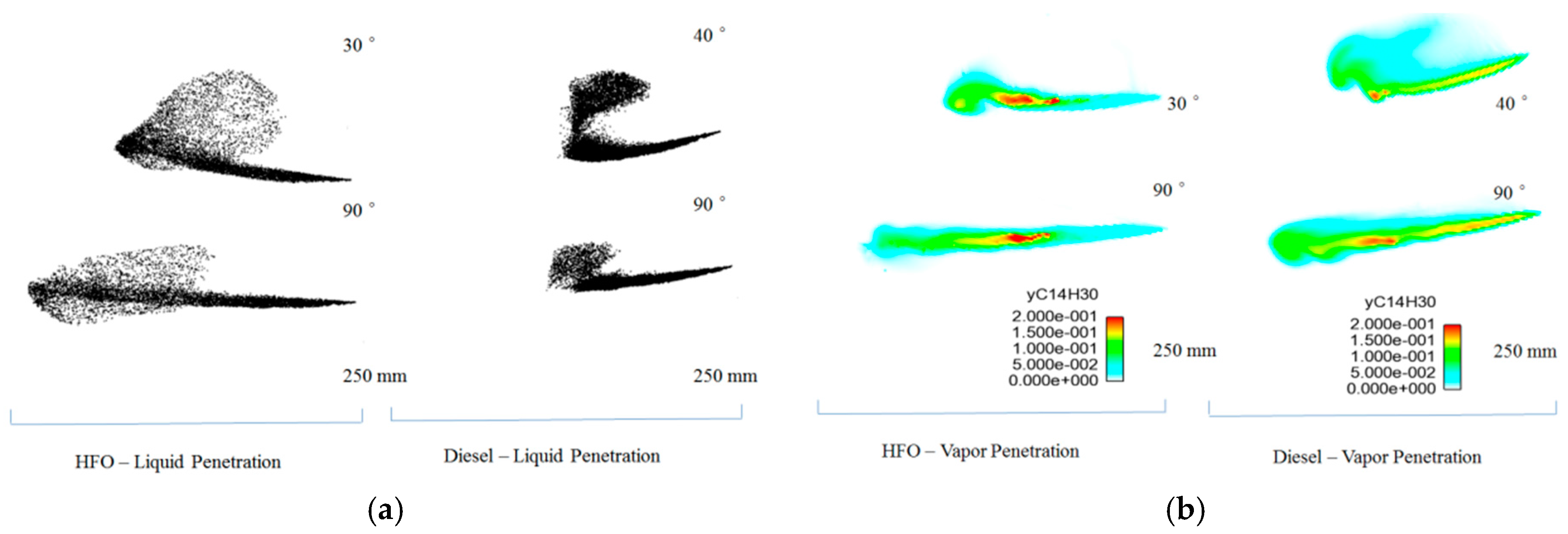
4.1. Non-Reacting Simulations

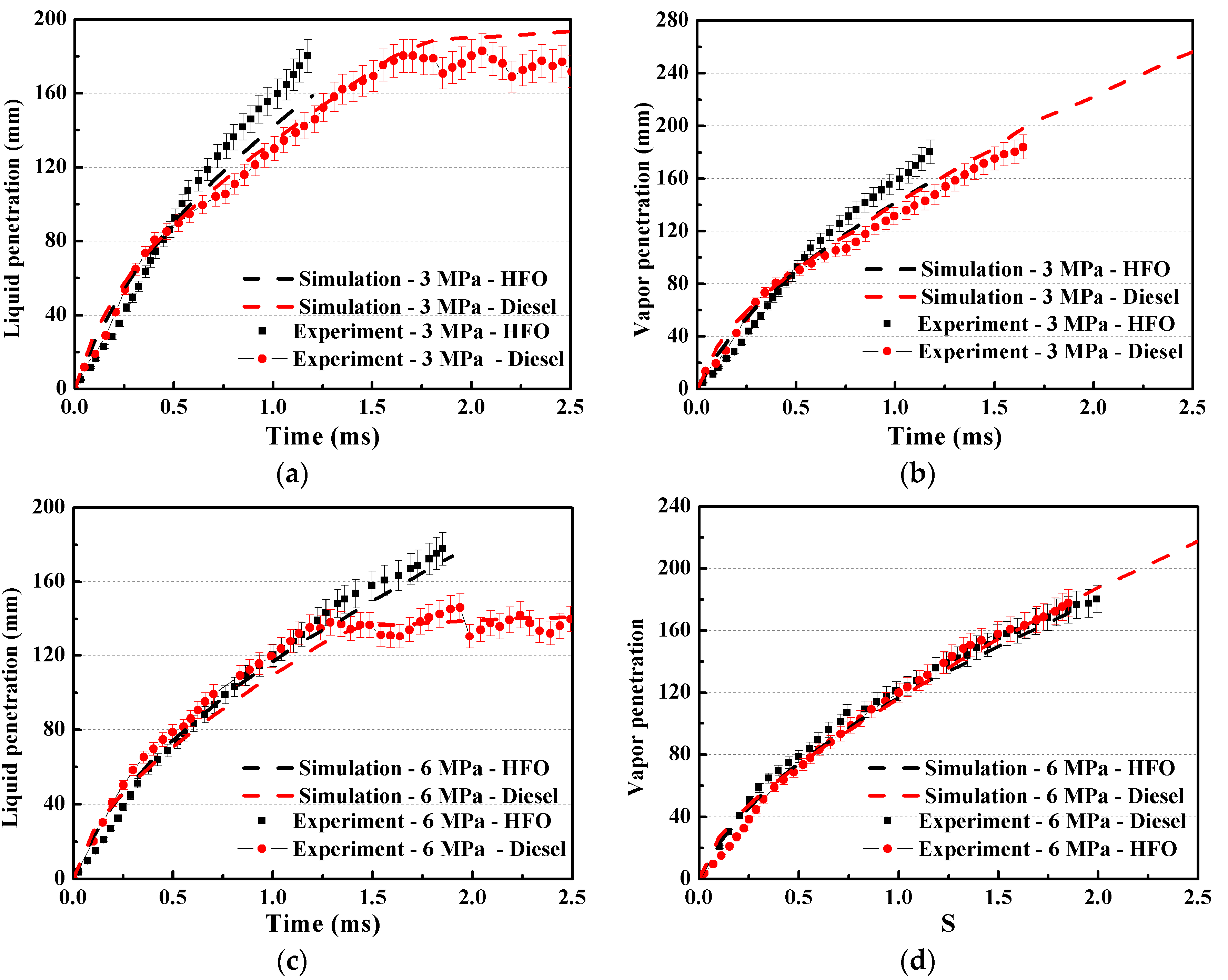
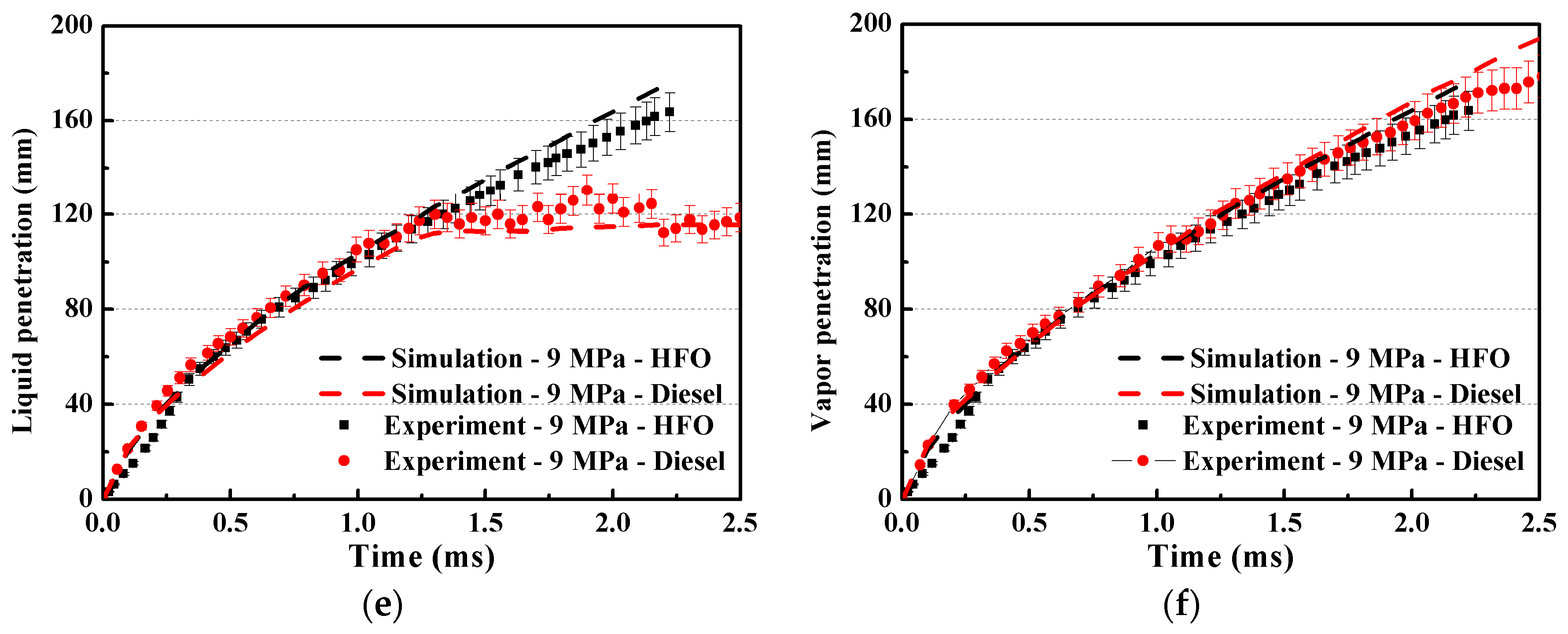
4.1.1. Spray Characteristics at Different Ambient Pressures

The non-reacting simulations of fuel spray for HFO and diesel are studied. The liquid and vapor penetrations, obtained from simulation and experiment at 900 K of ambient temperature and 9 MPa of ambient pressure, 6 MPa of ambient pressure, and 3 MPa of ambient pressure, are compared. As shown in Figure 3, the experimental data and predicted data fit well with the error tolerance of 5%. Note that, in Figure 3 only liquid penetration of HFO has a little deviation from experiment data at 3 MPa of ambient pressure. The liquid penetration of HFO is higher than that of diesel. The main reason may be that the density and critical temperature of HFO are higher. With the decrease in the ambient pressure, the interactions between the gas and liquid droplets are weakened and the separation time is delayed, and the steady penetration length increases from around 120 mm at 9 MPa of ambient pressure to around 180 mm at 3 MPa of ambient pressure. It is also found that the liquid spray penetration length of HFO is nearly the same as the vapor spray penetration length, because of the high critical temperature of HFO. Furthermore, the vapor penetrations are obtained from simulations agree well with the test data. Thus, it can be concluded that for vapor phase penetration, increasing the ambient pressure promotes fuel evaporation. There is no significant difference in penetration between HFO and diesel.

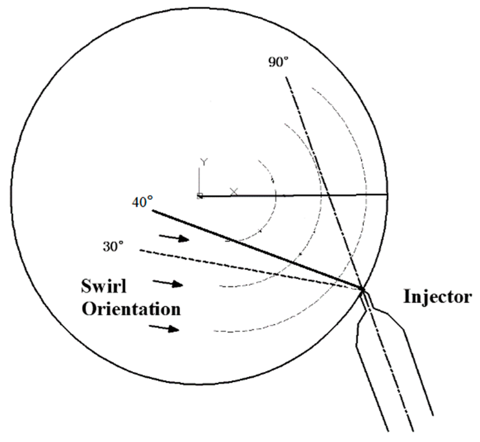
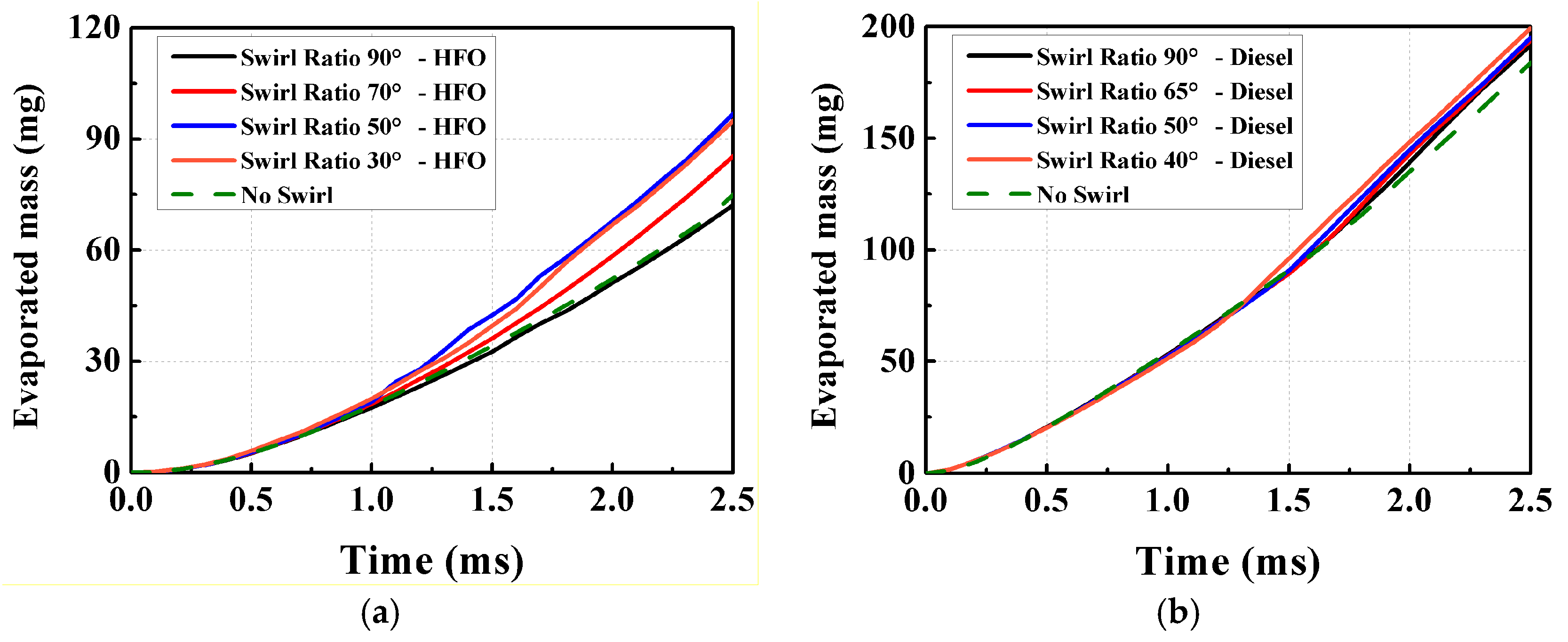
4.1.2. Spray Characteristics at Different Swirl Ratios

The effect of swirl on HFO and diesel spray characteristics including liquid spray penetration and vapor penetration are studied, and the results are shown in Figure 4. To obtain the effects of different swirl conditions, different injection angles or spray orientations are adopted. Two injection angles, 30° and 90°, are compared in the studies on HFO, as against the 40° and 90° in the studies on diesel.
The injection angles are shown in Figure 5. The results show that a small injection angle suppresses spray penetration, which enhances gas-liquid two-phase interaction, promotes evaporation, and reduces the droplet size. When the injection angle is 30° or 40°, the spray direction is opposite to the direction of the swirl. As a result, the swirl exerts a force opposite to the droplet moving direction. In addition, the droplet is blown toward the direction of the swirl, which reduces spray penetration. Because of the different evaporation features of the fuels, diesel is more influenced by swirl flow. It can be seen that increasing the injection angle (or reducing the swirl) reduces the force on the spray, especially in the case of diesel. However, the swirl has almost no influence on the evaporations of HFO and diesel fuels, and there is no significant difference in the vapor penetrations of these fuels. Figure 6 shows the evolutions of evaporated mass of HFO and diesel fuels for different spray orientations. Similar to the results as shown in Figure 4, the swirl flow enhances the liquid-gas interactions and promotes the evaporation. It can be found that increasing the interactions by changing the spray orientation can increase evaporated mass. Furthermore, the effect of the swirl flow on the HFO fuel is more obvious than diesel fuel.

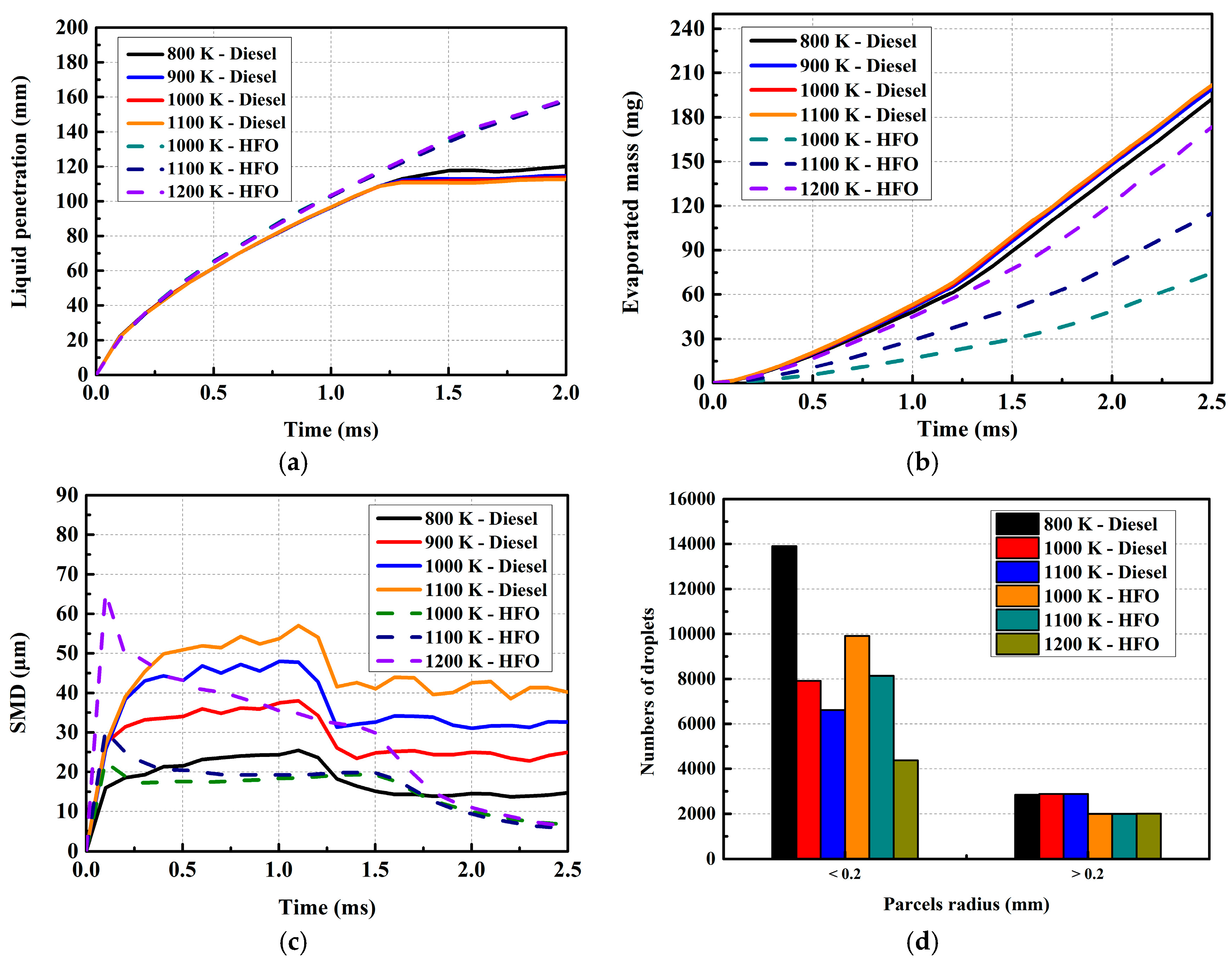
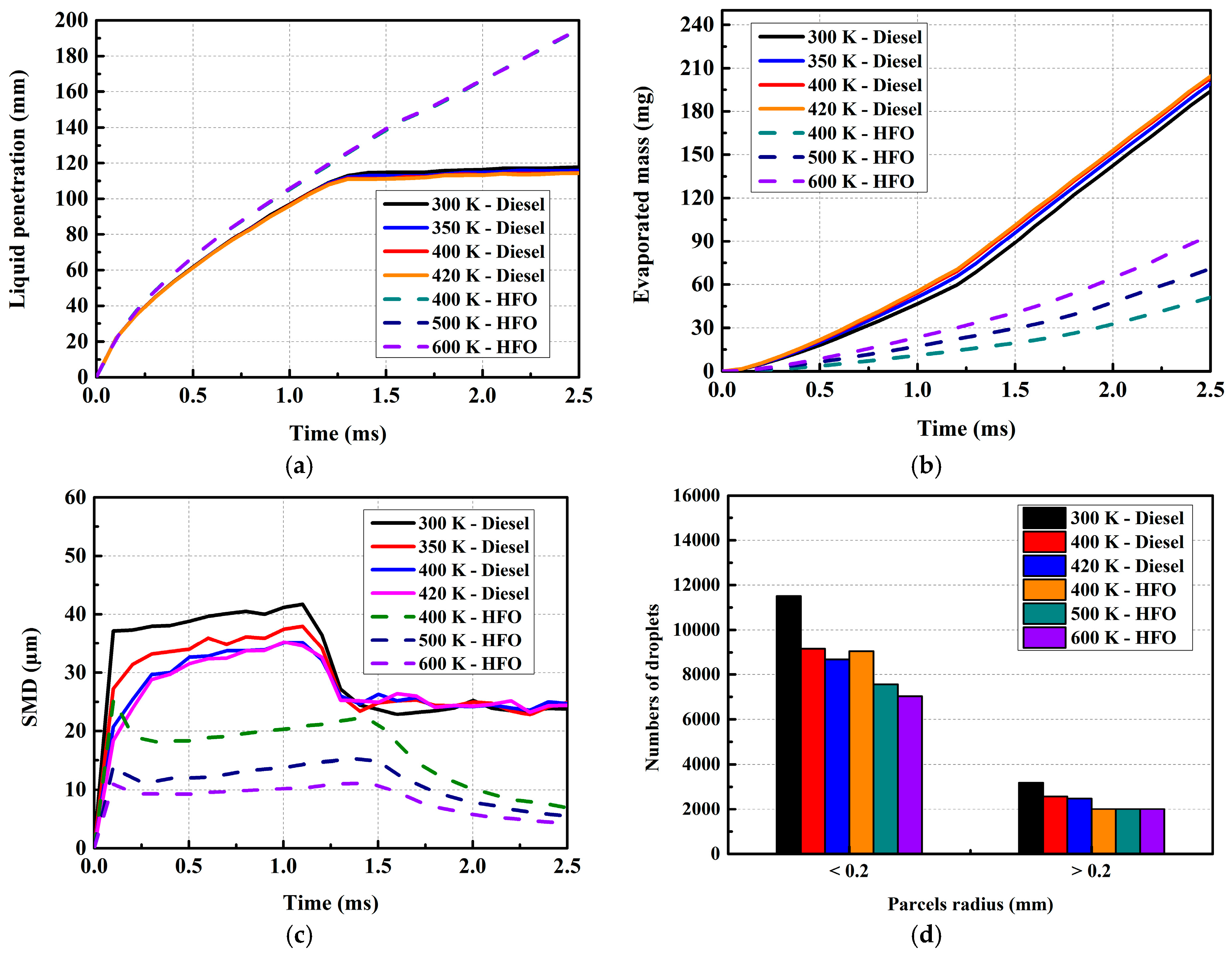
4.1.3. Spray Characteristics at Different Ambient Temperatures and Fuel Temperatures

The effect of ambient temperature and fuel temperature on HFO and diesel spray characteristics, such as SMD, liquid penetration, and evaporated fuel mass are studied at 9 MPa of ambient pressure. The results are shown in Figure 7 and Figure 8. It can be seen from Figure 6a that the liquid penetrations of both HFO and diesel are not sensitive to the ambient temperature. It can be seen that the liquid penetration depends on the type of fuel. The variation in evaporated fuel mass with time is dependent on the fuel properties. As in the case of liquid penetration, the evaporation mass of diesel is not influenced by the ambient temperature in the range of 800–1100 K, as shown in Figure 7b; this is because the critical temperature of diesel is far lower than the ambient temperature. In other words, at the ambient temperature of 800 K, the temperature is high enough to promote fuel evaporation. In contrast, in the case of HFO, because of the poor evaporation performance, the evaporated full mass is significantly influenced by the ambient temperatures in the range of 1000 K to 1200 K. Increasing the ambient temperature can effectively promote the evaporation process and increase the evaporated fuel mass. It can be seen from Figure 7c that the SMD is significantly affected by the ambient temperature for HFO and diesel. It may be noted that the overall SMD size in the fuel that evaporates easily, such as diesel in present work, is larger than that in the case of HFO. Further, the SMD increases with increase in ambient temperature; the main reason is that the ambient temperature influences the sizes of the peripheral droplets of the spray, which have the smaller droplet radius. However, in the inner area and the area near the injector, the relatively larger droplets are not significantly affected. This can be explained from the results shown in Figure 7d. It can be seen from the figure that as the ambient temperature is increased, the number of droplets with small parcel radius decreases. There was no variation in the number of droplets with large parcel radius. In this study, when the droplet has a radius larger than 0.2 mm, it is classified as a large droplet, and in the other cases, it is defined as a small droplet.
Figure 8 shows the HFO and diesel spray characteristics at different fuel temperatures and at an ambient temperature of 900 K. As in the case of ambient temperature, the fuel temperature also has no influence on the liquid penetrations of HFO and diesel spray, as shown in Figure 8a. Comparing Figure 7b and Figure 8b, it can be seen that the effect of fuel temperature on the evaporated mass is less than that of ambient temperature. The fuel temperature has a significant effect only on HFO.
The variations in SMDs of diesel and HFO at different fuel temperatures are significantly different from the variations at different ambient temperatures. It can be seen that increasing the fuel temperature significantly reduces the SMD in the development stage of the spray before around 1.0 ms for diesel and 1.5 ms for HFO. The reason is that the increase in fuel temperature can promote fuel evaporation regardless of the size of the droplets, which leads to a decrease in the overall number of droplets or SMD. The distribution of droplet sizes at different fuel temperatures, shown in Figure 8d, indicates that increasing the fuel temperature reduces the overall number of droplets, including both large and small droplets, especially for diesel. In the case of HFO, as the fuel temperatures used in the present work are lower than the critical fuel temperature, the fuel temperature has only a small influence on small droplets.
In addition, because of the differences in the fuel properties, the spray processes of HFO and diesel have different characteristics under various conditions. The next section will cover the effects of fuel activation energy and engine properties on cylinder pressure, heat release rate, and NOx emissions in the marine engine.

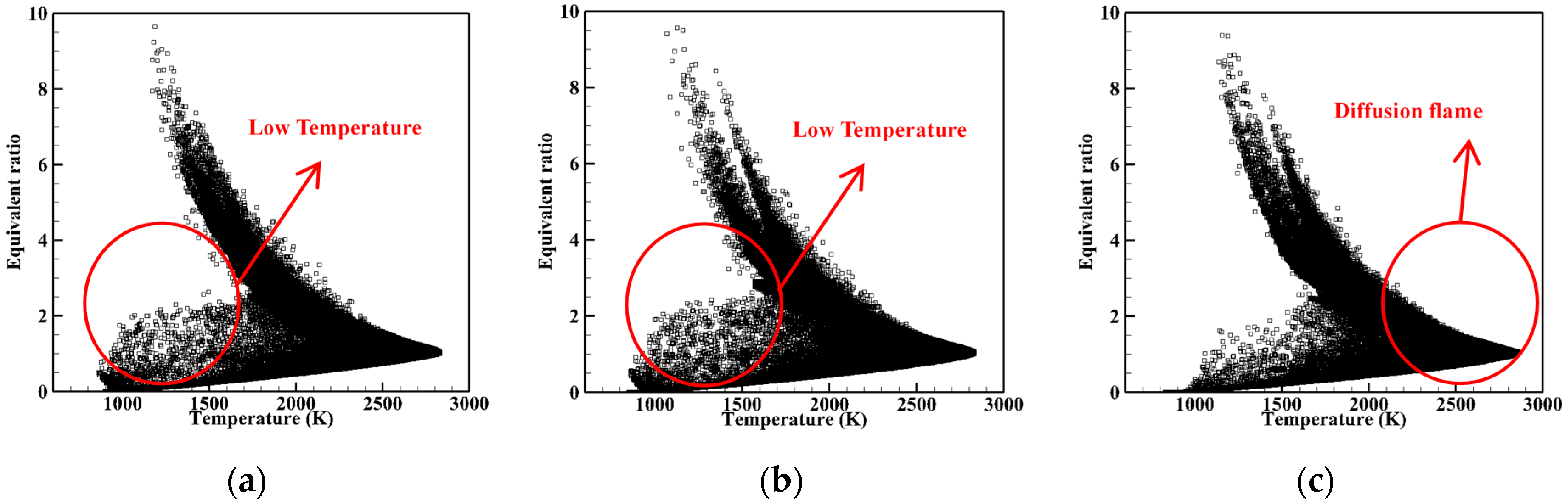
4.2. Reacting Simulations

There have been very few studies on combustion experiments using HFO. In terms of the validation of the spray models mentioned above, in this work, the heat release rate is validated based on an FIA model, and the simulation results are compared with experimental results; the details are shown in Figure 9. The activation energy of HFO, obtained from the reference, is set to approximately 95.7   kJ / mol to validate the HFO combustion. It can be seen that the simulated ignition time is a slightly less than the ignition time obtained in the experiment. The heat release rates calculated by the present models agree well with the experimental results. However, the HFO used in the experiment has a complex composition, and activation energy is one of the most important properties that influences the combustion process. To further investigate the effect of activation energy on the combustion of HFO, four activation energies are applied: 77.4 kJ/mol, 95.7 kJ/mol, 104 kJ/mol, and 129 kJ/mol. The results of simulations are shown in Figure 9. Note that, in Figure 9 the calculation of heat release rate is as below:
HRR   =   hr _ time d   ( h r ) d   t
where, hr _ time is a heat release output parameter based on the seconds or crank angle degree. d   ( h r ) represents the heat release. In addition, the calculation of activation energy Echem is expressed in Equation (3) in Section 2.
It can be seen from the figure that the change in Echem does not affect the peak of the heat release rate in a certain range, but it significantly affects the combustion phase. When the value of Echem is 129 kJ/mol, the activation energy is too large to release heat, and hence no combustion occurs in this case. As the Echem is reduced, the combustion phase is advanced, and the peak heat release rate remains constant. The HRR for the activation energy of 95.7 kJ/mol is consistent with the experimental data.

4.3. Parameter Studies in Marine Engine

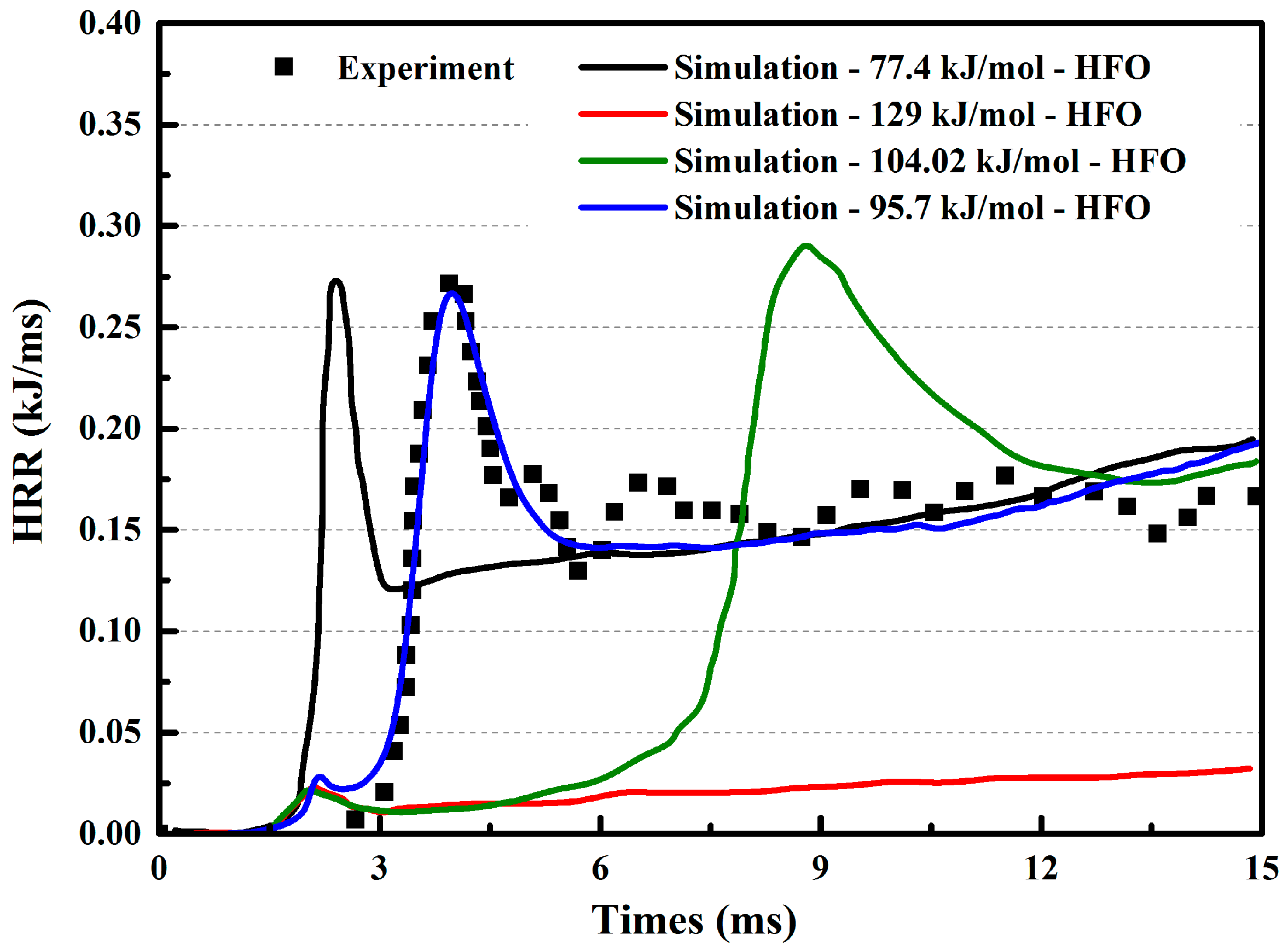
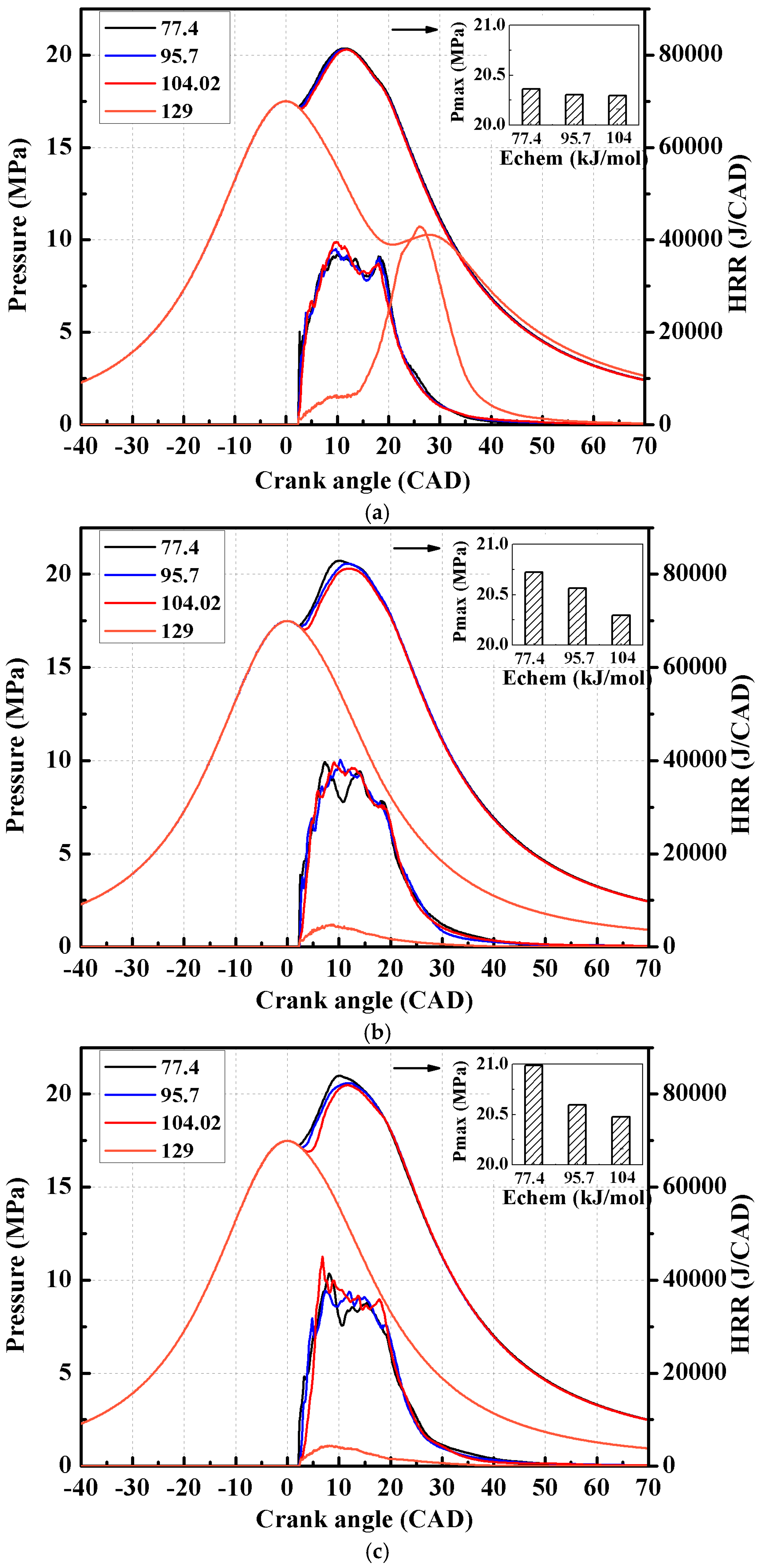
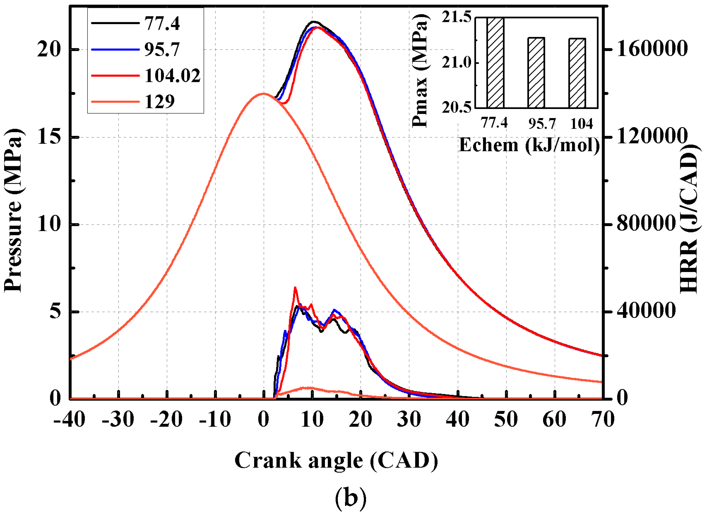
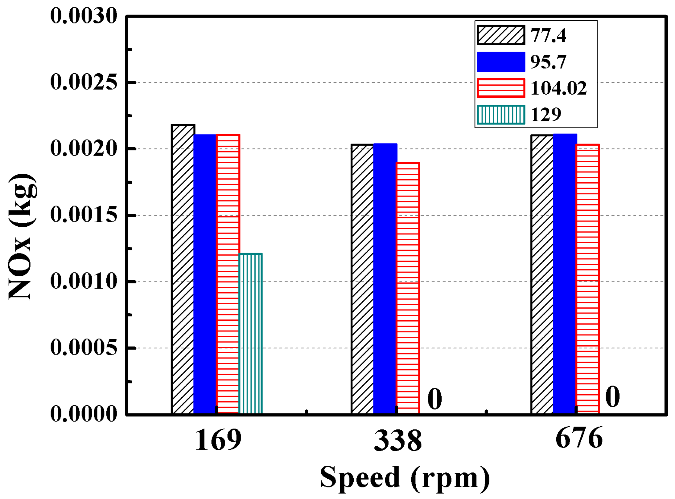
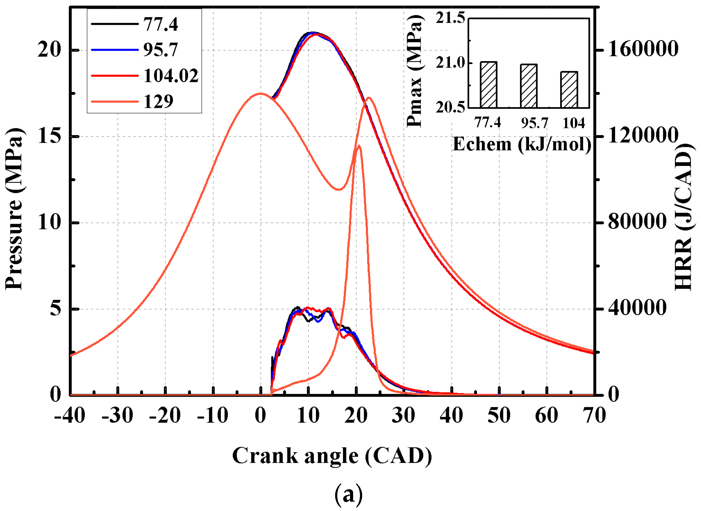
4.3.1. Effect of Activation Energy at Different Speeds

Based on the above results, the effects of activation energy on a marine engine fueled with diesel and HFO at different speeds are studied. Due to the complex composition of the heavy oil in the experiment, the thermal cracking or thermal polymerization occurs and different compositions with different energies are generated during the actual combustion process. The thermal cracking and thermal polymerization cannot be considered in the numerical calculation. To study the effect of activation energy on HFO and diesel in marine engines, four activation energies are employed: 77.4, 95.7, 104 and 129 kJ/mol based on the work [21,30]. Three engine speeds are adopted in the simulations: 169, 338 and 676 rpm. Two speeds, 169 and 676 rpm, are adopted in the marine engine simulation with diesel fuel. Note that the purpose of using different engine speeds is only to find the sensitivity of fuel activation energy under the same conditions based on different spray characteristics.
Figure 10 shows the plots of pressure, heat release rate, and NOx obtained with different activation energies at three engine speeds. As shown in Figure 10a, when the activation energy is 129 kJ/mol, the in-cylinder pressure is significantly lower than that at other activation energies; the reason is that the activation energy of 129 kJ/mol is too large to release heat at 10° CA ATDC. Similarly, with the increase in engine speed, the activation energy of 129 kJ/mol cannot release heat; this can be seen in Figure 10b,c. Further, it can be seen from the figures that the increase in activation energy does not significantly influence the in-cylinder pressure at the engine speed of 169 rpm. The maximum pressures for different activation energies are almost the same. With the increase in engine speed, the differences in the in-cylinder mean pressure and maximum pressure for different activation energies become significant. At the engine speed of 338 rpm, the maximum pressure for the activation energy of 77.4 kJ/mol is higher by around 0.4 MPa than the maximum pressure for the activation energy of 104.02 kJ/mol. As the engine speed increases to 676 rpm, the maximum pressure for the activation energy of 77.4 kJ/mol is higher by around 0.5 MPa. It can be concluded that the effect of fuel activation energy on combustion becomes more significant at higher engine speeds.
In other words, for the low-speed marine engine, the combustion performance of HFO is not sensitive to the activation energy in a certain range of activation energy, because the higher engine speed will reduce the engine cycle time and combustion duration, which results in insufficient time for burning of the fuel with high activation energy. In addition, the high-compression pressure at TDC that reaches to around 17.5 MPa reduces difference of the ignition delay time for different activation energies. Figure 11 shows the effect of activation energy on NOx for HFO at different engine speeds. It can be seen that the activation energy has very little influence on NOx except when the activation energy is 129 kJ/mol.
Figure 12 shows the effect of activation energy on the performance of diesel in a marine engine at different engine speeds. The performance of diesel is different from that of HFO. Compared with the result for the activation energy of 104.02 kJ/mol, the maximum pressure for the activation energy of 77.4 kJ/mol is higher by approximately 0.1 MPa at 169 rpm. Compared with the result for the activation energy of 104.02 kJ/mol, the maximum pressure for the activation energy of 77.4 kJ/mol is higher by approximately 0.3 MPa at 676 rpm. It may be noted that the difference in the maximum pressure for activation energies of 104.02 kJ/mol and 77.4 kJ/mol in the case of diesel is smaller than that in the case of HFO.

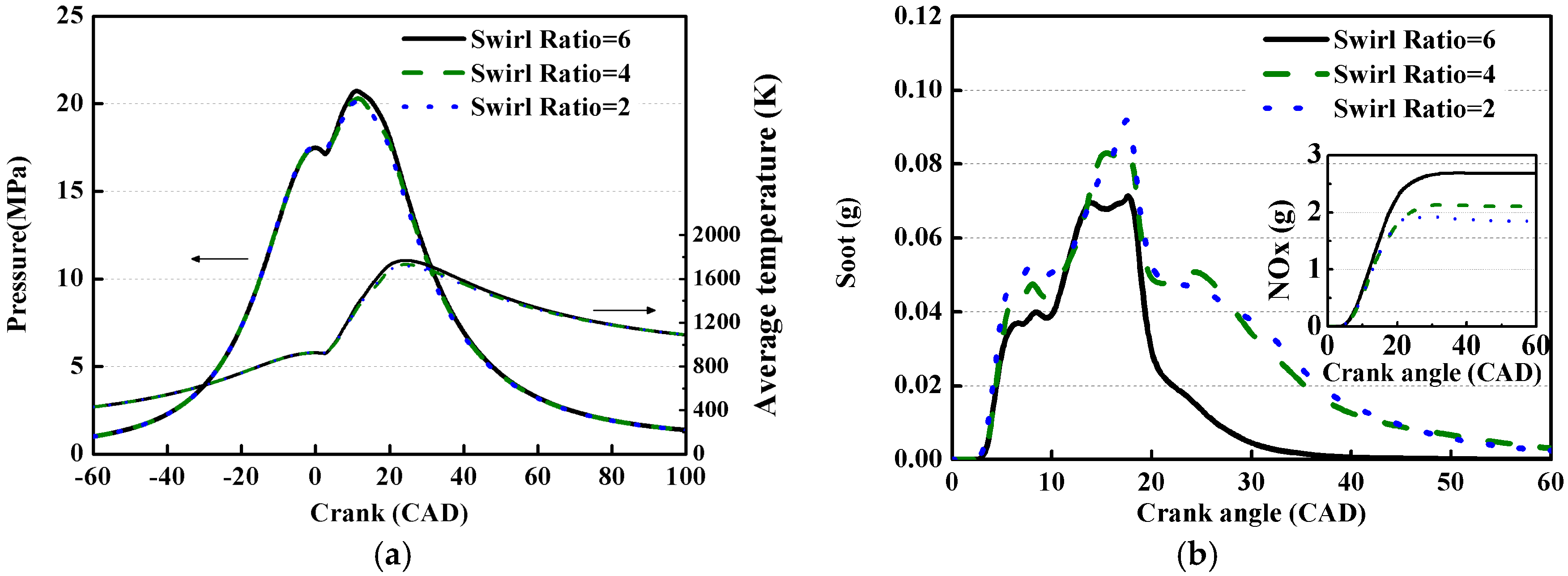
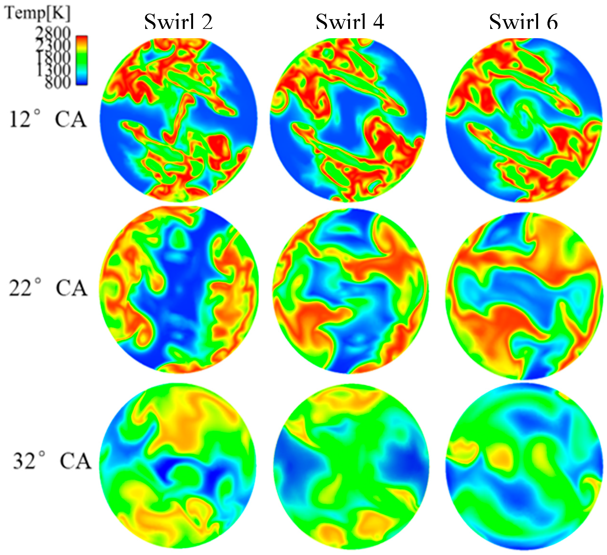
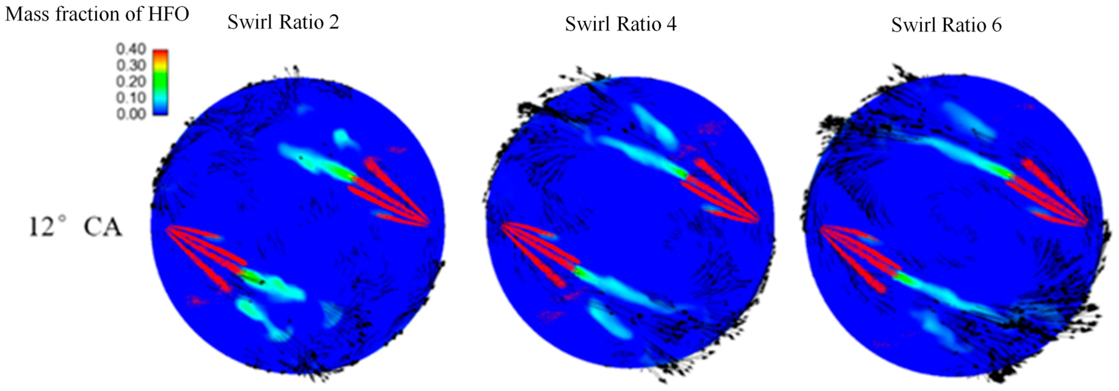
4.3.2. Effect of Swirl on Marine Engine Performance

To satisfy the emission regulations, the effects of swirl ratio on pressure, NOx, soot, and mean temperature are studied. Figure 13 shows the effects of the swirl ratio on combustion and emissions of the marine engine. It can be seen from that as the swirl ratio increases from 4 to 6, the maximum pressure increases by 4.0 bar, the maximum temperature increases by 35 K, and the NOx emissions increase by 25%. As the swirl ratio decreases from 4 to 2, the maximum in-cylinder pressure decreases by 1.5 bar, the maximum temperature decreases by 15 K, and the NOx emissions decrease by 12%. In other words, the greater the swirl ratio, the better the mixing will be. The maximum pressure and average temperature are higher, and the NOx emissions are also higher. Thus, a high swirl ratio can significantly reduce the soot production and promote combustion.
The mass fraction of HFO at the horizontal cross section between the top dead center and the injector nozzle is analyzed, and the results are shown in Figure 14. In the figure, the red color indicates liquid droplets, and the contour plot shows the mass fraction of HFO. The size and direction of the arrows in the figure indicate the size and direction of the swirl. It can be seen that two symmetrical four-hole injectors are used in the marine engine model. The eddy induced by the swirl flow will promote evaporation of the spray. It can be seen that the eddy is tangential to the injection angle. When the swirl ratio increases, the spray droplets are more dispersed, and spray vapor evaporation is enhanced.
Figure 15 shows the temperature distribution in the cylinder with different swirl ratios. It can be seen from the figure that at 12° CA ATDC (10° CA after injection of the fuel), when the cylinder combustion becomes intense and the temperature is high, the distribution of the high-temperature region is symmetrical because of symmetrical fuel injection. As the crank angle increases, the maximum temperature gradually decreases, and the distribution of temperature becomes relatively homogeneous. With the increase in swirl ratio, which can promote the evaporation of HFO according to above studies, complete combustion can occur, and hence the mean temperature is high. This can be explained from the results shown in Figure 16.
This figure shows the temperature maps for swirl ratios of 2, 4, and 6 at 10° CA ASOI. It can be seen that when the swirl ratios are 2 and 4, there are zones of low temperature combustion in the cylinder. As the swirl ratio increases to 6, the low temperature reaction zone gradually disappears, and the flame is concentrated in the zone of diffusion flame, which also indicates high temperature combustion. Consequently, the high temperature induces high NOx production.

5. Conclusions

The objective of this work was to conduct parameter sensitivity studies based on numerical simulations on spray, combustion, and emissions of HFO and diesel. The results are compared with experimental data. The thermophysical properties of the fuels are adopted from those of HFO and diesel. The injections of HFO and diesel are performed in an RFCVCC. The combustion of HFO is performed in an FIA. To study the effect of activation energy of HFO and diesel on engine performance, a marine engine is employed.
The effects of ambient pressure, swirl flow, ambient temperature, and fuel temperature on the HFO and diesel spray process are comprehensively studied. Because of the poor properties of HFO, such as viscosity and critical temperature, the liquid penetration of HFO is larger than that of diesel. The liquid spray penetration length of HFO is nearly the same as the vapor penetration length. The vapor penetration lengths obtained from simulations agree well with test data. An increase in the ambient pressure promotes fuel evaporation due to strong ambient air-liquid interactions; hence, the difference in the vapor penetration lengths of HFO and diesel reduces. The results show that a strong swirl flow suppresses spray penetration and enhances gas-liquid interaction, which in turn promotes fuel evaporation. The swirl flow has significant influence on diesel spray than on HFO. On the influences of the ambient temperature and fuel temperature, it can be concluded that the increases in either of these parameters can promote fuel evaporation of both HFO and diesel. However, these parameters have only a slight influence on spray penetration. Further, they have the negative effect on SMD. The main reason is that the ambient temperature influences the size of the peripheral droplets of the spray, which have smaller droplet radius. Furthermore, increasing the fuel temperature reduces the overall number of droplets, including both large and small droplets.
The simulations in a marine engine show that the mean in-cylinder pressures are not sensitive to activation energy at low engine speeds because the low engine speed allows enough time for fuel autoignition and high-compression pressure at TDC reduces the difference in the ignition delay time for different activation energies. However, the difference in the cylinder pressures at activation energies of 77.4 and 104.22 kJ/mol increases as the engine speed increases. Compared with HFO, the combustion performance of diesel is more sensitive to activation energy. Because of the delay in heat release, in most cases with the activation energy of 129 kJ/mol, burning does not occur, except in the case HFO at a speed of 169 rpm. A high swirl ratio can significantly promote evaporation and improve the combustion process. Consequently, the soot emission is reduced, but the NOx emission increases. In addition, by increasing the swirl ratio, the some low temperature combustion zone disappears and combustion moves toward the high-temperature flame. The main reason is that the high swirl flow promotes the liquid fuel evaporation and homogeneity mixture formation.
The present study covers the sensitively analysis of HFO spray and combustion under low-speed, two-stroke marine engine−like conditions. The results of this study can provide a new insight into the spray combustion characteristics of HFO used in marine engines.

Acknowledgments

The work is supported by National Natural Science Foundation of China (Grant No. 51606133, 91641203) and National Key Technology Support Program (2015BAG16B00).

Author Contributions

Haiqiao Wei and Lei Zhou planned the research work, and checked the calculated results. Lei Zhou and Aifang Shao wrote the manuscript. Aifang Shao and Xi Chen simulated the all the cases.

Conflicts of Interest

The authors declare no conflict of interest.

References

  1. Geng, P.; Tan, Q.; Zhang, C.; Wei, L.; He, X.Z. Experimental investigation on NOx and green house gas emissions froma marine auxiliary diesel engine using ultralow sulfur light fuel. Sci. Total Environ. 2016, 572, 467–475. [Google Scholar] [CrossRef] [PubMed]
  2. Sausen, R. Transport impacts on atmosphere and climate. Atmos. Environ. 2010, 44, 4646–4647. [Google Scholar] [CrossRef]
  3. Alegret, G.; Llamas, X.; Vejlgaard-Laursen, M.; Eriksson, L. Modeling of a large marine two-stroke diesel engine with cylinder bypass valve and EGR system. IFAC-Pap. OnLine 2015, 48, 273–278. [Google Scholar] [CrossRef]
  4. Moldanová, J.; Fridell, E.; Popovicheva, O.; Demirdjian, B.; Tishkova, V.; Faccinetto, A.; Focsa, C. Characterisation of particulate matter and gaseous emissions from a large ship diesel engine. Atmos. Environ. 2009, 43, 2632–2641. [Google Scholar] [CrossRef]
  5. Natale, F.D.; Carotenuto, C. Particulate matter in marine diesel engines exhausts: Emissions and control strategies. Transp. Res. Part D 2015, 40, 166–191. [Google Scholar] [CrossRef]
  6. International Maritime Organization (IMO). International Convention for the Prevention of Pollution from Ships (MARPOL), Regulations for the Prevention of Air Pollution from Ships (Annex VI). Available online: www.imo.org (accessed on 19 May 2005).
  7. Zhou, N.H.; Yang, J. Reducing emissions by optimising the fuel injector match with the combustion chamber geometry for a marine medium-speed diesel engine. Transp. Res. Part D 2017, 53, 1–16. [Google Scholar]
  8. Stratsianis, V.; Kontoulis, P.; Kaiktsis, L. Effects of fuel post-injection on the performance and pollutant emissions of a large marine engine. J. Energy Eng. 2016, 2, 142. [Google Scholar] [CrossRef]
  9. Sarvi, A.; Zevenhoven, R. Large-scale diesel engine emission control parameters. Energy 2010, 35, 1139–1145. [Google Scholar] [CrossRef]
  10. Herrmann, K.; Schulz, R.; Weisser, G.; Boulouchos, K.; Schneider, B. Reference Data Generation of Spray Characteristics in Relation to Large 2-Stroke Marine Diesel Engines Using a Novel Spray Combustion Chamber Concept. In Proceedings of the 23rd Annual Conference on Liquid Atomization and Spray Systems, Zürich, Switzerland, 15–18 May 2011. [Google Scholar]
  11. Kai, H.; Rotz, B.V.; Schulz, R.; Weisser, G.; Schneider, B. A “Spray Combustion Chamber“ Facility for Investigation in Relation to Large 2-Stroke Marine Diesel Engine Combustion System Optimization. In Proceedings of the International Symposium on Marine Engineering, Kobe, Japan, 17–21 October 2011. [Google Scholar]
  12. Herrmann, K.; Schulz, R.; Weisser, G. Development of a reference experiment for large diesel engine combustion system optimization. In Proceedings of the CIMAC Congress, Vienna, Austria, 21–24 May 2007. [Google Scholar]
  13. Tagasaki, K.; Tajima, H.; Nakashima, M.; Ishida, H. Combustion characteristics of trouble-making bunker fuel oil. MTZ Worldw. 2002, 63, 18–20. [Google Scholar] [CrossRef]
  14. Strom, A.; Tajima, H.; Murakami, S.; Asaura, S. Combustibility evaluation of heavy fuel oil by modified fuel ignitability analyzer. J. Mar. Eng. Soc. Jpn. 2005, 41, 56–63. [Google Scholar]
  15. Hult, J.; Matlok, S.; Mayer, S. Optical Diagnostics of Fuel Injection and Ignition in a Marine Two-Stroke Diesel Engine. Comput. Struct. 2014, 7, 1195–1206. [Google Scholar] [CrossRef]
  16. Anderson, M.; Salo, K.; Hallquist, M.; Fridell, E. Characterization of particles from a marine engine operating at low loads. Atmos. Environ. 2015, 101, 65–71. [Google Scholar] [CrossRef]
  17. Kalligeros, S.; Zannikos, F.; Stournas, S.; Lois, E.; Anastopoulos, G. An investigation of using biodiesel/marine diesel blends on the performance of a stationary diesel engine. Biomass Bioenergy 2003, 24, 141–149. [Google Scholar] [CrossRef]
  18. Gokalp, B.; Soyhana, H. Performance and emissions of a diesel tractor engine fueled with marine diesel and soybean methyl ester. Biomass Bioenergy 2011, 35, 3575–3583. [Google Scholar] [CrossRef]
  19. Struckmeier, D.; Tsuru, D.; Kawauchi, S.; Tajima, H. Multi-component modeling of evaporation, ignition and combustion processes of heavy residual fuel oil. SAE Int. 2009. [Google Scholar] [CrossRef]
  20. Kyriakide, N.; Chryssakis, C.; Kaiktsis, L. Influence of Heavy Fuel Properties on Spray Atomization for Marine Diesel Engine Applications. SAE Int. 2009. [Google Scholar] [CrossRef]
  21. Stamoudis, N.; Chryssakis, C.; Kaiktsis, L. A two-component heavy fuel oil evaporation model for CFD studies in marine Diesel engines. Fuel 2014, 115, 145–153. [Google Scholar] [CrossRef]
  22. Chryssakis, C.; Kaiktsis, L.; Frangopoulos, A. Computational investigation of in-cylinder NOX emissions reduction in a large marine diesel engine using water addition strategies. SAE Int. 2010. [Google Scholar] [CrossRef]
  23. Reitz, R.D. Modeling atomization processes in high-pressure vaporizing sprays. At. Spray Technol. 1987, 3, 309–337. [Google Scholar]
  24. Ricart, L.M.; Reltz, R.D.; Dec, J.E. Comparisons of diesel spray liquid penetration and vapor fuel distributions with in-cylinder optical measurements. J. Eng. Gas Turbines Power 2000, 122, 588–595. [Google Scholar] [CrossRef]
  25. Kong, S.; Han, Z.; Reitz, R.D. The development and application of a diesel ignition and combustion model for multidimensional engine simulation. SAE Int. 1995. [Google Scholar] [CrossRef]
  26. Wauquier, J.P.; Smith, D.H. Crude Oil, Petroleum Products, Process Flowsheets; Editions Technips: Rueil-Malmaison, France, 1995. [Google Scholar]
  27. Post, S.L.; Abraham, J. Modeling the outcome of drop–drop collisions in Diesel sprays. Int. J. Multiph. Flow 2002, 28, 997–1019. [Google Scholar] [CrossRef]
  28. Schmidt, D.P.; Rutland, C.J. A New Droplet Collision Algorithm. J. Comput. Phys. 2000, 164, 62–80. [Google Scholar] [CrossRef]
  29. Hiroyasu, H.; Kadota, T. Models for combustion and formation of nitric oxide and soot in direct injection diesel engines. Math. Models 1976, 6, 327–335. [Google Scholar]
  30. Chryssakis, C.; Pantazis, K.; Kaiktsis, L. Combustion modeling with heavy fuel oil for large marine diesel engine applications. In Proceedings of the the International Council on Combustion Engines CIMAC Congress, Bergen, Norway, 14–17 June 2010. [Google Scholar]
Figure 1. Computational grids for RFCVCC, FIA, and 340 marine engine simulations.(a) RFCVCC for non-reacting simulations; (b) FIA for combustion simulations; (c) 340 marine engine simulations.
Energies 10 01223 g001
Figure 2. Fuel properties of HFO and diesel. (a) Surface tension; (b) Vapor pressure; (c) Viscosity; (d) Heat of vaporization.
Energies 10 01223 g002
Figure 3. Comparison of liquid and vapor spray penetrations obtained by simulation and experiment for HFO and diesel under different ambient pressures. (a) Liquid phase penetration at 3 MPa of ambient pressure; (b) Vapor phase penetration at 3 MPa of ambient pressure; (c) Liquid phase penetration at 6 MPa of ambient pressure; (d) Vapor phase penetration at 6 MPa of ambient pressure; (e) Liquid phase penetration at 9 MPa of ambient pressure; (f) Vapor phase penetration at 9 MPa of ambient pressure.
Energies 10 01223 g003aEnergies 10 01223 g003b
Figure 4. Comparison of spray configurations under different spray orientations at 9 MPa of ambient pressure at 3 ms after start of injection. (a) Liquid penetrations; (b) Vapor penetrations.
Energies 10 01223 g004
Figure 5. Injection angles used in HFO and diesel simulations.
Energies 10 01223 g005
Figure 6. The evolutions of evaporated mass of HFO and Diesel fuels. (a) HFO; (b) Diesel.
Energies 10 01223 g006
Figure 7. Comparison of diesel and HFO spray characteristics under different ambient temperatures. (a) Liquid penetration; (b) Evaporated mass; (c) SMD; (d) Parcel radius.
Energies 10 01223 g007
Figure 8. Comparison of diesel and HFO spray characteristics under different fuel temperatures. (a) Liquid penetration; (b) Evaporated mass; (c) SMD; (d) Parcel radius.
Energies 10 01223 g008
Figure 9. Heat release rate of HFO at different activation energies.
Energies 10 01223 g009
Figure 10. Combustion performance of marine engine fueled with HFO at different engine speeds. (a) 169 rpm; (b) 338 rpm; (c) 676 rpm.
Energies 10 01223 g010
Figure 11. NOx of marine engine fueled with HFO at different engine speeds.
Energies 10 01223 g011
Figure 12. Combustion performance of marine engine fueled with diesel-like fuel at different engine speeds. (a) 169 rpm; (b) 676 rpm.
Energies 10 01223 g012aEnergies 10 01223 g012b
Figure 13. Combustion and emission performances of HFO at different swirl ratios. (a) Pressure and average temperature; (b) Soot and NOx.
Energies 10 01223 g013
Figure 14. Distributions of gas and liquid phases of spray and flow field.
Energies 10 01223 g014
Figure 15. Distribution of cylinder temperature under different swirl ratios.
Energies 10 01223 g015
Figure 16. Map of equivalence ratio vs. temperature under different swirl ratios. (a) Swirl = 2; (b) Swirl = 4; (c) Swirl = 6.
Energies 10 01223 g016
Table 1. Specifications and configurations of RFCVCC and FIA.
Engine SpecificationsRFCVCCFIA
Diameter (mm)500190
Height (mm)15065
Ambient pressure (bar)90/60/3045
Ambient temperature (K)900823
Injection pressure (bar)1000550
Injection duration (ms)2520
Injection mass (g)4.40.087
Nozzle diameter (mm)0.8750.16
Injection temperature (K)400375
Swirl velocity (m/s)15–250
Gas compositionN2 (non-reacting)N2, O2
Table 2. Specifications and configurations of the marine engine.
Engine SpecificationsConfigurations
Cylinder bore (mm)340
Stroke (mm)1600
Compression ratio20.5
Speed (rpm)169
Simulated initial time78° BTDC
Simulated end time108° ATDC
Initial swirl ratio4
Initial cylinder temperature (K)372
Initial cylinder pressure (bar)6
Start of injection timing2° CA ATDC
Injection duration (CAD)15.36

