Article

A Sliding Surface-Regulated Current-Mode Pulse-Width Modulation Controller for a Digital Signal Processor-Based Single Ended Primary Inductor Converter-Type Power Factor Correction Rectifier

Department of Electrical Engineering, National Dong Hwa University, Hualien 97401, Taiwan
*
Author to whom correspondence should be addressed.
Energies 2017, 10(8), 1175; https://doi.org/10.3390/en10081175
Submission received: 10 July 2017 / Revised: 2 August 2017 / Accepted: 7 August 2017 / Published: 9 August 2017
(This article belongs to the Section F: Electrical Engineering)

Abstract

:
To efficiently supply wide-range DC voltage from a pulse-width modulation (PWM) rectifier, this paper presents a single-phase, full-wave, diode-bridge, single-ended primary-inductor converter-type (SEPIC-type) power-factor-correction (PFC) rectifier in continuous conduction mode with a sliding surface-regulated current-mode PWM controller. According to the switched-mode operation of the rectifier, a fourth-order switch model of the SEPIC is derived. From the fourth-order model, a simplified state-averaged model which approximately describes the dynamic behaviors of both the output voltage and inductor current is proposed. Then, from the simplified state-averaged model, the sliding surface-regulated current-mode PWM controller for the SEPIC-type PFC rectifier is proposed. The sliding surface-regulated current-mode PWM controller comprises a sliding-mode voltage controller in outer loop for robust control of the output DC-voltage and a sliding-mode current controller in inner loop for phase-synchronized control of the inductor current. For experimental studies, implementation of the proposed control algorithm in a DSP controller and a laboratory prototype of the SEPIC-type rectifier with the DSP-based PWM controller were carried out. Experimental results from the DSP controller-applied SEPIC-type rectifier are illustrated to confirm the validity of the proposed controller for practical applications.

1. Introduction

During the past twenty years, numerous publications on the development of power-factor-correction (PFC) pulse-width modulation (PWM) AC-to-DC converters have been published [1,2,3,4,5,6,7,8,9,10,11,12,13,14,15]. In these switched-mode PFC converters, an idea about how to achieve zero reactive power with unity power factor (UPF) in AC source line is often discussed. Two classes roughly grouped from the presented PFC schemes are as follows: (1) integration and modification in hardware circuits of power converters [1,2,3,4,5,6,7,8,9]; and (2) application of the developed control techniques to AC-to-DC or DC-to-DC converters [10,11,12,13,14,15,16,17,18,19,20,21,22,23,24,25]. The studies in [1,2,3,4,5,6,7,8,9] can be summarized as follows: in [1,2], an additional LC-diode clamper or snubber was integrated into the specified or multilevel converters so that the PFC was completed through the additional clamper or snubber. In [3,4,5,6], an integration of the selected two types of converters or an auxiliary circuit were employed to form a PFC rectifier or converter. Furthermore, a multiple-level conversion stage [7], a modified converter topology [8], and a three-phase SEPIC converter under discontinuous conduction mode operation [9] were proposed. From their experimental results, one can find that these presented PFC converters can improve the power-factor (PF) by the designed circuits of the switched-mode converters; however, the topologies of the designed converter circuits are obviously complicated more than those of the basic step-up/-down PWM converters.
On the other hand, PWM technique-based voltage control methods developed for switched-mode unity-power-factor rectifiers or converters were presented in [10,11,12,13,14,15,16,17,18]. In [10,11], fuzzy logic controllers were used in power converters. Although these controllers can improve the PF in AC source line, experienced fuzzy rules [10] or additional variable DC voltage source [11] were usually required. Adaptive controllers [12,13], and robust controllers [13,14] were developed for building the PFC converters. From the illustrated experimental results for validation, we can find that the PF in AC source line is regulated nearly to unity. However, due to the complication of the developed controllers, implementation of the control algorithms in a microcontroller/microprocessor is difficult.
There have many publications about sliding-mode control technologies [16,17,18]. This is because the sliding-mode control method has advantages of high-performance transient response, strong relative stability, and robustness to system uncertainty/disturbance. Due to the abovementioned advantages, studies in sliding-mode control methods for electric motor drives [19,20], robotics [21], and switched-mode converters [22,23,24,25,26,27,28,29,30,31] have been presented in many publications. From [22,23,24,25,26,27,28,29,30,31], one can find that the converters with the SMC methods often can effectively improve the PF of AC-side line and possess robustness of the output voltage to load variations. However, these SMC methods developed have drawbacks as follows. In [22,23,24], the SMC schemes were developed from the state averaged model or small-signal model, a linearized model, of the converters. In [25,26,27,28], the current references to be tracked always contain the parameter values of the load and input voltage, and the complicated double-integral operator in [28] was used to generate the current reference. Hence, to avoid the drawbacks mentioned above, [29,30,31] presented a cascaded control approach of the sliding-mode current-loop controller connected in series with a proportional-integral (PI) [29,30] or an integral [31] voltage-loop controller. In this cascaded control approach, the current reference for the sliding-mode current controller was generated from the output of the voltage-loop controller. This approach often leads to a difficulty in improving the transient performance of voltage time responses.
Therefore, to apply advantages of the sliding-mode control techniques to a unity-power-factor PWM rectifier. Therefore, this paper develops a SEPIC-type PFC rectifier with the sliding surface-regulated current-mode PWM controller, in which the controller is developed from a simplified state-averged model of the SEPIC-type PWM converter. For the sake of wide-range DC voltage supply, the SEPIC-type AC-to-DC converter is adopted. Moreover, for the controller development, the simplified state-averaged model derived from the full-order switch-mode of the SEPIC converter is proposed. On the basis of the simplified state-averaged mode, the sliding surface-regulated current-mode PWM controller is developed. Using the developed controller to the PWM rectifier, the power factor, high-performance and robustness in output DC volatge, and conversion efficiency improvement can be obtained, and the standards of IEC 61000-3-2 and IEEE are also satisfied. Implementation of the developed control algorithms in a digital-signal-processor (DSP) and a laboratory prototype of single-phase/full-wave diode-bridge, SEPIC-type PWM rectifier with the DSP controller were carried out, and simulation work based on the Simulink models was performed. To confirm the feasibility of the developed PFC rectifier, simulation and experimental results from the built Simulink models and the laboratory rectifier system, respectively, were illustrated. From the illustrated results one can conclude that the developed PFC rectifier is valid not only for improving the power factor, increasing the conversion efficiency, and decreasing the THD, but also to meet the standards of IEC 61000-3-2.

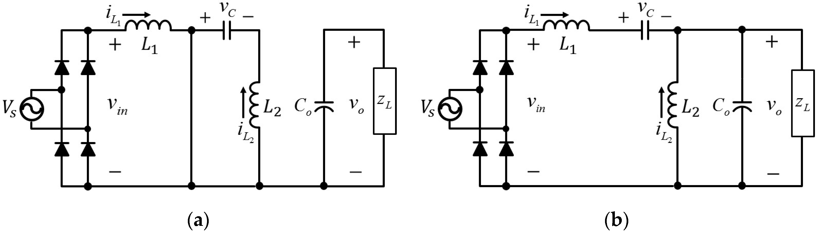
2. Modeling of Switch-Mode SEPIC-Type Rectifier

A schematic layout of the SEPIC-type rectifier is shown in Figure 1, where z L denotes an equivalent resistive-inductive load and the SEPIC converter is used for wide-range voltage transformation from v i n to v o . Under this layout given in Figure 1, one of the methods for increasing the conversion efficiency from AC source to the output DC-voltage is to improve the PF of the AC source [32,33,34]. Therefore, to achieve high-performance output DC-voltage response with PFC, the sliding surface-regulated current-mode PWM controller for the SEPIC-type PFC rectifier will be developed in this paper.

2.1. Full-Order State-Averaged Model

Due to the turning on and off of the power switch of Q in Figure 1, operation modes for the SEPIC converter [9,34], in continuous conduction mode (CCM) can be classified in two stages, as shown in Figure 2a,b, named as Stage 1 (switch is turned on) and Stage 2 (switch is turned off), respectively. According to the two stages, the dynamic equations of the converter can be developed as follows:
Stage 1: the power switch of Q of the rectifier is turned on for an interval, as shown in Figure 2a. During the on-state of the switch Q, the dynamic equations of the SEPIC converter can be written as below:
C o d v o d t = v o z L L 1 d i L 1 d t = v i n L 2 d i L 2 d t = v c C d v c d t = i L 2
Stage 2: the power switch of Q of the rectifier is turned off for an interval, as shown in Figure 2b. During the off-state of the switch Q, the dynamic equations of the SEPIC converter can be written as below:
C o d v o d t = ( i L 1 + i L 2 ) v o z L L 1 d i L 1 d t = v i n v c v o L 2 d i L 2 d t = v o C d v c d t = i L 1
Therefore, from (1) and (2), the full-order state-averaged model [34] can be described as follows:
v ˙ o = 1 z L C o v o + 1 C o ( i L 1 + i L 2 ) ( 1 d ) i ˙ L 1 = 1 L 1 ( v o + v c ) ( 1 d ) + 1 L 1 v i n i ˙ L 2 = 1 L 2 v o ( 1 d ) + 1 L 2 v c d v ˙ c = 1 C i L 1 ( 1 d ) 1 C i L 2 d
where d denotes the duty cycle employed in PWM technique. Because this study is mainly to control the output DC voltage of v o and to improve the PF-contained inductor current of i L 1 of the PWM rectifier, a simplified state-averaged model will be futher derived from (3) in the next subsection to make the model-based controller development simpler.

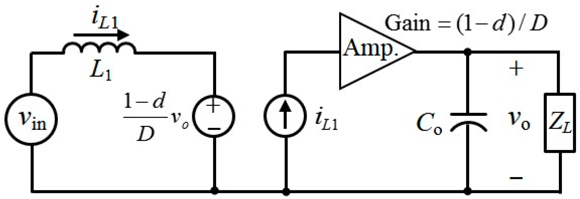
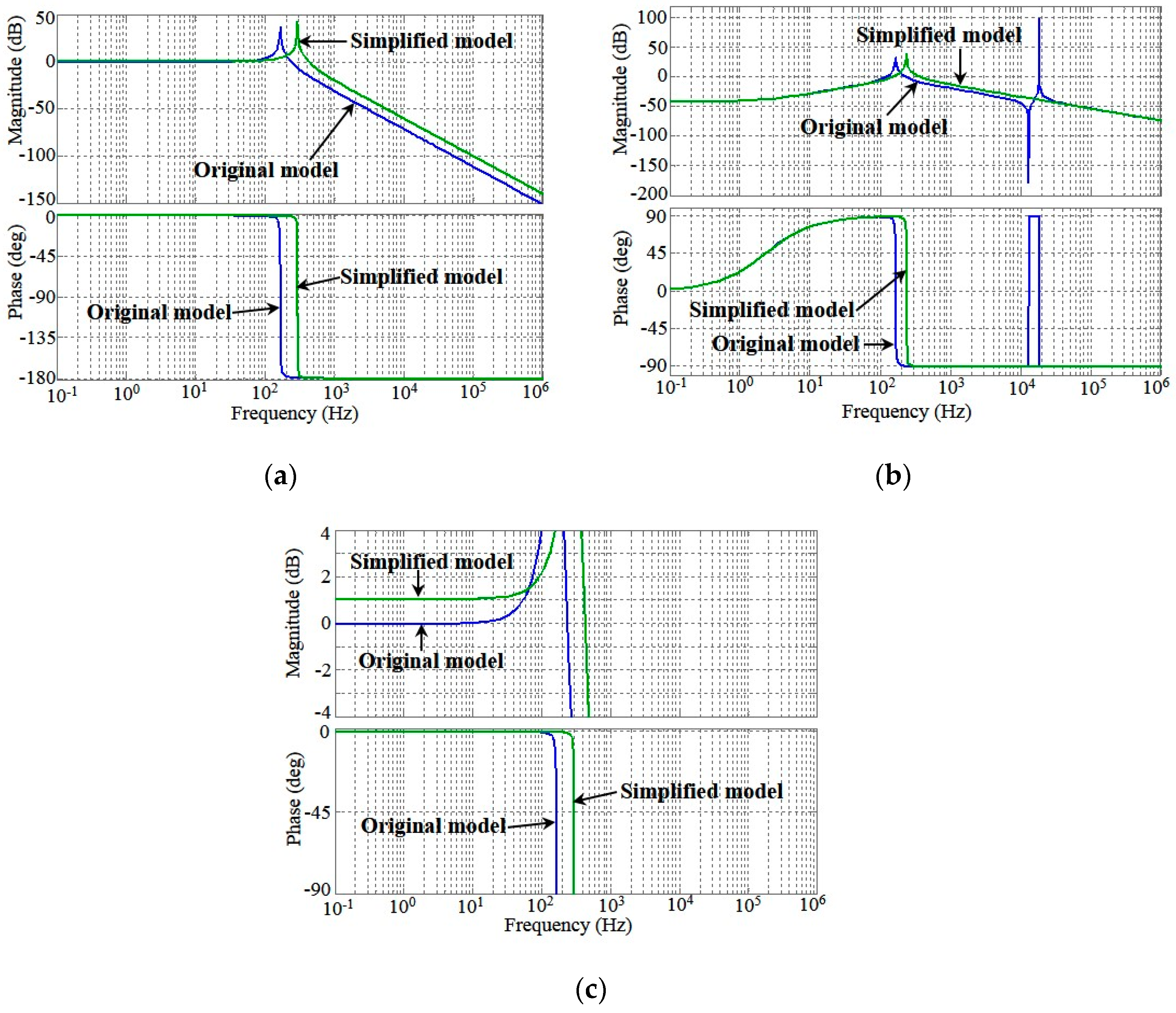
2.2. Simplified State-Averaged Model

For realizing a high-performance PWM rectifier, full-order model-based controllers for the rectifier were often developed [15,24,27]. However, there will become complex if the full-order model of (3) is taken for the controller development for the high-performance SEPIC-type rectifier. To reduce the complexity of the controller design, the simplified model which equivalently describes the output DC-voltage and inductor current of the SEPIC-type rectifier is derived in the following. Considering the SEPIC module of Figure 1 to be a DC-to-DC converter, the last two equations of (3) in steady state can be expressed by:
0 = 1 L 2 v o ( 1 D ) + 1 L 2 v c D 0 = 1 C i L 1 ( 1 D ) 1 C i L 2 D
where D denotes the steady-state duty of d in switching-mode operation. From (4) it gives:
v c = 1 D D v o   and   i L 2 = 1 D D i L 1
Substituting (5) into (3) gives the simplified state-averaged model in the following:
v ˙ o = 1 z L C o v o + ( 1 d ) C o 1 D i L 1 i ˙ L 1 = v o D L 1 ( 1 d ) + 1 L 1 v i n
According to (6), the simplified state-averaged model can be depicted in Figure 3. From Figure 3 and the control theory point of view, one can realize that the output voltage of v o can be regulated through the state variable of i L 1 with the gain of ( 1 d ) / D , and the inductor current of i L 1 can directly be controlled by the variable of d, i.e., the duty ratio for driving the PWM rectifier. Under the realization mentioned above, the state of i L 1 is purposely taken as the equivalent control effort for the output voltage v o and the duty ratio of d is taken as the current controller for the inductor current i L 1 .
To confirm the simplified model of (6) being ready for the model-based controller development, Bode diagrams of the original model and the simplified state-averaged model of the PWM rectifier are shown in Figure 4. Figure 4a−c indicate the frequency response of the input-to-DC-voltage, input-to-inductor-current, and a zoom-in window of Figure 4a, respectively. From view of Figure 4, the frequency responses of the DC-voltage and inductor current of the simplified model approximates those of the original state-averaged model.
Moreover, the DC-voltage time responses due to step changes in the duty of d from 0.4 to 0.6 and then back to 0.4 is shown in Figure 5. Figure 5 it shows that the time response of the simplified model of (6) also approximates that of the original state-averaged model of the PWM rectifier, although a steady-state error exists due to a little difference over low-frequency range, as shown in Figure 4c. From Figure 4 and Figure 5 one can confirm that the controller development based on the simplified model of (6) is achievable.

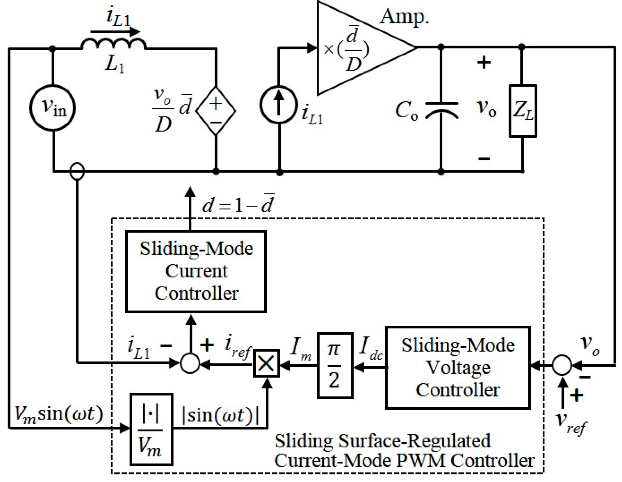
3. Sliding Surface-Regulated Current-Mode PWM Controller

The objectives of the controller to be developed contain that (1) the DC-voltage response of the SEPIC-type rectifier is robust to load variation; and (2) conversion efficiency of the rectifier with a resistive-inductive load is improved by regulating the PF of AC source to unity. Therefore, as shown in Figure 6, the sliding surface-regulated current-mode PWM controller is proposed for achievement of an efficient SEPIC-type PFC rectifier.

3.1. Sliding-Mode Voltage Controller with Integral Sliding Surface

Considering the load uncertainty of the PWM rectifier, Equation (6) can be expressed as:
v ˙ o = ( 1 z L C o + Δ L ) v o + d ¯ C o 1 D i L 1 i ˙ L 1 = v o D L 1 d ¯ + 1 L 1 v i n
where Δ L denotes an uncertainty due to load variation. Define the state variables in the following:
e v 1 = ( v o v r e f ) d t e v 2 = v o v r e f
where v r e f denotes a constant DC-voltage reference to be tracked. Taking the time derivative of (8) yields the voltage error dynamics in the following:
e ˙ v 1 = e v 2 e ˙ v 2 = 1 z L C o v o + b 1 i L 1 + Δ L Z
where b 1 = d ¯ / C o D , Δ L Z = Δ L v o denotes the load uncertainty, and i L 1 is regarded as the control effort to be developed. Designate the sliding surface S v as:
S v = α 1 e v 1 + e v 2
where α 1 is a suitable positive constant. From (9) and (10), the sliding-mode voltage controller is given by:
I d c i L 1 = 1 b 1 [ 1 z L C o v o α 1 e v 2 β 1 sgn ( S v ) ]
where β 1 denotes the upper bound of | Δ L Z | , i.e., | Δ L Z | β 1 , and sgn ( ) is the signum function satisfying:
sgn ( S v ) = { + 1 ,   as   S v > 0 1 ,   as   S v < 0
Then, the stability of the voltage error dynamics of (9) with the controller of (11) can be demonstrated as follows. Choose the Lyapunov function candidate [16] as:
V 1 = 1 2 S v 2
Taking the time derivative of (13) yields:
V ˙ 1 = S v S ˙ v = α 1 e ˙ v 1 + e ˙ v 2 = α 1 e v 2 1 z L C o v o + b 1 i L 1 + Δ L Z
Substituting (11) into (14) and using the triangular inequality [16,17,18] gives:
S v S ˙ v = S v [ Δ L Z β 1 sgn ( S v ) ] = S v Δ L Z β 1 | S v | | S v Δ L Z | β 1 | S v |    | S v | | Δ L Z | β 1 | S v | = | S v | ( β 1 | Δ L Z | ) 0
From (13) to (15), it can give that the sliding surface of S v converges to zero as t [16,17,18,35]. When the state of S v = 0 is always kept, it can imply the result of S v = S ˙ v = 0 . Hence:
S ˙ v = α 1 e ˙ v 1 + e ˙ v 2 = α 1 e v 2 + e ˙ v 2 = 0
From Equation (16) one can find that the exponential convergence of the voltage error of e v 2 is given. Then, when e v 2 = 0 and S v = 0 are always kept, e v 1 = 0 can also be achieved. Therefore, from the above proof one can find that the voltage error dynamics of (9) with load uncertainty can asymptotically stabilized by (11). That is, the output DC-voltage of the SEPIC-type PWM rectifier can asymptotically track the voltage reference even that the load uncertainty is present.

3.2. Sliding-Mode Current Controller with PFC

From Figure 6 and the first equation of (7), one can interpret that the output voltage v o of the rectifier is introduced by charging of the capacitor C o through the averaged DC-current of i L 1 . Under this interpretation, one may conclude that the sliding-mode voltage controller of (11) equivalently gives an averaged DC variable of I d c . However, for control of the PFC rectifier, the current reference to be tracked by the current controller must be synchronized with the phase of the AC voltage source of V m sin ( ω t ) , where V m and ω denote the amplitude and frequency of the AC voltage source, respectively. Therefore, the averaged DC variable of I d c needs to be transformed to the current reference with the synchronized phase of the AC source. From [33,34] one can find that the averaged DC output of the single-phase, full-wave, diode-bridge rectifier module is equal to I d c = ( 2 / π ) I m , where I m denotes the amplitude of the rectified sinusoidal-current with the form of I m | sin ( ω t ) | . Therefore, the current reference to be tracked can be given by:
i r e f = I m | sin ( ω t ) | = π 2 I d c | sin ( ω t ) |
As a result, the phase-synchronized current reference of i r e f for the inner-loop current controller is given from the transformation of (17).
Similarly to (8), we define the state variable of the current error as follows:
e i = i L 1 i r e f
Taking the time derivative of (18) yields the current error dynamics in the following:
e ˙ i = v o D L 1 d ¯ + 1 L 1 v i n i ˙ r e f
For an easier analysis in stability, the sliding surface S c for control of (19) is designated in the following:
S c = e i
With the sliding surface of (20), the current-mode PWM controller is designated by:
d ¯ = Φ ( S c ) = 0.5 × [ 1 + S a t ( S c ) ]
where 0 Φ ( S c ) 1 and S a t ( ) and is a saturation operator shown in Figure 7. In Figure 7, the parameters of S p and S N denote the positive and negative bands of the sliding surface S c for switching. The main idea behind the controller depicted in Figure 7 is as follows. When the current error is positive, i.e., i L 1 > i r e f , the output of Φ ( S c ) will yield an off-duty larger than 0.5 to let the inductor current decrease, which can be found from (19). On the other hand, when the current error is negative, i.e., i L 1 < i r e f , the output of Φ ( S c ) will yield an off-duty smaller than 0.5 to let the inductor current increase. As a result, the current error defined in (18) can stably be controlled by the controller of Φ ( S c ) .
Stability analysis on the sliding surface of (20) is shown as follows. Select the Lyapunov function in the following:
V 2 = 1 2 S c 2
Taking the time derivative of (22) yields:
V ˙ 2 = S c S ˙ c = S c e ˙ i = S c [ v o D L 1 d ¯ + 1 L 1 v i n i ˙ r e f ]
Substituting (21) into (23) gives:
S c S ˙ c = S c [ v o D L 1 Φ ( S c ) + 1 L 1 v i n i ˙ r e f ]
According to the sliding-mode control theory [16,17,18], the stability of (19) can be guaranteed if the condition of S c S ˙ c < 0 is ensured all the time. Hence, two cases of S c > 0 and S c < 0 in the following are considered for proof of the stability.
Case 1: S c > 0 . In this case, the following equation for stability of (19) must be satisfied:
v o D L 1 Φ ( S c ) + 1 L 1 v i n i ˙ r e f < 0
Rearranging (25) gets:
v i n Φ ( S c ) D v o < L 1 i ˙ r e f
However, from Figure 3, (26) can be written as:
v i n Φ ( S c ) D v o = L 1 d i L 1 d t < L 1 d i r e f d t
That is, to guarantee the stability in this case, the changing rate of the inductor current must be less than that of the commanded inductor current.
Case 2: S c < 0 . In this case, the following equation for stability of (19) must be satisfied:
v o D L 1 Φ ( S c ) + 1 L 1 v i n i ˙ r e f > 0
Rearranging (28) gives:
v i n Φ ( S c ) D v o = L 1 d i L 1 d t > L 1 d i r e f d t
That is, in this case, the stability of (19) can be guaranteed if the changing rate of the inductor current is larger than that of the commanded inductor current. From the above two cases and Figure 3, one can conclude as follows: when S c > 0 , i.e., i L 1 i r e f > 0 , the power switch of the PWM rectifier should be turned off to decrease the current of the inductor L 1 of the SEPIC rectifier. In this situation, the rate of change of the current in the inductor L 1 must be descent more than that of the reference command, as given in (27). Contrarily, when S c < 0 , i.e., i L 1 i r e f < 0 , the power switch should be turned on to increase the current of the inductor L 1 . In this situation, the rate of change of the current in the inductor L 1 must be incremental more than that of the reference command, as given in (29).

3.3. Stability Analysis of the PFC Rectifier

From (11) and (17), the commanded current reference of i r e f can be obtained:
i r e f = π 2 [ D d ¯ v o z L D d ¯ C o α 1 e v 2 D d ¯ C o β 1 sgn ( S v ) ] | sin ( ω t ) |
Compared with the value of D / d ¯ of the first term in the right-hand side of (30), the values of the last two terms of C o α 1 D / d ¯ and C o β 1 D / d ¯ are small enough because of a small capacitance of C o . Hence, the following approximation can be given:
i r e f π 2 [ D d ¯ v o z L ] | sin ( ω t ) |
According to (31), the derivative of (31) can be expressed by:
L 1 d i r e f d t L 1 [ v o z L D d ¯ π 2 f ] cos ( ω t )   for   n π ω t < ( n + 1 ) π ,   n = 1 ,   2 ,   3 ,
where f = ω / 2 π is the frequency of the AC source in hertz. Therefore, according to (27) and (29), the stability of (19) with the controller of (21) can be further explored in the following. Using (32) and (21), when S c > 0 , (27) can be rewritten as:
V m | sin ( ω t ) | Φ D v o < L 1 [ D Φ v o z L π 2 f ] cos ( ω t )
Multiplying Φ / D to the both side of (33) and rearranging it get:
Φ D V m | sin ( ω t ) | < [ L 1 π 2 f z L cos ( ω t ) + ( Φ D ) 2 ] v o
According to the values of the parameters adopted in this study, the value of L 1 π 2 f / z L is small enough to be ignored since 1 < Φ / D 2 . Hence, (34) is simplified to:
V m | sin ( ω t ) | < Φ D v o
Hence, with a suitable Φ ( S c ) , the inequality of (35) can be satisfied. In other words, when S c > 0 , the inductor current of i L 1 might be decreased by giving reverse voltage drop over the inductor to approach the value of S c = 0 .
On the other hand, when S c < 0 , (29) can be rewritten as:
V m | sin ( ω t ) | Φ D v o > L 1 [ D Φ v o z L π 2 f ] cos ( ω t )
Like (34), (35) can be rewritten as:
V ¯ m | sin ( ω t ) | > [ A L cos ( ω t ) + ( Φ D ) 2 ] v o
where V ¯ m = V m Φ / D and A L = L 1 π 2 f / z L . Hence, with a suitable Φ ( S c ) , the inequality of (37) can be satisfied. However, from (37) one can find that when ω t = 2 n π , n = 0 ,   1 ,   2 , , the left-hand side of (37) becomes zero. At this moment, the condition given by (37) is failed because the value of Φ almost approaches zero to make the right-hand side of (37) become a positive of A L x 1 . Fortunately, in this case, the voltage drop over the inductor is very close to zero so that the inductor keeps a small value of current until V ¯ m | sin ( ω t ) | becomes enough large one. This consequence will be demonstrated in the experimental work in Section 4.
Moreover, when the state variables of v o and i L 1 are stabilized by the developed controller, the stability of the uncontrolled state variables of i L 2 and v c in the original state-averaged system of (3) can be explored as follows. Integrating (6) and the last two equations of (3) gives:
[ i ˙ L 2 v ˙ c ] = [ 0 d L 2 d C 0 ] [ i L 2 v c ] + [ d ¯ L 2 0 0 d ¯ C ] [ v o i L 1 ] [ v ˙ o i ˙ L 1 ] = [ 1 z L C o d ¯ D C o d ¯ D L 1 0 ] [ v o i L 1 ] + [ 0 1 L 1 ] v i n
Because (38) presents a cascade system [35] with the bounded input of v o and i L 1 , the stability of the local system composed of i L 2 and v c can be confirmed by the eigenvalues of the first equation of (38) in the following:
Δ ( s ) = s 2 + d 2 L 2 C
where s denotes the Laplace operator. From viewpoint of control theories [36], the system of (38) is stable because there are two simple roots (since d 1 ) on imaginary axis and two bounded inputs of v o and i L 1 .

4. Simulation and Experimental Work

To confirm the feasibility of the developed control method on the SEPIC-type PWM rectifier by computer simulation and hardware experimentation, the software MATLAB/Simulink model (R2015a, MathWorks, Natick, MA, USA), shown in Figure 8a, and the laboratory prototype of a single-phase/full-wave diode-bridge SEPIC converter with a digital-signal-processor (DSP) controller and interface circuits of signal conditioners, shown in Figure 8b, were built. In the built hardware system in Figure 8, the power switch Q is of a MOSFET component, the gate driver is of a high-speed photocoupler, and the output voltage of the rectifier is connected to a resistive-inductive load. The values of the main parameters adopted in the system are given as follows. In the SEPIC-type rectifier, v a c = 110   V / 60   Hz , L 1 = 3.3   mH , L 2 = 2   mH , C = 1.8 μF, Co = 680 μF, inductive load of 0.1 mH, PWM switching frequency of f s = 100   kHz were adopted, and α 1 = 5 and β 1 = 2 were determined from those of the experimental step voltage responses which possess a good transient performance by comparisons.

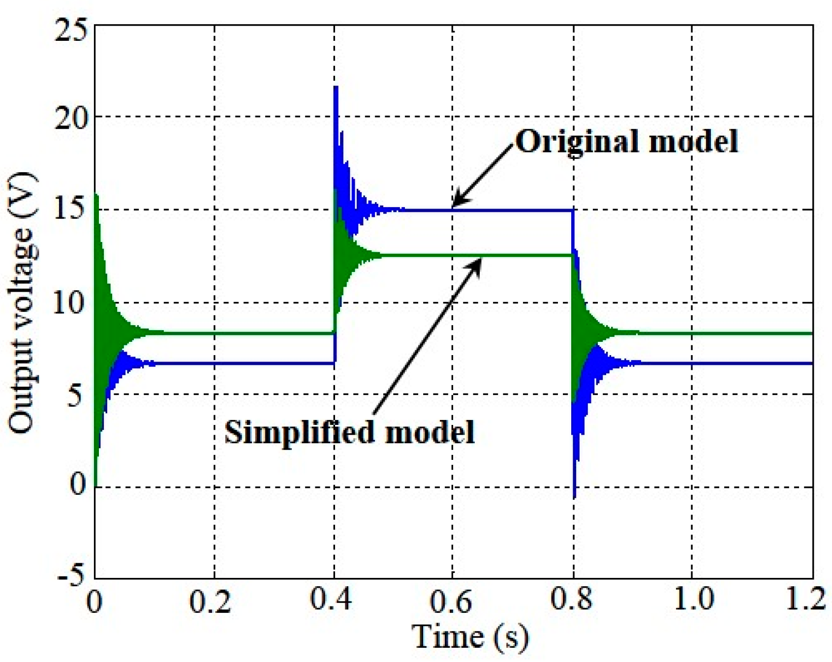
4.1. Simulation Results

For convenience of our comparisons of the performance of system responses, a single-phase PWM rectifier with the proportional-integral (PI) voltage and current controllers were also developed. Simulation results obtained from the single-phase PWM rectifier with the PI controllers and sliding surface-regulated current-mode PWM controller, respectively, are given in Figure 9a,b, where the output DC-power of 500 W is specified.
From Figure 9 one can observer that the power factor of the SEPIC-type rectifier with the sliding surface-regulated current-mode PWM controller is better than that with the PI controllers. Moreover, Figure 10 shows the simulation results about the total harmonic distortion (THD) of the SEPIC-type rectifier with the PI controllers and sliding surface-regulated current-mode PWM controller. Figure 10 shows that the magnitudes of the 3rd-, 5th-, 7th-order harmonic are effectively reduced by the proposed controller. Hence, from Figure 9 and Figure 10 it can be confirmed that using the sliding surface-regulated current-mode PWM controller to the SEPIC-type rectifier can substantially improve the power factor and THD of the PWM rectifier.

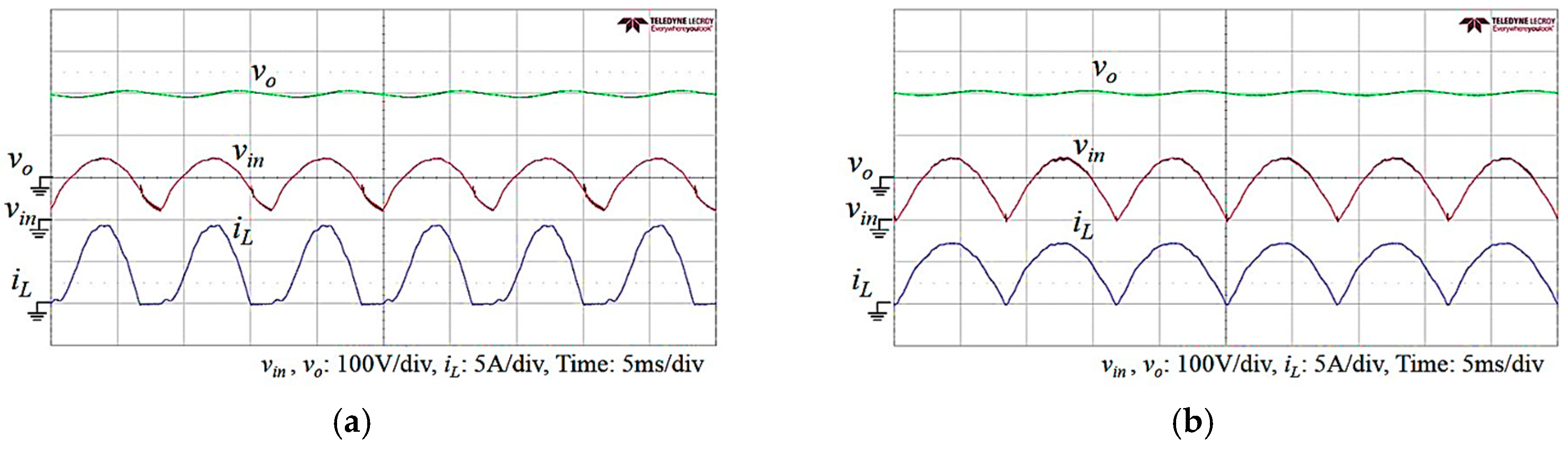
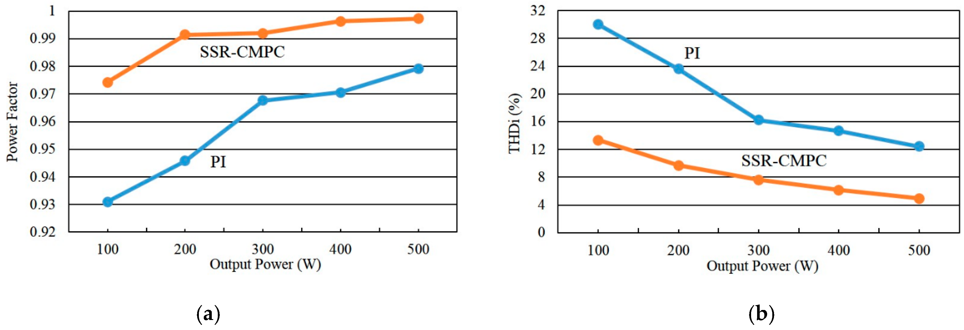
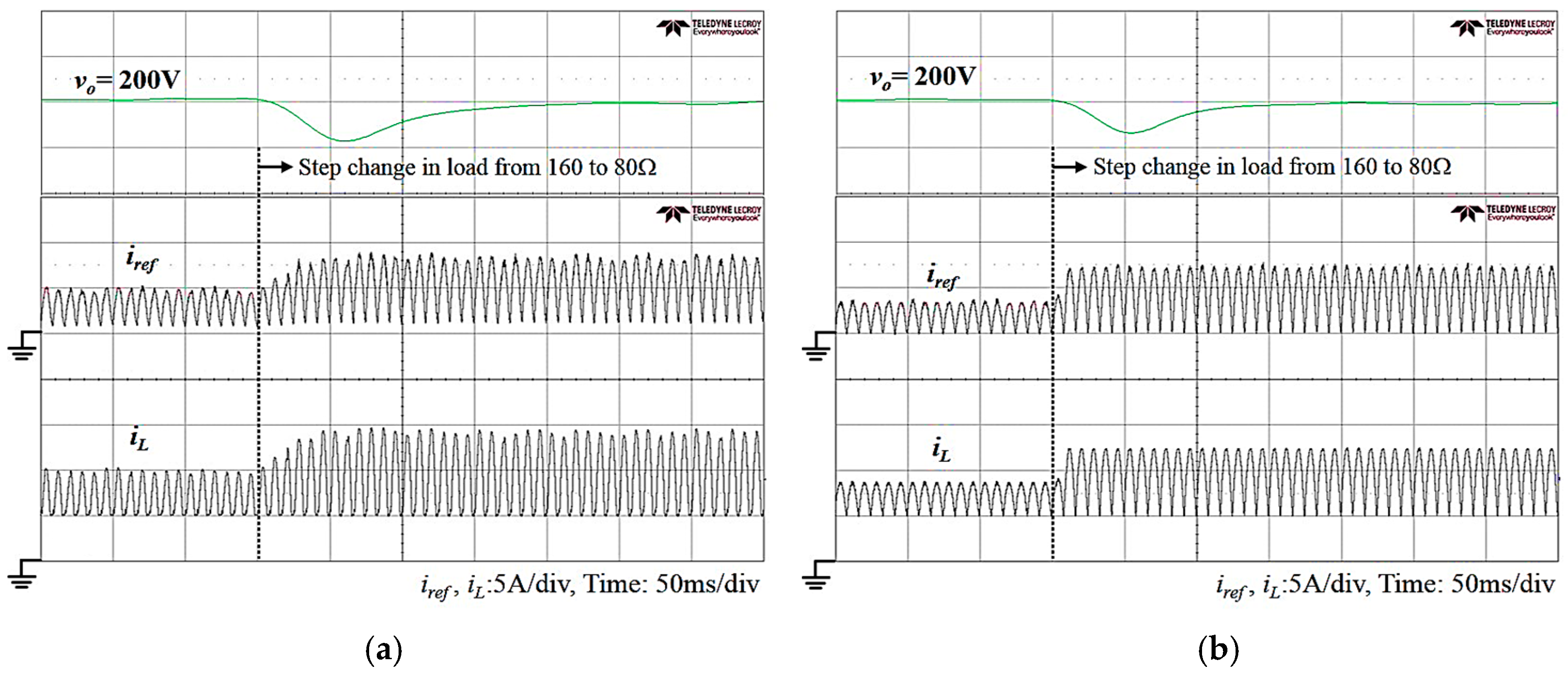
4.2. Experimental Results

For comparative investigation, experimental results of time responses of the DC-voltage output, rectified source voltage, and inductor current, respectively, of the SEPIC-type rectifier with the PI controllers and the sliding surface-regulated current-mode PWM controller are illustrated Figure 11. Also, experimental records about the PF and THD information are illustrated in Figure 12 and Figure 13. From Figure 11, Figure 12 and Figure 13 of view, one can confirm again that the PF and THD of the SEPIC-type rectifier with the sliding surface-regulated current-mode PWM controller are effectively improved in practice.
Experimental results shown in Figure 14a,b illustrate the time responses of the output DC-voltage and voltage error obtained from the SEPIC-type rectifier with the PI controller and sliding surface-regulated current-mode PWM controller, respectivey. The values of the PI controller parameters adopted in Figure 14a were determined by manual tuning to make the transient response close to Figure 14b. From Figure 14 it shows that the sliding surface-regulated current-mode PWM controller can effectively improve the transient performance of the controlled SEPIC-type rectifier. In addition, experimental time responses of the DC voltage and phase-synchronized inductor current of the controlled SEPIC-type rectifier due to step change in load from 160 Ω (250 W) to 80 Ω (500 W) are shown in Figure 15. From Figure 15, one can find that the SEPIC-type rectifier controlled by the sliding surface-regulated current-mode PWM controller has a better performance in DC voltage response than that by the PI controller, and has the robustness in DC-voltage response to load variation and high-performance current tracking with phase synchronization.

4.3. Stability Analysis by Numerical Computation

In the experiments, the amplitude of v i n about 156 V (110 Vrms, 60 Hz) and an output DC-voltage of 200 V with the load of z L = 80   Ω were employed. The computation results associated with (35) and (37) can be given as follows:
L 1 π 2 f z L cos ( ω t ) = 0.0033 × ( 3.14 ) 2 × 60 80 × cos ( ω t ) = 0.0195 × cos ( ω t )
Φ D 156 | sin ( 377   t ) | > [ 0.0195 cos ( 377   t ) + ( Φ D ) 2 ] v o
From the above results one can give that (1) the value of L 1 π 2 f / z L is practically small enough to be ignored in the mathematic analysis; and (2) while i L 1 i r e f < 0 , the condition of (37) might be unsatisfied because v i n is close to zero. However, when i L 1 i r e f < 0 , the value of Φ / D might be very close to zero. Therefore, during the time interval of v i n close to zero, the stability of (19) of the current error dynamics is not destroyed as well because a very small value of Φ / D is given and the right-hand side of (41) is always postive, which can be shown in Figure 16b and Figure 17.

5. Conclusions

In this paper, a sliding surface-regulated current-mode PWM controller for a single-phase/full-wave diode-bridge SEPIC-type PFC rectifier was developed. First, the fourth-order state-averaged model of the SEPIC-type rectifier was derived. Then, from the fourth-order model, a simplified state-averaged model for controller development was deduced. From the simplified state-averaged model, the sliding surface-regulated current-mode PWM controller which contains the sliding-mode voltage controller in outer loop and the sliding-mode current controller in inner loop was proposed. Using the proposed PWM controller to the SEPIC-type rectifier has the following advantages: (1) high-performance DC-voltage response with robustness to load variations; (2) improvement in power factor of AC source line; (3) reduction in total harmonics distortion (THD); and (4) conversion efficiency improvement due to PFC.
Software simulations by the Simulink models and hardware experimentations through a built prototype of the PWM rectifier were carried out for performing the effectiveness of the developed PFC rectifier. In the built hardware rectifier system, the proposed controller algorithm was implemented in a DSP controller and the SEPIC-type rectifier controlled by the DSP controller was performed with a varied load. From the simulation and experimental results, it has been shown that the controlled SEPIC-type PFC rectifier with the proposed sliding surface-regulated current-mode PWM controller indeed has improvements in power factor, total harmonics distortion, robustness to load variation, and conversion efficiency.

Author Contributions

H.-J.S. and Y.-Z.C. conceived and designed the experiments; Y.-Z.C. performed the simulations and experiments; H.-J.S. developed the control system in mathematics; Y.-Z.C. validated the control system and wrote the paper.

Conflicts of Interest

The authors declare no conflict of interest.

References

  1. Meng, T.; Yu, S.; Ben, H.Q.; Wei, G. A family of multilevel passive clamp circuits with coupled inductor suitable for single-phase isolated full-bridge boost PFC converter. IEEE Trans. Power Electron. 2014, 29, 4348–4356. [Google Scholar] [CrossRef]
  2. Wu, H.; He, X. Single phase three-level power factor correction circuit with passive lossless snubber. IEEE Trans. Power Electron. 2002, 17, 943–953. [Google Scholar]
  3. Zhang, J.; Zhao, C.; Zhao, S.; Wu, X. A Family of single-phase hybrid step-down PFC converters. IEEE Trans. Power Electron. 2017, 32, 5271–5281. [Google Scholar] [CrossRef]
  4. Ribeiro, H.S.; Borges, B.V. Analysis and design of a high-efficiency full-bridge single-stage converter with reduced auxiliary components. IEEE Trans. Power Electron. 2010, 25, 1850–1862. [Google Scholar] [CrossRef]
  5. Jang, Y.; Dillman, D.L.; Jovanovic, M.M. A new soft-switched PFC boost rectifier with integrated flyback converter for stand-by power. IEEE Trans. Power Electron. 2006, 21, 66–72. [Google Scholar] [CrossRef]
  6. Xie, X.; Zhao, C.; Lu, Q.; Liu, S. A novel integrated buck-flyback nonisolated PFC converter with high power factor. IEEE Trans. Ind. Electron. 2013, 60, 5603–5612. [Google Scholar] [CrossRef]
  7. Narimani, M.; Moschopoulos, G. A new single-phase single-stage three-level power factor correction AC-DC converter. IEEE Trans. Power Electron. 2012, 27, 2888–2899. [Google Scholar] [CrossRef]
  8. Ortman, M.S.; Soeiro, T.B.; Heldwein, M.L. High switches utilization single-phase PWM boost-type PFC rectifier topologies multiplying the switching frequency. IEEE Trans. Power Electron. 2014, 29, 5749–5760. [Google Scholar] [CrossRef]
  9. Tibola, G.; Barbi, I. Isolated three-phase high power factor rectifier based on the SEPIC converter operating in discontinuous conduction mode. IEEE Trans. Power Electron. 2013, 28, 4962–4969. [Google Scholar] [CrossRef]
  10. Cecati, C.; Dellaquila, A.; Liserre, M.; Ometto, A. A fuzzy-logic-based controller for active rectifier. IEEE Trans. Ind. Appl. 2003, 39, 105–112. [Google Scholar] [CrossRef]
  11. Kirawanich, P.; Connel, R.M.O. Fuzzy logic control of an active power line conditioner. IEEE Trans. Power Electron. 2004, 19, 1574–1585. [Google Scholar] [CrossRef]
  12. Tsang, K.M.; Chan, W.L. Adaptive control of power factor correction converter using nonlinear system identification. IEE Proc. Electr. Power Appl. 2005, 152, 627–633. [Google Scholar] [CrossRef]
  13. De Araujo Ribeiro, R.L.; de Azevedo, C.C.; de Sousa, R.M. A robust adaptive control strategy of active power filters for power-factor correction, harmonic compensation, and balancing of nonlinear loads. IEEE Trans. Power Electron. 2012, 27, 718–730. [Google Scholar] [CrossRef]
  14. Zaohong, Y.; Sen, P.C. Power factor correction circuits with robust Current control technique. IEEE Trans. Aerosp. Electron. Syst. 2002, 38, 1210–1219. [Google Scholar] [CrossRef]
  15. Chu, G.; Tse, C.K.; Wong, S.C.; Tan, S.C. A unified approach for the derivation of robust control for boost PFC converters. IEEE Trans. Power Electron. 2009, 24, 2531–2544. [Google Scholar] [CrossRef]
  16. Utkin, V. Sliding Modes in Control and Optimization; Springer-Verlag: New York, NY, USA, 1992. [Google Scholar]
  17. Utkin, V.; Guldner, J.; Shi, J. Sliding Mode Control in Electro-Mechanical Systems, 2nd ed.; CRC Press: Boca Ratom, FL, USA, 2009. [Google Scholar]
  18. Sabavovic, A. Variable structure systems with sliding modes in motion control—A Survey. IEEE Trans. Ind. Inf. 2011, 7, 212–223. [Google Scholar] [CrossRef]
  19. Alonge, F.; Cirrincione, M.; D’lppolito, F.; Pucci, M.; Sferlazza, A. Robust active disturbance rejection control of induction motor systems based on additional sliding-mode component. IEEE Trans. Ind. Electron. 2017, 64, 5608–5621. [Google Scholar] [CrossRef]
  20. Ye, J.; Malysz, P.; Emadi, A. A fixed-switching-frequency integral sliding mode current controller for switched reluctance motor drives. IEEE J. Emerg. Sel. Top. Power Electron. 2015, 3, 381–394. [Google Scholar]
  21. Ferrara, A.; Incremona, G.P. Design of an integral suboptimal second-order sliding mode controller for robust motion control of robot manipulator. IEEE Trans. Control Syst. Technol. 2015, 23, 2316–2325. [Google Scholar] [CrossRef]
  22. Shtessel, Y.; Baev, S.; Biglari, H. Unity power factor control in three-phase AC/DC boost converter using sliding modes. IEEE Trans. Ind. Electron. 2008, 55, 3874–3882. [Google Scholar] [CrossRef]
  23. Umamaheswari, M.G.; Uma, G.; Vijayalajshmi, K.M. Analysis and design of reduced-order sliding-mode controller for three-phase power factor correction using Cuk rectifiers. IET Power Electron. 2013, 6, 935–945. [Google Scholar] [CrossRef]
  24. Karaarslan, A.; Iskender, I. Average sliding control method applied on power factor correction converter for decreasing input current total harmonic distortion using digital signal processor. IET Power Electron. 2012, 5, 617–626. [Google Scholar] [CrossRef]
  25. Drakunov, S.V.; Reyhanoglu, M.; Singh, B. Sliding mode control of DC-DC power converters. IFAC Proc. 2009, 42, 237–242. [Google Scholar] [CrossRef]
  26. Wai, R.J.; Shih, L.C. Design of voltage tracking control for DC-DC boost converter via total sliding-mode technique. IEEE Trans. Ind. Electron. 2011, 58, 2502–2511. [Google Scholar] [CrossRef]
  27. Mohanty, P.R.; Panda, A.K. Fixed-frequency sliding-mode control scheme based on current control manifold for improved dynamic performance of boost PFC converter. IEEE J. Emerg. Sel. Top. Power Electron. 2017, 5, 576–586. [Google Scholar] [CrossRef]
  28. Chincholkar, S.H.; Chan, C.Y. Design of fixed-frequency pulse-width-modulation-based sliding-mode controllers for the quadratic boost converter. IEEE Trans. Circuits Syst. II Express Briefs 2017, 64, 51–55. [Google Scholar] [CrossRef]
  29. Guldemir, H. Study of sliding mode control of DC-DC buck converter. Energy Power Eng. 2011, 3, 401–406. [Google Scholar] [CrossRef]
  30. Martinez-Salamero, L.; Cid-Pastor, A.; El Aroudi, A.; Giral, R.; Calvente, J.; Ruiz-Magaz, G. Sliding-mode control of DC-DC switching converters. In Proceedings of the 18th IFAC World Congress, Milano, Italy, 28 August 2011; Volume 44, pp. 1910–1916. [Google Scholar]
  31. Shen, L.; Lu, D.D.-C.; Li, C. Adaptive sliding mode control method for DC-DC converters. IET Power Electron. 2015, 8, 1723–1732. [Google Scholar] [CrossRef]
  32. Chai, J.Y.; Liaw, C.M. Development of a switched-reluctance motor drive with PFC front end. IEEE Trans. Energy Convers. 2009, 24, 30–42. [Google Scholar] [CrossRef]
  33. Mohen, N.; Undeland, T.M.; Robbins, W.P. Power Electronics: Converters, Applications, and Design, 3rd ed.; John Wiley & Sons: Hoboken, NJ, USA, 2003. [Google Scholar]
  34. Erickson, R.W.; Maksimovic, D. Fundamentals of Power Electronics, 2nd ed.; Kluwer Academic Publishers: Dordrecht, The Netherlands, 2001. [Google Scholar]
  35. Skogestad, S.; Postlethwaite, I. Multivariable Feedback Control: Analysis and Design, 2nd ed.; John Wiley & Sons: New York, NY, USA, 2005. [Google Scholar]
  36. Franklin, G.F.; Powell, J.D.; Emami-Naeini, A. Feedback Control of Dynamic Systems, 7th ed.; Pearson Education: Upper Saddle River, NJ, USA, 2015. [Google Scholar]
Figure 1. Configuration of the switch-mode SEPIC-type rectifier.
Energies 10 01175 g001
Figure 2. Operation modes of the SEPIC-type rectifier due to the switch of Q turning (a) on and (b) off.
Energies 10 01175 g002
Figure 3. Diagram of the simplified state-averaged model of the SEPIC-type rectifier.
Energies 10 01175 g003
Figure 4. Bode diagrams of the original and simplified state-averaged models: (a) for the DC-voltage output and (b) for the inductor-current output, and (c) a zoom-in window of (a).
Energies 10 01175 g004
Figure 5. Simulated DC-voltage responses of the original and simplified models due to step changes in d from 0.4 to 0.6 and back to 0.4.
Energies 10 01175 g005
Figure 6. Schematic configureuration of the SEPIC-type PFC rectifier with the sliding surface-regulated current-mode PWM controller.
Energies 10 01175 g006
Figure 7. Block diagram of the saturation operator-contained controller of Φ.
Energies 10 01175 g007
Figure 8. Configuration of the SEPIC-type PFC rectifier: (a) the Simulink model and (b) hardware circuit layout with a DSP controller.
Energies 10 01175 g008
Figure 9. Simulation results: steady-state waveforms of the DC-voltage output, rectified source voltage, and inductor current of the SEPIC-type rectifier with (a) the PI controller and (b) the proposed PWM controller.
Energies 10 01175 g009
Figure 10. Total harmonic distortion of the SEPIC-type rectifier with (a) the PI controller and (b) the proposed PWM controller.
Energies 10 01175 g010
Figure 11. Experimental results: steady-state waveforms of the DC-voltage output, rectified source voltage, and inductor current of the SEPIC-type rectifier with (a) the PI controller and (b) the proposed PWM controller.
Energies 10 01175 g011
Figure 12. Experimental harmonic spectrum of the AC source current of the SEPIC-type rectifier with (a) the PI controller and (b) the proposed PWM controller.
Energies 10 01175 g012
Figure 13. Experimental records on PF and THD of the SEPIC-type rectifier with (a) the PI controller and (b) the sliding surface-regulated current-mode PWM controller (SSR-CMPC).
Energies 10 01175 g013
Figure 14. Output DC-voltage responses due to (a) the PI controller and (b) the proposed PWM controller.
Energies 10 01175 g014
Figure 15. Experimental time responses of the DC voltage and inductor current due to step change in the resistive load from 160 to 80 Ω under (a) the PI and (b) the proposed PWM controller.
Energies 10 01175 g015
Figure 16. Simulation results for stability verification: (a) tracking waveforms of the inductor current in steady state and (b) its zoom-in waveforms.
Energies 10 01175 g016
Figure 17. Experimental result for stability verification: zoom-in tracking waveforms of the inductor current in steady state.
Energies 10 01175 g017

