Article

Analysis of Roadheader for Breaking Rock Containing Holes under Confining Pressures

1
School of Mechatronic Engineering, China University of Mining and Technology, Xuzhou 221116, China
2
Department of Civil Engineering, Monash University, Melbourne, VIC 3800, Australia
*
Author to whom correspondence should be addressed.
Energies 2017, 10(8), 1154; https://doi.org/10.3390/en10081154
Submission received: 23 June 2017 / Revised: 18 July 2017 / Accepted: 24 July 2017 / Published: 7 August 2017

Abstract

:
Deep underground mines have high energy consumption due to the need to overcome the confining pressure. This study investigates the characteristics of the roadheader used for breaking rock containing a different number and size of holes under different confining pressures. A series of simulations were conducted using the LS-DYNA software to study the cutting torque, thrust force, specific energy, and failure mode during the rock-breaking process. Following this, the results were further validated with experimental data. It was found that the decrease in energy rates of rock containing different numbers (1, 5, 9, and 13) of holes are 12.7%, 19.3%, 25.9%, and 38.4%, respectively. Meanwhile, the decrease in energy rates of rock with different hole diameters (35, 45, 55, and 65 mm) are 10.5%, 19.3%, 24.6%, and 28.1%, respectively. Under the confining pressure of 10 MPa, the increase in the torque of the rock without holes is 23.5%, while this increase in the rock with five holes is 7.9%. This indicates that the high torque and energy consumption caused by the confining pressure can be reduced by drilling holes in the rock.

1. Introduction

Energy produced from coal accounts for approximately 70% of the energy consumed in China, with the total demand for coal increasing every year. Many of the coal seams in China are at great depths and under high ground stress [1]. Considering the importance of coal for China, deep mining is an inevitable trend and, in fact, the depth of mining is increasing by 8 to 12 m per year [2]. Roadway excavation is the first step for coal mining, which also relates to the progress and safety of the whole coal-mining endeavor [3]. Roadheaders are one of the most widely used machines for fast roadway construction in rocks of soft to medium hardness due to their advantages, such as high advance rates, good mobility, and versatility [4,5,6]. However, when cutting rock under high confining pressures, cutters are subjected to high forces, excessive wear, and high temperatures, which reduces the cutter life and advance rate. Furthermore, this increases the energy consumption and project cost [7].
Some studies have been conducted to investigate the effect of confining pressure on the rock-breaking process of cutters. Bilgin et al. [8] conducted a series of simulations and experiments to analyze the cutting performance of the roadheader under stress conditions. The results of this study revealed that there was a lateral stress of 1/5 or 1/4 of rock compressive strength, which caused an increase of around 60% in cutter force with unrelieved cutting. However, the effect of lateral stresses is less apparent for relieved cutting, as it only causes an increase of around 20% or 30% in the cutter force when compared to the unstressed conditions. Yin et al. [9] investigated the influence of the confining stress on rock fragmentation under the cutter of a tunnel boring machine (TBM) by the indentation test, with the results showing that the force for crack initiation and crushed zone size increased with an increase in the confining stress. This is consistent with the test results obtained by Ma el al. [10,11]. Numerical simulations on rock cutting with lateral pressure were performed by Huang et al. [12] using the LS-DYNA software, with the results showing that the cutting force increases with an increase in the lateral pressure. The discrete element method was adopted by Li et al. [13] to calculate the dynamics of the rock breakage of conical cutters under confining pressure. The analysis results demonstrated that the confining pressure induced a larger cutting force than that in the unconfined condition. Furthermore, the rock failure mode was mainly due to predominantly brittle to predominantly ductile failure with an increase in the confining pressure.
Gnirk and Cheatham [14] conducted the single bit-tooth penetration experiments at confining pressures of 0 to 5000 psi using sharp wedge-shaped teeth and found that there was a critical confining pressure where the rock exhibited a macroscopic transition from the predominantly ductile to predominantly brittle failure mode. Chen and Labuz [15] observed a brittle failure mode with small confinement/compressive strength ratios of 0.1 and 0.06, as well as a ductile failure mode with a ratio of 0.5. Discrete element method (DEM) simulations were performed by Huang et al. [16,17] to investigate the effect of the confining stress on the indentation failure mechanism. The results suggested that an increase in lateral confinement results in an increase in the critical depth of penetration at which the primary crack initiates. Based on laboratory tests and numerical modeling, Innaurato et al. [18] pointed out that a trend of the fracture towards the free edge was frequently observed for a higher lateral confinement, which is consistent with the experimental results obtained by Cook et al. [19], Liu et al. [20], and Li et al. [21].
From the studies reviewed above, it was shown that both the cutting force and the energy consumption increase with an increase in the confining pressure, with the rock failure modes being closely related to the confining pressure. However, attention was mainly paid to the effect of the confining pressure on the rock fragmentation, with little focus on how to reduce the influence of the confining pressure. It was believed that the existence of cracks and holes has a significant effect on the strength and stress distribution of rock [22,23,24,25,26,27]. In this study, a series of simulations were conducted using LS-DYNA software to analyze the characteristics of the roadheader for breaking rock containing a different number and size of holes under different confining pressures. A detailed discussion was presented on cutting torque, thrust force, specific energy, and failure behavior during the cutting process, with the results further validated with experimental data. Moreover, the optimal parameters of holes for the cutterhead under the confining pressure were investigated by considering the effectiveness of energy.

2. Basic Theory of LS-DYNA

ANSYS/LS-DYNA is a finite element software, which can be efficiently used in dynamic analysis in most areas in engineering. Moreover, it is a powerful tool for simulating rock fragmentation [28,29]. For the rock mass subjected to confining pressures, the preloading needs to be applied to the numerical model during the static analysis stage, before the dynamic cutting analysis is conducted. Generally, it is ideal to investigate the static problems using the implicit algorithm method in ANSYS, before solving the dynamic problem by the explicit algorithm method in LS-DYNA [30]. Moreover, the implicit-explicit analysis method, which combines the advantages of both the implicit and explicit algorithm methods, is included in LS-DYNA and can effectively deal with static–dynamic coupling calculation problems [31]. In the implicit analysis, the solid 185 is adopted as the element type, before the preloading is applied to the boundary condition of the rock model. After the calculation of the implicit analysis, the solid 185 elements in ANSYS need to be transformed into solid 164 elements in LS-DYNA to generate the pre-stress in the rock model for the explicit analysis. During the process of transformation, a dynamic relaxation file is generated, before the displacements in the file are used to create the initial stress in LS-DYNA explicit analysis.

3. Establishment of the Rock Breaking Model

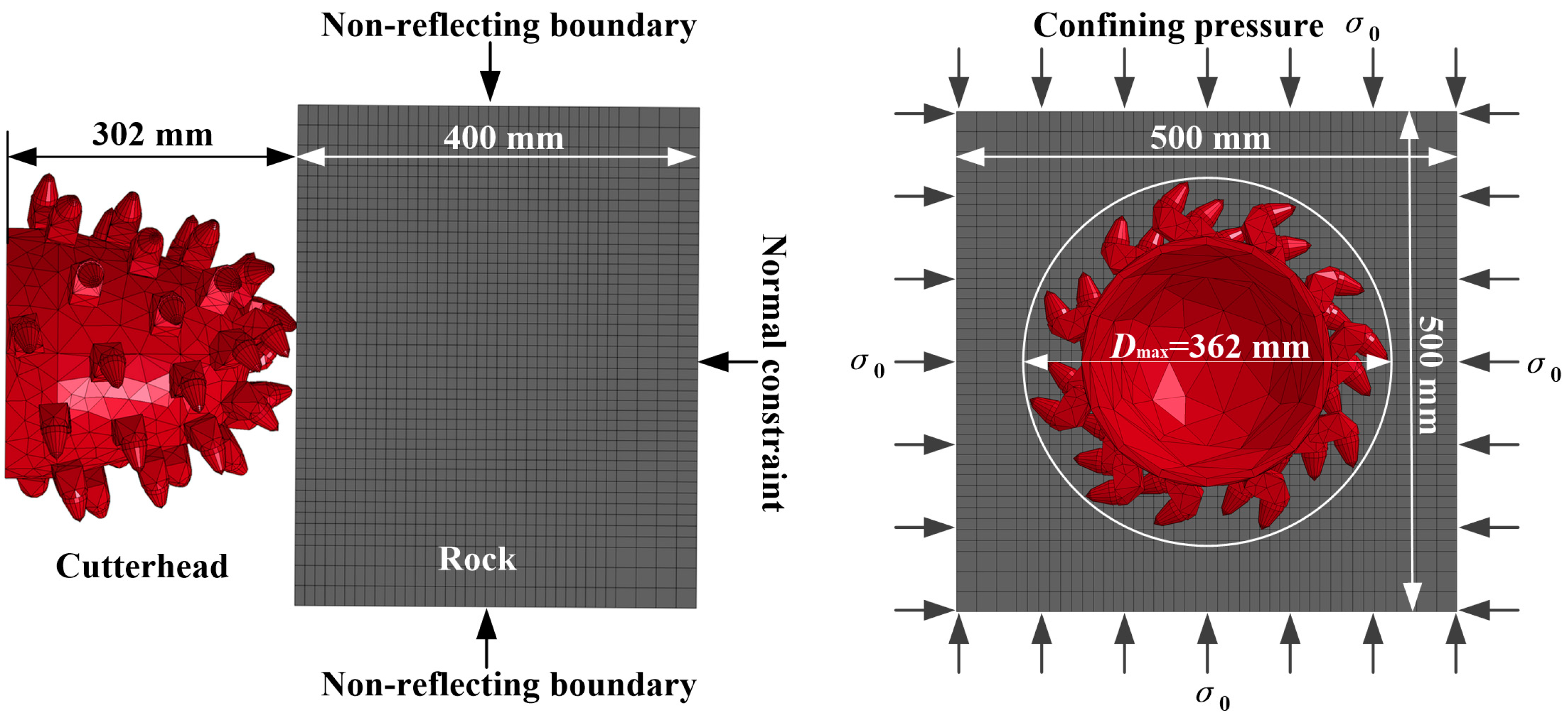
3.1. Material Model and Boundary Conditions

The cutterhead is regarded as a rigid body, with the MAT 020 (Rigid) in LS-DYNA chosen for the material model of the cutterhead [32]. There have been a good number of models developed for the rock and concrete. The MAT 145 (Schwer_Murray_Cap_Model) in LS-DYNA is an advanced constitutive model for geomaterials with a sound theoretical background [33,34,35]. However, it has not been as popular as those simple material models, because of the complexity of the model with 42 material parameters involved. A wealth of material model parameters can make the simulation more realistic, and thus the MAT 145 is adopted as the material model for the rock. The main parameters of the rock and cutterhead in the numerical models are shown in Table 1.
Figure 1 depicts the finite element model of rock breaking by the cutterhead. The rock model is 500 mm high by 500 mm wide by 400 mm thick, while the cutterhead is 302 mm long and up to 362 mm in diameter. There are 64,656 elements for the rock without holes, while the cutterhead consists of 20,827 elements. To avoid the influence of the reflected stress wave, non-reflecting boundary conditions are applied at the upper, bottom, left, right, and back boundaries of the rock model, respectively. To consider the effect of confining pressure σ0, the corresponding pressures are set at the four sides of the rock model, while the normal constraint condition is set at the back boundary of the rock model.

3.2. Contact and Failure Criterion

For the cutterhead-rock contact, the “ERODING_NODES_TO_SURFACE” contact type is chosen [36]. The material model itself has a failure criterion. Damage is defined within the framework of continuous damage mechanics and the damage index (DI) is defined to determine whether damage loading occurs or not [37]. The program was able to automatically calculate the stress and damage status of each element after each loading step. When an element is subjected to substantial stress and its damage index (DI) reaches 1, it would lose all its strength and suitability. Following this, it would be regarded as invalid and would be removed from the model immediately. Meanwhile, the program would also automatically redefine the contact relationship between the cutterhead and rock. Additionally, the failure criterions are defined using the keyword of “MAT_ADD_EROSION” to ensure a more reasonable damage process of rock. Specifically, failure criterions based on the effective plastic strain [37] and effective stress [38] are employed to delete an excessively deformed element in the simulation. When the effective plastic strain reaches 0.15 (determined through sensitivity studies) [36] or the effective stress reaches 30 MPa (based on the rock strength), the excessively deformed element of rock is removed from the model.

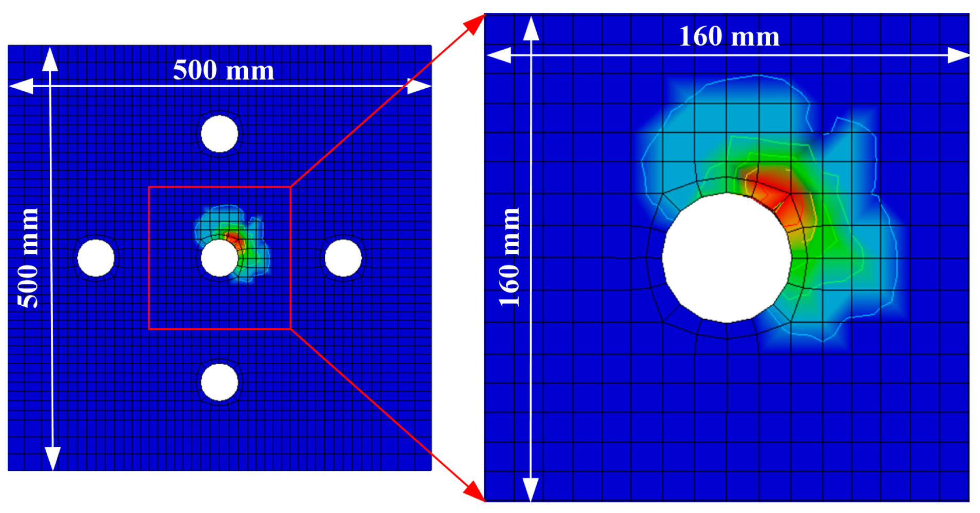
3.3. Rock Model Design

To investigate the effect of the number of holes on rock-breaking performance, the rock models containing a different number of holes are designed, as shown in Figure 2. The hole ratio η is defined as η = 100 × n× (Dhole/Dmax)2%, where n is the number of the hole, Dhole is the diameter of the hole and Dmax is the maximum diameter of the cutterhead. For example, if the hole ratio η is up to 50%, there will be dense holes in the rock and the cutting efficiency of cutterhead will be high, although it is apparently time-consuming and costly to drill dense holes. In this paper, the maximum value of the hole ratio η is controlled to remain around 20% and the diameter of the hole is chosen as 45 mm, with the holes distributed in the center and along the circle with a diameter of 292 mm. The number of holes is 1, 5, 9, and 13, respectively. These correspond to the hole ratio η of 1.6%, 7.7%, 13.9%, and 20.1%, respectively.
To discuss the effect of hole size on rock-breaking performance, a sketch of the rock model is shown in Figure 3. For each rock model, there are four holes evenly distributed along the circle with a diameter of 292 mm and one hole distributed in the center. The diameters of the holes are 35, 45, 55, and 65 mm, respectively. The corresponding hole ratios η are 4.7%, 7.7%, 11.5%, and 16.1%, respectively.

3.4. Motion Parameters of Cutterhead

In the simulations, the advance speeds are controlled at 400 mm/min and each advancing process occurs for approximately 50 s to ensure that the entire cutterhead is involved in the rock fragmentation process. The rotational speed of the cutterhead is 80 RPM (revolutions per minute). By maintaining a constant advance speed and rotation, the influence of holes and confining pressures on rock-breaking performance are computed and compared.

4. Verification of the Numerical Model

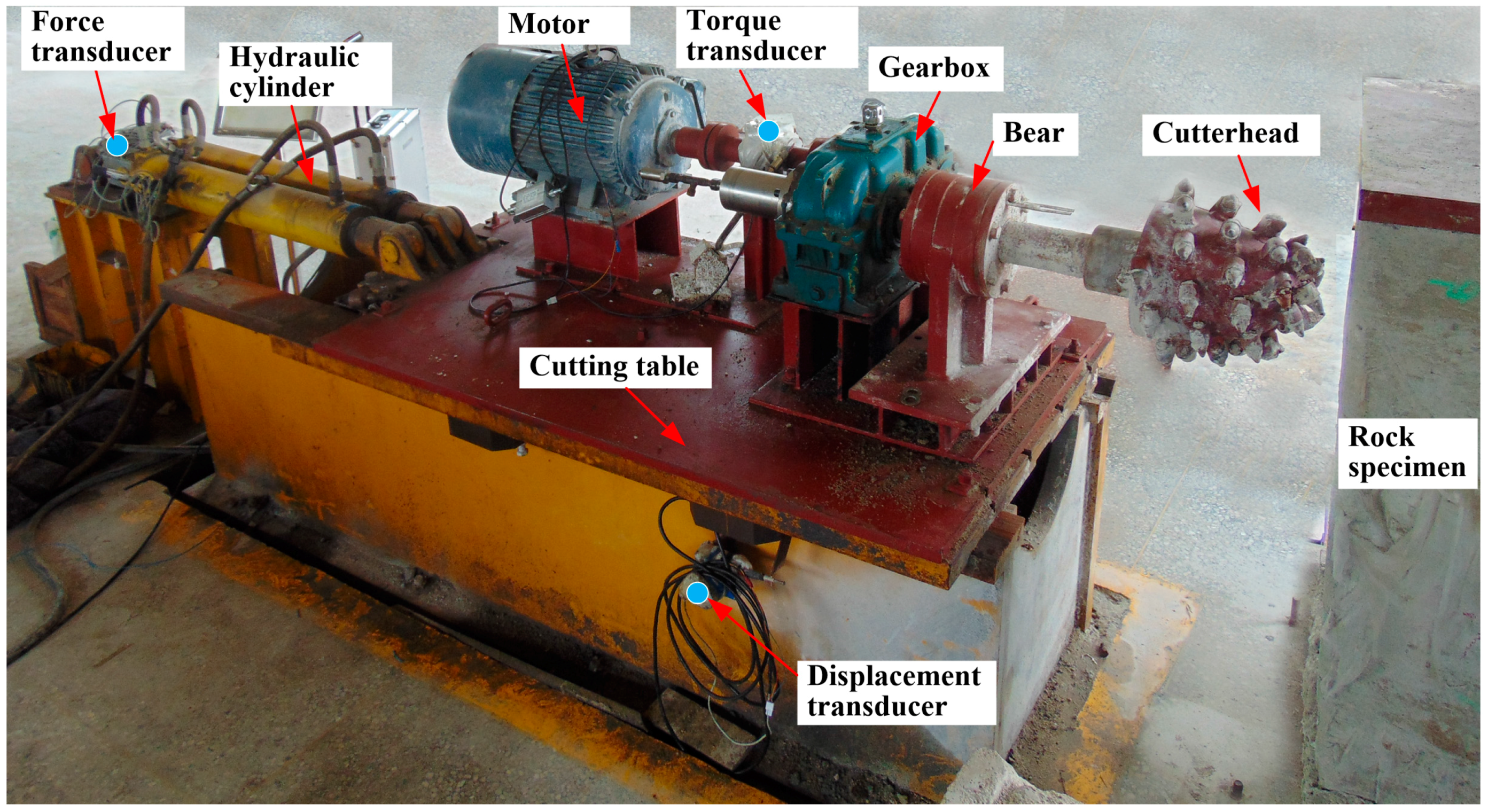
4.1. Experiment Procedures

Figure 4 illustrates the rock-breaking platform used in the study. It includes a cutting table on which the motor, gearbox, bear, and cutterhead are mounted. Two hydraulic cylinders are used to move the table along the tracks. The thrust force of the cylinder is monitored using a force transducer, while the cutting torque of the cutterhead is measured by a torque transducer. A displacement transducer is installed on the table to measure the movements of the cutterhead. The transducers are connected to the data acquisition system, which monitors and records the thrust force, torque, and cutterhead displacement.

4.2. Comparison between Experimental and Numerical Results

To validate the developed rock-breaking model, the comparisons were made between experimental and numerical results. Figure 5 presents the graphs of cutting torques and thrust forces against different numbers of holes without the confining pressure. It is evident that the torque and the thrust force of the roadheaders increase over time. The trends of the curves for the rock without holes are similar to those in the rock with holes. The average cutting torques and thrust forces during the whole advancing process are computed to analyze how the holes in the rock affect the cutting performance of the roadheader.
The experimental average cutting torques of 0, 1, 5, and 13 holes are 1280, 1150, 1080, and 774 N·m, respectively. Meanwhile, the average thrust forces drop from 7280 to 6500, 5510, and 4210 N. In the experiments, the reductions in torque and force for the rock containing one hole are 10.2% and 16.9%, respectively. The corresponding reductions in these values for the rock containing five holes are 15.6% and 29.5%, respectively, and for the rock containing 13 holes are 39.5% and 46.1%, respectively. The four numerical curves are considerably consistent with the experimental curves. For one hole, the decrease in numerical values of torque and force are 12.6% and 22.1%, respectively. Moreover, for five holes, the corresponding decrease in these values are 18.5% and 27.1%, and for 13 holes, the corresponding decrease in these values are 32.3% and 48.5%, which indicates satisfactory consistency with the experimental data.

5. Numerical Results and Discussion

5.1. Effect of Hole Number on Rock Fragmentation

The rock breaking of the roadheader is the result of the interaction between the cutterhead and rock. Once the picks of cutterhead makes contact with the rock, and stress appears in the rock. Moreover, the stress causes elastic deformation, plastic deformation, damage, and even breakage of the rock. Thus, a larger stress means that more serious damage is inflicted on the rock, making this rock easier to be cut in the next cutting step. Figure 6 shows the Von Mises effective stress contours of rocks containing a different number of holes at the advance time of 25 s. It should be noted that there are evident phenomena of stress concentration seen around the holes, with this stress concentration becoming more obvious with an increase in the number of holes.
Figure 7 presents the effective stress contours for a cross-section of the rock center. As shown in Figure 7a, the radial length between the cutting line and the stress termination line is defined as the stress depth h. The stress depth increases with an increase in the number of holes. Specifically, the average stress depth increases from 21 mm (0 hole) to approximately 53 mm (13 holes). Moreover, there is an active zone around each hole and the values for the stress depth near the holes are greater than those far from the holes. Following this, the active zones are superimposed and become coupled to each other, which leads to the efficient expansion of stress in the whole rock.
To analyze how the hole number affects the cutting performance, the average cutting torque T and thrust force F are computed and compared, with the results shown in Figure 8. It shows that the cutting torque and thrust force decrease remarkably with an increase in the number of holes. Specifically, the cutting torque decreases from 1158 N·m (without holes) to 714 N·m (with 13 holes), while the thrust force drops from 8688 to 4474 N. These correspond to a decrease rate of 38.5% and 48.5%, respectively. At the same time, the hole ratio η of the rock specimen containing 13 holes is 20.1%. We defined the decrease in torque and force rate as εT and εF, while we labelled the ratios of εT and εF to the hole ratio η as the normalized effect indexes ηT and ηF. In addition, for the rocks containing one to 13 holes, their ηT are 7.88, 2.40, 1.86, and 1.91, while the ηF are 13.8, 3.52, 2.75, and 2.41, respectively.
The specific energy (SE) is one of the most important indexes to measure the rock-breaking performance of mechanical excavations. It is defined as the energy required for the fragmentation of a unit volume of rock. Advancement is the most energy-intensive mode for a roadheader. According to Fowell and McFeat-Smith [39], the specific energy required for advancement is approximately three times that for traversing. In the advancement mode of the cutterhead, the specific energy can be computed with the following formula:
SE = W T + W F V = P t + F l V = 1 V ( 0 t v R T ( t ) d t 9550 + 0 l F ( L ) d l 3 . 6 × 10 6 )
where SE is the specific energy (kW·h/m3); WT is the work performed by the cutting torque (kW·h); WF is the work performed by the thrust force (kW·h); V is the volume of the broken rock (m3); P is the cutting power [23]; v R is the cutterhead rotation speed (RPM); T is the cutting torque (N·m); F is the thrust force (N); t is the cutterhead advance time (h); and l is the cutterhead advance length (m).
Figure 9 shows the influence of the number of holes on the specific energy of rock breaking. The curve trend of the specific energy is similar to the trend for the cutting torque, which results from the fact that the energy consumed by the rotary cutting is far greater than that used for advancement. The decrease in energy rates εE of the rock containing one to 13 holes are 12.7%, 19.3%, 25.9%, and 38.4%. Moreover, the corresponding normalized effect indexes ηE are 7.94, 2.51, 1.87, and 1.91, respectively.

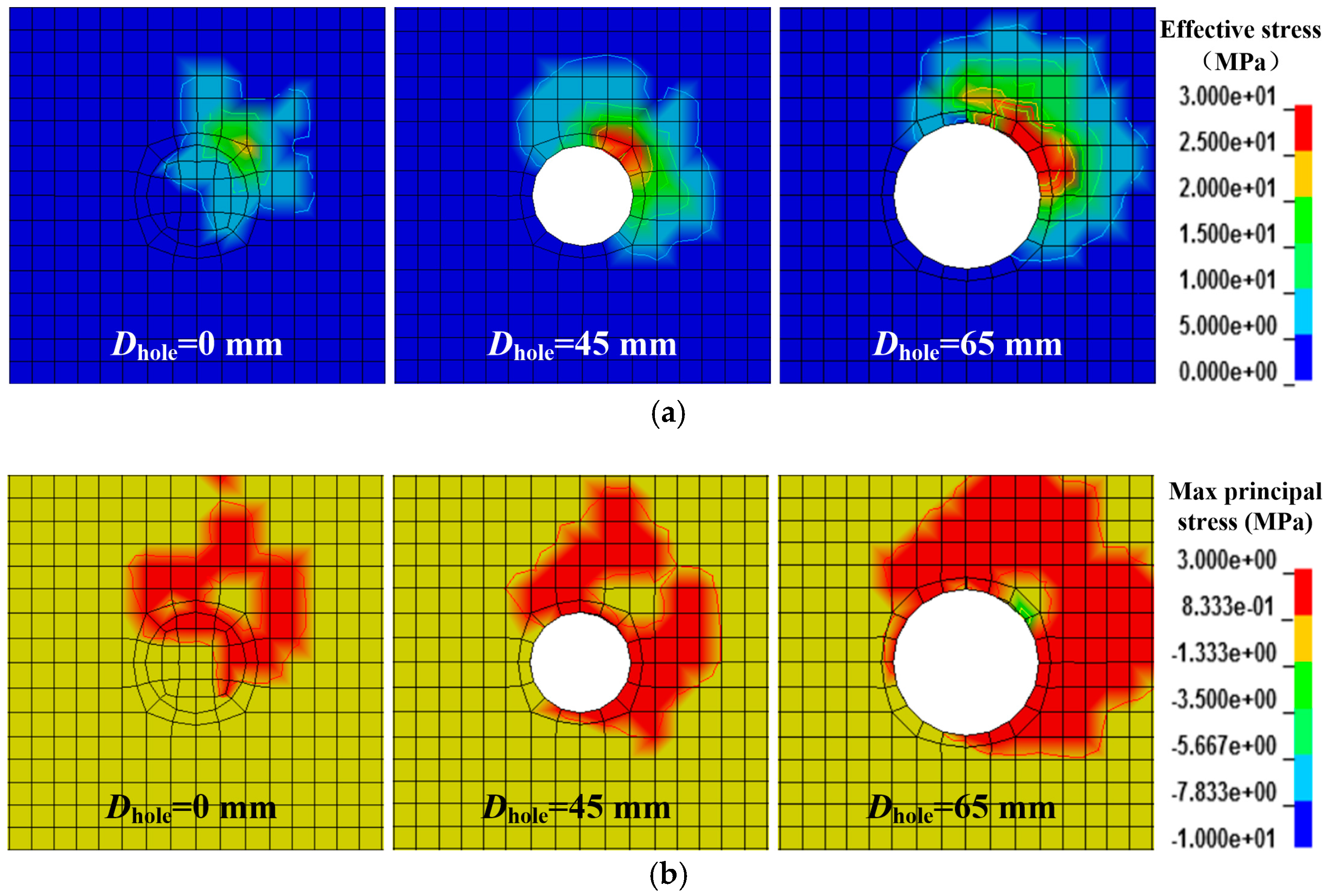
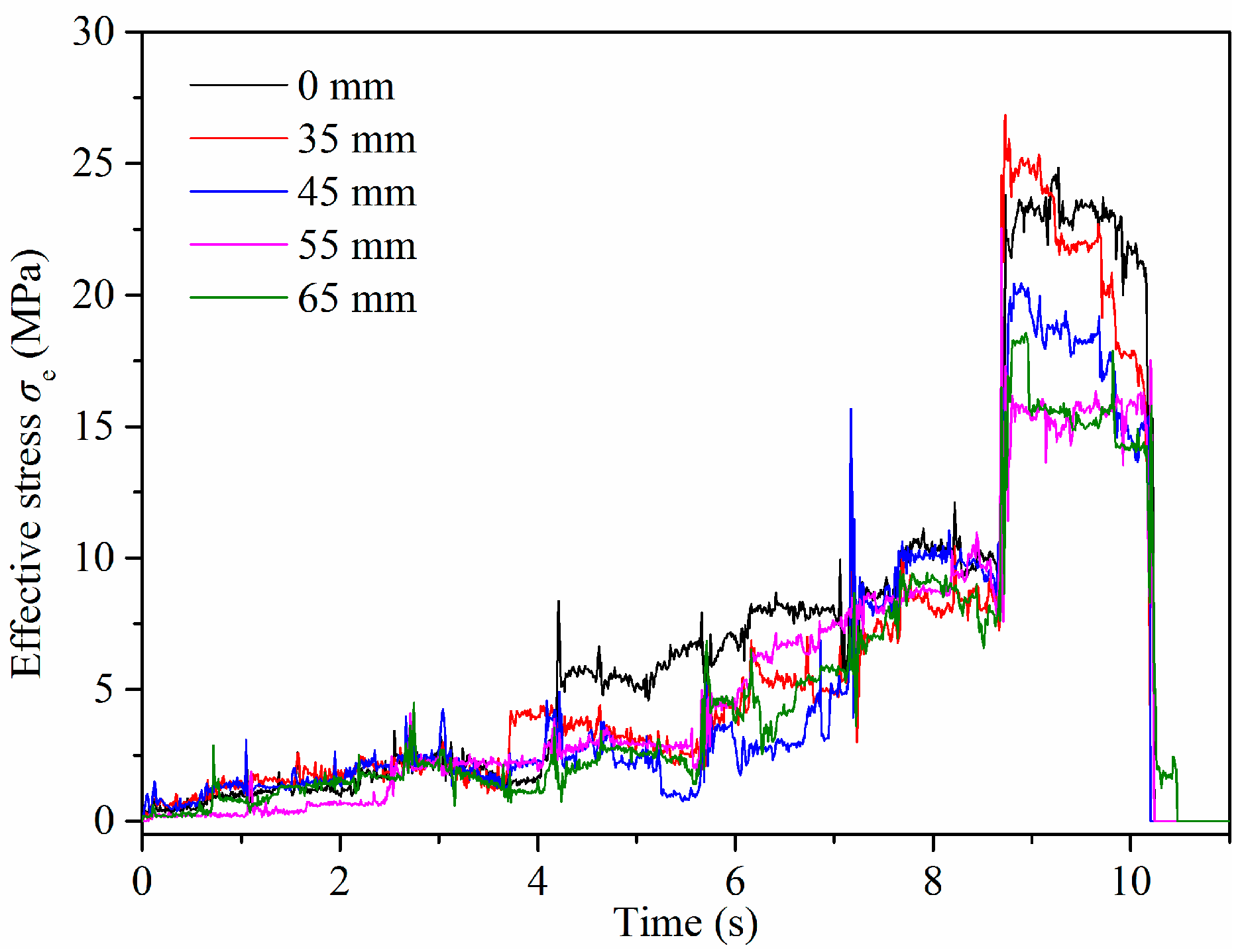
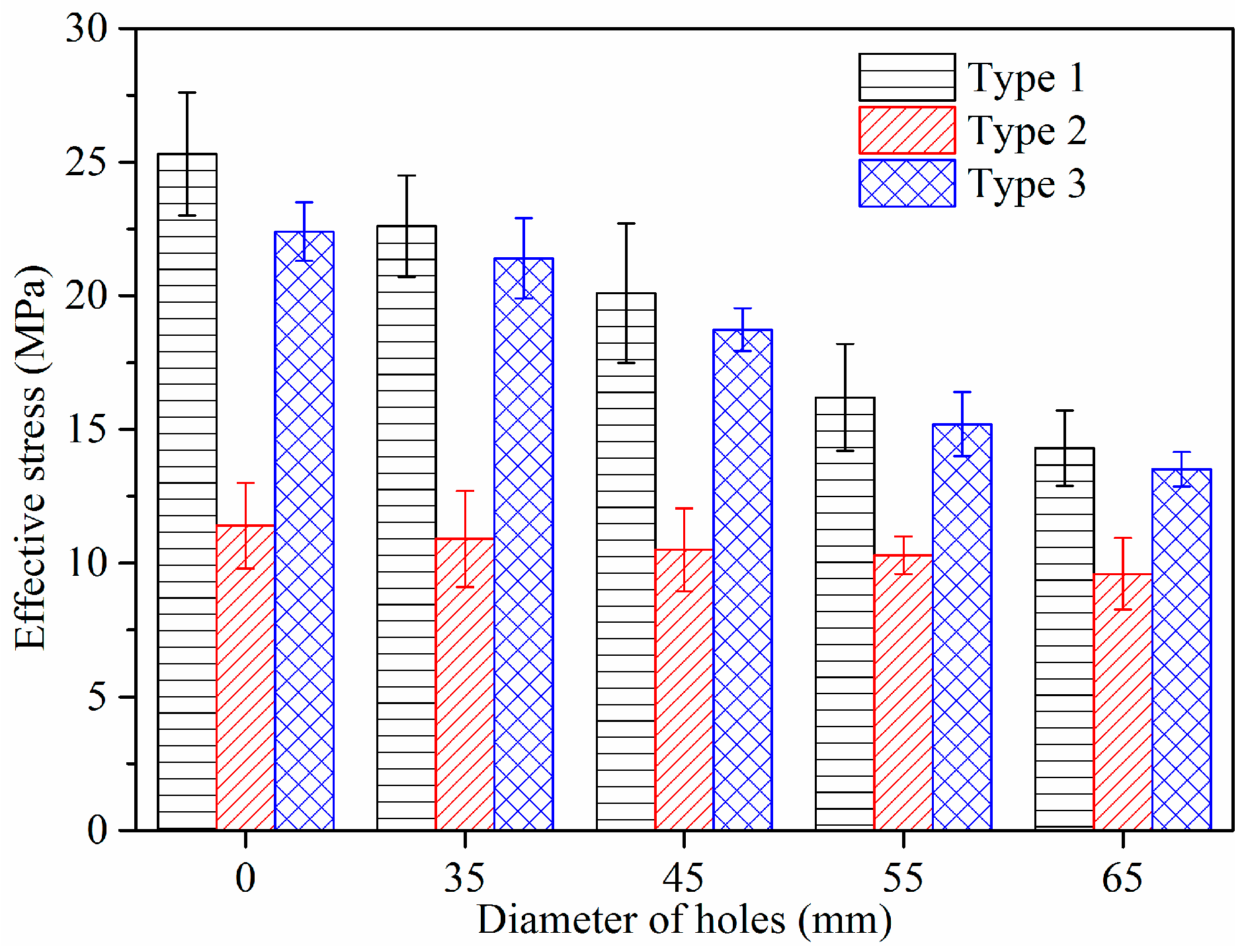
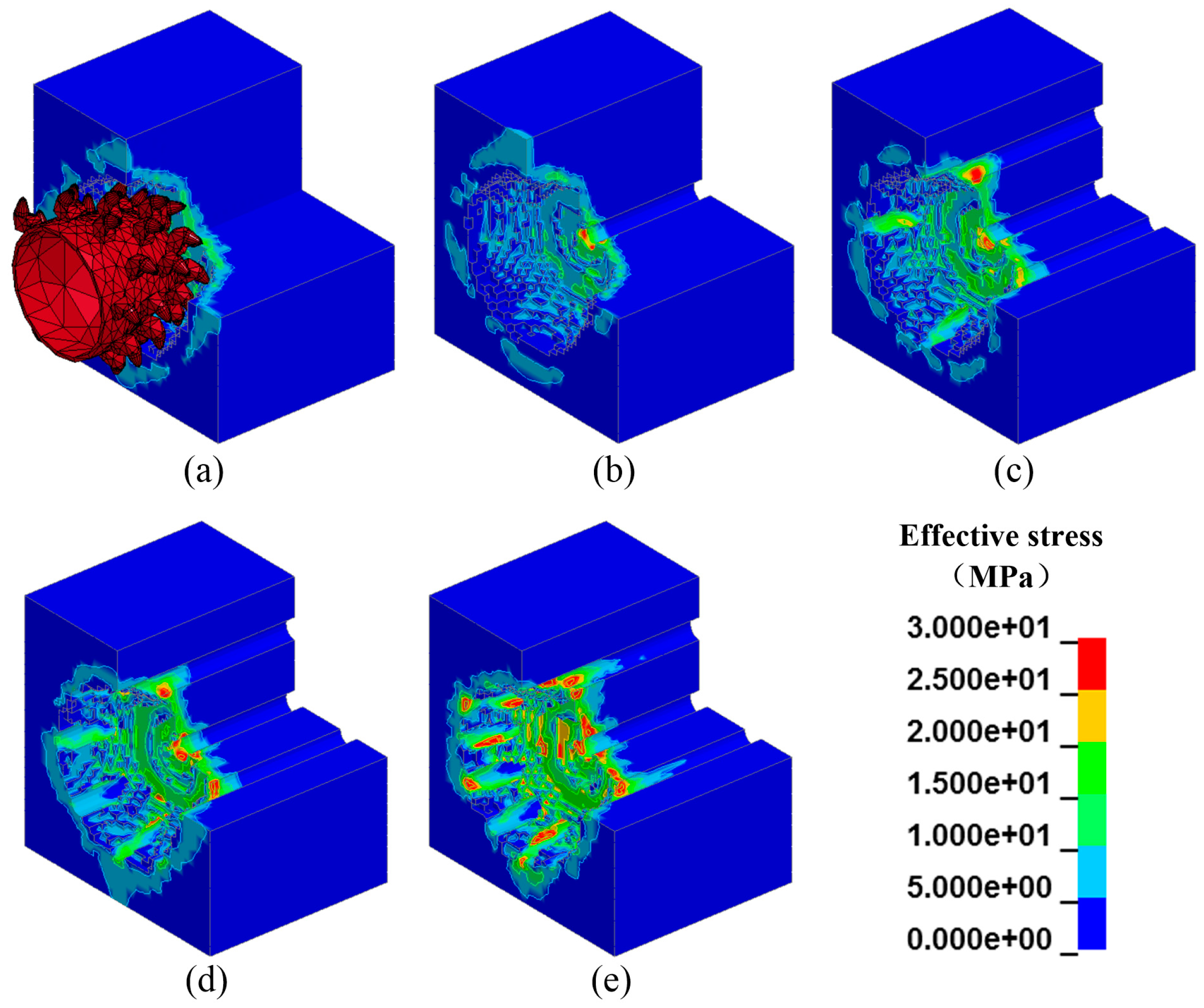
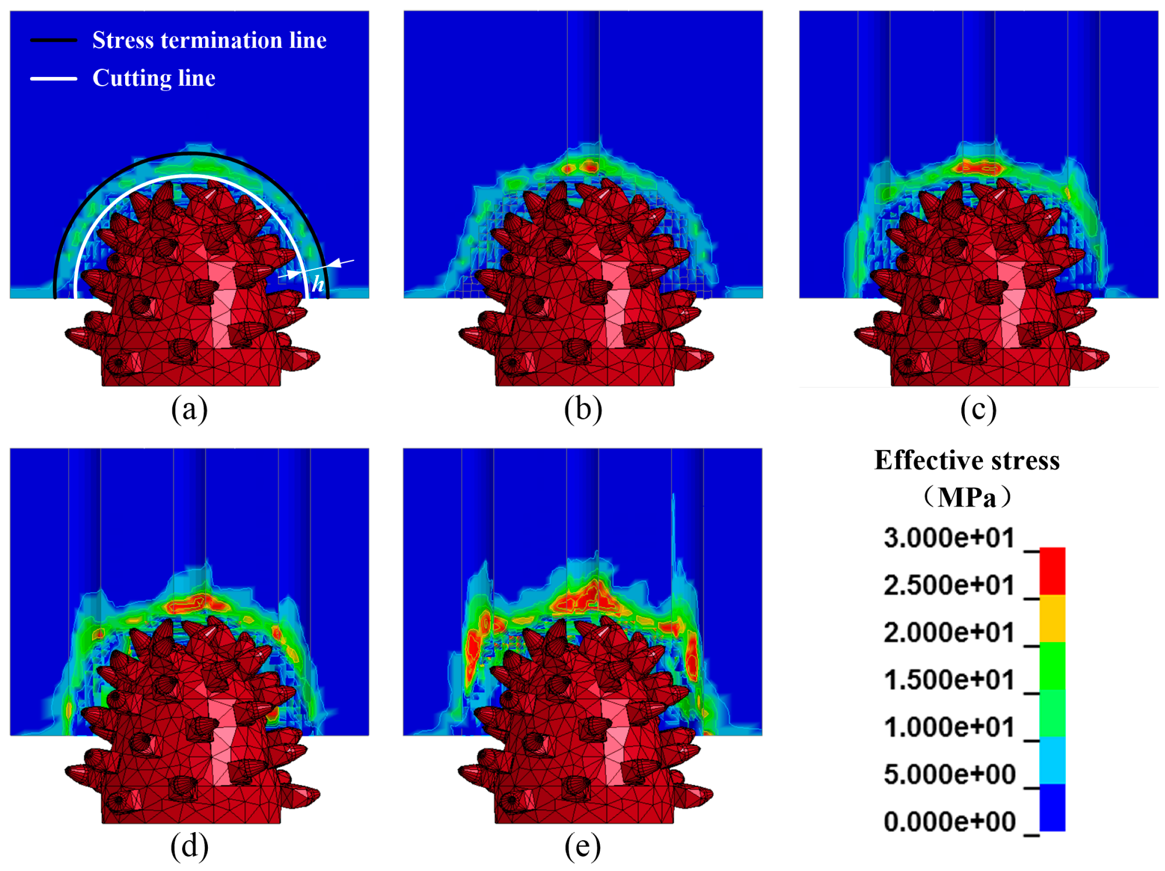
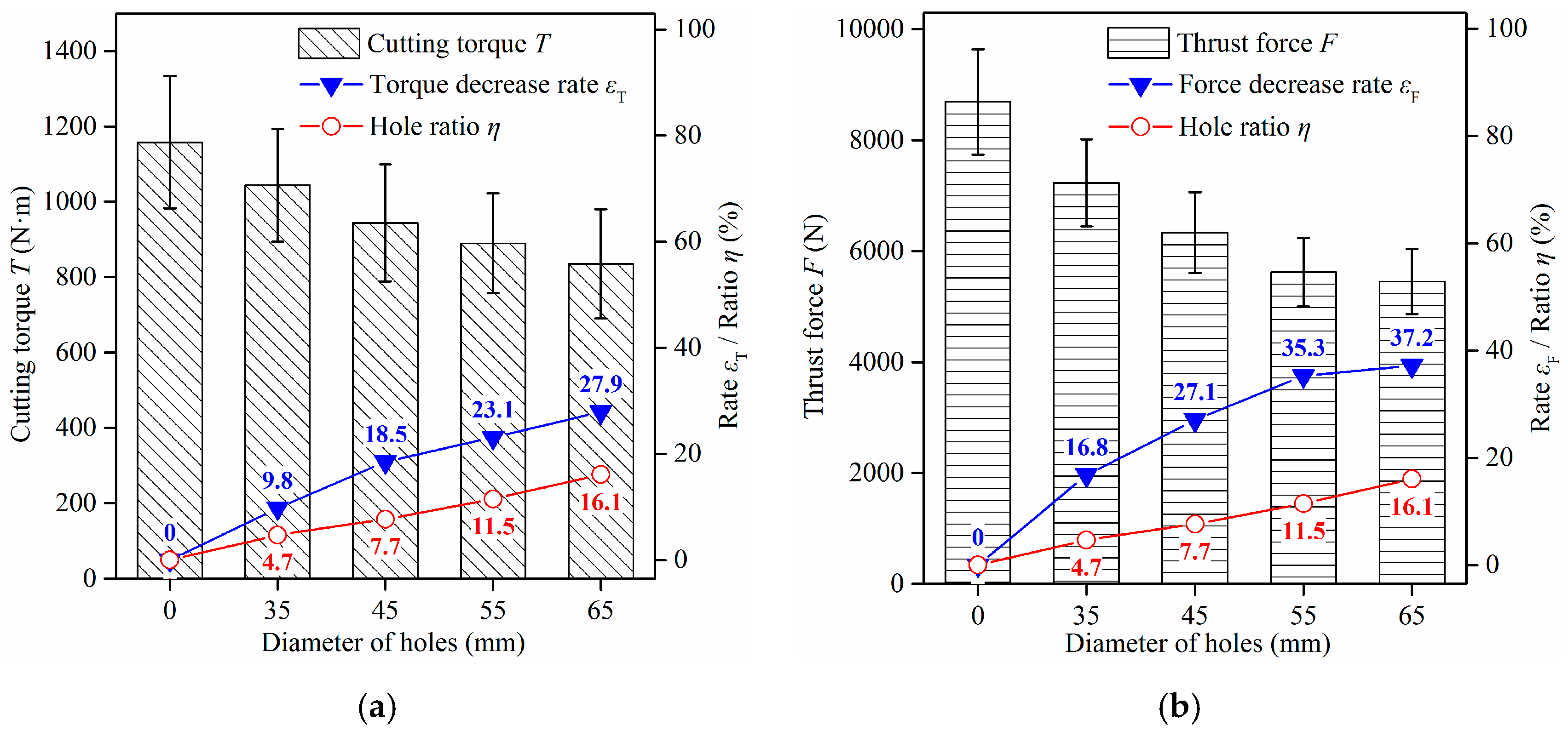
5.2. Effect of Hole Size on Rock Fragmentation

Figure 10 illustrates the effective stress contours of the front face of a rock containing five holes at the advance time of 0.1 s. To investigate how the diameter of the hole affects the rock-breaking performance, Figure 11 shows the effective stress and the maximum principal stress contours of rocks containing holes with different diameters. Figure 11a shows that stress appears on the rock once the pick (not shown in Figure 11) makes contact with the rock, with the position of the maximum value being located around the contact zone between the pick and rock. Moreover, the effective stress increases with an increase in the diameter of holes, with stress concentration phenomena occurring around the holes. Figure 11b shows the distribution of the maximum principal stress (a positive value indicates tensile status and a negative value indicates compressive status). It should be noted that when the pick tip contacts the rock, the rock elements that are in contact with the pick are subjected to the compressive stress and generate a squeeze zone. Meanwhile, the elements around the squeeze zone have a tensile status and form a tensile stress zone (red color). With an increase in the diameter of the hole, the influence of the free surface and the area of the tensile stress zone both increase. The tensile strength of rock is only 10% of its compressive strength. Thus, a greater tensile stress zone means that it is easier to break the rock.
To investigate the effect of hole diameter on different elements, three types of elements for the cross-section (50 mm from the front face of the rock) are selected and shown in Figure 12. Moreover, Figure 13 shows the effective stress of Elements 1, 2, and 3 during the breaking process. Between the three types, Element 1 is closest to the center hole and is destroyed first at the advance time of 7.7 s, which is followed by Element 2 at 9.4 s and Element 3 at 10.2 s.
Figure 14 presents the effective stress of Element 3 in rocks with different hole diameters. The change in the trends of different curves are similar. At the beginning, the cutterhead is far from Element 3 with a small effective stress of Element 3. With the advancement of the cutterhead, the effective stress increases continuously. However, the stress rises rapidly at the time of around 8.7 s, before decreasing sharply at approximately 10.2 s. This indicates that the rock element is mainly destroyed during this period of time, which is called the damage stage.
To analyze the influence of hole size on rock breakage, the average effective stress of the elements during the damage stage is calculated. As shown in Figure 12, each type consists of four elements, with the mean values of the four elements computed and shown in Figure 15. For the rock without holes, the mean effective stress of Type 1, 2, and 3 is 25.3, 11.4, and 22.4 MPa, respectively. The cutterhead first makes contact with the elements of Type 1 and there is no free surface for these elements. Thus, the elements of Type 1 are difficult to break and their mean effective stress is high. After the breakage of Type 1, the broken pit provides the free surface for Type 2, so the mean value of Type 2 is reduced. There is a bigger broken pit after the breakage of Type 2. However, the mean value of Type 3 increases compared with that of Type 2. The reason for this is that the elements of Type 3 are destroyed by picks that are installed with a larger rotation radius, which will lead to a faster line cutting speed and greater stress. Thus, the elements are under the influence of the free surface and cutting speed. Specifically, when the diameter of the hole is 65 mm, the mean effective stress of Type 1, 2, and 3 is 14.3, 9.6, and 13.5 MPa, respectively. This was reduced by 43.4%, 15.8%, and 39.7%, compared to the elements in the rock without holes.
Figure 16 shows the average cutting torque and thrust force of rocks with different hole diameters. With an increase in the diameter, the cutting torque and thrust force decrease gradually. Specifically, the cutting torque decreases from 1158 N·m (Dhole = 0 mm) to 835 N·m (Dhole = 65 mm) with a decrease of 27.9%. Meanwhile, the corresponding thrust force drops from 8688 N to 5452 N with a decrease of 37.2%.
Figure 17 shows the influence of the diameter of holes on the specific energy of rock fragmentation. The changing trend of the specific energy is similar to the trend of the cutting torque, which results from the fact that the energy consumed by the rotary cutting is far greater than the energy consumed in the advancement. The decrease in the energy rates εE of rock with the diameter of 35, 45, 55, and 65 mm are 10.5%, 19.3%, 24.6%, and 28.1%, respectively. Moreover, the corresponding normalized effect indexes ηE are 2.23, 2.51, 2.14, and 1.75, respectively. It is evident that larger holes allow for lower energy consumption. However, it also means that more time and energy has to be spent on the drilling of holes. Therefore, an adequate design of holes should be chosen by considering the effectiveness of energy. In this work, the rock containing holes with a diameter of 45 mm is optimal for the cutterhead.

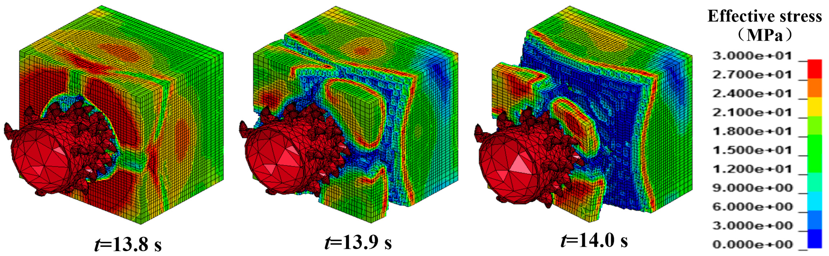
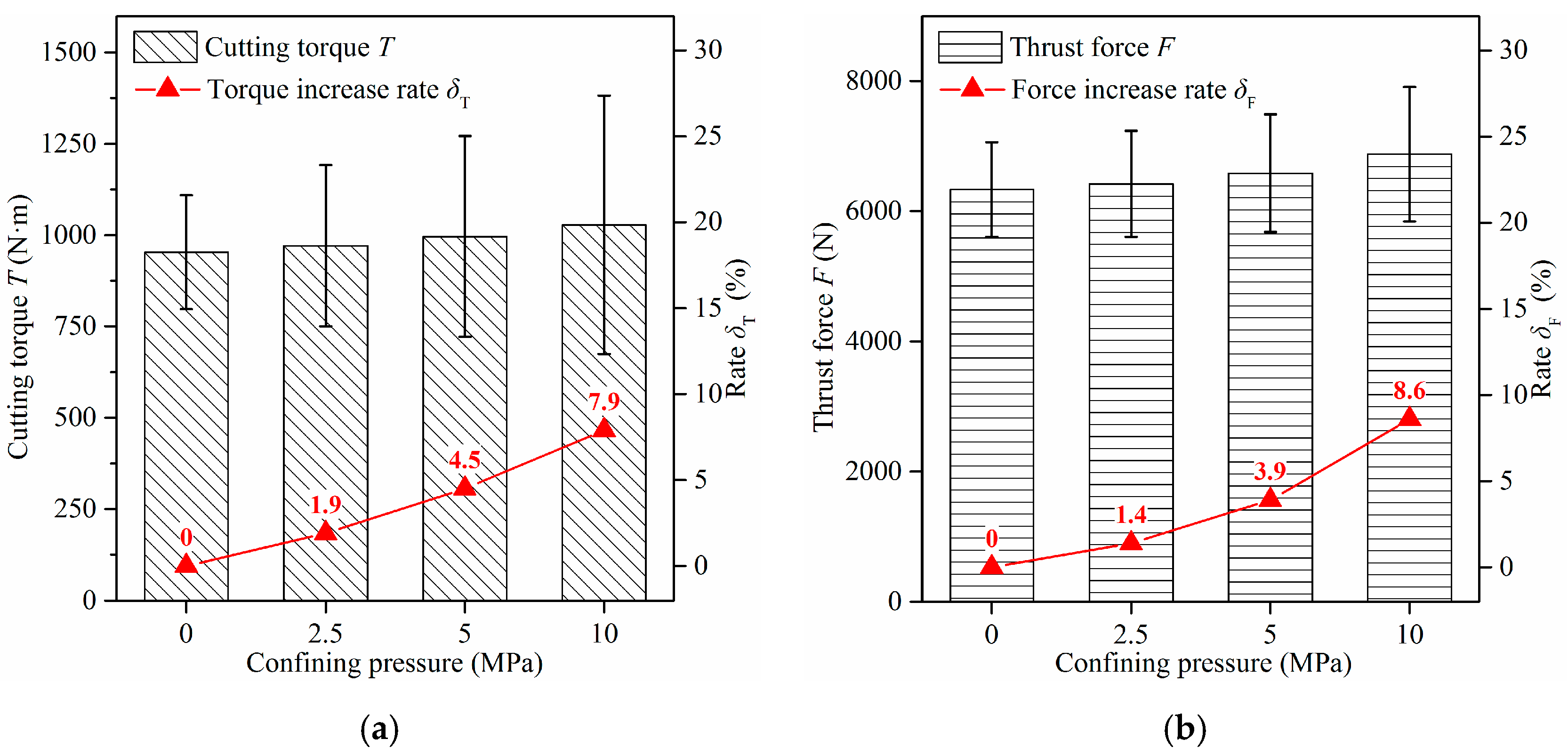
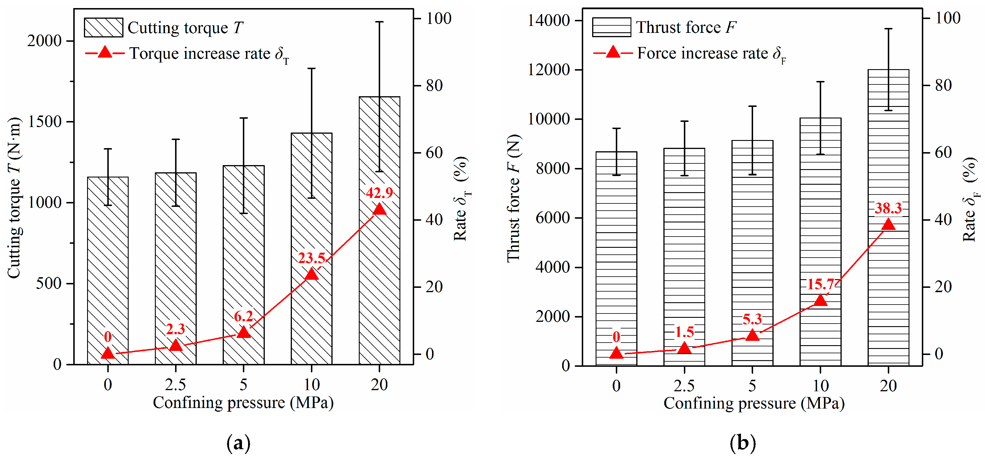
5.3. Effect of Confining Pressure on Rock Fragmentation

Figure 18 shows the cutting torque and thrust force of rock without holes under different confining pressures. Specifically, the cutting torque increases slowly under a low confining pressure, although this rises rapidly under a high confining pressure. For example, the increment of the torque is 6.2% when the pressure increases from 0 to 5 MPa, while an increment of 23.5% is obtained when the pressure increases from 0 to 10 MPa. In addition, the thrust force shows a similar change in its trend as the cutting torque. This indicates that the effect of high confining pressure on cutting performance is more evident than that of low confining pressure. Thus, the confining pressure of 10 MPa is selected for studying the effect of hole number on rock breakage under confining pressure. The Von Mises effective stress contours of rocks containing a different number of holes are shown in Figure 19.
Compared with the contours without confining pressure, as shown in Figure 6, the contours under the confining pressure of 10 MPa are more complex. The stress contours are due to the combination of the effect of the confining pressure and the impact of the cutting process. Specifically, comparing Figure 19c to Figure 6c, the stress concentration phenomena around the holes are more obvious in Figure 19c, due to the superimposition of the stresses on the confining pressure and the cutting force.
To study how the cutting performances are affected by the hole number under the confining pressure of 10 MPa, the average cutting torque T and thrust force F are shown in Figure 20. With an increase in the number of holes, the cutting torque and thrust force is reduced. Specifically, the decrease in the torque and force are 39.8% and 41.1% in the rock containing 13 holes, respectively. Moreover, for the rocks containing one to 13 holes, their ηT are 12.69, 3.65, 2.35, and 1.98, while the corresponding ηF are 15.38, 4.09, 2.85, and 2.04, respectively. It should be noted that more holes can result in lower torque and force. However, the normalized effect indexes ηT and ηF decrease with an increased number of holes. For the rock containing five holes, there is a decrease of approximately 30% in the torque and force, with relatively high normalized effect indexes ηT and ηF. Thus, the rock with five holes is optimal for the cutterhead considering the effectiveness of energy.
Figure 21 and Figure 22 show the effective stress and the maximum principal stress contours of rocks containing five holes under the different confining pressures at the advance time of 0.1 s. Figure 21 shows that the stress in the rocks increases with an increase in the confining pressure. For example, the background of rock without the confining pressure is navy blue, which indicates that the effective stress belongs to a pressure of 0–3 MPa. The background of rock under the confining pressure of 10 MPa is light blue, which means that the effective stress belongs to a pressure of 9–12 MPa. There are stress concentration phenomena around the contact zone between the pick and rock. Furthermore, there is an obvious stress concentration phenomenon around the holes with an increase in the confining pressure. Figure 22 shows that the elements around the squeeze zone have a tensile status and form a tensile stress zone (red color). Moreover, the area of the tensile stress zone decreases with an increase in the confining pressure, which indicates that the propagation of tensile stress is limited by the confining pressure. Therefore, the rock under a high confining pressure is difficult to cut and it results in an increase in cutting torque and thrust force, as shown in Figure 18.
Figure 23 shows the fragmentation process of rock containing five holes under the confining pressure of 10 MPa. With the advancement of the cutterhead, the effective stress in the rock changes significantly. For example, at the advance time of 10 s, the elements on the side of the broken pit are green (with an effective stress from 12 to 15 MPa), while the elements on the side of the broken pit are red at an advance time of 45 s (with effective stress from 27 to 30 MPa). This indicates that the effective stress is constantly superimposed during the advancement process, which will lead to the subsequent rock element being easier to destroy.
Figure 24 shows the fragmentation process of the rock containing five holes under the confining pressure of 20 MPa. At the advancement time of 13.8 s, several main cracks began to appear in the rock. With the advancement of the cutterhead, the elements along the main cracks are constantly being destroyed and deleted. At the same time, the large chips are removed from the rock until the advance time of 14 s. When the confining pressure reaches 20 MPa, there is evident stress concentration around the cutterhead. The interactions between the free surface of holes and the rock boundaries lead to the failure of rock. This also explains why the rock burst occurs during the excavation of the chamber in the rock under a high confining pressure.
As the large chip failure occurs in the rock under the confining pressure of 20 MPa, the curves of the torque and force are not continuous from the advance time of 14 s. Thus, Figure 25 only shows the average torque and force of rock under the confining pressure from 0 to 10 MPa. As the confining pressure increases, the cutting torque and thrust force increase. Moreover, the increase in the rock with five holes is smaller than that of rock without holes (shown in Figure 18). Specifically, under the confining pressure of 10 MPa, the increases in the torque and force are 23.5% and 15.7%, respectively, in the rock without holes, while the corresponding increases in the rock with five holes are 7.9% and 8.6%, respectively. This indicates that the large torque and force caused by the high confining pressure can be reduced by drilling holes in the rock.
The rock fragmentation process using the cutterhead is also a process of energy dissipation. Generally, during the advancement process of the cutterhead, the energy dissipation can be divided into several modes: elastic strain energy, plastic strain energy, brittle failure energy, ductile failure energy, thermal energy, and so on [11]. Specifically, two energy modes are mainly responsible for the rock fragmentation: the brittle failure energy consumed by tensile failure as well as the ductile failure energy consumed by shear and compressive failure. As the tensile strength of rock is smaller than the shear and compressive strength, the energy consumed by the brittle failure is lower than that of the ductile failure. With an increase in the confining pressure, the failure behavior of rock transfers from a brittle mode to the semi-brittle and ductile modes, which needs more energy to break the rock. However, the free surface provided by the holes can weaken the effect of the confining pressure and can lead to the brittle failure of rock around the holes.

6. Conclusions

In this paper, a series of numerical investigations are carried out to analyze the dynamic characteristics of the roadheader for breaking a rock containing different numbers and sizes of holes under different confining pressures. A detailed discussion is presented on the cutting torque, thrust force, specific energy, and failure behavior during the cutting process. The following conclusions can be drawn.
The specific energy decreases with an increase in the number and size of holes, while the decrease in the energy rates of the rock containing a different number (1, 5, 9, and 13) of holes is 12.7%, 17.6%, 25.9%, and 38.4%, respectively. Meanwhile, the decrease in the energy rates of a rock with different hole diameters (35, 45, 55, and 65 mm) are 10.5%, 19.3%, 24.6%, and 28.1%, respectively. The cutting torque and thrust force increase slowly under the low confining pressure, although this rises rapidly under the high confining pressure. For example, the increase in the torque is 6.2% when the pressure increases from 0 to 5 MPa, while an increment of 23.5% is obtained when the pressure increases from 0 to 10 MPa. Under the confining pressure of 10 MPa, the increases in the torque and force of the rock without holes are 23.5% and 15.7%, respectively, while the corresponding increases in the rock with five holes are 7.9% and 8.6%, respectively. This indicates that the high energy consumption caused by the high confining pressure can be reduced by drilling holes in the rock.
The rock fragmentation process by the cutterhead is a process of energy dissipation. Two energy modes are mainly responsible for the rock fragmentation: the brittle failure energy consumed by tensile failure as well as the ductile failure energy consumed by shear and compressive failure. With an increase in the confining pressure, the failure behavior of the rock transfers from a brittle mode to semi-brittle and ductile modes, which requires more energy to break the rock. However, the free surface provided by the holes can weaken the effect of the confining pressure and can lead to the brittle failure of rock around the holes.

Acknowledgments

The authors gratefully acknowledge the support provided by the Priority Academic Program Development of Jiangsu High Education Institute of China, National Natural Science Foundation of China (No. 51375478) and China Scholarship Council.

Author Contributions

Changlong Du and Zenghui Liu conceived and designed the experiments; Hongxiang Jiang and Zenghui Liu performed the experiments; Kai Liu and Zenghui Liu analyzed the simulations; Zenghui Liu wrote the paper.

Conflicts of Interest

The authors declare no conflict of interest.

References

  1. Lu, Y.; Xiao, S.; Ge, Z.; Zhou, Z.; Deng, K. Rock-breaking properties of multi-nozzle bits for tree-type drilling in underground coal mines. Energies 2016, 9, 249. [Google Scholar] [CrossRef]
  2. He, M. Present State and Perspective of Rock Mechanics in Deep Mining Engineering; Science Press Beijing: Beijing, China, 2004; pp. 88–94. [Google Scholar]
  3. Wang, Z.; Dou, L.; Li, J.; Kang, K.; Feng, L. Numerical investigation of damage risks of roadway surrounding rocks under oblique incident dynamic loads. Shock Vib. 2017, 2017, 6298372. [Google Scholar] [CrossRef]
  4. Neil, D.; Ozdemir, L. Considerations for Development of Hard Rock Roadheaders. Available online: http://emi.mines.edu/UserFiles/File/earthMechanics/roadheader/roadheader1.pdf (accessed on 25 July 2017).
  5. Bilgin, N.; Copur, H.; Balci, C. Mechanical Excavation in Mining and Civil Industries; CRC Press: Boca Raton, FL, USA, 2013. [Google Scholar]
  6. Bilgin, N.; Dincer, T.; Copur, H.; Erdogan, M. Some geological and geotechnical factors affecting the performance of a roadheader in an inclined tunnel. Tunn. Undergr. Space Technol. 2004, 19, 629–636. [Google Scholar] [CrossRef]
  7. Gehring, K. Design criteria for TBM’s with respect to real rock pressure. In Proceedings of the Tunnel Boring Machines—Trends in Design & Construction of Mechanized Tunnelling, International Lecture Series TBM Tunnelling Trends, Hagenberg, Austria, 14–15 December 1996; pp. 43–53. [Google Scholar]
  8. Bilgin, N.; Tuncdemir, H.; Balci, C.; Copur, H.; Eskikaya, S. A Model to Predict the Performance of Tunneling Machines under Stressed Conditions. Available online: https://www.researchgate.net/profile/Hakan_Tuncdemir/publication/242759738_A_Model_to_Predict_The_Performance_of_tunnelling_Machines_Under_Stressed_Conditions/links/00b495293ccf942bd3000000.pdf (accessed on 25 July 2017).
  9. Yin, L.; Gong, Q.; Ma, H.; Zhao, J.; Zhao, X. Use of indentation tests to study the influence of confining stress on rock fragmentation by a TBM cutter. Int. J. Rock Mech. Min. Sci. 2014, 72, 261–276. [Google Scholar] [CrossRef]
  10. Ma, H.; Gong, Q.; Wang, J.; Yin, L.; Zhao, X. Study on the influence of confining stress on TBM performance in granite rock by linear cutting test. Tunn. Undergr. Space Technol. 2016, 57, 145–150. [Google Scholar] [CrossRef]
  11. Ma, H.; Yin, L.; Ji, H. Numerical study of the effect of confining stress on rock fragmentation by TBM cutters. Int. J. Rock Mech. Min. Sci. 2011, 48, 1021–1033. [Google Scholar] [CrossRef]
  12. Huang, J.; Zhang, Y.; Zhu, L.; Wang, T. Numerical simulation of rock cutting in deep mining conditions. Int. J. Rock Mech. Min. Sci. 2016, 84, 80–86. [Google Scholar] [CrossRef]
  13. Li, X.; Wang, S.; Malekian, R.; Hao, S.; Li, Z. Numerical simulation of rock breakage modes under confining pressures in deep mining: An experimental investigation. IEEE Access 2016, 4, 5710–5720. [Google Scholar] [CrossRef]
  14. Gnirk, P.; Cheatham, J., Jr. An experimental study of single bit-tooth penetration into dry rock at confining pressures 0 to 5000 psi. Soc. Pet. Eng. J. 1965, 5, 117–130. [Google Scholar] [CrossRef]
  15. Chen, L.; Labuz, J. Indentation of rock by wedge-shaped tools. J. Rock Mech. Min. Sci. 2006, 43, 1023–1033. [Google Scholar] [CrossRef]
  16. Huang, H.; Detournay, E. Discrete element modeling of tool-rock interaction II: Rock indentation. Int. J. Numer. Anal. Methods Geomech. 2013, 37, 1930–1947. [Google Scholar] [CrossRef]
  17. Huang, H.; Lecampion, B.; Detournay, E. Discrete element modeling of tool-rock interaction I: Rock cutting. Int. J. Numer. Anal. Methods Geomech. 2013, 37, 1913–1929. [Google Scholar] [CrossRef]
  18. Innaurato, N.; Oggeri, C.; Oreste, P.P.; Vinai, R. Experimental and numerical studies on rock breaking with TBM tools under high stress confinement. Rock Mechan. Rock Eng. 2007, 40, 429–451. [Google Scholar] [CrossRef]
  19. Cook, N.; Hood, M.; Tsai, F. Observations of Crack Growth in Hard Rock Loaded by an Indenter; Elsevier: Amsterdam, The Netherlands, 1984; pp. 97–107. [Google Scholar]
  20. Liu, H.; Kou, S.; Lindqvist, P.-A.; Tang, C. Numerical simulation of the rock fragmentation process induced by indenters. J. Rock Mech. Min. Sci. 2002, 39, 491–505. [Google Scholar] [CrossRef]
  21. Li, X.; Li, H.; Liu, Y.; Zhou, Q.; Xia, X. Numerical simulation of rock fragmentation mechanisms subject to wedge penetration for TBMs. Tunn. Undergr. Space Technol. 2016, 53, 96–108. [Google Scholar] [CrossRef]
  22. Jespersen, C.; MacLaughlin, M.; Hudyma, N. Strength, deformation modulus and failure modes of cubic analog specimens representing macroporous rock. J. Rock Mech. Min. Sci. 2010, 47, 1349–1356. [Google Scholar] [CrossRef]
  23. Lee, H.; Jeon, S. An experimental and numerical study of fracture coalescence in pre-cracked specimens under uniaxial compression. Int. J. Solids Struct. 2011, 48, 979–999. [Google Scholar] [CrossRef]
  24. Lin, P.; Wong, R.H.; Tang, C. Experimental study of coalescence mechanisms and failure under uniaxial compression of granite containing multiple holes. Int. J. Rock Mech. Min. Sci. 2015, 77, 313–327. [Google Scholar] [CrossRef]
  25. Long, R.; Sun, S.; Lian, Z. Research on the hard-rock breaking mechanism of hydraulic drilling impact tunneling. Math. Probl. Eng. 2015, 2015, 153648. [Google Scholar] [CrossRef]
  26. Wong, R.H.; Lin, P. Numerical study of stress distribution and crack coalescence mechanisms of a solid containing multiple holes. Int. J. Rock Mech. Min. Sci. 2015, 79, 41–54. [Google Scholar] [CrossRef]
  27. He, J.; Zhang, Z.; Li, X. Numerical analysis on the formation of fracture network during the hydraulic fracturing of shale with pre-existing fractures. Energies 2017, 10, 736. [Google Scholar] [CrossRef]
  28. Fourmeau, M.; Kane, A.; Hokka, M. Experimental and numerical study of drill bit drop tests on Kuru granite. Phil. Trans. R. Soc. A 2017, 375, 20160176. [Google Scholar] [CrossRef] [PubMed]
  29. Menezes, P.L.; Lovell, M.R.; Avdeev, I.V.; Higgs, C.F. Studies on the formation of discontinuous rock fragments during cutting operation. Int. J. Rock Mech. Min. Sci. 2014, 71, 131–142. [Google Scholar] [CrossRef]
  30. Hallquist, J.O. LS-DYNA Theory Manual; Livermore Software Technology Corporation: Livermore, CA, USA, 2006; Volume 3, pp. 25–31. [Google Scholar]
  31. Xie, L.; Lu, W.; Zhang, Q.; Jiang, Q.; Wang, G.; Zhao, J. Damage evolution mechanisms of rock in deep tunnels induced by cut blasting. Tunn. Undergr. Space Technol. 2016, 58, 257–270. [Google Scholar] [CrossRef]
  32. Yankelevsky, D.Z. Resistance of a concrete target to penetration of a rigid projectile-revisited. International J. Impact Eng. 2017, 106, 30–43. [Google Scholar] [CrossRef]
  33. Schwer, L.E.; Murray, Y.D. Continuous Surface Cap Model for Geomaterial Modeling: A New LS-DYNA Material Type. Available online: http://www.dynalook.com/international-conf-2002/Session_16-3.pdf (accessed on 25 July 2017).
  34. Jiang, H.; Zhao, J. Calibration of the continuous surface cap model for concrete. Finite Elem. Anal. Des. 2015, 97, 1–19. [Google Scholar] [CrossRef]
  35. Meléndez, C.; Miguel, P.F.; Pallarés, L. A simplified approach for the ultimate limit state analysis of three-dimensional reinforced concrete elements. Eng. Struct. 2016, 123, 330–340. [Google Scholar] [CrossRef]
  36. Jaime, M.C.; Zhou, Y.; Lin, J.-S.; Gamwo, I.K. Finite element modeling of rock cutting and its fragmentation process. Int. J. Rock Mech. Min. Sci. 2015, 80, 137–146. [Google Scholar] [CrossRef]
  37. Jiang, H.; Chorzepa, M.G. An effective numerical simulation methodology to predict the impact response of pre-stressed concrete members. Eng. Fail. Anal. 2015, 55, 63–78. [Google Scholar] [CrossRef]
  38. Li, W.; Zhang, D.; Li, M. Failure criteria of gas-infiltrated sandy shale based on the effective stress principle. Energies 2016, 9, 972. [Google Scholar] [CrossRef]
  39. Fowell, R.; McFeat-Smith, I. Factors influencing the cutting performance of a selective tunnelling machine. In Proceedings of the Tunnelling Symposium, London, UK, 1–5 March 1976; Volume 76, pp. 301–309. [Google Scholar]
Figure 1. Layouts of the finite element model of rock breaking by the cutterhead.
Energies 10 01154 g001
Figure 2. Design of rock models with different numbers of holes: (a) one hole; (b) five holes; (c) nine holes; and (d) 13 holes.
Energies 10 01154 g002
Figure 3. Sketch of rock models: Dhole = 35, 45, 55, and 65 mm.
Energies 10 01154 g003
Figure 4. Rock-breaking test platform for the cutterhead.
Energies 10 01154 g004
Figure 5. Graphs of data with different numbers of holes: (a) experimental torque and (b) force; (c) numerical torque and (d) force.
Energies 10 01154 g005
Figure 6. Von Mises effective stress contours of rocks containing different numbers of holes at the advance time of 25 s: (a) no holes; (b) one hole; (c) five holes; (d) nine holes; and (e) 13 holes.
Energies 10 01154 g006
Figure 7. Effective stress contours for a cross-section of the rock center at the advance time of 25 s: (a) no holes; (b) one hole; (c) five holes; (d) nine holes; and (e) 13 holes.
Energies 10 01154 g007
Figure 8. Effect of hole number on (a) cutting torque and (b) thrust force.
Energies 10 01154 g008
Figure 9. Effect of hole number on specific energy.
Energies 10 01154 g009
Figure 10. Effective stress contours of the front face of a rock containing five holes at the time of 0.1 s.
Energies 10 01154 g010
Figure 11. (a) Effective stress contours and (b) maximum principal stress contours of the rocks containing holes with different diameters.
Energies 10 01154 g011
Figure 12. Sketch of typical elements.
Energies 10 01154 g012
Figure 13. Effective stress of Elements 1, 2, and 3.
Energies 10 01154 g013
Figure 14. Effective stress of Element 3 in rocks with different hole diameters.
Energies 10 01154 g014
Figure 15. Effect of hole diameter on stress of different elements.
Energies 10 01154 g015
Figure 16. Effect of hole diameter on (a) cutting torque and (b) thrust force.
Energies 10 01154 g016
Figure 17. Effect of hole diameter on specific energy.
Energies 10 01154 g017
Figure 18. Effect of confining pressure on (a) cutting torque and (b) thrust force.
Energies 10 01154 g018
Figure 19. Von Mises effective stress contours of rocks containing different numbers of holes under confining pressure of 10 MPa: (a) no holes; (b) one hole; (c) five holes; (d) nine holes; and (e) 13 holes.
Energies 10 01154 g019
Figure 20. Effect of the hole number on (a) cutting torque and (b) thrust force under the confining pressure of 10 MPa.
Energies 10 01154 g020
Figure 21. Effective stress contours of the rocks containing five holes under different confining pressure.
Energies 10 01154 g021
Figure 22. Maximum principal stress contours of the rocks containing five holes under different confining pressures.
Energies 10 01154 g022
Figure 23. Fragmentation process of rock with five holes under the confining pressure of 10 MPa.
Energies 10 01154 g023
Figure 24. Fragmentation process of rock with five holes under the confining pressure of 20 MPa.
Energies 10 01154 g024
Figure 25. Effect of confining pressure on (a) cutting torque and (b) thrust force of the rock containing five holes.
Energies 10 01154 g025
Table 1. Main parameters of the rock and cutterhead [34].
MaterialρEµσCσTαβγθX0D1D2
(kg/m3)(GPa)-(MPa)(MPa−1)(MPa−2)
Rock253215.40.1928.62.77.710.0542.970.3470.146.11 × 10−42.23 × 10⁻⁶
Cutterhead78002000.25---------
Note: ρ, E, and µ are the density, elasticity modulus, and Poisson’s ratio; σC and σT are the compressive and tensile strength; α, β, γ, and θ are the shear failure parameters; X0 is the cap surface parameter; D1 and D2 are the plastic volume strain parameters.

