1. Introduction
Wind turbines are designed and operated for maximizing power production, based on the prevailing wind conditions at their place of installation. This is a reasonable practice, provided that the turbines are operated in isolation, which allows efficient extraction of power from an unobstructed wind flow. However, it is more common to construct large wind farms where a number of wind turbines are installed in close proximity to each other. The aerodynamics in large wind farms result in their constituent wind turbines operating in conditions significantly different from those of their isolated counterparts, with the complex turbine-wake interactions leading to sub-optimal power generation from most wind farms. In fact, power losses can at times be greater than 40% [
1,
2,
3] for turbines operating in the full wake of another turbine in front of them.
Efforts towards reducing losses due to turbine-wake interactions are being made by constructing wind parks with allowance for considerable space between turbine installations. However, the commonly observed spacing in the wind farms of today are still not sufficient for considerable decrease in these power losses. Meyers and Meneveau [
4] investigated the problem of optimal turbine spacing in infinite wind farms with large-eddy simulations (LES) and suggested an inter-turbine spacing of 15 D (where D stands for rotor diameter) for optimum power production. This is significantly higher than the conventional spacing, which varies between 3 D and 9 D in most wind farms. Under such circumstances, it becomes necessary to approach the question of optimizing power production in existing wind farms through the development of suitable wake mitigation strategies. A possible solution towards this end is the downregulation of some of the turbines in a wind plant from their maximum power point, with the goal of increasing the power production from the farm as a whole. This may be achieved through techniques that alter the axial induction of the turbines (for instance, by changing the tip speed ratio or blade pitch angle), or those that redirect the turbine wakes (by yawing or tilting of the turbines).
Of these techniques, downregulation of turbines via blade pitch is of considerable interest, and is the focus of this work. In general, blade pitch angle control serves several purposes during the operation of a wind turbine, and hence studies on this topic from a diverse set of perspectives can be found in the literature. For instance, collective pitch control (CPC) involves a collective adjustment of the pitch angle of each blade by the same amount to regulate the power generation around the rated value of the turbines, as well as limiting structural loads on the same. Individual pitch control (IPC), on the other hand, adjusts the pitch angle of each blade individually in order to reduce the cyclical loading on the turbine. Several studies have been done in these areas and [
5,
6,
7] provide an overview of the advancements in these directions. Active power control (APC) is another area where the blade pitch control is used in order to maintain reserve power for the gird through the regulation of power generation from the wind farm. Some studies in this direction can be found in [
8,
9,
10,
11]. Besides these, few other studies such as [
12,
13] focus on the improvements in the actual mechanisms that bring about the pitch control of the turbines. It is to be noted that all these works focus on the development or improvement of pitch control techniques only with regard to the above mentioned objectives, and their scope does not involve a detailed study of the impact of blade pitch angle modification on turbine-wake interaction, or more specifically, with regard to their potential in increasing overall power generation from wind farms.
The development of turbine axial induction control strategies that alter its wake characteristics (either through control of blade pitch angle and/or tip speed ratio), with the primary objective of maximizing power generation in wind farms through mitigating wake interference losses, is an area of interest that is distinct from the studies mentioned above. A number of studies have been made in this direction using experimental techniques, analytical models, or computational fluid dynamics (CFD) simulations. For instance, Adaramola and Krogstad [
14] conducted a wind tunnel study of a two turbine configuration investigating the effects of varying the turbine pitch angle and yaw angle on their combined power output for different spacings of turbines. They reported a possible improvement of about 3% in wind farm efficiency for a case with an inter-turbine spacing of 6 D, when the upstream turbine was pitched compared to a baseline case with no pitch offset for the front turbine. However, there was no mention of the turbulence intensity of the incoming wind, which as we will show later, is a critical factor affecting the viability of pitch regulation in increasing power output. Another wind tunnel study [
15] looked into the effects of pitching using two turbines separated by a distance of 3 D. The experiment used a turbulence grid to generate a decaying turbulence in the flow, which varied from 10% at the upstream turbine plane to 5% at the downstream turbine plane. This study found no increase in wind farm efficiency for any of the investigated pitch angles of the upstream turbine.
Some other studies have taken a numerical approach for their investigations. For instance, Kathryn et al. [
16] discuss a method of finding optimum blade pitch angle and axial induction factors for individual turbines in a turbine array. However this approach relies on using an analytical model (in this case, a modified Park model [
17]) for calculating the velocity deficit in the wake, which in turn is an input to the equation for calculating the total power of the array. They suggest that the viability of such an approach depends on the availability of aerodynamic models that can accurately represent aerodynamic interaction between turbines. A similar approach was taken by Lee et al. [
18], who used a combination of blade element momentum (BEM) methods for calculating turbine forces, and an empirical eddy viscosity model for calculating the velocity deficits behind each turbine. They specifically looked into optimizing the pitch configuration of individual turbines in the Horns Rev farm, and suggested a possibility of 4.5% improvement in power in one of their cases. A study by Tian et al. [
19] found an optimum pitch angle and tip speed ratio of a two turbine configuration separated by 6.5 D, taking into account the effects of these parameters on the blade life span, so as to maximize the energy production from the configuration over its entire life, rather than the power production at a particular time. They computed the wake velocity distributions using the simple analytical wake model proposed by Katic [
17]. Schepers et al. [
20] considered a new analytical approach to model the wake of a turbine and developed a control strategy to reduce wake effects and resultant power losses in wind farms. Annoni et al. [
21] examined the performance of a number of wake models in the context of power maximization of a two-turbine configuration. The work of Wang et al. [
22] using the Park model [
17] for calculating the wake velocities considered the simultaneous optimization of the layout as well as the axial induction of the turbines in a wind farm, and reported minor improvements in wind farm efficiency for the optimized case. A few studies such as [
8,
23,
24,
25,
26] also used analytical wake models to develop control strategies for purposes such as minimizing structural loads, participating in grid frequency control, conforming power generation to grid requirements etc., sometimes in addition to maximizing power generation of wind farms. These methods of analyzing wake mitigation via blade pitch control are computationally cheap, especially when considering the optimization required for large wind farms. However, it should be remembered that, although most of these studies employing analytical wake modeling reported a potential benefit from pitch control, they still suffered from shortcomings due to the use of BEM for turbines operating in wakes, as well as the inability of analytical models to accurately capture complex turbine-wake interactions.
Perhaps a better approach is the use of CFD, where the full 3 D Navier-Stokes equations are solved in order to study the effect of complex flow within the wind farm. Santoni et al. [
27] calculated the optimum tip speed ratio (referred in their work as Jensen optimal point) for each turbine in a three-turbine configuration for power maximization using Jensen’s model [
28] and blade element theory. They also performed a large-eddy simulation of the same turbine arrangement using an immersed boundary method framework coupled with actuator line methods (ALM) for turbine modeling. However, they found a major discrepancy between the improvement in array efficiency as calculated by the analytical model and the LES for the Jensen optimal point, indicating the potential deficiency of analytical models in predicting such effects. However, their LES also assumed laminar inflow, which is quite different from the turbulent atmospheric flows in which actual wind turbines operate. Nilsson et al. [
29] performed a large-eddy simulation study of the Lillgrund wind farm—specifically, the effect of downregulating the front row of turbines via pitching the blades on the power output of the farm. They found that the strategy did not result in an increase in the overall power generation of the wind farm, and that more complex strategies were required. A more targeted investigation of the effect of pitching on the combined power generation of a two-turbine configuration, was performed by Annoni et al. [
30] and Gebraad et al. [
31]. Their studies, also performed in the framework of large-eddy simulations, concluded that it was not possible to increase the overall power production of the combination of turbines by downregulating the front turbine. Their work aimed to simulate atmospheric flow over offshore wind farms, and hence used a turbulence intensity of 6% for the incoming wind.
Against this backdrop, especially with the apparent contradictions between the conclusions of some of the studies, it cannot be unambiguously said that axial induction-based downregulation techniques are ineffective in all scenarios that might arise in realistic wind farms. For instance, it is known that the intensity of ambient turbulence influences wake recovery [
32], and hence power generation in wind farms [
29]. Hence, it is worth investigating the viability of pitch regulation as a wake mitigation strategy in different turbulence regimes of the ambient wind that are realistically observed in actual wind farms. This work is an attempt in this direction, taking a more detailed look into the effect of pitch offset on the wake of a turbine under different ambient turbulence levels. The effects of pitch regulation is hence investigated in an atmospheric boundary layer setting, using a large eddy simulation approach, unlike the more common approach of employing analytical wake models seen in the literature. More precisely, we investigated the performance of a two-turbine configuration under two different turbulence intensities. The values of turbulence intensities were chosen after some preliminary simulations at ambient turbulence intensities upwards of 8% (corresponding to the cases with surface roughness of 5 × 10
−2 m and above as described in Wu and Porté-Agel [
32]) showed no significant difference in wake recovery, and hence any increase in combined power generation of the turbines, due to pitching. The surface roughness was then reduced to 5 × 10
−3 m, to obtain an ambient turbulence intensity of 6.3%, which was approximately the same as the value used in the study by Annoni et al. [
30]. A further reduction in surface roughness to 5 × 10
−5 m yielded an even lower ambient turbulence intensity of 4.3%. These chosen values of turbulence are within the range observed upwind of wind farms located on flat and relatively smooth terrains during a typical diurnal cycle, with the lower TI value corresponding to that found at hub height under stably stratified conditions [
33]. We then looked into the effectiveness of pitch control for two Vestas V80 turbines with the second turbine positioned in the full wake of the first turbine.
3. Results
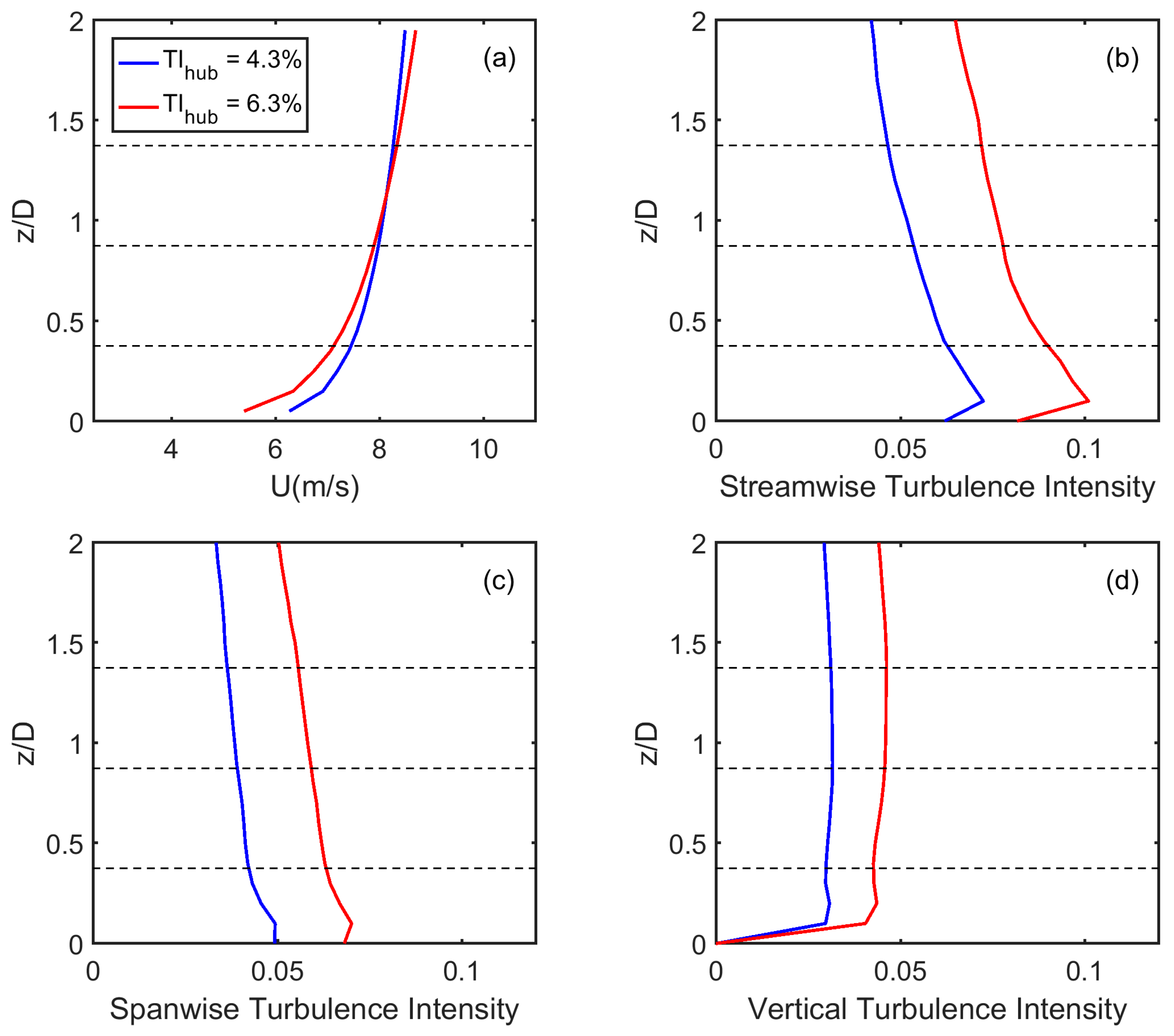
In this section, we present results from the large-eddy simulations of the two-turbine set up described in the previous section, operating in a neutrally-stratified atmospheric boundary layer flow over a flat terrain. As mentioned earlier, we considered two instances of turbulence intensity of 4.3% and 6.3% at the turbine hub height for the incoming wind, which from here on shall be referred to as Case 1 and Case 2 respectively. For this, two boundary layers that had the same time-averaged streamwise velocities at the turbine hub height, but different levels of turbulence, were generated using precursor simulations without turbines. The turbulence intensity of the boundary layer was altered by varying the value of surface roughness, which in Cases 1 and 2 were set at 5 × 10
−5 m and 5 × 10
−3 m respectively. The velocity of the incoming wind was then adjusted, by modifying the pressure gradient, to have a value of 8 m/s at turbine hub height in both cases. This was to ensure the same operating point for the upstream turbine in the baseline configuration for both cases, while ensuring different rates of wake recovery determined by the ambient turbulence level [
32].
Figure 2 shows the mean and turbulent characteristics of the incoming flow in both cases. The two boundary layers shown were then used as inflow for the simulations involving the turbines.
3.1. Effect of Pitching on the Wake Characteristics of a Turbine
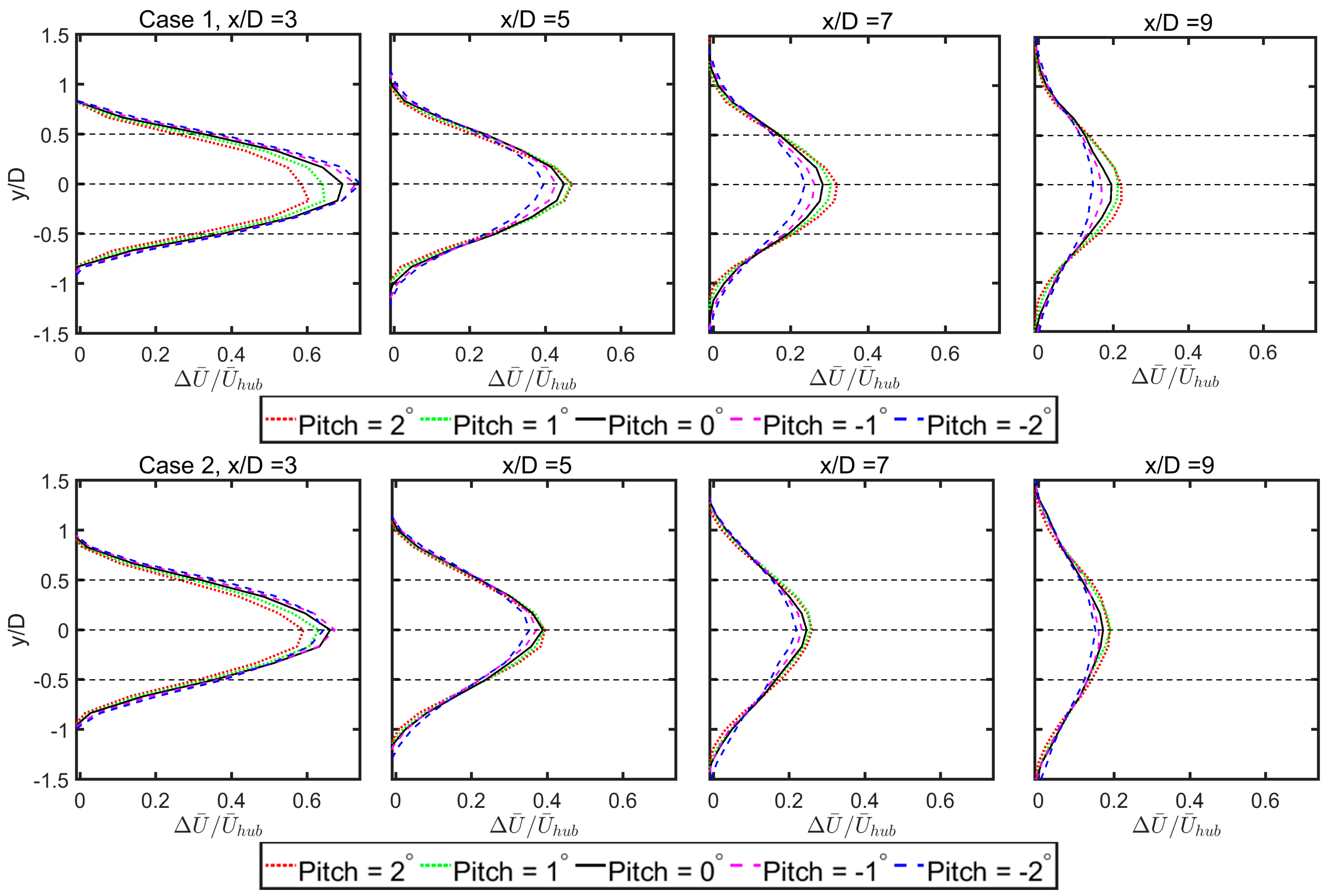
Of particular interest was the effect of pitching the blades of the front turbine on its wake characteristics downstream, since this determined the power generated by a second turbine located in the wake of the first. The wake is quantified with the normalized velocity deficit defined as
, where
stands for
, and
is time averaged streamwise velocity.
Figure 3 shows the profile of normalized velocity deficit at several locations downstream of the front turbine for the different instances of blade pitch angle. The pitching maneuver led to downregulation of the turbine from its optimum operating point, or in other words, a drop in its power generation, resulting in a modified wake profile relative to the baseline configuration.
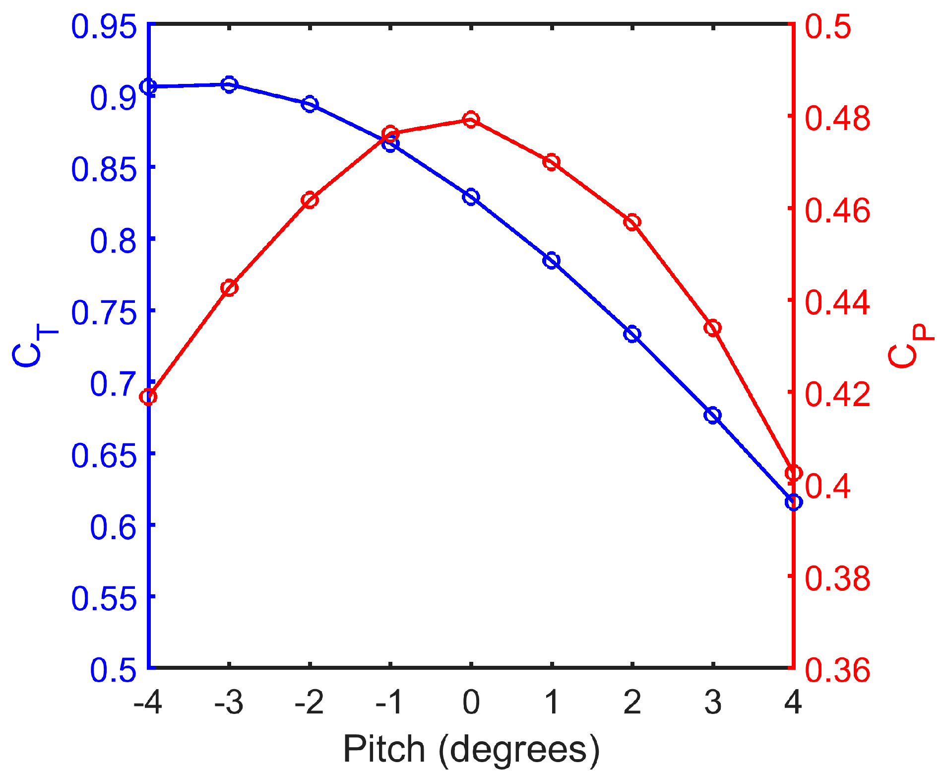
Figure 3 confirms this fact, but a closer examination of the profiles yields deeper insights into the wake recovery phenomena. To begin with, the velocity deficit was stronger in the near wake region for the negative direction of blade pitch offset (i.e., pitch to stall) compared to the positive direction (i.e., pitch to feather). This could be explained by the increase in the thrust coefficient of the turbine with the increase in blade pitch angle towards the negative side, and vice versa, as shown in
Figure 4.
An increase in thrust force on the turbine implied an increase in the loss of momentum from the incoming wind without useful power production, resulting in the higher velocity deficits in the near wake region, as can be seen in
Figure 3. Interestingly, however, a reversal of this relative difference in velocity deficit magnitude between a positively and negatively pitched turbine occurred, as the wake proceeded further downstream (i.e., from x/D = 5). At x/D = 5, the velocity deficit was lower for negative pitch offsets, implying an enhanced wake recovery for this direction of pitching compared to the other. Although pitching the turbine in either direction led to a drop in its power coefficient (as can be seen in
Figure 4), these facts indicated the existence of a “favorable” direction of pitching the front turbine blade for increasing power generation from a second turbine located in the wake. It was also seen that the difference in rate of wake recovery between the different instances of blade pitch offsets was most significant between x/D = 3 and x/D = 5, beyond which the relative difference in velocity deficits changed only marginally with downstream distance.
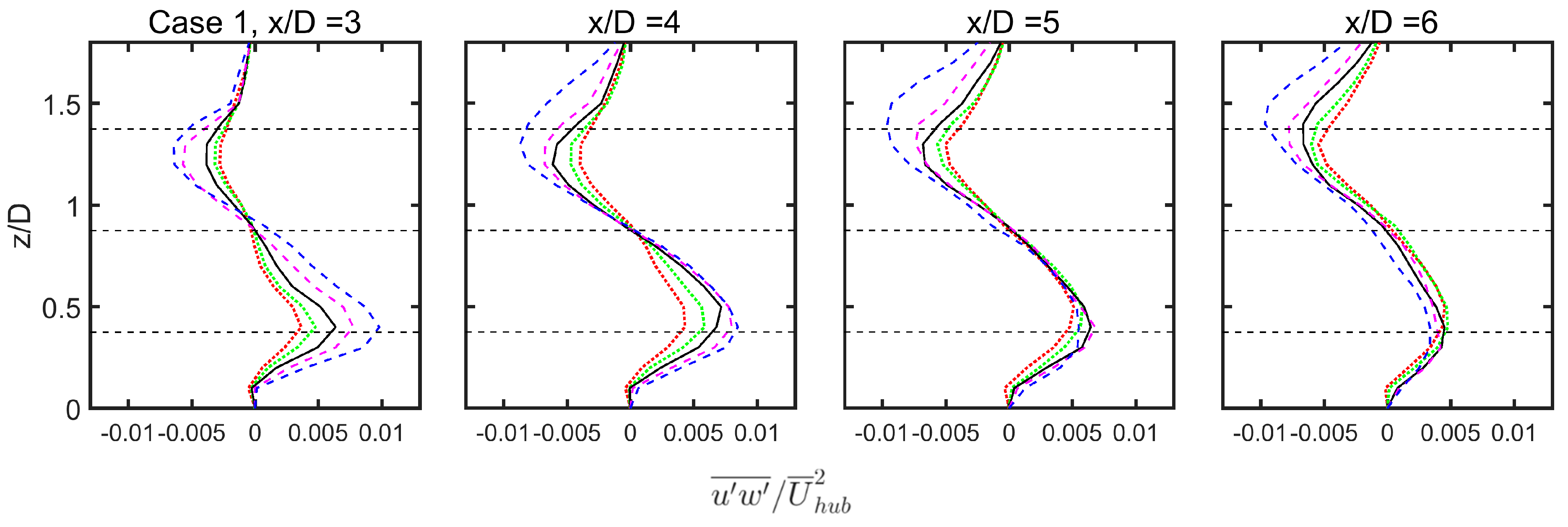
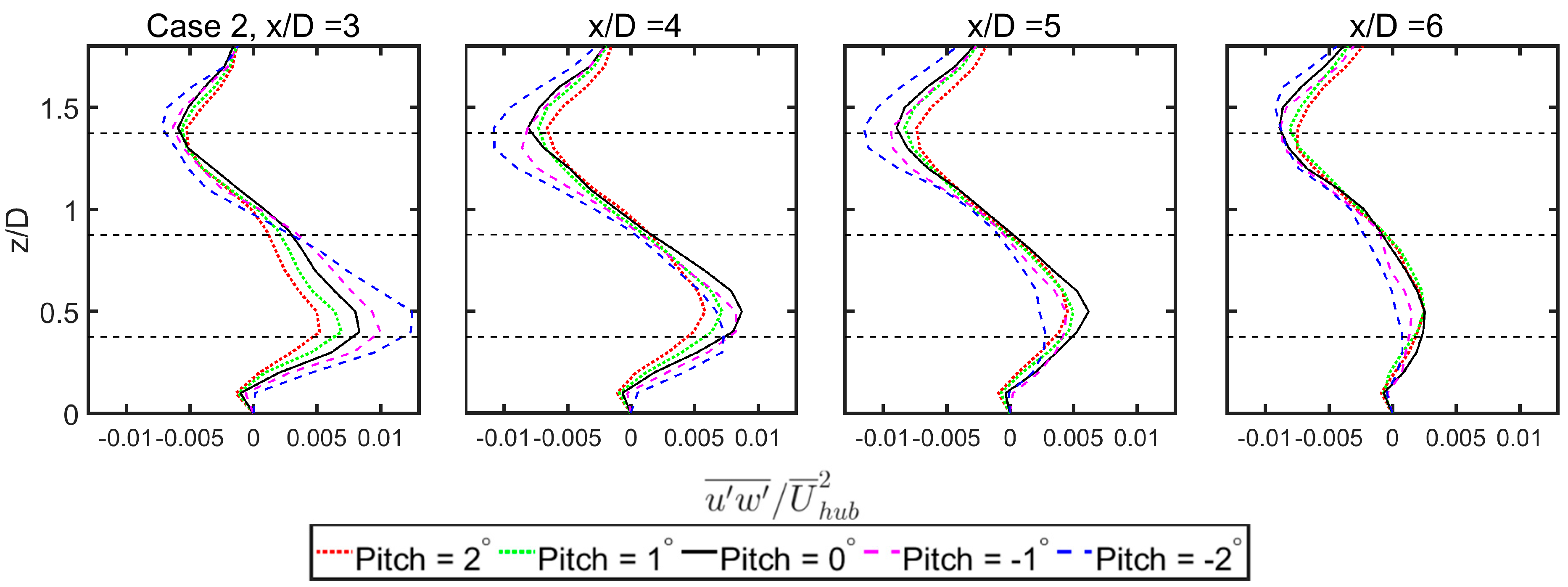
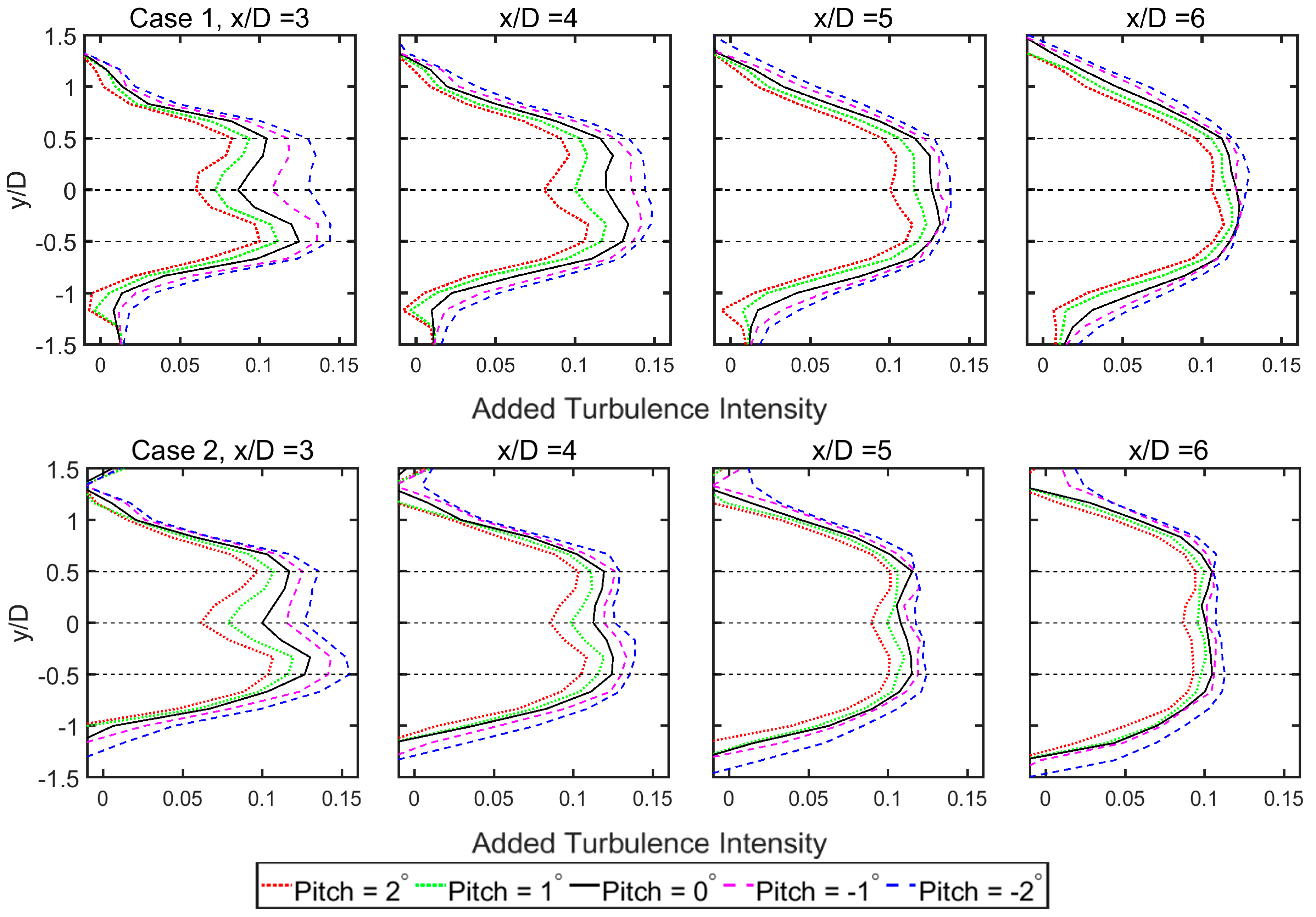
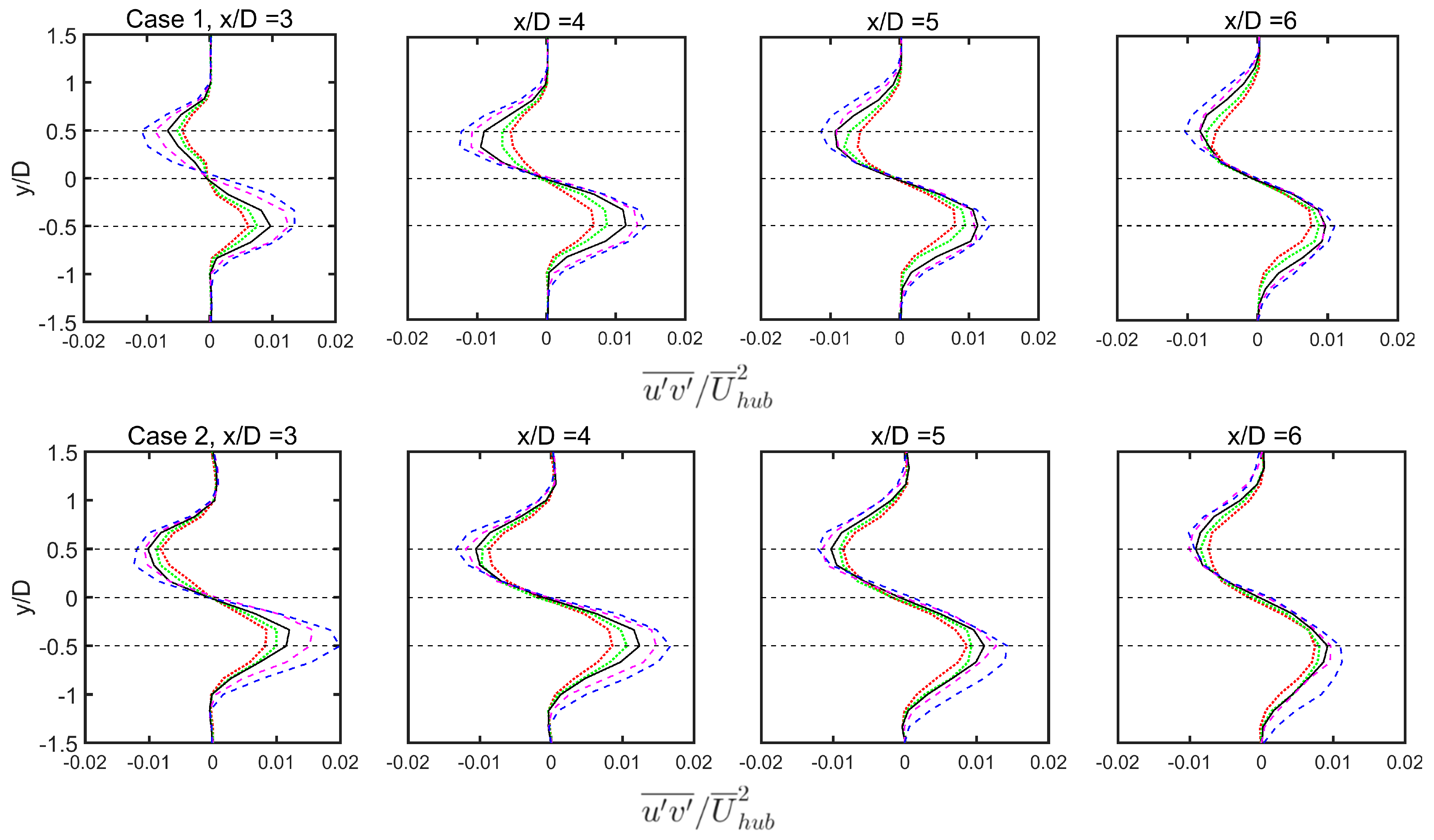
The difference in wake recovery with the variation in blade pitch angle of the turbine can be explained from
Figure 5,
Figure 6 and
Figure 7, which show the turbine-induced turbulence intensity, the normalized vertical turbulent flux, and the normalized lateral turbulent flux respectively, at several locations downstream for different pitch offsets of the turbine. The turbine-induced turbulence intensity can be defined as:
Here,
Iu is the total turbulence intensity,
Iu,inflow is the turbulence intensity from the inflow and
Iu,add is the added turbulence by the turbine. The normalized vertical turbulent flux, defined as
, and normalized lateral turbulent flux, defined as
, indicate the momentum flux from the surrounding boundary layer into the wake center, which aids its recovery as it proceeds downstream. It can be seen from the
Figure 5,
Figure 6 and
Figure 7 that both the momentum flux as well as the turbine-added turbulence were higher in case of negative pitch offsets, which explained the relatively faster initial recovery of wakes in such cases. As seen from
Figure 4, negative pitch offsets resulted in an increased thrust coefficient for the turbine, which in turn implied an increased shear on the edge of the turbine wake. This explained the higher turbine-induced turbulence, as well as the momentum flux, (whose magnitude indicated the turbulent shear stress on the flow) for negative pitch offsets. However, the relative difference in added turbulence intensity and momentum flux between the different pitch offsets decreased with downstream distance, with the difference most pronounced at x/D = 4. This implied that the most significant difference in wake recovery between the different blade offset cases happened between x/D = 3 and x/D = 5, a fact that can be confirmed from
Figure 3.
It should be noted, however, that the predominant factor affecting wake recovery was the ambient turbulence intensity, and a higher turbulence level in the incoming wind overshadowed the effects due to turbine-induced turbulence, as seen in Case 2. The wake recovery in this case followed the same trend as Case 1, with pitching to stall (negative pitch offsets) resulting in a faster recovery. However, the relative difference in velocity deficits between different pitch offsets were lesser in Case 2 in comparison to Case 1, where the ambient turbulence intensity was lower. This can be observed from
Figure 5,
Figure 6 and
Figure 7, where the relative difference between momentum flux and turbine-added turbulence between the different cases of pitch offsets was lesser in Case 2 compared to Case 1. This caused the increase in power generation of the downstream turbine due to downregulation of the upstream turbine to be less pronounced in Case 2 than in Case 1. A more detailed analysis of the power production from the two-turbine combination is given in the next section.
An additional point to note is that the increase in turbine-induced turbulence intensity was brought about through the pitching maneuver in this study, which increased the thrust coefficient of the turbine. However, these observations also reveal a possibility for the development of novel techniques at the level of turbine blade design, with the intention of enhancing wake recovery. This could allow for the design of new blade geometries that generate more turbulence, and consequently faster recovering wakes, without severe loss in power production.
3.2. A Two-Turbine Case—Power Production
Efficient power generation in wind farms necessitates adequate inter-turbine spacing to minimize the power losses from turbines that operate in the wake of the other turbines. The optimal spacing between individual turbines in wind farms depends on the rate of wake recovery, which in turn is affected by the ambient turbulence level. A range of turbine spacing between 3 D and 9 D can be found in wind farms, with the turbines placed closer to each other in onshore farms characterized by higher atmospheric turbulence, and farther apart in offshore wind farms where ambient turbulence is relatively lower. Hence, in this study we chose two inter-turbine spacings of 5 D and 7 D, since they both fell within this range (3 < x/D < 9), and also because we expected the pitch downregulation strategy to have the most pronounced effect at these distances based on the wake profiles of a single turbine shown in
Figure 3. The effect of downregulating the front turbine on the combined power output of the configuration was investigated for both cases of turbulence intensities.
From the wake profiles shown in the previous section, it is clear that only a negative pitch offset for the upwind turbine (pitch to stall) is beneficial for reducing power losses in the downstream one. Hence, only the results for this favorable direction of pitching are presented in this section.
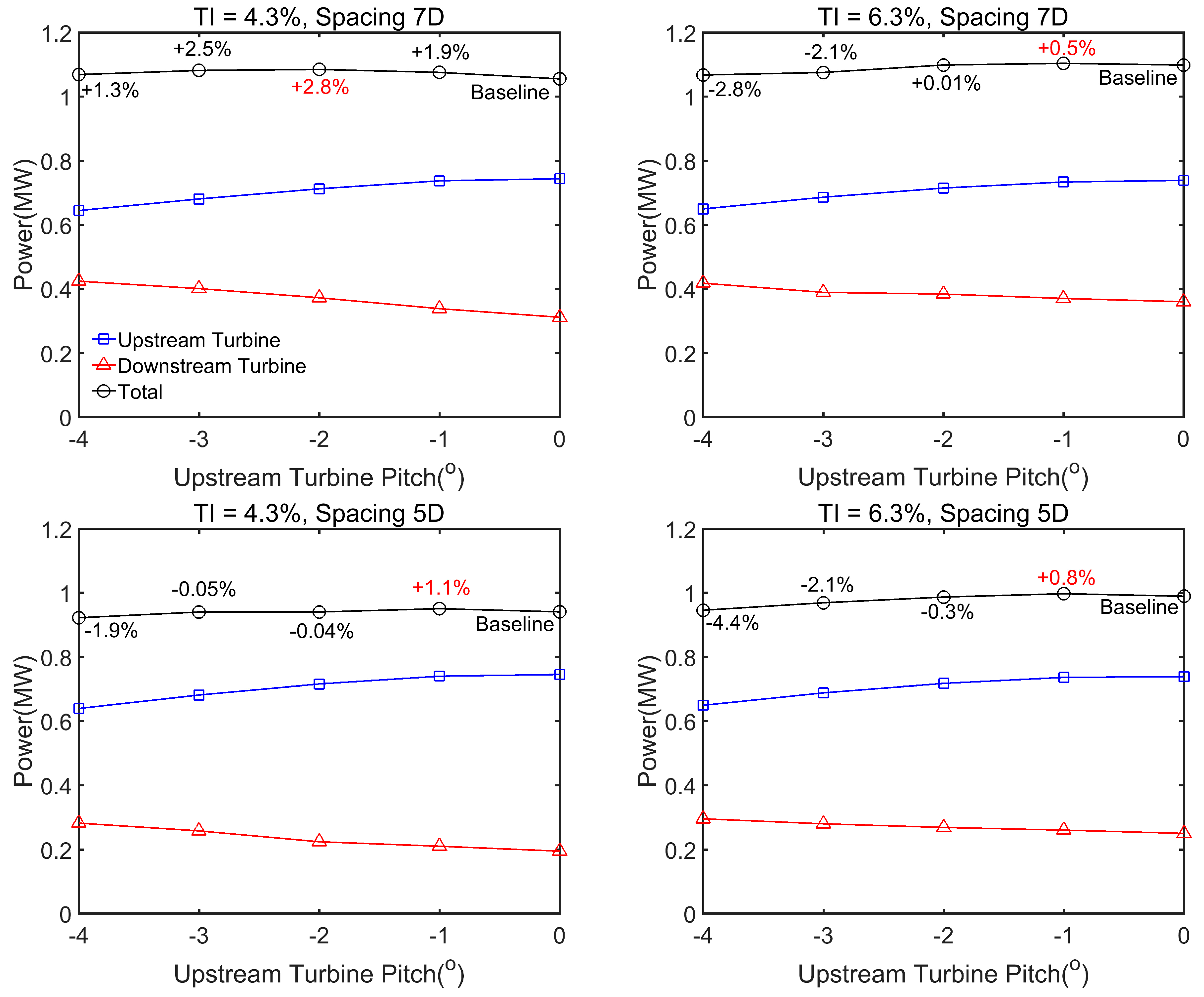
Figure 8 shows the variation of the combined power output of the two-turbine configuration with the pitch angle of the front turbine.
The results for two spacings of turbines (5 D and 7 D), for both cases of turbulence intensities are shown in
Figure 8. It can be seen that a gradual increase in pitch offset of Turbine 1 was accompanied by a gradual drop in its power, and an increase in power for the Turbine 2 located in the wake. Consistent with observations from the wake profiles, the increase in combined power production of the two-turbine configuration was higher for the case with lower turbulence intensity. The improvement was more pronounced when the turbine spacing was 7 D, which showed a peak increase of about 2.8%, whereas at 5 D, the peak was observed at 1.1%. This was expected, since from the wake profiles in
Figure 3, the difference in velocity deficits of a turbine with pitch offset with respect to the baseline was more pronounced at 7 D than at 5 D downstream. However, in case of the higher turbulence intensity of 6.3%, pitching generally resulted in a lower combined power output compared to no pitching maneuver being performed, for both turbine spacings of 7 D and 5 D. In this case, Turbine 2 was unable to compensate for the drop in power of Turbine 1, since the higher atmospheric turbulence offset its effects on the wake due to the pitch offsets of Turbine 1, causing negligible difference in wind velocity encountered by Turbine 2.
Of the four cases shown above for the combined power of the two-turbine configuration, the case with TI = 4.3% (Case 1) and an inter-turbine spacing of 7 D appeared to be a feasible scenario for the application of pitch downregulation strategy, since we saw a positive improvement of greater than 2% in the combined power generation of the configuration. It should be noted that these results were taken after the simulations were run for a duration of approximately 30 min of physical time, which was sufficiently long enough to sample all scales of turbulence in the flow. We had checked the results after averaging for longer durations, and had found that averaging over time windows greater than 20 min showed minor changes in results, with the peak improvement in power changing by less than 0.2%. These facts confirmed that the observed results were significant and not merely statistical variations due to flow unsteadiness.
The above results add to the existing knowledge on the viability of pitch regulation for optimizing wind farm power output. Previous studies in this direction had yielded seemingly contradictory results, with the wind tunnel measurements of Adaramola and Krogstad [
14] of a similar configuration to the two-turbines arrangement indicating a potential improvement of about 3% in wind farm efficiency via pitch regulation, while the LES results of others such as Annoni et al. [
30] and Gebraad et al [
31] suggesting negligible benefits from such a strategy. The work of Nilson et al. [
29] on the LES of Lillgrund wind farm also found no improvement in wind farm power output via pitch downregulation of the front row turbines. It should be noted here that the turbulence intensity of the incoming flow in the LES reported by Annoni et al. [
30] and Gebraad et al [
31] was 6%, while in the case of Nilson et al. [
29] it was 5.7%, all of which were similar to Case 2 of this study, where negligible improvement in power generation via pitch regulation was found. In this regard, we see an agreement with the results of the present work with the previous studies. However, the considerable improvement in combined power output observed in Case 1 indicates the strong influence of atmospheric turbulence on the feasibilty of this strategy. Since the work of Adaramola and Krogstad [
14] does not specify the turbulence intensity of the incoming flow, it can be suggested that their experimental conditions were closer to Case 1 of this study, which led to the considerable improvement in the power output of the two-turbine configuaration through the use of the pitch downregulation strategy.
It can be inferred from the observations from Cases 1 and 2 that the pitching of the upstream turbine is not beneficial for improving the combined power output of the configuration for most regimes of turbulence found in wind farms. However, such an inference still supports the selective application of pitch control strategies for improved efficiency, in cases of very low atmospheric turbulences that are still within the lower limits of turbulence intensities found in realistic situations. One example of such a scenario is reported by Abkar et al. [
33] in their study of the wake flow in a wind farm during a diurnal cycle. In their work, they simulated atmospheric boundary layer flow over a period of two full days, during which the turbulence characteristics of the boundary layer were reported. Their data for the temporal variation of the turbulence level in the boundary layer over the two-day period showed the turbulence intensity of the incoming wind at the hub height dropping to as low as 3% during the time spanning from 20:00 on the second day to 06:00 the following day, a period which was characterized by a stable boundary layer. The results for the second day are considered in our study to avoid any effects of initial conditions on the data for first day. With the surface roughness used for their studies being 0.05 m, the conditions reported were representative of the diurnal cycle of the boundary layer over relatively smooth surfaces. This, coupled with the fact that an inter-turbine spacing of 7 D is usually found in wind parks, implies the applicability of the results of Case 1 presented in this study, over a selected period from the typical operational day of wind farms situated on regions with low surface roughness.
The pitch regulation strategy is thus found to have selected scenarios of feasibility, determined by conditions of ambient atmospheric turbulence level and wind turbine spacing. However, it should be remembered that this study only considered a simple configuration of two turbines arranged with one behind the other, and thus, did not include the full range of conditions found in actual wind farms where several turbines operate simultaneously, with constant changes in wind directions. Optimizing the efficiency of wind farms will need more complex strategies identifying optimum pitch settings for individual turbines. Nevertheless, this work provides evidence, for the first time, of the key role of ambient atmospheric turbulence levels on the viability of pitch regulation for simple turbine configurations, which has the potential to assist in the development of more sophisticated control strategies in large wind farms.
4. Conclusions
This work investigated the role of ambient turbulence on the feasibility of downregulating individual wind turbines from their maximum power point using blade pitch offset for increasing the overall power generation in a wind farm. This was done using large-eddy simulations with the tuning-free Lagrangian scale-dependent dynamic model for subgrid-scale turbulent fluxes, coupled with an actuator disk with rotation model for parameterizing the turbine induced forces. This framework was used to simulate an arrangement of two Vestas V80 turbines, with the second turbine fully in the wake of the first, and the wake mitigation strategy applied to the front turbine. The influence of ambient atmospheric turbulence on the feasibility of the pitching strategy was studied, with the turbulence values chosen to simulate realistic wind conditions that can be found in wind farms over relatively smooth terrain.
The simulations indicated an enhanced wake recovery for negative pitch offsets of the blade (pitch to stall) over positive offsets (pitch to feather). The negative pitch offsets resulted in an increased thrust coefficient of the turbine, which caused increased shear on the edge of the turbine wake. This led to higher turbine-induced turbulence as well as turbulent momentum flux for negative pitch offsets, resulting in faster wake recovery. It was also seen that for atmospheric flows with low turbulence intensity (<4.5%), the faster wake recovery from this method of pitch regulation resulted in a peak improvement in power of approximately 2.8% over the baseline, for the two-turbine combination. However, it was seen that the effects of increased turbulent momentum flux and wake recovery due to pitching became insignificant at a higher ambient turbulence intensity of about 6%. Consequently, the technique of pitch downregulation resulted in a decrease in power for the combination compared to the baseline. This suggests the selective application of the pitch regulation strategy to instances of low atmospheric turbulence. A previous study [
33] of the diurnal variation of atmospheric turbulence indicated the prevalence of a strongly stable boundary layer over wind farms installed on relatively smooth land surfaces during extended periods of the cycle, where very low turbulence intensities of less than 4% at the turbine hub level was observed.
This study indicated the conditional viability of wake mitigation through pitch regulation for a simple two-turbine configuration. Although this did not fully represent the actual conditions in a wind farm where several wind turbines functioned in tandem, the identification of potential scenarios where pitch regulation is applicable through this work, can help develop more complex optimization strategies for increasing wind farm productivity in the future.
It should be noted that this work has focused on non-yawed turbines under full-wake conditions, for which the wind is directly aligned with the wind, and hence for which the effects on power production are expected to be greatest. The study of pitching combined with yawing and/or partial wake conditions could be an interesting topic for further future research. Additionally, this study has only considered the impact of blade pitch regulation on the power efficiency of the turbines; however, the effects of this maneuver on the fatigue loads on the turbine have not been considered. An application of this strategy in realistic situations should weigh in the potential benefits that we have reported, against any potential increase or decrease of the fatigue loads on the turbine, which could also be the focus of a future study.


